EP1299285B1 - Modular wrapping apparatus - Google Patents
Modular wrapping apparatus Download PDFInfo
- Publication number
- EP1299285B1 EP1299285B1 EP01952516A EP01952516A EP1299285B1 EP 1299285 B1 EP1299285 B1 EP 1299285B1 EP 01952516 A EP01952516 A EP 01952516A EP 01952516 A EP01952516 A EP 01952516A EP 1299285 B1 EP1299285 B1 EP 1299285B1
- Authority
- EP
- European Patent Office
- Prior art keywords
- wrap
- twist
- drum
- flow
- special
- Prior art date
- Legal status (The legal status is an assumption and is not a legal conclusion. Google has not performed a legal analysis and makes no representation as to the accuracy of the status listed.)
- Expired - Lifetime
Links
Images


Classifications
-
- B—PERFORMING OPERATIONS; TRANSPORTING
- B65—CONVEYING; PACKING; STORING; HANDLING THIN OR FILAMENTARY MATERIAL
- B65B—MACHINES, APPARATUS OR DEVICES FOR, OR METHODS OF, PACKAGING ARTICLES OR MATERIALS; UNPACKING
- B65B25/00—Packaging other articles presenting special problems
- B65B25/005—Packaging other articles presenting special problems packaging of confectionery
-
- B—PERFORMING OPERATIONS; TRANSPORTING
- B65—CONVEYING; PACKING; STORING; HANDLING THIN OR FILAMENTARY MATERIAL
- B65B—MACHINES, APPARATUS OR DEVICES FOR, OR METHODS OF, PACKAGING ARTICLES OR MATERIALS; UNPACKING
- B65B51/00—Devices for, or methods of, sealing or securing package folds or closures; Devices for gathering or twisting wrappers, or necks of bags
-
- B—PERFORMING OPERATIONS; TRANSPORTING
- B65—CONVEYING; PACKING; STORING; HANDLING THIN OR FILAMENTARY MATERIAL
- B65B—MACHINES, APPARATUS OR DEVICES FOR, OR METHODS OF, PACKAGING ARTICLES OR MATERIALS; UNPACKING
- B65B9/00—Enclosing successive articles, or quantities of material, e.g. liquids or semiliquids, in flat, folded, or tubular webs of flexible sheet material; Subdividing filled flexible tubes to form packages
- B65B9/06—Enclosing successive articles, or quantities of material, in a longitudinally-folded web, or in a web folded into a tube about the articles or quantities of material placed upon it
- B65B9/067—Enclosing successive articles, or quantities of material, in a longitudinally-folded web, or in a web folded into a tube about the articles or quantities of material placed upon it the web advancing continuously
Definitions
- the present invention relates generally to apparatus and methods for wrapping articles, and relates more particularly to such apparatus and methods useful for wrapping articles such as candy bars or other food products in a manner incorporating a wrap such as a single or double twist-wrap, an envelope wrap, a bunch wrap or a modified envelope wrap.
- the invention is applicable to wrapping performed with either a heat sealing method or a cold-seal adhesive.
- the great majority of candy bars are packaged by being wrapped and sealed in a film of wrapping material, on which is printed the desired package artwork, logos, etc.
- Such wraps are generally formed in the following way.
- a continuous film of the wrapping material is printed with the artwork and the like (this is generally done by the vendor of the film, not by the food packager).
- the products are deposited in the film with proper registration, so that the individual products line up with the artwork on the film.
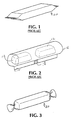
- the film is wrapped around the products 12 and sealed in a continuous seam 14 to form a tubular shape 16 (see Fig. 2). This tube 16 is then cut into parts at the correct locations to produce individual tubular lengths of film, each containing one product.
- wrap for food products involves wrapping individual pieces of the product in a film that is wrapped around the product, again in a tubular fashion, with a twist in each end (see 30, in Fig. 3). Small hard candies wrapped in this manner are also a familiar product.
- various other twist-wrap techniques are used for other products, such as lollipops.
- Other types of wrapping techniques useful for various food products are the envelope wrap, the bunch wrap and the modified envelope wrap. These wrapping techniques are well understood by those of ordinary skill in the art, and together with the double twist-wrap will be termed "special wraps" or "special wrapping techniques” herein.
- GB-A-910339 describes a twist wrapping machine comprising a rotary carrier head carrying a plurality of pairs of article grippers and, associated with each part of article grippers, two pairs of twister jaws mounted on the rotary carrier.
- EP-A-0733548 describes an apparatus for packaging confectionery products having various shapes.
- the apparatus includes a rotating transfer assembly and a rotating wrapping assembly.
- US-A-5490368 describes a confectionery wrapping machine including a transfer-and-rotate assembly, a rotating wrapping drum, and a rotating discharge assembly.
- GB-A-2220187 describes an apparatus for the transfer of sweets comprising a transfer wheel which is provided with pairs of sweet-grippers arranged to rotate the orientation of the sweet and to feed the sweet to a wrapper-feed station.
- GB-A-40913 describes the use of a Geneva gear ring to drive twist-wrapping jaws in a confectionery packaging machine.
- GB-A-2066202 describes a linear combination of a flow-wrap machine, a transfer chain that rotates partially wrapped articles, and a twist-wrapping device.
- a flow-wrap packaging line for wrapping a series of individual articles, comprising: a flow-wrap section, in which a film is formed into a tubular wrap about the articles; a cut-and-seal section, in which the tubular wrap is cut between each two successive articles, said cut-and-seal section being operable in a first mode, in which the tubular wrap is also sealed, thereby completing wrapping of the articles, and in a second mode, in which the tubular wrap is cut but not sealed; and characterized in that said packaging line further comprises a modular special-wrap section which is detachable from said cut-and-seal section of said flow-wrap machine, wherein said special-wrap section comprises: a receiving portion arranged such that, when said special-wrap section is attached to said cut-and-seal section, said receiving portion receives a tube-wrapped article into a predetermined location from said cut-and-seal section, and a special-w
- the detachable special-wrap section is a detachable twist-wrap section
- the special-wrap assembly is a twist-wrap assembly having rotatable grippers to grip ends of the tube-wrapped article, and to twist the ends to form a twist-wrapped article.
- the packaging line according to this aspect of the invention further comprises a control unit that generates control signals to control operation of the sections of the packaging line, the control signals including a registration signal and an encoder signal, and wherein the twist-wrap section has signal lines connectable to receive the registration signal and the encoder signal.
- the receiving portion comprises a transfer-and-rotate assembly that includes a drum rotatable about a first drum axis, at least one product gripper mounted on a peripheral surface of the drum, the product gripper being rotatable about a second axis perpendicular to the first drum axis, and a drive assembly that rotates that product gripper 90°, about the second axis while the drum rotates about the first drum axis.
- a transfer-and-rotate assembly that includes a drum rotatable about a first drum axis, at least one product gripper mounted on a peripheral surface of the drum, the product gripper being rotatable about a second axis perpendicular to the first drum axis, and a drive assembly that rotates that product gripper 90°, about the second axis while the drum rotates about the first drum axis.
- the twist-wrap assembly includes a twist-wrap drum and includes Geneva wheels that drive the twist grippers.
- the Geneva wheels cause the twist grippers to begin rotating immediately after the twist grippers have gripped the partially-wrapped article, and cause the twist grippers to continue to rotate through a predetermined angle, sufficient to effect a twist-wrap, and then to stop.
- the twist grippers close on the partially-wrapped article as the partially-wrapped article is received at the predetermined location, and open to release the twist-wrapped article as the twist-wrapped article is transferred from the twist-wrap assembly.
- the apparatus preferably further comprises a discharge drum that is located to receive the twist-wrapped article from the twist-wrap assembly as the twist-wrapped article is released by the twist-wrap assembly.
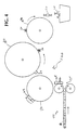
- Fig. 4 shows, schematically, the preferred embodiment of the present invention, a modular twist-wrap apparatus 100 together with a conventional continuous flow-wrap packaging line 50 (only a portion of which is shown).
- the conventional line being well known, will not be described or illustrated in any detail, and by itself, it does not form part of the present invention (although the combination of a modified conventional packaging line with the modular apparatus claimed herein, is within the scope of the invention as claimed).
- Fig. 1 illustrates the well-known form of candy bar wrapping 20 obtained with the conventional type of continuous flow-wrapping packaging process.
- the products 12 being wrapped are placed on a continuous film of known composition, which is usually preprinted with artwork, logos, product name, etc.
- the side edges of the film are brought together and welded or glued to produce a seam 14, thus forming a tubular shape 16 containing the articles 12 being packaged, as illustrated in Fig. 2.
- the tubular shape is then divided into portions each containing one product, and the ends of each portion are welded or glued shut, thus producing the form shown in Fig. 1.
- These conventional processing steps like the apparatus used to perform them, are well known in the art and will not be described in greater detail.
- the operation of the latter is modified in certain respects.
- Second, the cut-and-seal 55 (the component of the standard continuous flow-wrap line that cuts the tubular shape 16 shown in Fig. 2 into individual portions and then seals the ends), is set only to perform the cutting, and does not seal the ends of the individual packages.
- Third, the registration and the encoder signals used in the control of the standard line are supplied to the modular twist-wrap apparatus. According to the preferred embodiment, these are the only control signals that need to be supplied to the modular twist-wrap apparatus from the standard line.
- the modular twist-wrap apparatus 100 receives the tubular products, in their individual "product wraps" 24 (i.e., a segment cut from tube 16 and containing the product 22 to be packaged in a single package), from the upper arbor 57 of the cut-and-seal 55.
- Three drums 110, 130 and 150 are provided in the twist-wrap apparatus, and perform the following operations on the products.
- the first drum 110 is a transfer-and-rotate drum (see also Figs. 5 and 9), which receives the product 24 from the cut-and-seal 55 into a product gripper 112 (Fig. 5). While the product 24 is transported to the second drum 130 by rotation of the transfer-and-rotate drum 110, the product gripper 112 itself is rotated to reorient the product by 90° (see Figs. 8 and 9). As a result, the product 24 is delivered to the second drum 130 in an orientation with the open ends of the product's "wrap" extending in a line parallel to the axis of rotation of the second drum (this is indicated schematically in Fig. 4, where product 24 is viewed from the side while in the cut-and-seal, is rotating on the first drum 110, and is seen end-on while on drum 130).
- the second drum 130 is where the actual twist-wrap formation is performed.
- the product 24, held by a product gripper 112 (like those on the transfer-and-rotate drum 110), is gripped at each end by twist grippers 132 (see Fig. 6), which are timed to close on the "tube” once the product is securely received by the product gripper 112 on the twist-wrap drum 130.
- the twist grippers 132 are then rotated about their own axis (parallel to the axis of drum 130) through an angle of 720° while the twist-wrap drum 130 is itself rotating. The force applied in this fashion twists the ends of the "tube” into the desired twist-wrap shape, and the adhesive seals the package.
- the twist grippers 132 are then opened, and the product 30 ("30" rather than "24” because it is now twist-wrapped) is transferred to the third drum 150, the discharge drum.
- the discharge drum 150 has the function of receiving the packaged product 30 from the twist-wrap drum 130, delivering the product to the desired discharge point, and discharging it in an orderly fashion.
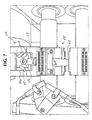
- the transfer-and-rotate drum 110 has twelve product grippers 112 provided on its circumference.
- the product gripper 112 comprises a base portion, or head, 114 whose upper surface contains vacuum tooling; that surface is shown as rectangular, but could be given any shape found advantageous in handling the particular product in question.
- One or more ports 116 are provided in the upper surface of the head 114 of the product gripper 112 to permit the application of suction from the interior of the drum, to hold the product and the wrap securely against the product gripper 112.
- the product gripper 112 has three linear rods or fingers 118, two along one side and one on the opposing side of the head 114.
- rods 118 are each movable between a closed position, in which they approach each other and thus grip and secure the product, in cooperation with the vacuum suction, and an open position, in which they are moved outward from each other and away from the product. Additional views of such product gripper 112' and 112" in place on one of the drums, are provided in Figs. 10 and 12. These versions of the product gripper 112' and 112" differ in a number of details, such as the shape of fingers or rods 118' and 118", from the design shown in Fig. 5.
- the lateral or circumferential surface of the transfer-and-rotate drum 110, on which the twelve product grippers 112 are mounted, is actually made up of twelve flat surfaces 120 of equal size, each carrying one of the product grippers 112.
- Each product gripper 112 is mounted such that it can be rotated on the flat surface 120 on which it is mounted, the rotation being about an axis passing through the product gripper 112 and through the axis of the transfer-and-rotate drum 110 itself.
- the product gripper 112 itself is caused to rotate so as to reorient the product 24 (see Figs. 8 - 10).
- the product gripper 112 is rotated through 90°, so that the open ends of the product "tube” 24 lie along a line parallel to the drum axis. This rotation of the product gripper is performed while the drum 110 has rotated through 240°. The product 24 is now in the proper place and orientation to be transferred to the twist-wrap drum 130.
- the transfer to the twist-wrap drum 130 is performed by the rods 118 of the product gripper 112 being moved to their open position, and then the vacuum suction being deactivated, to release the product 24 onto an identical product gripper 112 on the twist-wrap drum 130. At the same time, vacuum suction is applied to the product 24 by the product gripper 112 that is receiving the product onto the twist-wrap drum 130, and the rods 118 of the receiving product gripper 112 are closed to secure the product 24, completing the transfer.
- the opening and closing of the rods 118 on the product grippers 112 is controlled by a face cam arrangement, while the rotation of the product grippers 112 to reorient the product is achieved by means of a barrel cam arrangement. Since these techniques are well understood in the art, they need not be described in detail.
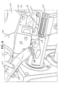
- the twist-wrap drum 130 actually includes a center drum 134 disposed between an inner drum 136 and an outer drum 138, all three of which are driven to rotate at the same speed.
- the center drum 134 has on its lateral or circumferential surface twelve product grippers 112, which are identical to those of the transfer-and-rotate drum 110 but which cannot rotate about their own axes. As a result, the product remains in the same orientation all the time it is on the twist-wrap drum 130.
- the inner and outer drums 136 and 138 each carry twelve twist grippers 132, one adjacent to each of the product grippers 112 on the center drum 134.
- Each twist gripper 132 has a pair of jaws 140, which can open and close, and are supported for rotation about the twist gripper's own axis (which is parallel to the axis of the twist-wrap drum 130).
- the housings 142 and 144 of the twist grippers 132 are not all the same, some containing one twist gripper 132, and some containing two each.
- posts 146 extend across the center drum 134 and connect these larger housings 144. The purpose of these double housings 144 and the posts 146 is to supply the drive force from the inner drum 136 to the outer drum 138, using techniques well-known in the art.
- the twist grippers 132 do not rotate at all times, but only the amount and at the times necessary to achieve the desired twist-wraps.
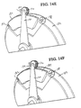
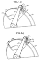
- they are driven by Geneva wheel mechanisms 180 shown in detail in Figs. 11 and 14A - 14J.
- One such mechanism is provided for each of the 24 twist grippers 132, and is located at one end of the associated twist gripper 132.
- the inner and outer drums 136 and 138 each have a respective disc 182 (see Fig. 14A) on which is mounted a radial gear rack 184, together with two pins, an acceleration pin 186 and a deceleration pin 188, which are respectively at the beginning and the end of the radial gear rack 184. These two discs 182 are stationary during rotation of the twist-wrap drum 130.
- Each Geneva wheel mechanism 180 is provided with a mounting 170 that carries the Geneva wheel mechanism 180 smoothly on the surface of the drum 136 or 138.
- a rotatable arm 190 for each of the twist grippers 132 is mounted coaxially with the disc 182 , at the radially-outer end of which is a small gear wheel 192, which in operation rides along and in engagement with the radial gear rack 184.
- a cam path 194 is secured to the gear wheel 192, and is caused to rotate as the gear wheel 192 moves along the radial gear rack 184.
- These cam paths each have portions that are to engage the acceleration and deceleration pins 186 and 188, respectively.
- each of the cam paths 194 in turn come into engagement with the acceleration pin 186, and the associated gear wheel 192 then engages and rides along the gear rack 184 to drive the twist gripper 132, rotating the latter through 720°, thus twisting the end of the product "wrap" and forming the twist-wrap.
- the formation of the twist-wrap is assisted by an arcuate plate 196 (shown in Figs. 11 and 13), which helps hold the product in place against the product gripper 112 as the twist grippers 132 twist.
- the twist grippers 132 adjacent to that product gripper 112 are moved to the closed position, gripping the ends of the product "wrap".
- the twist grippers 132 open, and the twist-wrapped product 30 is ready to be transferred to the discharge drum 150.
- the opening and closing of the twist grippers 132 is achieved by a barrel cam. The timing of this is controlled by the indexing of the Geneva wheel 180 itself, thus guaranteeing that the twist grippers 132 will engage and securely grip the product "wrap" before the twisting begins. Again, the further details of these cam arrangements are within the ordinary level of knowledge of those in the art, and need not be described further.
- the discharge drum 150 is provided with twelve product grippers 112 identical to those of the other two drums 110 and 130 (but, unlike those of the transfer-and-rotate drum 110, not themselves mounted for rotation).
- the transfer of the product 30 from the twist-wrap drum 130 to the discharge drum 150 is achieved in the same manner as that from the transfer-and-rotate drum 110 to the twist-wrap drum 130, and therefore will not be described in detail.
Abstract
Description
- The present invention relates generally to apparatus and methods for wrapping articles, and relates more particularly to such apparatus and methods useful for wrapping articles such as candy bars or other food products in a manner incorporating a wrap such as a single or double twist-wrap, an envelope wrap, a bunch wrap or a modified envelope wrap. The invention is applicable to wrapping performed with either a heat sealing method or a cold-seal adhesive.
- The great majority of candy bars are packaged by being wrapped and sealed in a film of wrapping material, on which is printed the desired package artwork, logos, etc. Such wraps are generally formed in the following way. A continuous film of the wrapping material is printed with the artwork and the like (this is generally done by the vendor of the film, not by the food packager). In the actual packaging process, the products are deposited in the film with proper registration, so that the individual products line up with the artwork on the film. The film is wrapped around the
products 12 and sealed in a continuous seam 14 to form a tubular shape 16 (see Fig. 2). Thistube 16 is then cut into parts at the correct locations to produce individual tubular lengths of film, each containing one product. Both ends of each of these are then sealed by heat sealing methods or cold-seal adhesive, completing the formation of the familiar wrapped product 20 (see Fig. 1). Commonly, the cutting and the sealing are performed simultaneously, by a mechanism known as a cut-and-seal. These techniques are referred to herein as the conventional "flow-wrap" process. - Another form of wrap for food products, such as candies, involves wrapping individual pieces of the product in a film that is wrapped around the product, again in a tubular fashion, with a twist in each end (see 30, in Fig. 3). Small hard candies wrapped in this manner are also a familiar product. (In contrast to this double twist-wrap, various other twist-wrap techniques are used for other products, such as lollipops. Other types of wrapping techniques useful for various food products are the envelope wrap, the bunch wrap and the modified envelope wrap. These wrapping techniques are well understood by those of ordinary skill in the art, and together with the double twist-wrap will be termed "special wraps" or "special wrapping techniques" herein.)
- GB-A-910339 describes a twist wrapping machine comprising a rotary carrier head carrying a plurality of pairs of article grippers and, associated with each part of article grippers, two pairs of twister jaws mounted on the rotary carrier.
- EP-A-0733548 describes an apparatus for packaging confectionery products having various shapes. The apparatus includes a rotating transfer assembly and a rotating wrapping assembly.
- US-A-5490368 describes a confectionery wrapping machine including a transfer-and-rotate assembly, a rotating wrapping drum, and a rotating discharge assembly.
- GB-A-2220187 describes an apparatus for the transfer of sweets comprising a transfer wheel which is provided with pairs of sweet-grippers arranged to rotate the orientation of the sweet and to feed the sweet to a wrapper-feed station.
- GB-A-40913 describes the use of a Geneva gear ring to drive twist-wrapping jaws in a confectionery packaging machine.
- GB-A-2066202 describes a linear combination of a flow-wrap machine, a transfer chain that rotates partially wrapped articles, and a twist-wrapping device.
- It would be desirable to provide an apparatus and a method capable of wrapping products, such as candy bars, with a double twist-wrap. It would be especially desirable to provide a modular apparatus that could be used with a standard continuous flow-wrap line of the type used for wrapping candy bars, so that the continuous flow-wrap line could be used as desired either to turn out double twist-wrapped
product 30, or product wrapped in thefamiliar packaging 20 with both ends of the wrap sealed in a flat shape. - In addition, it would be desirable to provide a modular apparatus that could be used with a standard continuous flow-wrap line of the type used for wrapping candy bars with one or another of the special wrapping techniques mentioned above, including bunch wrap, single twist wrap, envelope wrap, and modified envelope wrap, such that the continuous flow-wrap line could be used as desired either to turn out product wrapped using such special wrap, or product wrapped in the familiar packaging with both ends of the wrap sealed in a flat shape.
- Accordingly, it is one object of the invention to provide an apparatus that can be attached to a flow-wrap line for twist-wrapping (or other special wrapping), and can be deactivated when the line is to be used for standard continuous-flow wrapping.
- According to the present invention, these objects are achieved by providing a flow-wrap packaging line for wrapping a series of individual articles, comprising: a flow-wrap section, in which a film is formed into a tubular wrap about the articles; a cut-and-seal section, in which the tubular wrap is cut between each two successive articles, said cut-and-seal section being operable in a first mode, in which the tubular wrap is also sealed, thereby completing wrapping of the articles, and in a second mode, in which the tubular wrap is cut but not sealed; and characterized in that said packaging line further comprises a modular special-wrap section which is detachable from said cut-and-seal section of said flow-wrap machine, wherein said special-wrap section comprises: a receiving portion arranged such that, when said special-wrap section is attached to said cut-and-seal section, said receiving portion receives a tube-wrapped article into a predetermined location from said cut-and-seal section, and a special-wrap assembly having at least one set of elements adapted to form a special wrap in the tube-wrapped article.
- Preferably, the detachable special-wrap section is a detachable twist-wrap section, and the special-wrap assembly is a twist-wrap assembly having rotatable grippers to grip ends of the tube-wrapped article, and to twist the ends to form a twist-wrapped article.
- Preferably, the packaging line according to this aspect of the invention further comprises a control unit that generates control signals to control operation of the sections of the packaging line, the control signals including a registration signal and an encoder signal, and wherein the twist-wrap section has signal lines connectable to receive the registration signal and the encoder signal.
- Preferably, the receiving portion comprises a transfer-and-rotate assembly that includes a drum rotatable about a first drum axis, at least one product gripper mounted on a peripheral surface of the drum, the product gripper being rotatable about a second axis perpendicular to the first drum axis, and a drive assembly that rotates that product gripper 90°, about the second axis while the drum rotates about the first drum axis.
- Preferably, the twist-wrap assembly includes a twist-wrap drum and includes Geneva wheels that drive the twist grippers. Preferably, the Geneva wheels cause the twist grippers to begin rotating immediately after the twist grippers have gripped the partially-wrapped article, and cause the twist grippers to continue to rotate through a predetermined angle, sufficient to effect a twist-wrap, and then to stop.
- Preferably, the twist grippers close on the partially-wrapped article as the partially-wrapped article is received at the predetermined location, and open to release the twist-wrapped article as the twist-wrapped article is transferred from the twist-wrap assembly. In these embodiments, the apparatus preferably further comprises a discharge drum that is located to receive the twist-wrapped article from the twist-wrap assembly as the twist-wrapped article is released by the twist-wrap assembly.
- Other features and advantages of the present invention will be more fully understood from a consideration of the following detailed description of the preferred embodiments, taken in conjunction with the accompanying drawings.
-
- Fig 1. is a view of a product wrapped by a conventional continuous-flow-wrap packaging line like that shown in part in Fig. 4.
- Fig. 2 shows two articles of a product in a sheet of film wrap that has been folded around the product, and seamed, to form a tubular shape containing the product, prior to the cutting and sealing of the individual packages in conventional flow-wrap processing.
- Fig. 3 shows a product wrapped using the twist-wrap apparatus of the present invention.
- Fig. 4 is a schematic view illustrating a twist-wrap apparatus according to the preferred embodiment of the invention, attached to a conventional continuous-flow-wrap packaging line.
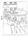
- Fig. 5 is a front view of the modular twist-wrap apparatus according to the preferred embodiment.
- Fig. 6 illustrates a detail of the second drum of the embodiment shown in Fig. 5, and shows several sets of the twist grippers used to effect a double twist-wrap.
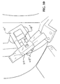
- Figs. 7 - 10 and 13 illustrate steps in the use of the preferred embodiment to produce a double twist-wrapped product like that shown in Fig. 3. More specifically, Fig. 7 illustrates the transfer of an article to the preferred embodiment from the cut-and-seal device, Figs. 8 - 10 show the rotation of the articles on the first drum, and Fig. 13 shows the transfer of the twist-wrapped article from the second drum to the third drum of the preferred embodiment.
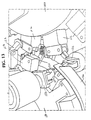
- Fig. 11 shows additional details of the construction of the second drum of the preferred embodiment, and in particular shows the Geneva wheels used in that embodiment.
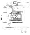
- Fig. 12 shows one version of a product gripper, as used on all three drums of the preferred embodiment.
- Figs. 14A - 14J are a sequence of views illustrating the operation of the Geneva wheels used in the preferred embodiment.
-
- Fig. 4 shows, schematically, the preferred embodiment of the present invention, a modular twist-
wrap apparatus 100 together with a conventional continuous flow-wrap packaging line 50 (only a portion of which is shown). The conventional line, being well known, will not be described or illustrated in any detail, and by itself, it does not form part of the present invention (although the combination of a modified conventional packaging line with the modular apparatus claimed herein, is within the scope of the invention as claimed). - Fig. 1 illustrates the well-known form of candy bar wrapping 20 obtained with the conventional type of continuous flow-wrapping packaging process. In the conventional process, the
products 12 being wrapped are placed on a continuous film of known composition, which is usually preprinted with artwork, logos, product name, etc. The side edges of the film are brought together and welded or glued to produce a seam 14, thus forming atubular shape 16 containing thearticles 12 being packaged, as illustrated in Fig. 2. In the conventional processing, the tubular shape is then divided into portions each containing one product, and the ends of each portion are welded or glued shut, thus producing the form shown in Fig. 1. These conventional processing steps, like the apparatus used to perform them, are well known in the art and will not be described in greater detail. - When the modular twist-
wrap apparatus 100 of the preferred embodiment is attached to and used with the standard continuous flow-wrap line 50, the operation of the latter is modified in certain respects. First, since it is desired to form a twist-wrap rather than a flat seam at each end of the package, the placement of adhesive on the film must be adjusted accordingly (the twists that are formed at the ends of the package may be secured in any fashion that proves effective, including the use of either heat-seal or a cold adhesive). Second, the cut-and-seal 55 (the component of the standard continuous flow-wrap line that cuts thetubular shape 16 shown in Fig. 2 into individual portions and then seals the ends), is set only to perform the cutting, and does not seal the ends of the individual packages. Third, the registration and the encoder signals used in the control of the standard line are supplied to the modular twist-wrap apparatus. According to the preferred embodiment, these are the only control signals that need to be supplied to the modular twist-wrap apparatus from the standard line. - The modular twist-
wrap apparatus 100 receives the tubular products, in their individual "product wraps" 24 (i.e., a segment cut fromtube 16 and containing theproduct 22 to be packaged in a single package), from the upper arbor 57 of the cut-and-seal 55. Threedrums - The
first drum 110 is a transfer-and-rotate drum (see also Figs. 5 and 9), which receives theproduct 24 from the cut-and-seal 55 into a product gripper 112 (Fig. 5). While theproduct 24 is transported to thesecond drum 130 by rotation of the transfer-and-rotatedrum 110, theproduct gripper 112 itself is rotated to reorient the product by 90° (see Figs. 8 and 9). As a result, theproduct 24 is delivered to thesecond drum 130 in an orientation with the open ends of the product's "wrap" extending in a line parallel to the axis of rotation of the second drum (this is indicated schematically in Fig. 4, whereproduct 24 is viewed from the side while in the cut-and-seal, is rotating on thefirst drum 110, and is seen end-on while on drum 130). - The
second drum 130 is where the actual twist-wrap formation is performed. For this purpose, theproduct 24, held by a product gripper 112 (like those on the transfer-and-rotate drum 110), is gripped at each end by twist grippers 132 (see Fig. 6), which are timed to close on the "tube" once the product is securely received by theproduct gripper 112 on the twist-wrap drum 130. The twist grippers 132 are then rotated about their own axis (parallel to the axis of drum 130) through an angle of 720° while the twist-wrap drum 130 is itself rotating. The force applied in this fashion twists the ends of the "tube" into the desired twist-wrap shape, and the adhesive seals the package. The twist grippers 132 are then opened, and the product 30 ("30" rather than "24" because it is now twist-wrapped) is transferred to thethird drum 150, the discharge drum. - The
discharge drum 150 has the function of receiving the packagedproduct 30 from the twist-wrap drum 130, delivering the product to the desired discharge point, and discharging it in an orderly fashion. - As shown in Fig. 5, the transfer-and-rotate
drum 110 has twelveproduct grippers 112 provided on its circumference. Theproduct gripper 112 comprises a base portion, or head, 114 whose upper surface contains vacuum tooling; that surface is shown as rectangular, but could be given any shape found advantageous in handling the particular product in question. One or more ports 116 (only one is shown) are provided in the upper surface of thehead 114 of theproduct gripper 112 to permit the application of suction from the interior of the drum, to hold the product and the wrap securely against theproduct gripper 112. In the preferred embodiment, theproduct gripper 112 has three linear rods orfingers 118, two along one side and one on the opposing side of thehead 114. Theserods 118 are each movable between a closed position, in which they approach each other and thus grip and secure the product, in cooperation with the vacuum suction, and an open position, in which they are moved outward from each other and away from the product. Additional views ofsuch product gripper 112' and 112" in place on one of the drums, are provided in Figs. 10 and 12. These versions of theproduct gripper 112' and 112" differ in a number of details, such as the shape of fingers orrods 118' and 118", from the design shown in Fig. 5. - The lateral or circumferential surface of the transfer-and-rotate
drum 110, on which the twelveproduct grippers 112 are mounted, is actually made up of twelveflat surfaces 120 of equal size, each carrying one of theproduct grippers 112. Eachproduct gripper 112 is mounted such that it can be rotated on theflat surface 120 on which it is mounted, the rotation being about an axis passing through theproduct gripper 112 and through the axis of the transfer-and-rotatedrum 110 itself. - As an
empty product gripper 112 on the transfer-and-rotatedrum 110 passes theupper arbor 55 of the cut-and-seal 50 (see Figs. 7 and 8), the vacuum suction is actuated in thatproduct gripper 112, while that holding theproduct 24 on the cut-and-sealupper arbor 55 is deactivated. This releases theproduct 24 from the cut-and-seal 50, and transfers it to theproduct gripper 112 on the transfer-and-rotatedrum 110. Therods 118 on theproduct gripper 112 move to their closed position, holding and orienting theproduct 24 on theproduct gripper 112. As thedrum 110 rotates about its axis to advance theproduct 24 toward the twist-wrap drum 130, theproduct gripper 112 itself is caused to rotate so as to reorient the product 24 (see Figs. 8 - 10). In the preferred embodiment, theproduct gripper 112 is rotated through 90°, so that the open ends of the product "tube" 24 lie along a line parallel to the drum axis. This rotation of the product gripper is performed while thedrum 110 has rotated through 240°. Theproduct 24 is now in the proper place and orientation to be transferred to the twist-wrap drum 130. - The transfer to the twist-
wrap drum 130 is performed by therods 118 of theproduct gripper 112 being moved to their open position, and then the vacuum suction being deactivated, to release theproduct 24 onto anidentical product gripper 112 on the twist-wrap drum 130. At the same time, vacuum suction is applied to theproduct 24 by theproduct gripper 112 that is receiving the product onto the twist-wrap drum 130, and therods 118 of the receivingproduct gripper 112 are closed to secure theproduct 24, completing the transfer. (The remainder of the description of the operation of the twist-wrap drum 130 will be provided in the following section.) As the transfer-and-rotatedrum 110 continues to rotate through the next 120°, theproduct gripper 112, now empty, is rotated back into its original orientation, so that it is ready to receive a product upon reaching the cut-and-seal 50 again. - The opening and closing of the
rods 118 on theproduct grippers 112 is controlled by a face cam arrangement, while the rotation of theproduct grippers 112 to reorient the product is achieved by means of a barrel cam arrangement. Since these techniques are well understood in the art, they need not be described in detail. - The twist-
wrap drum 130, as is seen most clearly in Fig. 6, actually includes acenter drum 134 disposed between an inner drum 136 and anouter drum 138, all three of which are driven to rotate at the same speed. The center drum 134has on its lateral or circumferential surface twelveproduct grippers 112, which are identical to those of the transfer-and-rotatedrum 110 but which cannot rotate about their own axes. As a result, the product remains in the same orientation all the time it is on the twist-wrap drum 130. - The inner and
outer drums 136 and 138 each carry twelvetwist grippers 132, one adjacent to each of theproduct grippers 112 on thecenter drum 134. Eachtwist gripper 132 has a pair ofjaws 140, which can open and close, and are supported for rotation about the twist gripper's own axis (which is parallel to the axis of the twist-wrap drum 130). It will be noted that thehousings twist grippers 132 are not all the same, some containing onetwist gripper 132, and some containing two each. Moreover, posts 146 extend across thecenter drum 134 and connect theselarger housings 144. The purpose of thesedouble housings 144 and theposts 146 is to supply the drive force from the inner drum 136 to theouter drum 138, using techniques well-known in the art. - In the preferred embodiment, the
twist grippers 132 do not rotate at all times, but only the amount and at the times necessary to achieve the desired twist-wraps. For this purpose, they are driven byGeneva wheel mechanisms 180 shown in detail in Figs. 11 and 14A - 14J. One such mechanism is provided for each of the 24twist grippers 132, and is located at one end of the associatedtwist gripper 132. In addition, the inner andouter drums 136 and 138 each have a respective disc 182 (see Fig. 14A) on which is mounted aradial gear rack 184, together with two pins, anacceleration pin 186 and adeceleration pin 188, which are respectively at the beginning and the end of theradial gear rack 184. These twodiscs 182 are stationary during rotation of the twist-wrap drum 130. EachGeneva wheel mechanism 180 is provided with a mounting 170 that carries theGeneva wheel mechanism 180 smoothly on the surface of thedrum 136 or 138. - Mounted coaxially with the
disc 182 is arotatable arm 190 for each of thetwist grippers 132, at the radially-outer end of which is asmall gear wheel 192, which in operation rides along and in engagement with theradial gear rack 184. Acam path 194 is secured to thegear wheel 192, and is caused to rotate as thegear wheel 192 moves along theradial gear rack 184. These cam paths each have portions that are to engage the acceleration and deceleration pins 186 and 188, respectively. During rotation of the twist-wrap drum 130, each of thecam paths 194 in turn come into engagement with theacceleration pin 186, and the associatedgear wheel 192 then engages and rides along thegear rack 184 to drive thetwist gripper 132, rotating the latter through 720°, thus twisting the end of the product "wrap" and forming the twist-wrap. The formation of the twist-wrap is assisted by an arcuate plate 196 (shown in Figs. 11 and 13), which helps hold the product in place against theproduct gripper 112 as thetwist grippers 132 twist. - In operation, when the
product gripper 112 on the twist-wrap drum 130 has secured theproduct 24 from the transfer-and-rotatedrum 110, thetwist grippers 132 adjacent to thatproduct gripper 112 are moved to the closed position, gripping the ends of the product "wrap". After the twist-wrap has been formed, thetwist grippers 132 open, and the twist-wrappedproduct 30 is ready to be transferred to thedischarge drum 150. The opening and closing of thetwist grippers 132 is achieved by a barrel cam. The timing of this is controlled by the indexing of theGeneva wheel 180 itself, thus guaranteeing that thetwist grippers 132 will engage and securely grip the product "wrap" before the twisting begins. Again, the further details of these cam arrangements are within the ordinary level of knowledge of those in the art, and need not be described further. - The
discharge drum 150 is provided with twelveproduct grippers 112 identical to those of the other twodrums 110 and 130 (but, unlike those of the transfer-and-rotatedrum 110, not themselves mounted for rotation). The transfer of theproduct 30 from the twist-wrap drum 130 to thedischarge drum 150 is achieved in the same manner as that from the transfer-and-rotatedrum 110 to the twist-wrap drum 130, and therefore will not be described in detail. - The present invention has been described by reference to the preferred embodiment thereof, including enough detail to enable those of ordinary skill to make and practice the invention, and including what the inventors currently consider to be their best mode (if any) of practicing the invention. Nonetheless, many modifications and variations will now be apparent to those skilled in the art within the scope of the following claims.
Claims (8)
- A flow-wrap packaging line for wrapping a series of individual articles (12), comprising:a flow-wrap section (50), in which a film is formed into a tubular wrap about the articles (12), characterized in that said packaging line further comprisesa cut-and-seal section (55), in which the tubular wrap is cut between each two successive articles (12), said cut-and-seal section (55) being operable in a first mode, in which the tubular wrap is also sealed, thereby completing wrapping of the articles (12), and in a second mode, in which the tubular wrap is cut but not sealed; anda modular special-wrap section (100) which is detachable from said cut-and-seal section (55) of said flow-wrap machine, wherein said special-wrap section (100) comprises:a receiving portion arranged such that, when said special-wrap section is attached to said cut-and-seal section, said receiving portion receives a tube-wrapped article (24) into a predetermined location from said cut-and-seal section (55), anda special-wrap assembly having at least one set of elements adapted to form a special wrap in the tube-wrapped article.
- A flow-wrap packaging line according to claim 1, wherein said detachable special-wrap section is a detachable twist-wrap section, and said special-wrap assembly is a twist-wrap assembly having rotatable grippers (132) to grip ends of the tube-wrapped article (24), and to twist the ends to form a twist-wrapped article (30).
- A flow-wrap packaging line according to claim 2, further comprising a control unit that generates control signals to control operation of said sections of said packaging line, said control signals including a registration signal and an encoder signal, and wherein said twist-wrap section has signal lines connectable to receive said registration signal and said encoder signal.
- A flow-wrap packaging line according to claim 1, wherein said receiving portion comprises a transfer-and-rotate assembly that includes a drum (110) rotatable about a first drum axis, at least one product gripper (112) mounted on a peripheral surface of said drum (110), said product gripper (112) being rotatable about a second axis perpendicular to said first drum axis, and a drive assembly that rotates that product gripper 90°, about said second axis while said drum rotates about said first drum axis.
- A flow-wrap packaging line according to claim 2, wherein said twist-wrap assembly includes a twist-wrap drum (130) and includes Geneva wheels (180) that drive said twist grippers (132).
- A flow-wrap packaging line according to claim 5, wherein said Geneva wheels (180) cause said twist grippers (132) to begin rotating immediately after said twist grippers (132) have gripped the partially-wrapped article (24), and cause said twist grippers (132) to continue to rotate through a predetermined angle, sufficient to effect a twist-wrap, and then to stop.
- A flow-wrap packaging line according to claim 5, wherein said twist grippers (132) close on the partially-wrapped article (24) as the partially-wrapped article is received at said predetermined location, and open to release the twist-wrapped article (30) as the twist-wrapped article is transferred from said twist-wrap assembly.
- A flow-wrap packaging line according to claim 7, further comprising a discharge drum (150) that is located to receive the twist-wrapped article (30) from said twist-wrap assembly as the twist-wrapped article (30) is released by said twist-wrap assembly.
Applications Claiming Priority (3)
| Application Number | Priority Date | Filing Date | Title |
|---|---|---|---|
| US615901 | 2000-07-13 | ||
| US09/615,901 US6539687B1 (en) | 2000-07-13 | 2000-07-13 | Modular wrapping apparatus |
| PCT/US2001/021510 WO2002006123A1 (en) | 2000-07-13 | 2001-07-09 | Modular wrapping apparatus |
Publications (3)
| Publication Number | Publication Date |
|---|---|
| EP1299285A1 EP1299285A1 (en) | 2003-04-09 |
| EP1299285B1 true EP1299285B1 (en) | 2005-05-11 |
| EP1299285B2 EP1299285B2 (en) | 2010-01-27 |
Family
ID=24467248
Family Applications (1)
| Application Number | Title | Priority Date | Filing Date |
|---|---|---|---|
| EP01952516A Expired - Lifetime EP1299285B2 (en) | 2000-07-13 | 2001-07-09 | Modular wrapping apparatus |
Country Status (8)
| Country | Link |
|---|---|
| US (2) | US6539687B1 (en) |
| EP (1) | EP1299285B2 (en) |
| JP (1) | JP4942279B2 (en) |
| AT (1) | ATE295301T1 (en) |
| AU (1) | AU2001273257A1 (en) |
| CA (1) | CA2415850C (en) |
| DE (1) | DE60110797T3 (en) |
| WO (1) | WO2002006123A1 (en) |
Families Citing this family (16)
| Publication number | Priority date | Publication date | Assignee | Title |
|---|---|---|---|---|
| US6539687B1 (en) * | 2000-07-13 | 2003-04-01 | Mars, Incorporated | Modular wrapping apparatus |
| EP1188672A1 (en) * | 2000-09-18 | 2002-03-20 | Mars B.V. | Method and device for packaging a food product, such as a candy, as well as a packaged candy |
| ITBO20020174A1 (en) * | 2002-04-03 | 2003-10-03 | Carle & Montanari Spa | WRAPPING MACHINE |
| ES2259411T3 (en) * | 2003-05-13 | 2006-10-01 | Soremartec S.A. | SEALED WRAPPING FOR CORRESPONDING FOOD, PROCESS AND INSTALLATION. |
| DE102005017329B4 (en) * | 2005-04-14 | 2014-10-16 | Theegarten-Pactec Gmbh & Co. Kg | Method and device for packaging small-sized articles |
| DE102005057265A1 (en) * | 2005-12-01 | 2007-06-06 | Robert Bosch Gmbh | Device for packaging small-sized products |
| ITBO20060077A1 (en) * | 2006-02-09 | 2007-08-10 | Sacmi Packaging Spa | HANDLING DEVICE FOR AN OBJECT TO BE WRAPPED. |
| ITBO20060079A1 (en) * | 2006-02-09 | 2007-08-10 | Sacmi Packaging Spa | DEVICE TO POSITION AND ORIENT AN OBJECT TO BE WRAPPED. |
| ITTO20060295A1 (en) | 2006-04-20 | 2007-10-21 | Soremartec Sa | DEVICE FOR REALIZING FOOD ITEMS RELATIVE TO PROCEDURE AND PLANT |
| DE102006050039A1 (en) * | 2006-10-24 | 2008-04-30 | Robert Bosch Gmbh | Packing machine for packing small-sized articles e.g. e.g. hard caramel, has heat-generating device provided for fixing twist wrap in region of constriction of packaging to prevent accidental opening of wrap |
| ITBO20120704A1 (en) * | 2012-12-21 | 2014-06-22 | Mario Spatafora | METHOD AND EQUIPMENT FOR PACKAGING ARTICLES |
| ITUB20156283A1 (en) | 2015-12-03 | 2017-06-03 | Cmfima S R L | GROUP OF INCARNATION |
| CN105667863B (en) * | 2016-04-12 | 2018-10-23 | 上海理工大学 | A kind of automatic candy wrapper |
| DE102018209185B3 (en) | 2018-06-08 | 2019-10-02 | Theegarten-Pactec Gmbh & Co. Kg | Method and device for packaging small-sized articles in heat-sealable packaging material with a heatable holding element |
| CN110203442B (en) * | 2019-06-05 | 2020-10-09 | 常州大学 | Automatic twisting device for candy wrapping paper |
| CN111439555B (en) * | 2020-03-03 | 2021-11-09 | 常州大学 | Grooved pulley type intermittent feeding and discharging automatic gluing device |
Family Cites Families (25)
| Publication number | Priority date | Publication date | Assignee | Title |
|---|---|---|---|---|
| GB409013A (en) | 1932-10-22 | 1934-04-23 | Alfred German Rose | Improvements in or relating to twist-wrapping machines |
| US2744370A (en) * | 1951-04-06 | 1956-05-08 | Seragnoli Ariosto | Mechanism for wrapping caramels, pastilles and articles of similar shape |
| US3001351A (en) * | 1959-11-18 | 1961-09-26 | Forgrove Mach | Wrapping machines |
| GB901339A (en) | 1959-11-18 | 1962-07-18 | Forgrove Mach | Improvements in wrapping machines |
| US3131522A (en) * | 1961-06-07 | 1964-05-05 | Chocolate Spraying Co | Automatic wrapping machines for preformed uniform articles |
| US3342015A (en) * | 1964-10-09 | 1967-09-19 | Tenchi Kikai Company Inc | Article wrapping machine |
| IT1001429B (en) * | 1973-12-20 | 1976-04-20 | Gd Spa | DEVICE THAT CAN BE ASSOCIATED WITH WRAPPING MACHINES TO DETERMINE THE VOLUCRO OF CANDIES AND SIMILAR AR TICLES IN THE COSID Wrapping DROPS CALLED A SIMPLE BASKET OR DOUBLE BOW |
| US4102111A (en) | 1976-06-01 | 1978-07-25 | Fmc Corporation | Wrapping machine |
| JPS6020243B2 (en) | 1979-07-19 | 1985-05-21 | テンチ機械株式会社 | One-twist packaging method and device for automatically wrapped confectionery pieces |
| JPS581007B2 (en) * | 1979-12-27 | 1983-01-08 | テンチ機械株式会社 | Method and device for feeding confectionery pieces and wrapping paper in a twist wrapping machine |
| DE3030915C2 (en) * | 1980-08-16 | 1986-05-15 | Robert Bosch Gmbh, 7000 Stuttgart | Device for wrapping objects |
| JPH07100276B2 (en) * | 1987-04-27 | 1995-11-01 | ぺんてる株式会社 | Work box packing device |
| DD273611A1 (en) | 1988-07-01 | 1989-11-22 | Nagema Veb K | DEVICE FOR TRANSFERING BONBONS |
| JPH0771961B2 (en) * | 1991-02-01 | 1995-08-02 | 株式会社フジキカイ | Japanese sweets packaging method and package |
| IT1266230B1 (en) | 1993-01-29 | 1996-12-27 | Azionaria Costruzioni Acma Spa | ENCHANTING MACHINE, PARTICULARLY FOR FOOD PRODUCTS SUCH AS CANDIES AND SIMILAR. |
| US5388815A (en) * | 1993-02-19 | 1995-02-14 | Dynetics Engineering Corporation | Embossed card package production system with modular inserters for multiple forms |
| JPH06278722A (en) * | 1993-03-25 | 1994-10-04 | Hitachi Battery Hanbai Kk | Sealer for packing device |
| DE4314142C1 (en) * | 1993-05-01 | 1994-07-28 | Pactec Dresden Gmbh | Device for folding a packaging envelope for folding bags or cups |
| US5706627A (en) * | 1994-02-02 | 1998-01-13 | Tetra Laval Holdings & Finance, S.A. | Control system for a packaging machine |
| IL113731A (en) * | 1994-06-16 | 1999-11-30 | Pillsbury Co | Universal dough cutting and packing apparatus |
| EP0731022B1 (en) * | 1995-03-10 | 1999-06-23 | AZIONARIA COSTRUZIONI MACCHINE AUTOMATICHE-A.C.M.A.-S.p.A. | Product wrapping method and machine |
| EP0733548A1 (en) | 1995-03-22 | 1996-09-25 | NUOVA FIMA IMBALLAGGI S.r.l. | Apparatus for packaging various products, particularly confectionery products having various shapes |
| US6000195A (en) * | 1998-04-27 | 1999-12-14 | Tetra Laval Holdings & Finance, Sa | Packaging machine with capability to convert to different carton cross-sections |
| US6484475B1 (en) * | 1999-02-02 | 2002-11-26 | Kisters Kayat, Inc. | Modular packaging machine |
| US6539687B1 (en) * | 2000-07-13 | 2003-04-01 | Mars, Incorporated | Modular wrapping apparatus |
-
2000
- 2000-07-13 US US09/615,901 patent/US6539687B1/en not_active Expired - Lifetime
-
2001
- 2001-07-09 JP JP2002512032A patent/JP4942279B2/en not_active Expired - Fee Related
- 2001-07-09 AT AT01952516T patent/ATE295301T1/en not_active IP Right Cessation
- 2001-07-09 EP EP01952516A patent/EP1299285B2/en not_active Expired - Lifetime
- 2001-07-09 DE DE60110797T patent/DE60110797T3/en not_active Expired - Lifetime
- 2001-07-09 WO PCT/US2001/021510 patent/WO2002006123A1/en active IP Right Grant
- 2001-07-09 AU AU2001273257A patent/AU2001273257A1/en not_active Abandoned
- 2001-07-09 CA CA002415850A patent/CA2415850C/en not_active Expired - Lifetime
-
2002
- 2002-12-23 US US10/325,950 patent/US20030097815A1/en not_active Abandoned
Also Published As
| Publication number | Publication date |
|---|---|
| JP4942279B2 (en) | 2012-05-30 |
| US6539687B1 (en) | 2003-04-01 |
| DE60110797T2 (en) | 2006-01-12 |
| EP1299285B2 (en) | 2010-01-27 |
| WO2002006123A1 (en) | 2002-01-24 |
| US20030097815A1 (en) | 2003-05-29 |
| CA2415850C (en) | 2009-01-20 |
| EP1299285A1 (en) | 2003-04-09 |
| JP2004504234A (en) | 2004-02-12 |
| CA2415850A1 (en) | 2002-01-24 |
| DE60110797T3 (en) | 2010-05-20 |
| DE60110797D1 (en) | 2005-06-16 |
| ATE295301T1 (en) | 2005-05-15 |
| AU2001273257A1 (en) | 2002-01-30 |
Similar Documents
| Publication | Publication Date | Title |
|---|---|---|
| EP1299285B1 (en) | Modular wrapping apparatus | |
| EP1324920B1 (en) | METHOD of PACKAGING A FOOD PRODUCT, SUCH AS A CANDY, AS WELL AS A PACKAGED CANDY | |
| JP5684721B2 (en) | Apparatus for manufacturing filter bags for soaking products and packaging the filter bags with outer packaging | |
| EP1640274A2 (en) | Method and unit for applying a label to an article | |
| JPH0536298B2 (en) | ||
| EP0733548A1 (en) | Apparatus for packaging various products, particularly confectionery products having various shapes | |
| EP0042277B1 (en) | Machine and method for forming an endless strap from a supply of strip material | |
| EP0575602B1 (en) | Rotary hopper transfer mechanism | |
| JPH101106A (en) | Product-wrapping device | |
| US5785804A (en) | Bag gripping and transfer apparatus and method | |
| JP2002173113A (en) | Method and device for forming three-dimensional packaging | |
| JP3354588B2 (en) | Continuous seal sticking device | |
| GB2125364A (en) | Sweet wrapping apparatus | |
| JPH0752921A (en) | Device to fold package in small bag or basket | |
| US3631649A (en) | Machine and method for packaging a plurality of cylindrical articles | |
| JPH0534219B2 (en) | ||
| GB2164913A (en) | Apparatus for the discontinuous wrapping of sweets | |
| US4597246A (en) | Machine for wrapping and grouping products | |
| AU702113B2 (en) | Bag gripping and transfer apparatus and method | |
| GB2058705A (en) | Apparatus for producing bar packages from individually wrapped sweets | |
| JPH08217005A (en) | Flap-holding device in body-folding device for packaging machine | |
| EP1033306B1 (en) | An apparatus for wrapping confectionery products and the like | |
| JP2010280427A (en) | Package conveying device, and automatic packaging machine equipped with the same | |
| GB2213450A (en) | A sealing device for packaging machines |
Legal Events
| Date | Code | Title | Description |
|---|---|---|---|
| PUAI | Public reference made under article 153(3) epc to a published international application that has entered the european phase |
Free format text: ORIGINAL CODE: 0009012 |
|
| 17P | Request for examination filed |
Effective date: 20030122 |
|
| AK | Designated contracting states |
Kind code of ref document: A1 Designated state(s): AT BE CH CY DE DK ES FI FR GB GR IE IT LI LU MC NL PT SE TR |
|
| AX | Request for extension of the european patent |
Extension state: AL LT LV MK RO SI |
|
| 17Q | First examination report despatched |
Effective date: 20030711 |
|
| GRAP | Despatch of communication of intention to grant a patent |
Free format text: ORIGINAL CODE: EPIDOSNIGR1 |
|
| GRAS | Grant fee paid |
Free format text: ORIGINAL CODE: EPIDOSNIGR3 |
|
| GRAA | (expected) grant |
Free format text: ORIGINAL CODE: 0009210 |
|
| AK | Designated contracting states |
Kind code of ref document: B1 Designated state(s): AT BE CH CY DE DK ES FI FR GB GR IE IT LI LU MC NL PT SE TR |
|
| AX | Request for extension of the european patent |
Extension state: AL LT LV MK RO SI |
|
| PG25 | Lapsed in a contracting state [announced via postgrant information from national office to epo] |
Ref country code: IT Free format text: LAPSE BECAUSE OF FAILURE TO SUBMIT A TRANSLATION OF THE DESCRIPTION OR TO PAY THE FEE WITHIN THE PRESCRIBED TIME-LIMIT;WARNING: LAPSES OF ITALIAN PATENTS WITH EFFECTIVE DATE BEFORE 2007 MAY HAVE OCCURRED AT ANY TIME BEFORE 2007. THE CORRECT EFFECTIVE DATE MAY BE DIFFERENT FROM THE ONE RECORDED. Effective date: 20050511 Ref country code: CH Free format text: LAPSE BECAUSE OF FAILURE TO SUBMIT A TRANSLATION OF THE DESCRIPTION OR TO PAY THE FEE WITHIN THE PRESCRIBED TIME-LIMIT Effective date: 20050511 Ref country code: AT Free format text: LAPSE BECAUSE OF FAILURE TO SUBMIT A TRANSLATION OF THE DESCRIPTION OR TO PAY THE FEE WITHIN THE PRESCRIBED TIME-LIMIT Effective date: 20050511 Ref country code: NL Free format text: LAPSE BECAUSE OF FAILURE TO SUBMIT A TRANSLATION OF THE DESCRIPTION OR TO PAY THE FEE WITHIN THE PRESCRIBED TIME-LIMIT Effective date: 20050511 Ref country code: LI Free format text: LAPSE BECAUSE OF FAILURE TO SUBMIT A TRANSLATION OF THE DESCRIPTION OR TO PAY THE FEE WITHIN THE PRESCRIBED TIME-LIMIT Effective date: 20050511 Ref country code: TR Free format text: LAPSE BECAUSE OF FAILURE TO SUBMIT A TRANSLATION OF THE DESCRIPTION OR TO PAY THE FEE WITHIN THE PRESCRIBED TIME-LIMIT Effective date: 20050511 Ref country code: BE Free format text: LAPSE BECAUSE OF FAILURE TO SUBMIT A TRANSLATION OF THE DESCRIPTION OR TO PAY THE FEE WITHIN THE PRESCRIBED TIME-LIMIT Effective date: 20050511 Ref country code: FI Free format text: LAPSE BECAUSE OF FAILURE TO SUBMIT A TRANSLATION OF THE DESCRIPTION OR TO PAY THE FEE WITHIN THE PRESCRIBED TIME-LIMIT Effective date: 20050511 |
|
| REG | Reference to a national code |
Ref country code: GB Ref legal event code: FG4D |
|
| REG | Reference to a national code |
Ref country code: CH Ref legal event code: EP |
|
| REG | Reference to a national code |
Ref country code: IE Ref legal event code: FG4D |
|
| REF | Corresponds to: |
Ref document number: 60110797 Country of ref document: DE Date of ref document: 20050616 Kind code of ref document: P |
|
| PG25 | Lapsed in a contracting state [announced via postgrant information from national office to epo] |
Ref country code: LU Free format text: LAPSE BECAUSE OF NON-PAYMENT OF DUE FEES Effective date: 20050709 Ref country code: CY Free format text: LAPSE BECAUSE OF FAILURE TO SUBMIT A TRANSLATION OF THE DESCRIPTION OR TO PAY THE FEE WITHIN THE PRESCRIBED TIME-LIMIT Effective date: 20050709 |
|
| PG25 | Lapsed in a contracting state [announced via postgrant information from national office to epo] |
Ref country code: IE Free format text: LAPSE BECAUSE OF NON-PAYMENT OF DUE FEES Effective date: 20050711 |
|
| PG25 | Lapsed in a contracting state [announced via postgrant information from national office to epo] |
Ref country code: MC Free format text: LAPSE BECAUSE OF NON-PAYMENT OF DUE FEES Effective date: 20050731 |
|
| PG25 | Lapsed in a contracting state [announced via postgrant information from national office to epo] |
Ref country code: GR Free format text: LAPSE BECAUSE OF FAILURE TO SUBMIT A TRANSLATION OF THE DESCRIPTION OR TO PAY THE FEE WITHIN THE PRESCRIBED TIME-LIMIT Effective date: 20050811 Ref country code: SE Free format text: LAPSE BECAUSE OF FAILURE TO SUBMIT A TRANSLATION OF THE DESCRIPTION OR TO PAY THE FEE WITHIN THE PRESCRIBED TIME-LIMIT Effective date: 20050811 Ref country code: DK Free format text: LAPSE BECAUSE OF FAILURE TO SUBMIT A TRANSLATION OF THE DESCRIPTION OR TO PAY THE FEE WITHIN THE PRESCRIBED TIME-LIMIT Effective date: 20050811 |
|
| PG25 | Lapsed in a contracting state [announced via postgrant information from national office to epo] |
Ref country code: ES Free format text: LAPSE BECAUSE OF FAILURE TO SUBMIT A TRANSLATION OF THE DESCRIPTION OR TO PAY THE FEE WITHIN THE PRESCRIBED TIME-LIMIT Effective date: 20050822 |
|
| PG25 | Lapsed in a contracting state [announced via postgrant information from national office to epo] |
Ref country code: PT Free format text: LAPSE BECAUSE OF FAILURE TO SUBMIT A TRANSLATION OF THE DESCRIPTION OR TO PAY THE FEE WITHIN THE PRESCRIBED TIME-LIMIT Effective date: 20051019 |
|
| LTIE | Lt: invalidation of european patent or patent extension |
Effective date: 20050511 |
|
| NLV1 | Nl: lapsed or annulled due to failure to fulfill the requirements of art. 29p and 29m of the patents act | ||
| REG | Reference to a national code |
Ref country code: CH Ref legal event code: PL |
|
| PLBI | Opposition filed |
Free format text: ORIGINAL CODE: 0009260 |
|
| PLAX | Notice of opposition and request to file observation + time limit sent |
Free format text: ORIGINAL CODE: EPIDOSNOBS2 |
|
| 26 | Opposition filed |
Opponent name: THEEGARTEN-PACTEC GMBH & CO. KG Effective date: 20060213 |
|
| REG | Reference to a national code |
Ref country code: IE Ref legal event code: MM4A |
|
| EN | Fr: translation not filed | ||
| PLAF | Information modified related to communication of a notice of opposition and request to file observations + time limit |
Free format text: ORIGINAL CODE: EPIDOSCOBS2 |
|
| PLBB | Reply of patent proprietor to notice(s) of opposition received |
Free format text: ORIGINAL CODE: EPIDOSNOBS3 |
|
| PLAY | Examination report in opposition despatched + time limit |
Free format text: ORIGINAL CODE: EPIDOSNORE2 |
|
| PLAH | Information related to despatch of examination report in opposition + time limit modified |
Free format text: ORIGINAL CODE: EPIDOSCORE2 |
|
| PLAH | Information related to despatch of examination report in opposition + time limit modified |
Free format text: ORIGINAL CODE: EPIDOSCORE2 |
|
| PLBC | Reply to examination report in opposition received |
Free format text: ORIGINAL CODE: EPIDOSNORE3 |
|
| PG25 | Lapsed in a contracting state [announced via postgrant information from national office to epo] |
Ref country code: FR Free format text: LAPSE BECAUSE OF NON-PAYMENT OF DUE FEES Effective date: 20050731 |
|
| PG25 | Lapsed in a contracting state [announced via postgrant information from national office to epo] |
Ref country code: FR Free format text: LAPSE BECAUSE OF NON-PAYMENT OF DUE FEES Effective date: 20050511 |
|
| PUAH | Patent maintained in amended form |
Free format text: ORIGINAL CODE: 0009272 |
|
| STAA | Information on the status of an ep patent application or granted ep patent |
Free format text: STATUS: PATENT MAINTAINED AS AMENDED |
|
| 27A | Patent maintained in amended form |
Effective date: 20100127 |
|
| AK | Designated contracting states |
Kind code of ref document: B2 Designated state(s): AT BE CH CY DE DK ES FI FR GB GR IE IT LI LU MC NL PT SE TR |
|
| AX | Request for extension of the european patent |
Extension state: AL LT LV MK RO SI |
|
| REG | Reference to a national code |
Ref country code: ES Ref legal event code: FD2A Effective date: 20050711 |
|
| PGFP | Annual fee paid to national office [announced via postgrant information from national office to epo] |
Ref country code: DE Payment date: 20190729 Year of fee payment: 19 |
|
| PGFP | Annual fee paid to national office [announced via postgrant information from national office to epo] |
Ref country code: GB Payment date: 20190729 Year of fee payment: 19 |
|
| REG | Reference to a national code |
Ref country code: DE Ref legal event code: R119 Ref document number: 60110797 Country of ref document: DE |
|
| GBPC | Gb: european patent ceased through non-payment of renewal fee |
Effective date: 20200709 |
|
| PG25 | Lapsed in a contracting state [announced via postgrant information from national office to epo] |
Ref country code: GB Free format text: LAPSE BECAUSE OF NON-PAYMENT OF DUE FEES Effective date: 20200709 |
|
| PG25 | Lapsed in a contracting state [announced via postgrant information from national office to epo] |
Ref country code: DE Free format text: LAPSE BECAUSE OF NON-PAYMENT OF DUE FEES Effective date: 20210202 |