EP1298305B1 - Controller for internal combustion engine having fuel injection system - Google Patents
Controller for internal combustion engine having fuel injection system Download PDFInfo
- Publication number
- EP1298305B1 EP1298305B1 EP02006548A EP02006548A EP1298305B1 EP 1298305 B1 EP1298305 B1 EP 1298305B1 EP 02006548 A EP02006548 A EP 02006548A EP 02006548 A EP02006548 A EP 02006548A EP 1298305 B1 EP1298305 B1 EP 1298305B1
- Authority
- EP
- European Patent Office
- Prior art keywords
- current
- switching circuit
- controller
- combustion engine
- internal combustion
- Prior art date
- Legal status (The legal status is an assumption and is not a legal conclusion. Google has not performed a legal analysis and makes no representation as to the accuracy of the status listed.)
- Expired - Lifetime
Links
- 239000000446 fuel Substances 0.000 title claims description 103
- 238000002347 injection Methods 0.000 title claims description 63
- 239000007924 injection Substances 0.000 title claims description 63
- 238000002485 combustion reaction Methods 0.000 title claims description 61
- 238000004891 communication Methods 0.000 claims description 13
- 230000001351 cycling effect Effects 0.000 claims description 2
- 238000001514 detection method Methods 0.000 description 11
- 230000002265 prevention Effects 0.000 description 7
- 230000001133 acceleration Effects 0.000 description 5
- 230000001276 controlling effect Effects 0.000 description 5
- 230000007423 decrease Effects 0.000 description 3
- 238000012545 processing Methods 0.000 description 3
- 238000011144 upstream manufacturing Methods 0.000 description 3
- 230000005540 biological transmission Effects 0.000 description 2
- 238000010586 diagram Methods 0.000 description 2
- 239000012530 fluid Substances 0.000 description 2
- 239000002828 fuel tank Substances 0.000 description 2
- 238000000034 method Methods 0.000 description 2
- 230000002159 abnormal effect Effects 0.000 description 1
- 239000000470 constituent Substances 0.000 description 1
- 238000013461 design Methods 0.000 description 1
- 239000000284 extract Substances 0.000 description 1
- 239000003502 gasoline Substances 0.000 description 1
- 238000005259 measurement Methods 0.000 description 1
- 238000012986 modification Methods 0.000 description 1
- 230000004048 modification Effects 0.000 description 1
- 230000002093 peripheral effect Effects 0.000 description 1
- 230000001105 regulatory effect Effects 0.000 description 1
- 230000000630 rising effect Effects 0.000 description 1
Images


Classifications
-
- F—MECHANICAL ENGINEERING; LIGHTING; HEATING; WEAPONS; BLASTING
- F02—COMBUSTION ENGINES; HOT-GAS OR COMBUSTION-PRODUCT ENGINE PLANTS
- F02D—CONTROLLING COMBUSTION ENGINES
- F02D41/00—Electrical control of supply of combustible mixture or its constituents
- F02D41/20—Output circuits, e.g. for controlling currents in command coils
- F02D2041/2017—Output circuits, e.g. for controlling currents in command coils using means for creating a boost current or using reference switching
-
- F—MECHANICAL ENGINEERING; LIGHTING; HEATING; WEAPONS; BLASTING
- F02—COMBUSTION ENGINES; HOT-GAS OR COMBUSTION-PRODUCT ENGINE PLANTS
- F02D—CONTROLLING COMBUSTION ENGINES
- F02D41/00—Electrical control of supply of combustible mixture or its constituents
- F02D41/20—Output circuits, e.g. for controlling currents in command coils
- F02D2041/202—Output circuits, e.g. for controlling currents in command coils characterised by the control of the circuit
- F02D2041/2034—Control of the current gradient
-
- F—MECHANICAL ENGINEERING; LIGHTING; HEATING; WEAPONS; BLASTING
- F02—COMBUSTION ENGINES; HOT-GAS OR COMBUSTION-PRODUCT ENGINE PLANTS
- F02D—CONTROLLING COMBUSTION ENGINES
- F02D41/00—Electrical control of supply of combustible mixture or its constituents
- F02D41/20—Output circuits, e.g. for controlling currents in command coils
- F02D2041/202—Output circuits, e.g. for controlling currents in command coils characterised by the control of the circuit
- F02D2041/2055—Output circuits, e.g. for controlling currents in command coils characterised by the control of the circuit with means for determining actual opening or closing time
Definitions
- the present invention relates to a controller for an internal combustion engine, more particularly to a controller for controlling a waveform of a current supplied to a solenoid in the internal combustion engine which has a fuel injection system with the solenoid.
- a fuel injection valve which injects the fuel into the combustion chamber of the internal combustion engine includes therein a plunger, a solenoid for energizing the plunger in a valve opening direction, and a spring for energizing the plunger in a valve closing direction.
- the fuel injection valve is supplied with a high fuel pressure which energizes the plunger in a valve opening direction.
- the solenoid (injector) is supplied with a driving current which is generated by a battery and has a single waveform of current.
- a fuel injection from the fuel injection valve into the combustion chamber of the internal combustion engine is controlled by the driving current of the single waveform.
- the driving current is supplied to the solenoid in response to a signal applied to the solenoid in the fuel injection valve from a controller.
- Japanese Application Patent Laid-open Publication No. Hei 11-13519 and Japanese Application Patent Laid-open Publication No. Hei 11-343910 disclose a solenoid supply control for the fuel injection from the fuel injection valve.
- the driving current for the fuel injection valve has a single waveform having two current stages consisting of one stage of a valve opening signal and one stage of a holding current.
- a fuel injection pulse width is changed by the driving current according to the operating condition of the internal combustion engine.
- the amount of the fuel injection into the combustion chamber of the internal combustion engine is controlled to control the combustion in the internal combustion engine.
- the US 5,701,870 A shows a programmable fuel injector current waveform control and method of operating same, wherein the circuits can be used with a plurality of different fuel injectors and can be additionally be programmed to produce a plurality of different injector current waveforms.
- the US 5,788,154 A shows a method of preventing cavitation in a fuel injector having a solenoid actuated control valve and shows that in the injector structure, the high pressure fluid and the low pressure fluid can be changed over.
- the fuel injection valve (injector) mounted in the internal combustion engine has been strongly required to be smaller to meet the various demands.
- a smaller fuel injection valve (injector) will result in a smaller inductance of the solenoid included in the fuel injection valve (injector).
- the solenoid may generate a smaller magnetmotive force with the above described conventional current of a single waveform applied to the solenoid and may generate a smaller suction force of the plunger in the fuel injection valve (injector).
- the solenoid may sometimes not generate a sufficient magnetmotive force for the suction of the plunger and the fuel injection valve may not inject the fuel.
- the injection valve injector It is also very important how minimum amount of fuel the injection valve (injector) can inject per injection, in other words, the property of minimum amount of fuel per injection of the fuel injection valve.
- the property of minimum amount of fuel is particularly required in the stratified charge lean combustion and is very important for the fuel efficiency and emission characteristics.
- a controller of the internal combustion engine is basically a controller for an internal combustion engine having a fuel injection system with a solenoid comprising: a detection system for detecting an operating condition of the internal combustion engine; a means for calculating a fuel injection pulse width according to the above described detected operation condition; and a solenoid control means, wherein the above described solenoid control means comprises, a means for supplying the above described solenoid a valve-opening current up to a large predetermined current value according to the above described calculated fuel injection pulse width; a means for supplying the solenoid a holding current for holding a valve opening state, after the above described valve-opening current has reached the predetermined current value; and a current waveform control means for forming a plurality of different current waveforms to be supplied to the above described solenoid and switching between the different current waveforms according to the above described detected operating condition.
- the solenoid control means comprises, a boost circuit for boosting power from a battery; a first switching circuit for supplying the power from the above described boost circuit to the above described solenoid; a second switching circuit for supplying the power from the above described battery to the above described solenoid; a third switching circuit for sinking current from the above described solenoid to the ground; and/or a flywheel circuit for cycling current from the ground through the above described solenoid and the above described third switching circuit to the ground when the above described first switching circuit and the above described second switching circuit are off.
- the above described plurality of current waveforms supplied to the above described solenoid have three types of current waveforms consisting of a first current waveform having one stage of a valve-opening current and two stages of a holding current; a second current waveform having one stage of a valve-opening current and one stage of a holding current; and/or a third current waveform having one stage of a valve-opening current and one stage of a holding current, the third current waveform being different from the above described second current waveform.
- the controller for an internal combustion engine configured as described above according to the present invention can optimally control the injector even with a smaller inductance of the solenoid in the above described injector due to the smaller size of the injector and can hold a good property of minimum amount of fuel.
- the above described current waveform control means forms the above described first current waveform by turning on the above described first switching circuit and the above described third switching circuit to supply a valve-opening current up to a large predetermined current value, then turning off the above described first switching circuit and turning on/off the above described second switching circuit to supply a large holding current which holds a valve opening state for a predetermined time using the above described flywheel circuit, and turning on/off the above described second switching circuit to supply a small holding current which holds a valve opening state for a predetermined time using the above described flywheel circuit.
- the above described current waveform control means forms the above described second current waveform by turning on the above described first switching circuit and the above described third switching circuit to supply a valve-opening current up to a large predetermined current value, and turning off the above described first switching circuit and turning on/off the above described second switching circuit to supply a small holding current which holds a valve opening state for a predetermined time using the flywheel circuit.
- the above described current waveform control means forms the above described third current waveform by turning on the above described first switching circuit and the above described third switching circuit to supply a valve-opening current up to a large predetermined current value, then turning off the above described first switching circuit and the above described third switching circuit to reduce switching time from the valve opening current to the holding current, and turning on the third switching circuit and turning on/off the above described second switching circuit to supply a small holding current which holds a valve opening state for a predetermined time using the flywheel circuit.
- the above described current waveform control means switches between at least two types of the three types of current waveforms supplied to the above described solenoid according to the detected operation condition of the above described internal combustion engine.
- the above described controller comprises a means for controlling a pressure of fuel supplied to the above described fuel injection system; and a means for detecting the above described fuel pressure, wherein the above described operating condition is indicated in the above described fuel pressure, and the above described controller comprises means for comparing the fuel injection pulse width calculated by the above described fuel injection pulse calculating means with a minimum effective fuel injection pulse width, and the above described operating condition is indicated in the above described comparison results, and the above described controller protects switching between the above described current waveforms supplied to the solenoid during the fuel injection.
- the above described controller comprises an arithmetic unit for determining the operating condition of the above described internal combustion engine, wherein the above described arithmetic unit and the above described current waveform control means are connected via serial communication.
- Figure 1 shows an entire configuration of the control system of the internal combustion engine to which the controller for the internal combustion engine according to one embodiment of the present invention is applied.
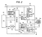
- Figure 2 shows a configuration of the solenoid control circuit of the controller of the internal combustion engine in Figure 1 .
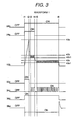
- Figure 3 shows a first current wave of the injector driving generated by the solenoid control circuit in Figure 2 .
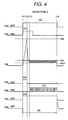
- Figure 4 shows a second current wave of the injector driving generated by the solenoid control circuit in Figure 2 .
- Figure 5 shows a third current wave of the injector driving generated by the solenoid control circuit in Figure 2 .
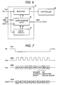
- Figure 6 shows an internal block diagram of the SPI in the solenoid control circuit in Figure 2 .
- Figure 7 shows a bit allocation map of the SPI in Figure 6 .
- Figure 8 shows a control flowchart of the controller of the internal combustion engine in Figure 1 .
- FIG. 1 shows an entire configuration of an internal combustion engine system to which a controller of an internal combustion engine having a fuel injection system according to the present invention is applied.
- an internal combustion engine 1 is a multi-cylinder internal combustion engine which comprises a spark plug 17a fired by a ignition coil 17, a fuel injection valve (injector) 13 for injecting a fuel directly into the cylinder, and a fuel pump 12 for compressing and sending a fuel to the fuel injection valve 13 from a fuel tank 11.
- Each cylinder 1a of the internal combustion engine 1 is supplied with an intake air which enters an inlet 4 of an air cleaner 3, passing through an air meter (air-flow sensor) 5 which is one of measurement means for the operation condition of the internal combustion engine 1, a throttle body 7 containing a throttle valve 6 for the intake air flow control, and a collector 8.
- the intake air is distributed to an intake air pipe 19 connected to each cylinder 1a of the internal combustion engine 1 before entering a combustion chamber 2 of the cylinder 1a.
- the throttle valve 6 is connected to a motor 10.
- the motor 10 is driven to operate the throttle valve 6 for the intake air flow control.
- the combustion chamber 2 of the cylinder 1a emits a combustion exhaust gas which is released outside through an exhaust pipe 23.
- the fuel such as a gasoline from the fuel tank 11 is sucked and compressed by the fuel pump 12.
- the fuel is then regulated at a predetermined pressure by a variable fuel pressure regulator 14.
- the fuel is then injected into the combustion chamber 2 of each cylinder 1a from the injector 13.
- the injector 13 exposes its fuel injection nozzle to the combustion chamber 2.
- the variable fuel pressure regulator 14 is controlled by a control unit 15.
- the air meter 5 sends a signal indicative of the intake air flow to the control unit 15.
- the throttle body 7 is provided with a throttle sensor 18. The sensor 18 detects the opening of the throttle valve 6 and sends the detection signal to the control unit 15.
- the internal combustion engine 15 also has a crank angle sensor 16.
- the crank angle sensor 16 is rotated by a camshaft 22 and sends a signal indicative of the rotational position of the crankshaft to the control unit 15.
- the exhaust pipe 23 has a A/F (Air Fuel Ratio) sensor 20.
- the A/F (Air Fuel Ratio) sensor 20 detects the air fuel ratio in actual driving according to the constituents of the exhaust gas in the exhaust pipe 23.
- the A/F sensor 20 sends the detection signal to the control unit 15.
- the throttle body 7 has an integrated acceleration sensor 9 which is connected to an acceleration pedal 12.
- the acceleration sensor 9 detects the operating amount of the driver on the acceleration pedal 12 and sends the detection signal to the control unit 15.
- the control unit 15 has a processing means (CPU) 24.
- the processing means 24 receives input signals from, for example, several sensors for detecting the operation condition of the internal combustion engine such as the above described crank angle signal and acceleration opening signal.
- the processing means 24 then performs an operation on the signals and sends predetermined control signals to the above described injector 13, ignition coil 17, and motor 10 for operating the throttle valve 6 and thus controls the fuel supply, ignition timing, and intake air flow.
- the variable fuel pressure regulator 14 in the fuel system has an adjacent fuel pressure sensor 21.
- the fuel pressure sensor 21 sends a signal to the control unit 15. Between the power supply (battery) 25 and the control unit 15, is provided an ignition switch 26.
- the injector 13 injects the fuel into the combustion chamber 2 of the cylinder 1a as described above.
- the injector 13 includes therein a plunger (not shown), a solenoid for energizing the plunger in a valve opening direction (see Fig. 2 ), and a spring for energizing the plunger in a valve closing direction.
- the injector 13 is supplied with a very high fuel pressure which also energizes the plunger in a valve opening direction.
- Fig. 2 shows a configuration of the control circuit of the injector 13 in the control unit 15.
- the control circuit 31 (solenoid control means) for the solenoid 13a in the injector 13 has a circuits group.
- the circuits group comprises a boost circuit 32 for generating a higher voltage than the battery voltage 26a, a power from the battery 25.
- the opening of the injector 13 needs a large magnetmotive force of the solenoid 13a.
- the force of the solenoid 13a is insufficient to open the injector 13.
- the above described boost circuit 32 is needed.
- a first switching device 33 controls a supply and interruption of a current to apply the boosted voltage 32a generated at the boost circuit 32 to the injector 13 (solenoid 13a).
- a second switching device 34 controls a supply and interruption of the current to apply the power 26a from the battery 26 to the injector 13.
- the power supply (current) from the first switching device 33 and second switching device 34 are wired OR on a signal line 35a.
- the voltages on the line 35a have a relationship of the boosted voltage 32a > the battery voltage 26a, so that the boosted voltage 32a may flow into the battery 25 through the switching devices 33, 34.
- a current backflow prevention device 35 is provided between the signal line 35a and the second switching device 34.
- Third and forth switching devices 36, 37 sink the current from the injector 13 to the ground and are provided for each injector separately.
- a feedback device 38 is for making a flywheel circuit which cycles the current across the injector 13 through the third switching device 36 (or the forth switching device 37) ⁇ the ground ⁇ feedback device 38 ⁇ injector 13.
- the above described first switching device 33, second switching device 34, current backflow prevention device 35, and feedback device 38 are provided for each couple of the opposed cylinders of the injector 13.
- the above described first switching device 33, second switching device 34, current backflow prevention device 35, and feedback device 38 are provided for each injector 13 separately.
- a reference current generator 40 sets a reference current for the injector 13.
- the reference current is set at three levels of a valve opening current 40a, holding current 40b, and holding current 40c.
- a controller 39 controls the above described switching devices 33, 34, 36, and 37.
- the controller 39 selects one of the three reference currents 40a, 40b, and 40c according to the stage of the current supply to the injector 13 and switches to the selected current.
- the interface between the CPU 24 and the solenoid control circuit 31 consists of parallel inputs 24a, 24b, and serial communication 24c.
- the CPU 24 sends the valve opening signal 24a and holding signal 24b to the controller 39 according to the fuel injection pulse width calculated in the CPU 24.
- the serial communication 24c the CPU 24 communicates with a serial peripheral interface (SPI) 42 in the solenoid control circuit 31 to switch between the injector driving current waveforms in the controller 39.
- SPI serial peripheral interface
- the controller 39, SPI 42, and the reference current generator 40 are collectively called a current waveform control means.
- Figs. 3-5 show the control signals for each component to drive and control the injector 13 (solenoid 13a), and the injector driving current waveforms (solenoid current waveforms).
- the injector driving current waveforms (solenoid current waveforms) have three types of waveforms 1-3.
- the CPU can switch between the waveforms 1-3 via the SPI communication according to the operating condition.
- the injector driving current waveform (solenoid current waveform) 13b shown in Fig. 2 will be described. Following description will be given for the third switching device 36 for sinking the current, although the same description can be applied to the forth switching device 37 for sinking the current.
- the waveform 1 in Fig. 3 has a valve opening current and two stages of a holding current as shown by the injector driving current waveform 13b.
- Timing t1 is a timing when the injector 13 starts the fuel injection.
- the first switching device 33 and third switching device 36 are turned on, and the injector driving current 13b flows through the first switching device 33 ⁇ the injector 13 ⁇ the third switching device 36 ⁇ the ground, and the driving current 13b for valve opening is supplied to the injector 13 up to a predetermined current value 40a to open the injector 13.
- the injector driving current 13b is detected by a current detection device provided in the third switching device 36.
- the detected current value 36y is compared with the reference value 40a of the valve opening current.
- the first switching device 33 and third switching device 36 are controlled by the control signal 33z and 36z from the controller, respectively.
- the first switching device 33 is turned off so that the injector driving current 13b reduces with flowing through a current loop of the injector 13 ⁇ the third switching device 36 ⁇ the ground ⁇ the feedback device 38 ⁇ the injector 13.
- the second switching device 34 is turned on by a control signal 34z from the controller 39. Then the injector driving current 13b flows through the second switching device 34 ⁇ the current backflow prevention device 35 ⁇ the injector 13 ⁇ the third switching device 36 ⁇ the ground. The second switching device 34 is left on until the injector driving current 13b reaches a predetermined current value 40b. At this time, the injector driving current 13b is detected by a current detection device provided in the third switching device 36. The detected current value 36y is compared with the reference vale 40b of the holding current 1 and the hiss reference value 40b1 of the holding current 1 which is determined by the reference current 40b of the holding current 1.
- the above described second switching device 34 is repeatedly turned on/off to perform a constant current control of the injector driving current 13b within a predetermined current value of 40b1-40b.
- the controlled constant current value according to the present embodiment is set as to increase the suction force when the valve opening current can not open the injector 13 for the higher fuel pressure.
- the constant current value is set at a relatively large value to increase the magnetmotive force of the solenoid 13a in the injector 13 and open the injector 13.
- the second switching device 34 is turned on by a control signal 34z from the controller 39. Then the injector driving current 13b flows through the second switching device 34 ⁇ the current backflow prevention device 35 ⁇ the injector 13 ⁇ the third switching device 36 ⁇ the ground. The second switching device 34 is left on until the injector driving current 13b reaches a predetermined current value 40c. At this time, the injector driving current 13b is detected by a current detection device provided in the third switching device 36. The detected current value 36y is compared with the reference vale 40c of the holding current 2 and the hiss reference value 40c1 of the holding current 2 which is determined by the reference current 40c of the holding current. During the period of t5-t6 before the holding signal 24b is turned off, the above described second switching device 34 is repeatedly turned on/off to perform a constant current control of the injector driving current 13b within a predetermined current value of 40c1-40c.
- the injector driving current 13b is interrupted and the fuel injection is stopped.
- the second switching device 34 and third switching device 36 are turned off, that is to say, both switching devices for controlling the current flows upstream and downstream to the injector 13 are stopped.
- the injector driving current 13b quickly reduces and the fuel injection from the injector 13 stops in response to the holding signal 24b.
- the waveform 2 in Fig. 4 has a valve opening current and one stage of the holding current as shown by the injector driving current waveform 13b.
- Timing t11 is a timing when the injector 13 starts the fuel injection.
- the first switching device 33 and third switching device 36 are turned on, and the injector driving current 13b flows through the first switching device 33 ⁇ the injector 13 ⁇ the third switching device 36 ⁇ the ground, and the valve opening current 13b is supplied to the injector 13 up to a predetermined current value 40a to open the injector 13.
- the injector driving current 13b is detected by a current detection device provided in the third switching device 36.
- the detected current value 36y is compared with the reference value 40a of the valve opening current.
- the first switching device 33 is turned off so that the injector driving current 13b reduces with flowing through a current loop of the injector 13 ⁇ the third switching device 36 ⁇ the ground ⁇ the feedback device 38 ⁇ the injector 13.
- the second switching device 34 is turned on by a control signal 34z from the controller 39. Then the injector driving current 13b flows through the second switching device 34 ⁇ the current backflow prevention device 35 ⁇ the injector 13 ⁇ the third switching device 36 ⁇ the ground. The second switching device 34 is left on until the injector driving current 13b reaches a predetermined current value 40c. At this time, the injector driving current 13b is detected by a current detection device provided in the third switching device 36. The detected current value 36y is compared with the reference vale 40c of the holding current 2 and the hiss reference value 40c1 of the holding current 1 which is determined by the reference current 40c of the holding current 2.
- the above described second switching device 34 is repeatedly turned on/off to perform a constant current control of the injector driving current 13b within a predetermined current value of 40c1-40c.
- the controlled constant current value according to the present embodiment is set in the same way as during the period of t5-t6 in Fig. 3 , that is to say, to hold the opening state of the injector 13.
- the injector driving current 13b is interrupted and the fuel injection is stopped.
- the second switching device 34 and third switching device 36 are turned off, that is to say, both switching devices for controlling the current flows upstream and downstream to the injector 13 are stopped.
- the injector driving current 13b quickly reduces and the fuel injection from the injector 13 stops in response to the holding signal 24b.
- the valve opening signal 24a is only used as a condition for allowing the start of the valve opening current.
- the valve opening signal 24a can have an off timing anytime during the period of t12-t14.
- the waveform 2 differs from the waveform 1 in that the waveform 2 does not have the holding current 1.
- the waveform 3 in Fig. 5 has a valve opening current and one stage of the holding current as shown by the injector driving current waveform 13b.
- the waveform 3 differs from the waveform 2 in that the third downstream switching device 36 is turned off during switching from the valve opening current to the holding current.
- Timing t21 is a timing when the injector 13 starts the fuel injection.
- the first switching device 33 and third switching device 36 are turned on, and the injector driving current 13b flows through the first switching device 33 ⁇ the injector 13 ⁇ the third switching device 36 ⁇ the ground, and the injector driving current 13b is supplied to the injector 13 up to a predetermined current value 40a to open the injector 13.
- the injector driving current 13b is detected by a current detection device provided in the third switching device 36. The detected current value 36y is compared with the reference value 40a of the valve opening current.
- the first switching device 33 and third switching device 36 are turned off so that the injector driving current 13b quickly reduces.
- the third switching device 36 has a loss of the injector driving current 13b between t22-t23 x the voltage 36a.
- the injector driving current 13b is the valve opening current 40a which is large and causes a very large circuit loss.
- the second switching device 34 and the third switching device 36 are turned on by the control signals 34z, 36z from the controller 39, respectively. Then the injector driving current 13b flows through the second switching device 34 ⁇ the current backflow prevention device 35 ⁇ the injector 13 ⁇ the third switching device 36 ⁇ the ground. The second switching device 34 is left on until the injector driving current 13b reaches a predetermined current value 40c. At this time, the injector driving current 13b is detected by a current detection device provided in the third switching device 36.
- the detected current value 36y is compared with the reference vale 40c of the holding current 2 and the hiss reference value 40c1 of the holding current 1 which is determined by the reference current 40c of the holding current 2.
- the above described second switching device 34 is repeatedly turned on/off to perform a constant current control of the injector driving current 13b within a predetermined current value of 40c1-40c.
- the controlled constant current value according to the present embodiment is set in the same way as during the period of t5-t6 in Fig. 3 and the period of t13-t14 in Fig. 4 , that is to say, to hold the opening state of the injector 13.
- the injector driving current 13b is interrupted and the fuel injection is stopped.
- the second switching device 34 and third switching device 36 are turned off, that is to say, both switching devices for controlling the current flows upstream and downstream to the injector 13 are stopped.
- the injector driving current 13b quickly reduces and the fuel injection from the injector 13 stops in response to the holding signal 24b.
- the valve opening signal 24a is only used as a condition for allowing the start of the valve opening current.
- the valve opening signal 24a can have an off timing anytime during the period of t22-t24.
- the waveform 3 differs from the waveform 2 in that the third downstream switching device 36 is turned off in switching from the valve opening current to the holding current.
- Each waveform has merits and demerits.
- Qmin property The property of minimum effective fuel injection pulse width (Qmin property) is in the following order for each current waveform. waveform 3 > waveform 2 > waveform 1
- the waveform 3 needs to be used for the injector control.
- the circuit loss of the injector control circuit 31 is in the following order from lowest to highest for each waveform. waveform 2 > waveform 1 > waveform 3
- the waveform 2 results in the minimum circuit loss so that the waveform 2 of the injector driving current waveform is preferably used for the injector control, except in the above described operation area where the Qmin property is important and except when the large suction force is necessary for the higher fuel pressure.
- the waveform 2 is also necessary to decrease the total loss of the control unit 15.
- the waveform of the injector driving current 13b is switched to the optimum waveform for each operation state to realize both the good property of the injector 13 and the lower loss of the injector control circuit 31.
- Fig. 6 shows an internal block diagram of the SPI communication 42 which switches the injector driving current 13b according to the present embodiment.
- the SPI communication line 24c which is shown as one line in Fig. 2 , has four lines of CS line 24c1, DIN line 24c2, SCK line 24c3, and DOUT line 24c4.
- the transmission and reception of the serial communication are performed between the CPU 24 and the SPI 42 in the injector controller 31.
- the signal input from the CS line 24c1 confirms 8 bit data which is previously stored in a latch circuit 63 and copy them to a shift register 62.
- the latch circuit 63 and the signal from the DOUT line 24c4 are not particularly described.
- the serial communication between the CPU 24 and the SPI 42 consists of the 8 bit shift register 62.
- the signals from the DIN line 24c2 of the CPU 24 are stored in the register 62.
- the transmission data stored in the shift register 62 is flushed as signals on the DOUT line 24c4 in response to the signal on the SCK line 24c3.
- the data stored in the shift register 62 is moved to the register 61 when the signals from the CS line 24c1 are completed (the signal is HIGH).
- the signals from the DIN line 24c2 include commands for switching between the injector driving currents waveforms.
- the 8 bit signals from the DIN line 24c2 include 2 bits to be able to switch among three type waveforms.
- the controller 39 extracts the commands for switching among the injector driving current waveforms from the received signals from the DIN line 24c2.
- the controller 39 then controls the injector driving current 13b according to the commands.
- the above described SPI communication which has been described as the 8 bit shift register, can consist of any bit shift register such as a 16 bit shift register.
- Fig. 7 shows a bit allocation map of the SPI communication.
- the signals from the DIN line 24c2 are 8 bits data and 2 bits are allocated to the signals as bits for switching between the injector driving current waveforms.
- the injector driving current waveforms and the signals from the DIN line 24c2 have the following relationship.
- Fig. 8 shows a flowchart of software in the CPU 24, which can realize a means for switching between the injector driving current waveforms according to the present embodiment.
- the present task is generally a regular job which is, for example, performed every 10 ms.
- the 10 ms task is called, and started at START of step S1.
- step S2 it is checked whether the injector is injecting at present.
- the switching between the injector driving current waveforms during the injection of the injector will result in an abnormal injection operation.
- the means for switching between the injector driving current waveforms is masked during the injection of the injector, in other word, jump to END of step S9.
- step S2 if it is checked that the injector is not injecting, jump to step S3.
- step S3 it is checked whether the present operation condition of the internal combustion engine is in the area where the Qmin property is important. If the operation condition is in the area where the Qmin property is important, jump to step S5.
- step S3 if the operation condition is not in the area where the Qmin property is important, jump to step S4.
- step S4 it is checked whether the present operation condition of the internal combustion engine is under the higher fuel pressure. If the operation condition is under the higher fuel pressure, then jump to step S6.
- step S4 if the operation condition is not under the higher fuel pressure, jump to step S7.
- step S8 the injector driving current waveforms which are set at the above described steps S5, S6, and S7 are sent to the injector control circuit 31 via the SPI communication.
- the injector driving current waveforms are set in the controller 39 via the SPI 42.
- the amount of the fuel injection is determined according to the valve opening signal 24a and the pulse width of the holding signal 24b and the internal combustion engine 1 is optimally controlled.
- a controller for an internal combustion engine having a fuel injection system can optimally control the injector even for a higher fuel pressure with a smaller inductance of the solenoid due to the smaller injector, and can keep a good property of minimum amount of fuel injection, and can also decrease the loss of the fuel supply system of the internal combustion engine.
Landscapes
- Engineering & Computer Science (AREA)
- Chemical & Material Sciences (AREA)
- Combustion & Propulsion (AREA)
- Mechanical Engineering (AREA)
- General Engineering & Computer Science (AREA)
- Fuel-Injection Apparatus (AREA)
- Electrical Control Of Air Or Fuel Supplied To Internal-Combustion Engine (AREA)
- Magnetically Actuated Valves (AREA)
Applications Claiming Priority (2)
| Application Number | Priority Date | Filing Date | Title |
|---|---|---|---|
| JP2001302694 | 2001-09-28 | ||
| JP2001302694A JP4037632B2 (ja) | 2001-09-28 | 2001-09-28 | 燃料噴射装置を備えた内燃機関の制御装置 |
Publications (3)
| Publication Number | Publication Date |
|---|---|
| EP1298305A2 EP1298305A2 (en) | 2003-04-02 |
| EP1298305A3 EP1298305A3 (en) | 2006-06-28 |
| EP1298305B1 true EP1298305B1 (en) | 2011-05-18 |
Family
ID=19122891
Family Applications (1)
| Application Number | Title | Priority Date | Filing Date |
|---|---|---|---|
| EP02006548A Expired - Lifetime EP1298305B1 (en) | 2001-09-28 | 2002-03-20 | Controller for internal combustion engine having fuel injection system |
Country Status (3)
| Country | Link |
|---|---|
| US (1) | US6684862B2 (ja) |
| EP (1) | EP1298305B1 (ja) |
| JP (1) | JP4037632B2 (ja) |
Families Citing this family (31)
| Publication number | Priority date | Publication date | Assignee | Title |
|---|---|---|---|---|
| JP2004092573A (ja) * | 2002-09-03 | 2004-03-25 | Hitachi Ltd | 燃料噴射装置および制御方法 |
| JP3894088B2 (ja) * | 2002-10-07 | 2007-03-14 | 株式会社日立製作所 | 燃料供給装置 |
| ITTO20030939A1 (it) * | 2003-11-25 | 2005-05-26 | Fiat Ricerche | Dispositivo di comando di elettroattuatori induttivi. |
| ITTO20030940A1 (it) * | 2003-11-25 | 2005-05-26 | Fiat Ricerche | Dispositivo di comando di elettroiniettori di un impianto di iniezione del combustibile a collettore comune per un motore a combustione interna. |
| US20060275137A1 (en) * | 2005-06-01 | 2006-12-07 | Visteon Global Technologies, Inc. | Fuel pump boost system |
| JP2007170204A (ja) * | 2005-12-19 | 2007-07-05 | Kokusan Denki Co Ltd | 内燃機関用燃料噴射装置 |
| JP4353211B2 (ja) * | 2006-07-11 | 2009-10-28 | 株式会社日立製作所 | 通信機能内蔵制御装置 |
| JP4474423B2 (ja) * | 2007-01-12 | 2010-06-02 | 日立オートモティブシステムズ株式会社 | 内燃機関制御装置 |
| JP2008291778A (ja) * | 2007-05-25 | 2008-12-04 | Denso Corp | 電磁弁制御装置 |
| JP4917556B2 (ja) * | 2008-01-07 | 2012-04-18 | 日立オートモティブシステムズ株式会社 | 内燃機関の燃料噴射制御装置 |
| WO2009154214A1 (ja) * | 2008-06-19 | 2009-12-23 | ボッシュ株式会社 | 燃料噴射弁の制御装置、制御方法、及び制御プログラム |
| JP4815502B2 (ja) | 2009-03-26 | 2011-11-16 | 日立オートモティブシステムズ株式会社 | 内燃機関の制御装置 |
| CN101857356B (zh) | 2009-04-07 | 2014-03-26 | 尼普洛株式会社 | 用于生产医用玻璃容器的方法和用于医用玻璃容器的内表面处理的燃烧器 |
| JP5058239B2 (ja) * | 2009-10-30 | 2012-10-24 | 日立オートモティブシステムズ株式会社 | 内燃機関の燃料噴射制御装置 |
| DE102009056802B4 (de) * | 2009-12-03 | 2019-05-29 | Robert Bosch Gmbh | Ansteuerelektronik für ein elektromagnetisch betätigtes Ventil zum Betrieb einer hydrostatischen Verdrängereinheit |
| FR2955516B1 (fr) * | 2010-01-26 | 2012-04-20 | Prospection & Inventions | Procede de commande d'un outil a moteur a combustion interne et l'outil ainsi commande |
| JP5198496B2 (ja) | 2010-03-09 | 2013-05-15 | 日立オートモティブシステムズ株式会社 | 内燃機関のエンジンコントロールユニット |
| JP5300787B2 (ja) * | 2010-05-31 | 2013-09-25 | 日立オートモティブシステムズ株式会社 | 内燃機関制御装置 |
| JP5358621B2 (ja) | 2011-06-20 | 2013-12-04 | 日立オートモティブシステムズ株式会社 | 燃料噴射装置 |
| US9103295B2 (en) * | 2012-08-13 | 2015-08-11 | Continental Automotive Systems, Inc. | Current controller having programmable current-control parameters and hardware-implemented support functions |
| JP5975899B2 (ja) * | 2013-02-08 | 2016-08-23 | 日立オートモティブシステムズ株式会社 | 燃料噴射装置の駆動装置 |
| WO2014189527A1 (en) * | 2013-05-24 | 2014-11-27 | International Engine Intellectual Property Company, Llc | Injector waveform |
| US9347395B2 (en) * | 2013-08-22 | 2016-05-24 | GM Global Technology Operations LLC | Method for improving closely-spaced multiple-injection performance from solenoid actuated fuel injectors |
| JP5875559B2 (ja) * | 2013-08-30 | 2016-03-02 | 日立オートモティブシステムズ株式会社 | 燃料噴射装置の駆動回路 |
| EP2918816B1 (en) * | 2014-03-14 | 2017-09-06 | Continental Automotive GmbH | Fuel injector |
| US10401398B2 (en) | 2017-03-03 | 2019-09-03 | Woodward, Inc. | Fingerprinting of fluid injection devices |
| JP7110736B2 (ja) * | 2018-05-31 | 2022-08-02 | 株式会社デンソー | 燃料噴射弁の制御装置、及び燃料噴射システム |
| US10900391B2 (en) * | 2018-06-13 | 2021-01-26 | Vitesco Technologies USA, LLC. | Engine control system and method for controlling activation of solenoid valves |
| US20200025122A1 (en) * | 2018-07-17 | 2020-01-23 | Continental Automotive Systems, Inc. | Engine control system and method for controlling activation of solenoid valves |
| KR20210104317A (ko) * | 2020-02-17 | 2021-08-25 | 현대자동차주식회사 | 인젝터 열림 시간 편차 개선을 위한 연료 분사 제어 장치 및 방법 |
| US11795886B2 (en) * | 2021-12-13 | 2023-10-24 | Caterpillar Inc. | Reduced energy waveform for energizing solenoid actuator in fuel injector valve |
Family Cites Families (19)
| Publication number | Priority date | Publication date | Assignee | Title |
|---|---|---|---|---|
| JPS5681232A (en) * | 1979-12-04 | 1981-07-03 | Aisan Ind Co Ltd | Valve driving mechanism and its control for injector |
| JPS5872646A (ja) * | 1981-10-26 | 1983-04-30 | Toyota Motor Corp | 内燃機関の空燃比制御方法 |
| JPS60135646A (ja) * | 1983-12-21 | 1985-07-19 | Ngk Spark Plug Co Ltd | 弁開閉制御用ソレノイド付燃料噴射装置の燃料噴射開始時期制御用信号発生装置 |
| US4922878A (en) * | 1988-09-15 | 1990-05-08 | Caterpillar Inc. | Method and apparatus for controlling a solenoid operated fuel injector |
| JPH033945A (ja) * | 1989-05-31 | 1991-01-10 | Hitachi Ltd | エンジン制御装置 |
| JP3052572B2 (ja) * | 1992-05-21 | 2000-06-12 | 株式会社デンソー | 内燃機関の燃料噴射制御装置 |
| JP3286371B2 (ja) * | 1993-02-15 | 2002-05-27 | 本田技研工業株式会社 | 内燃機関の燃料噴射制御装置 |
| US5701870A (en) * | 1996-04-15 | 1997-12-30 | Caterpillar Inc. | Programmable fuel injector current waveform control and method of operating same |
| US5788154A (en) * | 1996-05-02 | 1998-08-04 | Caterpillar Inc. | Method of preventing cavitation in a fuel injector having a solenoid actuated control valve |
| JP3613885B2 (ja) * | 1996-05-24 | 2005-01-26 | 国産電機株式会社 | 内燃機関用インジェクタの駆動制御方法及び駆動制御装置 |
| JPH1113519A (ja) | 1997-06-19 | 1999-01-19 | Nissan Motor Co Ltd | 燃料噴射弁の駆動制御装置の診断装置及び該診断装置の診断装置 |
| DE19728840A1 (de) * | 1997-07-05 | 1999-01-07 | Bosch Gmbh Robert | Verfahren und Vorrichtung zur Erfassung eines Schaltzeitpunktes eines Magnetventils |
| JP3871168B2 (ja) | 1998-06-03 | 2007-01-24 | 株式会社日立製作所 | エンジン燃料供給診断装置、該診断方法および燃料供給装置 |
| JP3932474B2 (ja) * | 1999-07-28 | 2007-06-20 | 株式会社日立製作所 | 電磁式燃料噴射装置及び内燃機関 |
| JP2001152940A (ja) * | 1999-11-24 | 2001-06-05 | Mitsubishi Electric Corp | 燃料噴射システム |
| JP2001221121A (ja) * | 2000-02-08 | 2001-08-17 | Hitachi Ltd | 電磁式燃料噴射装置及びこれを搭載した内燃機関 |
| JP4168567B2 (ja) * | 2000-03-02 | 2008-10-22 | 株式会社デンソー | 電磁弁駆動装置 |
| JP2001317394A (ja) * | 2000-04-28 | 2001-11-16 | Mitsubishi Electric Corp | 筒内噴射エンジンの燃料噴射制御装置 |
| JP4110751B2 (ja) * | 2001-06-18 | 2008-07-02 | 株式会社日立製作所 | インジェクタ駆動制御装置 |
-
2001
- 2001-09-28 JP JP2001302694A patent/JP4037632B2/ja not_active Expired - Lifetime
-
2002
- 2002-03-20 EP EP02006548A patent/EP1298305B1/en not_active Expired - Lifetime
- 2002-03-20 US US10/101,207 patent/US6684862B2/en not_active Expired - Lifetime
Also Published As
| Publication number | Publication date |
|---|---|
| US20030062029A1 (en) | 2003-04-03 |
| JP4037632B2 (ja) | 2008-01-23 |
| US6684862B2 (en) | 2004-02-03 |
| EP1298305A2 (en) | 2003-04-02 |
| JP2003106200A (ja) | 2003-04-09 |
| EP1298305A3 (en) | 2006-06-28 |
Similar Documents
| Publication | Publication Date | Title |
|---|---|---|
| EP1298305B1 (en) | Controller for internal combustion engine having fuel injection system | |
| JP4083571B2 (ja) | 内燃機関を動作させる方法 | |
| EP0947686B1 (en) | Fuel-injection system for engine | |
| US6895933B2 (en) | Ignition and injection control system for internal combustion engine | |
| JP3885888B2 (ja) | コモンレールシステム | |
| EP1728997A2 (en) | Control apparatus of fuel injection type internal combustion engine | |
| JP3175426B2 (ja) | 内燃機関の燃料噴射装置 | |
| WO2002006657A9 (en) | Method and apparatus for delivering multiple fuel injections to the cylinder of an internal combustion engine | |
| JP2010255444A (ja) | 内燃機関の燃料噴射制御装置及び方法 | |
| US5893352A (en) | Cylinder injection type fuel control apparatus | |
| US7856867B2 (en) | Injector control performance diagnostic systems | |
| US6973919B2 (en) | Internal combustion engine and method, computer program and control apparatus for operating the internal combustion engine | |
| JPS61229957A (ja) | 燃料制御装置 | |
| JP4426652B2 (ja) | 油圧作動式電子制御燃料噴射システムの異なった種類の噴射波形使用の移行を制御する方法 | |
| US5878713A (en) | Fuel control system for cylinder injection type internal combustion engine | |
| US6450149B1 (en) | Method and apparatus for controlling overlap of two fuel shots in multi-shot fuel injection events | |
| JPH06330797A (ja) | エンジンの燃料噴射弁駆動回路 | |
| JP2004144086A (ja) | 燃料噴射システムの分割モード動作 | |
| JP5123251B2 (ja) | アクチュエータ制御装置 | |
| US5947078A (en) | Fuel control system for cylinder injection type internal combustion engine | |
| US7497206B2 (en) | Method for operating an internal combustion engine | |
| US5970955A (en) | Fuel injection control method and system in a cylinder-inside direct injection type spark ignition combustion engine | |
| RU2265745C2 (ru) | Способ и устройство управления впрыскиванием топлива в двигатель внутреннего сгорания | |
| GB2165586A (en) | Fuel control system | |
| KR100569314B1 (ko) | 커먼레인 디젤엔진의 파일럿 분사량 제어 방법 |
Legal Events
| Date | Code | Title | Description |
|---|---|---|---|
| PUAI | Public reference made under article 153(3) epc to a published international application that has entered the european phase |
Free format text: ORIGINAL CODE: 0009012 |
|
| AK | Designated contracting states |
Kind code of ref document: A2 Designated state(s): AT BE CH CY DE DK ES FI FR GB GR IE IT LI LU MC NL PT SE TR Designated state(s): AT BE CH CY DE DK ES FI FR GB GR IE IT LI LU MC NL PT SE TR |
|
| AX | Request for extension of the european patent |
Extension state: AL LT LV MK RO SI |
|
| PUAL | Search report despatched |
Free format text: ORIGINAL CODE: 0009013 |
|
| AK | Designated contracting states |
Kind code of ref document: A3 Designated state(s): AT BE CH CY DE DK ES FI FR GB GR IE IT LI LU MC NL PT SE TR |
|
| AX | Request for extension of the european patent |
Extension state: AL LT LV MK RO SI |
|
| RIC1 | Information provided on ipc code assigned before grant |
Ipc: F02D 41/14 20060101ALI20060523BHEP Ipc: F02D 41/20 20060101AFI20030113BHEP Ipc: F02D 41/18 20060101ALI20060523BHEP Ipc: F02D 41/02 20060101ALI20060523BHEP |
|
| 17P | Request for examination filed |
Effective date: 20061228 |
|
| AKX | Designation fees paid |
Designated state(s): DE FR GB IT |
|
| 17Q | First examination report despatched |
Effective date: 20071122 |
|
| GRAP | Despatch of communication of intention to grant a patent |
Free format text: ORIGINAL CODE: EPIDOSNIGR1 |
|
| RAP1 | Party data changed (applicant data changed or rights of an application transferred) |
Owner name: HITACHI, LTD. |
|
| GRAS | Grant fee paid |
Free format text: ORIGINAL CODE: EPIDOSNIGR3 |
|
| GRAA | (expected) grant |
Free format text: ORIGINAL CODE: 0009210 |
|
| RAP1 | Party data changed (applicant data changed or rights of an application transferred) |
Owner name: HITACHI, LTD. |
|
| AK | Designated contracting states |
Kind code of ref document: B1 Designated state(s): DE FR GB IT |
|
| REG | Reference to a national code |
Ref country code: GB Ref legal event code: FG4D |
|
| REG | Reference to a national code |
Ref country code: DE Ref legal event code: R096 Ref document number: 60240050 Country of ref document: DE Effective date: 20110630 |
|
| PLBE | No opposition filed within time limit |
Free format text: ORIGINAL CODE: 0009261 |
|
| STAA | Information on the status of an ep patent application or granted ep patent |
Free format text: STATUS: NO OPPOSITION FILED WITHIN TIME LIMIT |
|
| 26N | No opposition filed |
Effective date: 20120221 |
|
| REG | Reference to a national code |
Ref country code: DE Ref legal event code: R097 Ref document number: 60240050 Country of ref document: DE Effective date: 20120221 |
|
| PGFP | Annual fee paid to national office [announced via postgrant information from national office to epo] |
Ref country code: IT Payment date: 20130509 Year of fee payment: 13 |
|
| PG25 | Lapsed in a contracting state [announced via postgrant information from national office to epo] |
Ref country code: IT Free format text: LAPSE BECAUSE OF NON-PAYMENT OF DUE FEES Effective date: 20150320 |
|
| REG | Reference to a national code |
Ref country code: FR Ref legal event code: PLFP Year of fee payment: 15 |
|
| REG | Reference to a national code |
Ref country code: FR Ref legal event code: PLFP Year of fee payment: 16 |
|
| REG | Reference to a national code |
Ref country code: FR Ref legal event code: PLFP Year of fee payment: 17 |
|
| PGFP | Annual fee paid to national office [announced via postgrant information from national office to epo] |
Ref country code: FR Payment date: 20210210 Year of fee payment: 20 |
|
| PGFP | Annual fee paid to national office [announced via postgrant information from national office to epo] |
Ref country code: DE Payment date: 20210310 Year of fee payment: 20 Ref country code: GB Payment date: 20210310 Year of fee payment: 20 |
|
| REG | Reference to a national code |
Ref country code: DE Ref legal event code: R071 Ref document number: 60240050 Country of ref document: DE |
|
| REG | Reference to a national code |
Ref country code: GB Ref legal event code: PE20 Expiry date: 20220319 |
|
| PG25 | Lapsed in a contracting state [announced via postgrant information from national office to epo] |
Ref country code: GB Free format text: LAPSE BECAUSE OF EXPIRATION OF PROTECTION Effective date: 20220319 |