EP1298303A2 - Verfahren und Steuer- und/oder Regelgerät zum Betreiben einer Brennkraftmaschine, sowie Brennkraftmaschine - Google Patents
Verfahren und Steuer- und/oder Regelgerät zum Betreiben einer Brennkraftmaschine, sowie Brennkraftmaschine Download PDFInfo
- Publication number
- EP1298303A2 EP1298303A2 EP02018418A EP02018418A EP1298303A2 EP 1298303 A2 EP1298303 A2 EP 1298303A2 EP 02018418 A EP02018418 A EP 02018418A EP 02018418 A EP02018418 A EP 02018418A EP 1298303 A2 EP1298303 A2 EP 1298303A2
- Authority
- EP
- European Patent Office
- Prior art keywords
- fuel
- internal combustion
- combustion engine
- pressure
- combustion chamber
- Prior art date
- Legal status (The legal status is an assumption and is not a legal conclusion. Google has not performed a legal analysis and makes no representation as to the accuracy of the status listed.)
- Granted
Links
Images

Classifications
-
- F—MECHANICAL ENGINEERING; LIGHTING; HEATING; WEAPONS; BLASTING
- F02—COMBUSTION ENGINES; HOT-GAS OR COMBUSTION-PRODUCT ENGINE PLANTS
- F02D—CONTROLLING COMBUSTION ENGINES
- F02D41/00—Electrical control of supply of combustible mixture or its constituents
- F02D41/30—Controlling fuel injection
- F02D41/38—Controlling fuel injection of the high pressure type
- F02D41/3809—Common rail control systems
- F02D41/3836—Controlling the fuel pressure
-
- F—MECHANICAL ENGINEERING; LIGHTING; HEATING; WEAPONS; BLASTING
- F02—COMBUSTION ENGINES; HOT-GAS OR COMBUSTION-PRODUCT ENGINE PLANTS
- F02D—CONTROLLING COMBUSTION ENGINES
- F02D41/00—Electrical control of supply of combustible mixture or its constituents
- F02D41/02—Circuit arrangements for generating control signals
- F02D41/04—Introducing corrections for particular operating conditions
- F02D41/06—Introducing corrections for particular operating conditions for engine starting or warming up
- F02D41/062—Introducing corrections for particular operating conditions for engine starting or warming up for starting
-
- F—MECHANICAL ENGINEERING; LIGHTING; HEATING; WEAPONS; BLASTING
- F02—COMBUSTION ENGINES; HOT-GAS OR COMBUSTION-PRODUCT ENGINE PLANTS
- F02D—CONTROLLING COMBUSTION ENGINES
- F02D2200/00—Input parameters for engine control
- F02D2200/02—Input parameters for engine control the parameters being related to the engine
- F02D2200/06—Fuel or fuel supply system parameters
- F02D2200/0602—Fuel pressure
Definitions
- the invention initially relates to a method for operating an internal combustion engine using fuel at least one fuel pump in a fuel rail is promoted from which he has at least a fuel injector directly in at least reaches a combustion chamber of the internal combustion engine.
- Such a process is known from the market. It will referred to as gasoline direct injection. With him the Fuel from a fuel tank from a first one Fuel pump (pre-feed pump) to a second Fuel pump (high pressure pump) promoted. This promotes the fuel into a fuel manifold ("rail"), in which the fuel is stored under high pressure. On the fuel rail are multiple fuel injectors connected to the fuel directly into the corresponding combustion chambers of the internal combustion engine inject.
- shift operation This means that only in Area of the spark plug an ignitable fuel-air mixture is present, whereas in the rest of the combustion chamber just a very lean air-fuel mixture or at all there is no fuel. This allows the Fuel consumption can be reduced. But it is also possible inject the fuel into the combustion chambers so that a homogeneous air-fuel mixture is present in the combustion chamber. Such an operating mode is called “homogeneous operation”. she is chosen especially at high loads and high speeds.
- a problem with internal combustion engines with gasoline direct injection is the start of the internal combustion engine: there the high pressure pump usually mechanically from the Internal combustion engine is driven and thus when standing Internal combustion engine itself stands, the pressure in the Fuel manifold of the internal combustion engine at the So far, usually only started from the electric driven pre-feed pump generated. This pressure is in the Generally only at 3-6 bar. With such a small one However, pressure is the atomization of the fuel by the fuel Fuel injector relatively poor. To do this To compensate, there is a certain amount of Additional fuel when starting the internal combustion engine injected to form an ignitable mixture in the combustion chamber Get internal combustion engine. This additional However, fuel mass leads to increased fuel consumption and worsens the emission properties the internal combustion engine.
- the present invention therefore has the task of a To further develop methods of the type mentioned at the beginning that when the engine starts, less fuel is consumed and the emission properties of the Engine get better.
- This task is initiated in a procedure mentioned kind in that the at the start of the Internal combustion engine with an injection from the Fuel injector in the combustion chamber Fuel mass to be injected from the pressure of the fuel rail depends.
- the start fuel mass to be injected from the current pressure in the Fuel rail made dependent.
- the Pressure in the fuel rail is higher than that of fuel pressure that can be generated by the pre-feed pump.
- there is pressure in the Fuel manifold builds up, which is higher than the pressure that can be generated by the pre-feed pump.
- the fuel will run out of fuel Fuel injector atomized better than in those situations in which only that from the pre-feed pump Generable pressure is present in the fuel rail. This means that the fuel is more ignitable and thus the fuel mass can be reduced. That will taken into account by the inventive method.
- the inventive method allows in many situations when starting the Internal combustion engine to reduce fuel consumption and to improve the emission behavior.
- the at the start of the internal combustion engine with an injection from the fuel injector into the combustion chamber fuel mass to be injected is formed in that a standard fuel mass is determined that at the start at a certain pressure in the fuel rail in the combustion chamber is to be injected, and this standard fuel mass multiplied by a weighting factor that is when the pressure in the fuel rail is equal to the determined pressure, the value 1 and if the pressure deviates from the determined one Pressure assumes a value not equal to 1.
- the standard fuel mass is by no means one Constant, but a fuel mass, which for example other parameters such as temperature the internal combustion engine, can depend. If the standard fuel mass for example the minimum pressure in the fuel rail is related - at this pressure it is preferably that of the prefeed pump generate pressure - then the weighting factor increases increasing pressure in the fuel rail a value less than 1.
- the injection may also take place in this during the compression cycle.
- the opening period of the fuel injector with an injection at the start of the internal combustion engine from that during an injection into the combustion chamber fuel mass to be injected and the pressure difference depends on the combustion chamber and fuel rail.
- Procedure is also proposed that only if in the fuel rail has a pressure of at least 20 bar, in particular at least about 50 bar, Fuel from the fuel injector into the Combustion chamber of the internal combustion engine is injected. This will build up the pressure in the fuel rail during the startup process of the Internal combustion engine accelerates because initially only fuel promoted in the fuel rail, but none Fuel is discharged from the fuel rail. It also ensures that a pressure in the Fuel rail, which is not sufficient Atomization of the fuel in the combustion chamber enables none Injection takes place. This will Fuel consumption of the internal combustion engine again reduced and the emission behavior during the start of the Internal combustion engine improved again.
- An "emergency circuit” can ensure that if the desired pressure even after a a certain time cannot be reached Injection at low pressure and correspondingly increased Amount of fuel.
- At least one Fuel pump at least to start the Internal combustion engine at least indirectly, electrically is driven.
- the pressure in the fuel rail exclusively by an electric driven fuel pump or by several electrically driven fuel pumps can already be generated during of the starting process of the internal combustion engine for the Atomization of sufficiently high pressure in a simple manner and Generated way.
- At least one fuel pump mechanically driven by the internal combustion engine and at Starting the internal combustion engine is an electric starter is operated.
- the electric starter works indirectly as an electric drive for the fuel pump.
- the Starter can be operated for a certain time to reduce the pressure to build up in the fuel rail. Only when the Pressure has reached a certain level, one takes place Fuel injection by the fuel injectors and its ignition in the combustion chamber.
- This method is also known in some Internal combustion engines without additional components realize. The advantages according to the invention can thus can be achieved without additional costs.
- the invention also relates to a computer program which suitable for performing the method of the above type is when it runs on a computer. Doing so particularly preferred if the computer program on a Memory, in particular on a flash memory or Ferrite RAM, is stored.
- the invention also relates to a control device for Operating an internal combustion engine.
- a control device for Operating an internal combustion engine With this one particularly preferred if it comprises a memory which a computer program of the above type is stored.
- the invention further relates to an internal combustion engine, with a fuel tank, with at least one Fuel pump which fuel from the Fuel tank in a fuel rail promotes, with at least one fuel injection device, which to the fuel rail is connected and fuel directly in at least one combustion chamber of the internal combustion engine injects, and with a pressure sensor, which the pressure in of the fuel rail.
- the Advantages of the invention can be achieved if they comprises a control and / or regulating device of the above type.
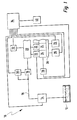
- an internal combustion engine carries this overall Reference numeral 10. It comprises a fuel tank 12, from which an electrically driven pre-feed pump 14 the Fuel into a low pressure fuel line 16 promotes.
- the low pressure fuel line 16 leads to one mechanically from a camshaft (not shown) the internal combustion engine driven high pressure fuel pump 18. This feeds the fuel into one Fuel manifold 20, in which the fuel in Normal operation is stored under high pressure.
- a Volume control valve 30 set that from the high pressure fuel pump 18 into the fuel rail 20 amount of fuel delivered is by a Volume control valve 30 set.
- the pressure in the fuel rail 20 is from one Pressure sensor 32 detected.
- the quantity control valve 30 and the pressure sensor 32 with connected to a control and regulating device 34.
- the speed of the crankshaft 28 is one Tapped speed sensor 36, which also corresponding signals to the control and regulating device 34 supplies. Also a temperature sensor 38, which the Tapping the temperature of the internal combustion engine 10 is to that Control and regulating device 34 connected. Finally gets the control and regulating device 34 also signals from one Starter switch 40.
- Starter switch 40 is the electric starter 26 from Control and regulating device 34 is controlled accordingly to the Start internal combustion engine 10.
- the fuel injectors 22 are from the control unit 34 controlled. (For reasons of FIG. 1, the Clarity only the connection of a fuel injection 22 with the control and regulating device 34 ) Shown.
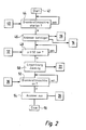
- the electric fuel pump 14 is also switched on. Due to the operation of the electrical Fuel pump 14 and the high pressure fuel pump 18 a certain builds up in the fuel rail 20 Fuel pressure. This is accelerated by that initially from the fuel injectors 22 no fuel is injected into the combustion chambers 24.
- a block 48 checks whether the pressure in the Fuel manifold 20 reaches a pressure of 50 bar or has exceeded this. The corresponding signals receives the control and regulating device 34 from the pressure sensor 32.
- block 52 it is checked whether the starting process of the Internal combustion engine 10 can be completed.
- a criterion for for example, the end of the start process may be that the speed of the internal combustion engines 10 a certain Value reached or exceeded.
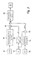
- FIG. 3 shows: Then, in a block 58, a Standard fuel mass mns calculated for the starting process. This fuel mass mns depends on, for example the temperature tmot of the engine 10, which from Temperature sensor 38 is provided. When cold Internal combustion engine 10 needs more fuel overall be injected than with a warm internal combustion engine. at the "standard fuel mass” is that Fuel mass, which at a certain minimum Fuel pressure (3 to 6 bar) would have to be injected.
- the Fuel pressure in the fuel rail 20 during of the starting process of the internal combustion engine 10 is not constant. Since at high pressure in the fuel rail 20 of Fuel from the fuel injections 22 in corresponding combustion chamber 24 is atomized better, so that for a successful ignition of the fuel Less fuel can be injected into the block 60 a weighting factor wf from the pressure pr detected by the pressure sensor 32 in the fuel rail 20 formed.
- the characteristic curve is designed so that when the Pressure pr in the fuel rail 20 is approximately that of of the electric fuel pump 14 generate pressure corresponds (approx. 3-6 bar), the weighting factor wf den Has value 1. At a pressure pr in the fuel rail 20, which is higher than this Minimum pressure, the weighting factor wf becomes less than 1. The weighting factor wf in 62 becomes that in block 58 calculated standard fuel mass multiplied mns.
- the signal from the speed sensor becomes 36 the position of the ZOT of the piston (not shown) of the corresponding combustion chamber 24 determined.
- ZOT means one Angle position before top dead center ignition.
- the Piston position of a combustion chamber 24 can be from the speed sensor 36 are recorded, since it is designed so that it too can detect the angular position of the crankshaft 28.
- Out the position of the piston of a combustion chamber 24 can then also in block 64 the one prevailing in the combustion chamber 24 current pressure pb can be determined.
Landscapes
- Engineering & Computer Science (AREA)
- Chemical & Material Sciences (AREA)
- Combustion & Propulsion (AREA)
- Mechanical Engineering (AREA)
- General Engineering & Computer Science (AREA)
- Electrical Control Of Air Or Fuel Supplied To Internal-Combustion Engine (AREA)
- Combined Controls Of Internal Combustion Engines (AREA)
- Fuel-Injection Apparatus (AREA)
Abstract
Description
- Figur 1
- eine schematische Darstellung einer Brennkraftmaschine mit Benzin-Direkteinspritzung;
- Figur 2
- ein Ablaufdiagramm, welches ein Verfahren zum Starten der Brennkraftmaschine von Figur 1 darstellt;
- Figur 3
- ein Ablaufdiagramm, welches ein erstes Ausführungsbeispiel eines Verfahrens zur Bestimmung der beim Start der Brennkraftmaschine einzuspritzenden Kraftstoffmasse und der Einspritzzeit darstellt; und
- Figur 4
- ein Diagramm ähnlich Figur 3 eines zweiten Ausführungsbeispiels eines Verfahrens zur Bestimmung der beim Start einzuspritzenden Kraftstoffmasse und der Einspritzzeit.
Claims (13)
- Verfahren zum Betreiben einer Brennkraftmaschine (10), bei dem Kraftstoff mittels mindestens einer Kraftstoffpumpe (14, 18) in eine Kraftstoff-Sammelleitung (20) gefördert wird, aus der er über mindestens eine Kraftstoff-Einspritzvorrichtung (22) direkt in mindestens einen Brennraum (24) der Brennkraftmaschine (10) gelangt, dadurch gekennzeichnet, dass die beim Start der Brennkraftmaschine (10) bei einer Einspritzung (50) von der Kraftstoff-Einspritzvorrichtung (22) in den Brennraum (24) einzuspritzende Kraftstoffmasse (ms) vom Druck (pr) in der Kraftstoff-Sammelleitung (20) abhängt.
- Verfahren nach Anspruch 1, dadurch gekennzeichnet, dass die beim Start der Brennkraftmaschine (10) bei einer Einspritzung (50) von der Kraftstoff-Einspritzvorrichtung (22) in den Brennraum (24) einzuspritzende Kraftstoffmasse (ms) dadurch gebildet wird, dass eine Norm-Kraftstoffmasse (mns) bestimmt wird, die beim Start bei einem bestimmten Druck in der Kraftstoff-Sammelleitung (20) in den Brennraum (24) einzuspritzen ist, und diese Norm-Kraftstoffmasse (mns) mit einem Wichtungsfaktor (wf) multipliziert wird (62), der dann, wenn der Druck (pr) in der Kraftstoff-Sammelleitung (20) gleich dem bestimmten Druck ist, den Wert 1 hat, und der bei einer Abweichung des Drucks (pr) in der Kraftstoff-Sammelleitung (20) von dem bestimmten Druck einen Wert ungleich 1 annimmt.
- Verfahren nach Anspruch 1, dadurch gekennzeichnet, dass die beim Start der Brennkraftmaschine (10) bei einer Einspritzung (50) von der Kraftstoff-Einspritzvorrichtung (22) in den Brennraum (24) einzuspritzende Kraftstoffmasse (mns) von der Druckdifferenz (dprpb) zwischen Brennraum (24) und Kraftstoff-Sammelleitung (20) abhängt.
- Verfahren nach Ansperuch 3, dass die beim Start der Brennkraftmaschine (10) bei einer Einspritzung (50) von der Kraftstoff-Einspritzvorrichtung (22) in den Brennraum (24) einzuspritzende Kraftstoffmasse (ms) dadurch gebildet wird, dass eine Norm-Kraftstoffmasse (mns) bestimmt wird, die beim Start bei einer bestimmten Druckdifferenz zwischen Brennraum (24) und Kraftstoff-Sammelleitung (20) in den Brennraum (24) einzuspritzen ist, und diese Norm-Kraftstoffmasse (mns) mit einem Wichtungsfaktor (wf) multipliziert wird, der dann, wenn die Druckdifferenz (dpbpr) zwischen Brennraum (24) und Kraftstoff-Sammelleitung (20) gleich der bestimmten Druckdifferenz ist, den Wert 1 hat, und der bei einer Abweichung der Druckdifferenz (dpbpr) von der bestimmten Druckdifferenz einen Wert ungleich 1 annimmt.
- Verfahren nach einem der Ansprüche 2 oder 4, dadurch gekennzeichnet, dass der Wichtungsfaktor (wf) mittels einer Kennlinie (60) bestimmt wird, die mit dem Druck (pr) in der Kraftstoff-Sammelleitung (20) oder der Druckdifferenz (dpbpr) zwischen Brennraum (24) und Kraftstoff-Sammelleitung (20) adressiert wird.
- Verfahren nach einem der vorhergehenden Ansprüche, dadurch gekennzeichnet, dass die Öffnungsdauer (ti) der Kraftstoff-Einspritzvorrichtung (22) bei einer Einspritzung (50) beim Start der Brennkraftmaschine (10) von der bei einer Einspritzung (50) in den Brennraum (24) einzuspritzenden Kraftstoffmasse (ms) und von der Druckdifferenz (dpbpr) zwischen Brennraum (24) und Kraftstoff-Sammelleitung (20) abhängt.
- Verfahren nach einem der vorhergehenden Ansprüche, dadurch gekennzeichnet, dass nur dann, wenn in der Kraftstoff-Sammelleitung (20) ein Druck (pr) von mindestens 20 bar, insbesondere mindestens ungefähr 50 bar, herrscht, Kraftstoff von der Kraftstoff-Einspritzvorrichtung (22) in den Brennraum (24) der Brennkraftmaschine (10) eingespritzt wird.
- Verfahren nach Anspruch 7, dadurch gekennzeichnet, dass mindestens eine Kraftstoffpumpe (14, 18) wenigstens zum Starten der Brennkraftmaschine (10) wenigstens mittelbar elektrisch angetrieben wird.
- Verfahren nach Anspruch 8, dadurch gekennzeichnet, dass mindestens eine Kraftstoffpumpe (18) mechanisch von der Brennkraftmaschine (10) angetrieben und beim Starten der Brennkraftmaschine (10) ein elektrischer Anlasser (26) betätigt wird (46).
- Computerprogramm, dadurch gekennzeichnet, dass es zur Durchführung des Verfahrens nach einem der vorhergehenden Ansprüche geeignet ist, wenn es auf einem Computer ausgeführt wird.
- Computerprogramm nach Anspruch 10, dadurch gekennzeichnet, dass es auf einem Speicher, insbesondere auf einem Flash-Memory oder einem Ferrit-RAM, abgespeichert ist.
- Steuer- und/oder Regelgerät (34) zum Betreiben einer Brennkraftmaschine (10), dadurch gekennzeichnet, dass es einen Speicher umfasst, auf dem ein Computerprogramm nach einem der Ansprüche 10 oder 11 abgespeichert ist.
- Brennkraftmaschine (10), mit einem Kraftstoffbehälter (12), mit mindestens einer Kraftstoffpumpe (14, 18), welche Kraftstoff aus dem Kraftstoffbehälter (12) in eine Kraftstoff-Sammelleitung (20) fördert, mit mindestens einer Kraftstoff-Einspritzvorrichtung (22), welche an die Kraftstoff-Sammelleitung (20) angeschlossen ist und Kraftstoff direkt in mindestens einen Brennraum (24) der Brennkraftmaschine (10) einspritzt, und mit einem Drucksensor (32), welcher den Druck in der Kraftstoff-Sammelleitung (20) erfasst, dadurch gekennzeichnet, dass sie ein Steuer-und/oder Regelgerät (34) nach Anspruch 11 umfasst.
Applications Claiming Priority (2)
| Application Number | Priority Date | Filing Date | Title |
|---|---|---|---|
| DE2001147815 DE10147815A1 (de) | 2001-09-27 | 2001-09-27 | Verfahren, Computerprogramm und Steuer- und/oder Regelgerät zum Betreiben einer Brennkraftmaschine, sowie Brennkraftmaschine |
| DE10147815 | 2001-09-27 |
Publications (3)
| Publication Number | Publication Date |
|---|---|
| EP1298303A2 true EP1298303A2 (de) | 2003-04-02 |
| EP1298303A3 EP1298303A3 (de) | 2004-12-01 |
| EP1298303B1 EP1298303B1 (de) | 2007-04-11 |
Family
ID=7700588
Family Applications (1)
| Application Number | Title | Priority Date | Filing Date |
|---|---|---|---|
| EP20020018418 Expired - Lifetime EP1298303B1 (de) | 2001-09-27 | 2002-08-16 | Verfahren und Steuer- und/oder Regelgerät zum Betreiben einer Brennkraftmaschine, sowie Brennkraftmaschine |
Country Status (3)
| Country | Link |
|---|---|
| EP (1) | EP1298303B1 (de) |
| JP (1) | JP2003155946A (de) |
| DE (2) | DE10147815A1 (de) |
Cited By (1)
| Publication number | Priority date | Publication date | Assignee | Title |
|---|---|---|---|---|
| WO2006080472A1 (en) * | 2005-01-31 | 2006-08-03 | Toyota Jidosha Kabushiki Kaisha | Control apparatus for internal combustion engine |
Families Citing this family (1)
| Publication number | Priority date | Publication date | Assignee | Title |
|---|---|---|---|---|
| JP2016008553A (ja) | 2014-06-25 | 2016-01-18 | スズキ株式会社 | 燃料噴射制御装置 |
Family Cites Families (9)
| Publication number | Priority date | Publication date | Assignee | Title |
|---|---|---|---|---|
| DE19547644B4 (de) * | 1995-12-20 | 2004-03-11 | Robert Bosch Gmbh | Verfahren und Vorrichtung zur Steuerung der Kraftstoffzumessung in eine Brennkraftmaschine |
| JP3695046B2 (ja) * | 1997-02-07 | 2005-09-14 | いすゞ自動車株式会社 | エンジンの燃料噴射方法及びその装置 |
| DE19726757B4 (de) * | 1997-06-24 | 2005-04-14 | Robert Bosch Gmbh | Verfahren zur Steuerung und/oder Regelung einer mit mehreren Brennräumen versehenen Brennkraftmaschine |
| DE19823280C1 (de) * | 1998-05-25 | 1999-11-11 | Siemens Ag | Verfahren zum Betreiben einer direkteinspritzenden Brennkraftmaschine während des Starts |
| DE19913407A1 (de) * | 1999-03-25 | 2000-09-28 | Bosch Gmbh Robert | Verfahren zum Betreiben einer Brennkraftmaschine |
| DE19937148B4 (de) * | 1999-08-06 | 2012-12-27 | Robert Bosch Gmbh | Verfahren zur Bestimmung der Kraftstoff-Einspritzmengen |
| EP1132613B1 (de) * | 2000-03-09 | 2004-05-19 | Siemens Aktiengesellschaft | Verfahren zum Starten einer Brennkraftmaschine |
| DE10012024A1 (de) * | 2000-03-11 | 2001-09-27 | Bosch Gmbh Robert | Verfahren zum Betreiben einer Brennkraftmaschine |
| DE10053091A1 (de) * | 2000-10-26 | 2002-05-08 | Bosch Gmbh Robert | Verfahren zum Starten einer Brennkraftmaschine |
-
2001
- 2001-09-27 DE DE2001147815 patent/DE10147815A1/de not_active Withdrawn
-
2002
- 2002-08-16 EP EP20020018418 patent/EP1298303B1/de not_active Expired - Lifetime
- 2002-08-16 DE DE50209905T patent/DE50209905D1/de not_active Expired - Lifetime
- 2002-09-27 JP JP2002284348A patent/JP2003155946A/ja active Pending
Cited By (2)
| Publication number | Priority date | Publication date | Assignee | Title |
|---|---|---|---|---|
| WO2006080472A1 (en) * | 2005-01-31 | 2006-08-03 | Toyota Jidosha Kabushiki Kaisha | Control apparatus for internal combustion engine |
| US7814743B2 (en) | 2005-01-31 | 2010-10-19 | Toyota Jidosha Kabushiki Kaisha | Control apparatus for internal combustion engine |
Also Published As
| Publication number | Publication date |
|---|---|
| JP2003155946A (ja) | 2003-05-30 |
| DE10147815A1 (de) | 2003-04-24 |
| DE50209905D1 (de) | 2007-05-24 |
| EP1298303A3 (de) | 2004-12-01 |
| EP1298303B1 (de) | 2007-04-11 |
Similar Documents
| Publication | Publication Date | Title |
|---|---|---|
| DE102012016877B4 (de) | Start-Regel- bzw. Steuervorrichtung für einen Selbstzündungsmotor und korresponierendes Verfahren | |
| DE112014001963B4 (de) | Steuervorrichtung für einen Fremdzündungsmotor | |
| EP1364112B1 (de) | Verfahren, computerprogramm und steuer- und/oder regelgerät zum betreiben einer brennkraftmaschine sowie brennkraftmaschine | |
| EP1485596B1 (de) | Verfahren zum betreiben einer brennkraftmaschine mit mehrfacheinspritzung in der startphase | |
| DE102015119924A1 (de) | Verfahren und Systeme zur Einstellung einer Direkteinspritzdüse | |
| DE60013472T2 (de) | Verfahren zur regelung des starts einer brennkraftmaschine mit direkteinspritzung | |
| DE10254921B4 (de) | Kraftstoffzufuhr- und Einspritzsystem sowie Verfahren zum Steuern desselben | |
| DE10240069A1 (de) | Kraftstoffeinspritzsammelsystem, das das Startvermögen einer Kraftmaschine gewährleistet | |
| EP1495222B1 (de) | Verfahren zum berwachen einer brennkraftmaschine | |
| EP1438495B1 (de) | Verfahren, computerprogramm, steuer- und regelgerät zum betreiben einer brennkraftmaschine, sowie brennkraftmaschine | |
| EP1090221B1 (de) | Verfahren zum betreiben einer brennkraftmaschine insbesondere eines kraftfahrzeugs | |
| WO2013075965A1 (de) | Verfahren und vorrichtung zur steuerung einer brennkraftmaschine | |
| DE102011056159B4 (de) | Brennstoffeinspritzsteuerung für eine Verbrennungskraftmaschine | |
| DE102004002139A1 (de) | Kraftstoffversorgungssystem für eine Brennkraftmaschine | |
| DE102012101010A1 (de) | Anlass-Steuervorrichtung für einen Direkteinspritzungs-Verbrennungsmotor | |
| DE10127516A1 (de) | Verfahren, Computerprogramm und Steuer- und/oder Regelgerät zum Betreiben einer Brennkraftmaschine sowie Kraftstoffsystem für eine Brennkraftmaschine | |
| EP1311750B1 (de) | Verfahren, computerprogramm und steuer-und/oder regeleinrichtung zum betreiben einer brennkraftmaschine | |
| DE69828567T2 (de) | Vorrichtung zur Regelung der Voreinspritzung in einer Brennkraftmaschine | |
| EP1298303B1 (de) | Verfahren und Steuer- und/oder Regelgerät zum Betreiben einer Brennkraftmaschine, sowie Brennkraftmaschine | |
| DE102004046628A1 (de) | Verfahren zum Starten einer Brennkraftmaschine | |
| DE10018050C2 (de) | Verfahren zum Betreiben einer Brennkraftmaschine | |
| EP1436495B1 (de) | Verfahren, computerprogramm und steuer- und/oder regelgerät zum betreiben einer brennkraftmaschine mit direkteinspritzung | |
| DE10038565C2 (de) | Kraftstoffversorgungssystem für eine Brennkraftmaschine insbesondere eines Kraftfahrzeugs | |
| DE102011002475B4 (de) | Kraftstoffeinspritzsteuereinrichtung einer Brennkraftmaschine | |
| EP1199459A2 (de) | Verfahren zum Starten einer Brennkraftmaschine |
Legal Events
| Date | Code | Title | Description |
|---|---|---|---|
| PUAI | Public reference made under article 153(3) epc to a published international application that has entered the european phase |
Free format text: ORIGINAL CODE: 0009012 |
|
| AK | Designated contracting states |
Kind code of ref document: A2 Designated state(s): AT BE BG CH CY CZ DE DK EE ES FI FR GB GR IE IT LI LU MC NL PT SE SK TR |
|
| AX | Request for extension of the european patent |
Extension state: AL LT LV MK RO SI |
|
| PUAL | Search report despatched |
Free format text: ORIGINAL CODE: 0009013 |
|
| AK | Designated contracting states |
Kind code of ref document: A3 Designated state(s): AT BE BG CH CY CZ DE DK EE ES FI FR GB GR IE IT LI LU MC NL PT SE SK TR |
|
| AX | Request for extension of the european patent |
Extension state: AL LT LV MK RO SI |
|
| 17P | Request for examination filed |
Effective date: 20050601 |
|
| AKX | Designation fees paid |
Designated state(s): DE ES FR IT |
|
| GRAP | Despatch of communication of intention to grant a patent |
Free format text: ORIGINAL CODE: EPIDOSNIGR1 |
|
| GRAS | Grant fee paid |
Free format text: ORIGINAL CODE: EPIDOSNIGR3 |
|
| GRAA | (expected) grant |
Free format text: ORIGINAL CODE: 0009210 |
|
| AK | Designated contracting states |
Kind code of ref document: B1 Designated state(s): DE ES FR IT |
|
| REF | Corresponds to: |
Ref document number: 50209905 Country of ref document: DE Date of ref document: 20070524 Kind code of ref document: P |
|
| PG25 | Lapsed in a contracting state [announced via postgrant information from national office to epo] |
Ref country code: ES Free format text: LAPSE BECAUSE OF FAILURE TO SUBMIT A TRANSLATION OF THE DESCRIPTION OR TO PAY THE FEE WITHIN THE PRESCRIBED TIME-LIMIT Effective date: 20070722 |
|
| ET | Fr: translation filed | ||
| PLBE | No opposition filed within time limit |
Free format text: ORIGINAL CODE: 0009261 |
|
| STAA | Information on the status of an ep patent application or granted ep patent |
Free format text: STATUS: NO OPPOSITION FILED WITHIN TIME LIMIT |
|
| 26N | No opposition filed |
Effective date: 20080114 |
|
| PGFP | Annual fee paid to national office [announced via postgrant information from national office to epo] |
Ref country code: FR Payment date: 20090819 Year of fee payment: 8 |
|
| PGFP | Annual fee paid to national office [announced via postgrant information from national office to epo] |
Ref country code: IT Payment date: 20090824 Year of fee payment: 8 |
|
| REG | Reference to a national code |
Ref country code: FR Ref legal event code: ST Effective date: 20110502 |
|
| PG25 | Lapsed in a contracting state [announced via postgrant information from national office to epo] |
Ref country code: IT Free format text: LAPSE BECAUSE OF NON-PAYMENT OF DUE FEES Effective date: 20100816 |
|
| PG25 | Lapsed in a contracting state [announced via postgrant information from national office to epo] |
Ref country code: FR Free format text: LAPSE BECAUSE OF NON-PAYMENT OF DUE FEES Effective date: 20100831 |
|
| PGFP | Annual fee paid to national office [announced via postgrant information from national office to epo] |
Ref country code: DE Payment date: 20131025 Year of fee payment: 12 |
|
| REG | Reference to a national code |
Ref country code: DE Ref legal event code: R119 Ref document number: 50209905 Country of ref document: DE |
|
| REG | Reference to a national code |
Ref country code: DE Ref legal event code: R119 Ref document number: 50209905 Country of ref document: DE Effective date: 20150303 |
|
| PG25 | Lapsed in a contracting state [announced via postgrant information from national office to epo] |
Ref country code: DE Free format text: LAPSE BECAUSE OF NON-PAYMENT OF DUE FEES Effective date: 20150303 |