EP1298292A2 - Controller of compression-ignition engine - Google Patents
Controller of compression-ignition engine Download PDFInfo
- Publication number
- EP1298292A2 EP1298292A2 EP02021788A EP02021788A EP1298292A2 EP 1298292 A2 EP1298292 A2 EP 1298292A2 EP 02021788 A EP02021788 A EP 02021788A EP 02021788 A EP02021788 A EP 02021788A EP 1298292 A2 EP1298292 A2 EP 1298292A2
- Authority
- EP
- European Patent Office
- Prior art keywords
- compression ignition
- combustion
- control system
- air
- fuel ratio
- Prior art date
- Legal status (The legal status is an assumption and is not a legal conclusion. Google has not performed a legal analysis and makes no representation as to the accuracy of the status listed.)
- Withdrawn
Links
Images


Classifications
-
- F—MECHANICAL ENGINEERING; LIGHTING; HEATING; WEAPONS; BLASTING
- F02—COMBUSTION ENGINES; HOT-GAS OR COMBUSTION-PRODUCT ENGINE PLANTS
- F02D—CONTROLLING COMBUSTION ENGINES
- F02D41/00—Electrical control of supply of combustible mixture or its constituents
- F02D41/30—Controlling fuel injection
- F02D41/3011—Controlling fuel injection according to or using specific or several modes of combustion
- F02D41/3064—Controlling fuel injection according to or using specific or several modes of combustion with special control during transition between modes
-
- F—MECHANICAL ENGINEERING; LIGHTING; HEATING; WEAPONS; BLASTING
- F02—COMBUSTION ENGINES; HOT-GAS OR COMBUSTION-PRODUCT ENGINE PLANTS
- F02D—CONTROLLING COMBUSTION ENGINES
- F02D43/00—Conjoint electrical control of two or more functions, e.g. ignition, fuel-air mixture, recirculation, supercharging or exhaust-gas treatment
-
- F—MECHANICAL ENGINEERING; LIGHTING; HEATING; WEAPONS; BLASTING
- F02—COMBUSTION ENGINES; HOT-GAS OR COMBUSTION-PRODUCT ENGINE PLANTS
- F02B—INTERNAL-COMBUSTION PISTON ENGINES; COMBUSTION ENGINES IN GENERAL
- F02B1/00—Engines characterised by fuel-air mixture compression
- F02B1/12—Engines characterised by fuel-air mixture compression with compression ignition
-
- F—MECHANICAL ENGINEERING; LIGHTING; HEATING; WEAPONS; BLASTING
- F02—COMBUSTION ENGINES; HOT-GAS OR COMBUSTION-PRODUCT ENGINE PLANTS
- F02D—CONTROLLING COMBUSTION ENGINES
- F02D41/00—Electrical control of supply of combustible mixture or its constituents
- F02D41/0025—Controlling engines characterised by use of non-liquid fuels, pluralities of fuels, or non-fuel substances added to the combustible mixtures
- F02D41/0047—Controlling exhaust gas recirculation [EGR]
- F02D41/005—Controlling exhaust gas recirculation [EGR] according to engine operating conditions
- F02D41/0057—Specific combustion modes
-
- F—MECHANICAL ENGINEERING; LIGHTING; HEATING; WEAPONS; BLASTING
- F02—COMBUSTION ENGINES; HOT-GAS OR COMBUSTION-PRODUCT ENGINE PLANTS
- F02D—CONTROLLING COMBUSTION ENGINES
- F02D41/00—Electrical control of supply of combustible mixture or its constituents
- F02D41/02—Circuit arrangements for generating control signals
- F02D41/021—Introducing corrections for particular conditions exterior to the engine
- F02D41/0235—Introducing corrections for particular conditions exterior to the engine in relation with the state of the exhaust gas treating apparatus
- F02D41/0295—Control according to the amount of oxygen that is stored on the exhaust gas treating apparatus
-
- F—MECHANICAL ENGINEERING; LIGHTING; HEATING; WEAPONS; BLASTING
- F02—COMBUSTION ENGINES; HOT-GAS OR COMBUSTION-PRODUCT ENGINE PLANTS
- F02D—CONTROLLING COMBUSTION ENGINES
- F02D41/00—Electrical control of supply of combustible mixture or its constituents
- F02D41/02—Circuit arrangements for generating control signals
- F02D41/14—Introducing closed-loop corrections
- F02D41/1438—Introducing closed-loop corrections using means for determining characteristics of the combustion gases; Sensors therefor
- F02D41/1439—Introducing closed-loop corrections using means for determining characteristics of the combustion gases; Sensors therefor characterised by the position of the sensor
- F02D41/1441—Plural sensors
-
- F—MECHANICAL ENGINEERING; LIGHTING; HEATING; WEAPONS; BLASTING
- F02—COMBUSTION ENGINES; HOT-GAS OR COMBUSTION-PRODUCT ENGINE PLANTS
- F02D—CONTROLLING COMBUSTION ENGINES
- F02D41/00—Electrical control of supply of combustible mixture or its constituents
- F02D41/02—Circuit arrangements for generating control signals
- F02D41/14—Introducing closed-loop corrections
- F02D41/1438—Introducing closed-loop corrections using means for determining characteristics of the combustion gases; Sensors therefor
- F02D41/1444—Introducing closed-loop corrections using means for determining characteristics of the combustion gases; Sensors therefor characterised by the characteristics of the combustion gases
- F02D41/146—Introducing closed-loop corrections using means for determining characteristics of the combustion gases; Sensors therefor characterised by the characteristics of the combustion gases the characteristics being an NOx content or concentration
- F02D41/1463—Introducing closed-loop corrections using means for determining characteristics of the combustion gases; Sensors therefor characterised by the characteristics of the combustion gases the characteristics being an NOx content or concentration of the exhaust gases downstream of exhaust gas treatment apparatus
- F02D41/1465—Introducing closed-loop corrections using means for determining characteristics of the combustion gases; Sensors therefor characterised by the characteristics of the combustion gases the characteristics being an NOx content or concentration of the exhaust gases downstream of exhaust gas treatment apparatus with determination means using an estimation
-
- F—MECHANICAL ENGINEERING; LIGHTING; HEATING; WEAPONS; BLASTING
- F02—COMBUSTION ENGINES; HOT-GAS OR COMBUSTION-PRODUCT ENGINE PLANTS
- F02D—CONTROLLING COMBUSTION ENGINES
- F02D41/00—Electrical control of supply of combustible mixture or its constituents
- F02D41/22—Safety or indicating devices for abnormal conditions
- F02D41/222—Safety or indicating devices for abnormal conditions relating to the failure of sensors or parameter detection devices
-
- F—MECHANICAL ENGINEERING; LIGHTING; HEATING; WEAPONS; BLASTING
- F02—COMBUSTION ENGINES; HOT-GAS OR COMBUSTION-PRODUCT ENGINE PLANTS
- F02D—CONTROLLING COMBUSTION ENGINES
- F02D41/00—Electrical control of supply of combustible mixture or its constituents
- F02D41/24—Electrical control of supply of combustible mixture or its constituents characterised by the use of digital means
- F02D41/2406—Electrical control of supply of combustible mixture or its constituents characterised by the use of digital means using essentially read only memories
- F02D41/2425—Particular ways of programming the data
- F02D41/2429—Methods of calibrating or learning
- F02D41/2441—Methods of calibrating or learning characterised by the learning conditions
-
- F—MECHANICAL ENGINEERING; LIGHTING; HEATING; WEAPONS; BLASTING
- F02—COMBUSTION ENGINES; HOT-GAS OR COMBUSTION-PRODUCT ENGINE PLANTS
- F02D—CONTROLLING COMBUSTION ENGINES
- F02D41/00—Electrical control of supply of combustible mixture or its constituents
- F02D41/24—Electrical control of supply of combustible mixture or its constituents characterised by the use of digital means
- F02D41/2406—Electrical control of supply of combustible mixture or its constituents characterised by the use of digital means using essentially read only memories
- F02D41/2425—Particular ways of programming the data
- F02D41/2429—Methods of calibrating or learning
- F02D41/2451—Methods of calibrating or learning characterised by what is learned or calibrated
- F02D41/2454—Learning of the air-fuel ratio control
-
- F—MECHANICAL ENGINEERING; LIGHTING; HEATING; WEAPONS; BLASTING
- F02—COMBUSTION ENGINES; HOT-GAS OR COMBUSTION-PRODUCT ENGINE PLANTS
- F02D—CONTROLLING COMBUSTION ENGINES
- F02D41/00—Electrical control of supply of combustible mixture or its constituents
- F02D41/30—Controlling fuel injection
- F02D41/3011—Controlling fuel injection according to or using specific or several modes of combustion
- F02D41/3017—Controlling fuel injection according to or using specific or several modes of combustion characterised by the mode(s) being used
- F02D41/3035—Controlling fuel injection according to or using specific or several modes of combustion characterised by the mode(s) being used a mode being the premixed charge compression-ignition mode
-
- F—MECHANICAL ENGINEERING; LIGHTING; HEATING; WEAPONS; BLASTING
- F02—COMBUSTION ENGINES; HOT-GAS OR COMBUSTION-PRODUCT ENGINE PLANTS
- F02D—CONTROLLING COMBUSTION ENGINES
- F02D41/00—Electrical control of supply of combustible mixture or its constituents
- F02D41/0002—Controlling intake air
- F02D2041/0017—Controlling intake air by simultaneous control of throttle and exhaust gas recirculation
-
- F—MECHANICAL ENGINEERING; LIGHTING; HEATING; WEAPONS; BLASTING
- F02—COMBUSTION ENGINES; HOT-GAS OR COMBUSTION-PRODUCT ENGINE PLANTS
- F02D—CONTROLLING COMBUSTION ENGINES
- F02D41/00—Electrical control of supply of combustible mixture or its constituents
- F02D41/0025—Controlling engines characterised by use of non-liquid fuels, pluralities of fuels, or non-fuel substances added to the combustible mixtures
- F02D41/0047—Controlling exhaust gas recirculation [EGR]
- F02D41/006—Controlling exhaust gas recirculation [EGR] using internal EGR
-
- F—MECHANICAL ENGINEERING; LIGHTING; HEATING; WEAPONS; BLASTING
- F02—COMBUSTION ENGINES; HOT-GAS OR COMBUSTION-PRODUCT ENGINE PLANTS
- F02D—CONTROLLING COMBUSTION ENGINES
- F02D41/00—Electrical control of supply of combustible mixture or its constituents
- F02D41/008—Controlling each cylinder individually
- F02D41/0087—Selective cylinder activation, i.e. partial cylinder operation
-
- F—MECHANICAL ENGINEERING; LIGHTING; HEATING; WEAPONS; BLASTING
- F02—COMBUSTION ENGINES; HOT-GAS OR COMBUSTION-PRODUCT ENGINE PLANTS
- F02D—CONTROLLING COMBUSTION ENGINES
- F02D41/00—Electrical control of supply of combustible mixture or its constituents
- F02D41/02—Circuit arrangements for generating control signals
- F02D41/14—Introducing closed-loop corrections
- F02D41/1401—Introducing closed-loop corrections characterised by the control or regulation method
- F02D41/1402—Adaptive control
-
- F—MECHANICAL ENGINEERING; LIGHTING; HEATING; WEAPONS; BLASTING
- F02—COMBUSTION ENGINES; HOT-GAS OR COMBUSTION-PRODUCT ENGINE PLANTS
- F02D—CONTROLLING COMBUSTION ENGINES
- F02D41/00—Electrical control of supply of combustible mixture or its constituents
- F02D41/02—Circuit arrangements for generating control signals
- F02D41/14—Introducing closed-loop corrections
- F02D41/1438—Introducing closed-loop corrections using means for determining characteristics of the combustion gases; Sensors therefor
- F02D41/1444—Introducing closed-loop corrections using means for determining characteristics of the combustion gases; Sensors therefor characterised by the characteristics of the combustion gases
- F02D41/1454—Introducing closed-loop corrections using means for determining characteristics of the combustion gases; Sensors therefor characterised by the characteristics of the combustion gases the characteristics being an oxygen content or concentration or the air-fuel ratio
-
- F—MECHANICAL ENGINEERING; LIGHTING; HEATING; WEAPONS; BLASTING
- F02—COMBUSTION ENGINES; HOT-GAS OR COMBUSTION-PRODUCT ENGINE PLANTS
- F02D—CONTROLLING COMBUSTION ENGINES
- F02D41/00—Electrical control of supply of combustible mixture or its constituents
- F02D41/30—Controlling fuel injection
- F02D41/38—Controlling fuel injection of the high pressure type
- F02D41/40—Controlling fuel injection of the high pressure type with means for controlling injection timing or duration
- F02D41/402—Multiple injections
-
- Y—GENERAL TAGGING OF NEW TECHNOLOGICAL DEVELOPMENTS; GENERAL TAGGING OF CROSS-SECTIONAL TECHNOLOGIES SPANNING OVER SEVERAL SECTIONS OF THE IPC; TECHNICAL SUBJECTS COVERED BY FORMER USPC CROSS-REFERENCE ART COLLECTIONS [XRACs] AND DIGESTS
- Y02—TECHNOLOGIES OR APPLICATIONS FOR MITIGATION OR ADAPTATION AGAINST CLIMATE CHANGE
- Y02T—CLIMATE CHANGE MITIGATION TECHNOLOGIES RELATED TO TRANSPORTATION
- Y02T10/00—Road transport of goods or passengers
- Y02T10/10—Internal combustion engine [ICE] based vehicles
- Y02T10/40—Engine management systems
Definitions
- the present invention relates to a controller or control system of a compression ignition engine. Particularly, the present invention relates to the controller of the compression ignition engine for preventing any deterioration in exhaust gas purification at a transition between spark ignition operation and compression ignition operation and during the compression ignition.
- the conventional lean-burn engines can improve fuel economy as the result of the effect of pumping loss decrease, and the like.
- Abnormal combustion is prevented by switching the combustion when a difference between the detected ignition timing and the spark ignition timing of a sparking plug becomes lower than a predetermined value.
- NO x under exhaust is detected, and the combustion is switched based on the change in the density of NO x .
- This technology prevents the combustion from becoming unstable (as proposed technology, see Japanese Patent Application Laid-Open No. Hei 11-336600). At this time, the deterioration in exhaust gas purification due to the miss-firing can be prevented by appropriately judging the timing of the switching.
- the catalyst which purifies the exhaust is not considered even though the conventional technology can prevent the deterioration in exhaust gas purification due to the abnormal combustion possibly caused in transition between the compression ignition and the spark ignition. Therefore, even in the state that the exhaust cannot be purified with the catalyst, the switching for the combustion is carried out, and it occurs a possibility to deprave the exhaust discharged in atmosphere. Namely, if the air/fuel ratio becomes excessively lean condition at the time of switching when the three way catalyst is provided in an exhaust pipe, NO x is exhausted as it is without being purified. On the contrary, if the air/fuel ratio becomes excessively rich condition, HC and CO are exhausted without being purified.
- the inventors of the present invention have found that it is possible to monitor the fact that the exhaust gas is purified with the catalyst at the switching transition between the spark ignition mode operation and the compression ignition mode operation by using a three way catalyst and an NO x detector located at the downstream side of the three way catalyst, and it is possible to monitor the fact that the combustion aggravates also at the time of the compression ignition mode operation. They found that on the basis of this knowledge a system which achieves this can be provided with a minimum system structure. The above-mentioned prior art techniques do not have at all special consideration about this.
- One object of the present invention is to provide a control system for a compression injection engine which can prevent deterioration in exhaust purification at the time of the switching of combustion between spark ignition and compression ignition, at the time of the spark ignition combustion and the compression injection combustion, and can diagnose any deterioration of an NO x detector and a three way catalyst.
- a control system for a compression ignition engine can comprise:
- the control system for the compression ignition engine according to the present invention constructed as set forth above, can be provided with the NO x detector located downstream side of the catalytic converter. Since engine control is performed on the basis of the No x detection value, a minimum system of the compression ignition engine can be constructed. Furthermore, with the construction set forth above, prevention of deterioration of exhaust gas purification performance can be achieved upon switching of combustion mode between spark ignition and compression ignition in addition to combustion in the spark ignition mode and compression ignition mode, and prevention of deterioration of exhaust gas purification performance by diagnosis of the No x sensor, the catalytic converter and so forth.
- control system of the compression ignition engine may use an output signal of the NO x detector for preventing deterioration of exhaust gas purification performance.
- control system may prevent deterioration of exhaust gas purification performance upon switching transition of combustion mode between spark ignition and compression ignition, during spark ignition mode combustion and during compression ignition mode combustion.
- control system may further comprise:
- control system can perform fuel injection between an expansion stroke and an exhaust stroke in the compression ignition mode combustion.
- the control system may comprise:
- control system may comprise fuel cut-off means for interrupting fuel injection during deceleration, and fatigue of NO x detector may be detected on the basis of the output signal of the NO x detector during fuel cut-off.
- the control system may comprise fuel recovery means for recovering fuel injection after fuel cut-off, abnormality of the NO x detector may be judged when a difference the NO x detection value during fuel recovery and the NO x detection value during fuel cut-off is less than or equal to a predetermined value.
- the control system may further comprise air/fuel ratio control means for controlling air/fuel ratio so that an output of the air/fuel ratio detector becomes close to a target air/fuel ratio, for diagnosis of fatigue of the catalytic converter on the basis of the output signal of the NO x detector when the target air/fuel ratio is set at stoichiometric value.
- an automotive vehicle may have a control system for a compression ignition engine constructed as set forth above.
- FIG. 3 shows the embodiment of the present invention, in which is illustrated a system construction applied the preferred embodiment of a control system for a compression ignition engine.
- An engine 50 is a compression ignition engine which compresses a premixed air/fuel mixture for self-ignition.
- An air-flow sensor 1 measuring an intake air flow rate and a throttle valve 2 adjusting intake air flow rate are provided at appropriate positions within an air induction passage 11, respectively.
- injectors 3 for injecting fuel into the air induction passage or combustion chambers, spark ignition plugs 4 supplying ignition energy and variable valves 5 controlling EGR amount to be recirculated into the combustion chambers, respectively, are provided for respective engine cylinders 12.
- a three-way catalytic converter 7 for purifying an exhaust gas, an air/fuel ratio sensor 6, such as O 2 sensor as one embodiment of an air/fuel ratio detector, for detecting an air/fuel ratio from the exhaust gas at upstream side of the catalytic converter 7, an NO x sensor 8 detecting NO x concentration at downstream side of the catalytic converter 7 are provided in an exhaust passage. Furthermore, on a crankshaft 14, a crank angle sensor 9 for detecting or deriving a crank shaft angular position is provided. Signals from the air flow sensor 1, the air/fuel ratio sensor 6, the NO x sensor 8 and the crank angle sensor 9 are input to an engine control unit (hereinafter referred to as ECU) 10, in which a microcomputer is provided for signal processing.
- ECU engine control unit
- ECU 10 includes an exhaust control unit 10A performing various control on the basis of an output signal of the NO x sensor 8 for preventing deterioration of exhaust gas purification performance, which will be discussed later, and a diagnosis unit 10B.
- the exhaust control unit 10A prevents deterioration in exhaust gas purification performance at the transition in combustion modes between spark ignition and compression ignition, during combustion in spark ignition and during combustion in compression ignition.
- the diagnosis unit 10B prevents deterioration of exhaust gas purification performance through diagnosis of fatigue of NO x sensor 8 and the catalytic converter 7.
- Fig. 4 illustrates relationship between a pressure within the combustion chamber, a fuel injection signal and a spark ignition timing in spark ignition mode operation under control by ECU 10.
- the fuel is injected through the fuel injector 3 in an induction stroke, and the fuel in the combustion chamber is ignited by the spark plug 4 in a compression stroke.
- Fig. 5 illustrates a pressure within the combustion chamber, a fuel injection signal and so forth in compression ignition mode operation under control by ECU 10.
- profiles of an intake valve 5 and an exhaust valve 5 are varied to enclose the exhaust gas (internal EGR) in exhaust stroke.
- an auxiliary fuel is injected by the fuel injector 3 for compression to generate a radical.
- a primary fuel is injected through the fuel injector 3 to cause self-ignition in the fuel.
- ECU 10 controls internal temperature within the cylinder 12 by internal EGR and can also control an ignition temperature by the auxiliary fuel injection and the primary fuel injection for appropriately controlling compression ignition timing.
- Figs. 6(a) and 6(b) show profiles of the intake and exhaust valves 5 for controlling the internal EGR.
- Fig. 6(a) shows a method for increasing the internal EGR by enclosing the exhaust gas by reducing a magnitude of valve lift of the intake and exhaust valves 5 during compression ignition mode operation.
- Fig. 6(b) shows a method for increasing the internal EGR by enclosing the exhaust gas by setting the lifting period of the exhaust valve 5 shorter than the lifting period of the intake valve during the compression ignition mode operation.
- the shown embodiment of the engine 50 is designed for reducing exhaust gas to be discharged to the atmosphere by controlling air/fuel ratio toward stoichometric value during spark ignition mode operation, and for reducing exhaust gas to be discharge to the atmosphere by controlling air/fuel ratio toward stoichiometric value or lean during compression ignition mode operation.
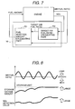
- Fig. 7 is a control block diagram of an air/fuel ratio control system by the exhaust control unit 10A in ECU 10.
- ECU 10 includes a fuel injection calculating portion 701 and a target air/fuel ratio calculating portion 702.
- the target air/fuel ratio calculating portion 702 derives a target air/fuel ratio for optimizing purification efficiency in the catalytic converter 7 on the basis of the detection value of NO x from the NO x sensor 8 to output to the fuel injection calculating portion 701 as one embodiment of the air/fuel ratio control means.
- the fuel injection calculating portion 701 derives a fuel amount to control an actual fuel injection amount detected by the air/fuel ratio sensor 6 toward the target air/fuel ratio to output to the fuel injector 3, and thus controls oxygen storage amount in the catalytic converter 7.
- Fig. 8 shows oxygen storage amount and NO x detection amount when the detected value of the air/fuel ratio sensor 6 indicates lean mixture condition. As shown, when the air/fuel ratio is lean and if the oxygen storage amount reaches a storage limit, purification of NO x by the catalytic converter becomes impossible. Therefore, detection value of NO x is increased.
- the exhaust control unit 10A varies the target air/fuel ratio for feedback control of air/fuel ratio ( ⁇ -control) toward rich side temporarily, and subsequently returns the target air/fuel ratio to the normal target air/fuel ratio for controlling the oxygen storage amount.
- ⁇ -control air/fuel ratio
- some NO x sensors have capability of measurement of oxygen concentration simultaneously with NO x amount.
- feedback control of the air/fuel ratio is performed by setting the target air/fuel ratio so that oxygen concentration on downstream side of the catalytic converter becomes constant. If NO x is detected, the target value of the oxygen concentration is shifted toward rich side until the detection value of NO x sensor 8 becomes zero. Even in this manner, the oxygen storage amount can be controlled appropriately.
- ECU 10 corrects fuel injection amount to control the air/fuel ratio toward the target air/fuel ratio.
- the exhaust control unit 10A reduces the exhaust gas on the basis of the NO x sensor 8 in the following manner when abnormality of the air/fuel sensor 6 is detected.
- Fig. 10 shows a relationship between the NO x detection value and the fuel correction amount by the exhaust control unit 10A of ECU 10 upon failure of the air/fuel sensor.
- the exhaust control unit 10A includes an air/fuel ratio sensor diagnosing means for detecting abnormality of the air/fuel ratio sensor 6. As shown, upon diagnosis of abnormality of the air/fuel ratio sensor 6, the fuel injection amount is corrected on the basis of the output signal of the NO x sensor 8. Namely, when the detection value of NO x is less than or equal to the predetermined value NO x HLe, fuel correction amount is reduced by a given rate. On the other hand, when the NO x detection value exceeds the predetermined value NO x HLe, fuel correction is performed by a given amount toward rich side, and subsequently, the fuel correction amount is increased at a given rate. By this, while the air/fuel ratio becomes slightly lean, excessive offset of the air/fuel ratio may not be caused to prevent deterioration of exhaust gas purification performance.
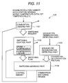
- Fig. 11 is a block diagram showing a control system for preventing deterioration of the exhaust gas purification performance upon switching of combustion mode by the exhaust control unit 10A.
- the exhaust control unit 10A includes a combustion judgment portion 1101, a switching control portion 1102, an exhaust deterioration detecting portion 1103 and a switching learning portion 1104.
- the combustion judgment portion 1101 reads out an engine revolution speed or engine speed, an engine load, such as air intake flow rate, an accelerator depression magnitude, an engine coolant temperature, a catalyst temperature and so on and makes judgment whether switching of the combustion mode is to be performed or not for outputting a switching demand to the switching control portion 1102 on the basis of the result of judgment.
- the combustion judgment portion 1101 is set a map defining a range, in which compression ignition is possible, in relation to the engine revolution speed and the engine load.
- the range capable of combustion ignition will be hereinafter referred to as "combustion ignition range”.
- the combustion judgment portion 1101 derives a target engine load on the basis of the accelerator depression amount.
- the combustion judgment portion 1101 makes judgment whether switching from the spark ignition mode to compression ignition mode is to be performed or not. It should be noted that, in order to prevent deterioration in exhaust gas purification performance, switching of the combustion mode from the spark ignition mode to the compression ignition mode is inhibited when the coolant temperature or the catalyst temperature does not reach a predetermined criterion value even when the engine revolution speed and the engine load falls within the compression ignition range.
- the switching control portion 1102 switches the combustion mode from the spark ignition mode to the compression ignition mode or from the compression ignition mode to the spark ignition mode in accordance with the switching demand, and outputs to the switching learning portion 1104.
- the exhaust deterioration detecting portion 1103 is means for predicting an exhaust deterioration factor on the basis of the detection value of the NO x sensor 8 upon switching. The result of prediction is output to the switching learning portion 1104.
- the switching learning portion 1104 learns control amounts (e.g. spark ignition timing, a throttle control amount, a fuel injection amount, a fuel cut period before switching to the compression ignition, a target air intake amount or a target EGR amount and so on) of the switching control portion 1102.
- control amounts e.g. spark ignition timing, a throttle control amount, a fuel injection amount, a fuel cut period before switching to the compression ignition, a target air intake amount or a target EGR amount and so on
- leaning control objects e.g. combustion mode switching region for switching between the spark ignition mode combustion and the compression ignition mode combustion as judged by the combustion judgment portion 1101
- the intake air flow rate is adjusted to ensure avoidance of rich mixture in relation to the internal EGR amount by learning. Also, since the internal EGR amount can be controlled for enabling switching to the compression ignition mode combustion, deterioration of exhaust gas purification performance can be successfully prevented.
- Fig. 12 shows one example of switching control in combustion mode switching transition from the spark ignition mode combustion to the compression ignition mode combustion by the switching control portion 1102 of the exhaust control unit 10A, which is switching control in steady state (output being constant).
- Respective target values of an operation magnitude of the throttle valve, a lifting magnitude of the exhaust gas 5, a timing of a spark signal of the spark plug 4 and a fuel injection pulse width of the fuel injector 3 are shown in time sequence (toward upward in the drawing, increasing of open angle of the throttle valve, increasing of lifting magnitude, advancing of spark ignition timing, increasing of the fuel injection pulse width).
- a relationship between the internal EGR amount and the exhaust valve lifting magnitude EV1 or a lifting period of the exhaust valve 5 is variable depending upon operating condition, such as the engine revolution speed, the engine load and so forth.
- operating condition such as the engine revolution speed, the engine load and so forth.
- relationship between the internal EGR amount and the exhaust valve lifting magnitude EV1 or the lifting period per operating condition has to be preliminarily derived and set in a form of map or model.
- the exhaust control unit 10A prevents formation of rich air/fuel mixture by preliminarily opening the throttle valve 2 depending upon the internal EGR amount.
- the throttle valve 2 is driven to increase open angle by TV1. Since the internal EGR amount is variable per engine driving range or operation range.
- the throttle opening magnitude TV1 is preliminarily derived by experiments or simulation so that the air/fuel ratio is may not become rich as a feed-forward control amount read out from the map per operation range.
- the engine cylinder 12 in expansion stroke is detected to shift the valve lifting magnitude of the exhaust valve 5 to the predetermined value before entering into the exhaust stroke to control the internal EGR to establish a condition permitting compression ignition mode combustion.
- the spark ignition timing of the relevant cylinder in compression ignition is retarded from a timing of self-ignition of the pre-mixture to switch the combustion mode from the spark ignition mode to the compression ignition.
- the target value of the air/fuel ratio is set to lean. More particularly, the throttle valve 2 is further opened to increase the intake air flow rate, and the fuel injection amount is reduced anticipating improvement of pumping loss component and improvement of combustion efficiency. At this time, it is desirable to develop a maximum torque by controlling compression ignition timing.
- Fig. 13 shows the intake air flow rate, the air/fuel ratio in the exhaust gas discharged from the engine, NO x concentration upstream and downstream of the catalytic converter 7 in time sequence when the shown embodiment of control is executed by the exhaust control unit 10A (in the drawings, toward upward in the drawing, increasing of the intake air flow rate, lean of air/fuel ratio and increasing of NO x concentration are indicated).
- the intake air flow rate becomes constant during spark ignition mode combustion.
- the throttle valve 2 is opened to increase the intake air flow rate.
- the air/fuel ratio detected by the air/flow rate sensor 6 becomes stoichiometric value during the spark ignition mode operation and lean during the compression ignition mode operation.
- NO x amount upstream of the catalytic converter 7 is reduced upon switching transition from the spark ignition mode to the compression ignition mode and thus is lowered to the same level as that during compression ignition mode operation after switching transition to the compression ignition mode. Therefore, NO x amount downstream of the catalytic converter 7 can be maintained at the equal level before and after switching transition.
- the exhaust control by the exhaust control unit 10A is performed by opening the throttle valve 2 in the magnitude of TV1 in order to preventing the air/fuel ratio in the engine cylinder 12 from becoming rich.
- the lifting magnitude of the exhaust valve 5 is reduced in the magnitude of EV1.
- the exhaust control unit 10A is provided with the exhaust deterioration detecting portion 1103 as shown in Fig. 11.
- the exhaust deterioration factor is analyzed by detecting NO x at switching transition to output result of analysis to the switching learning portion 1104.
- the exhaust deterioration detecting portion 1103 makes judgment whether discharging of NO x is caused due to offset in the intake air flow rate control or offset in the EGR control on the basis of the relationship between timing of occurrence of the NO x spike, combustion mode switching timing and output of the air/fuel ratio sensor upstream of the catalytic . converter. Then, in the switching learning portion 1104, feed-forward control is performed so that when the NO x spike is detected before switching of combustion mode, the throttle valve open angle TV1 is reduced depending upon magnitude of the NO x spike. On the other hand, when the NO x spike is detected after switching of the combustion mode, the lifting magnitude EV1 of the exhaust valve 5 is increase depending upon magnitude of the NO x spike.
- the switching learning portion 1104 makes judgment the switching of the combustion mode is not possible when the value after learning exceeds a predetermined control range to update a combustion mode switching range map provided in the combustion judgment portion 1101 to inhibit switching.
- the combustion mode switching range map may be the same map as shown in Fig. 2, or, in the alternative, may be other map in a sense that can implement combustion mode switching control without causing deterioration of exhaust purification performance.
- Figs. 16 to 19 are flowcharts showing operation of the exhaust control by the exhaust control unit 10A.
- Fig. 16 illustrates the control block of Fig. 11 in a form of flowchart.
- step 1601 operating condition (the engine revolution speed, the accelerator depression magnitude, the coolant temperature, the catalyst temperature and so forth) is read out from various sensors. At step 1602, judgment is made whether the combustion mode is to be switched or not in the combustion judgment portion 1101. Then, process is advanced to step 1603.
- operating condition the engine revolution speed, the accelerator depression magnitude, the coolant temperature, the catalyst temperature and so forth
- step 1603 judgment is made whether combustion mode switching demand is present or not. If the combustion mode switching demand is present, namely the answer is YES at step 1603, the process is advanced to step 1604. Then, combustion mode is switched at the switching control portion 1102. The process is then advanced to step 1605. It should be noted that when the combustion mode switching demand is not present as checked at step 1603, a sequence of operation is terminated.
- step 1605 judgment is made whether the switching of the combustion mode is completed or not.
- the process is not advanced to step 1606 until combustion mode switching control is completed.
- the process is advanced to step 1606 to learn the control amount of the switching control portion 1102 or the combustion mode switching range in the combustion judgment portion 1101 on the basis of the detection value of the NO x sensor 8, and then to terminate the sequence of operation.
- Fig. 17 is a flowchart showing the operation of the combustion judgment portion 1101 of the exhaust control unit 10A.
- a switching demand flag is cleared.
- step 1703 check is performed whether switching from the spark ignition mode to the compression ignition mode is possible or not. More particularly, at step 1703, check is performed whether a stable compression ignition mode combustion control is possible or not by checking if the engine revolution speed is lower than or equal to a predetermined value, if the intake air flow rate is smaller than or equal to a predetermined value, if a variation amount of the accelerator depression magnitude falls within a predetermined range, if fluctuation of the engine revolution speed is smaller than or equal to a predetermined value and other conditions. If switching of the control mode is possible, the process is advanced to step 1704. At step 1704, check is performed whether the engine operating condition falls within the operation range permitting switching from the spark ignition mode to the compression ignition mode.
- the range where deterioration of exhaust gas purification performance is not caused at switching transition from the spark ignition mode to the compression ignition mode is defined in a form of a map with respect to the engine revolution speed and an engine output torque, for example, and the current operation range is checked if falls within the thus defined range.
- the process is advanced to step 1705. If stable compression ignition mode combustion control is not possible as checked at step 1703, or, in the alternative, the current operation range does not fall within the range not causing deterioration of exhaust gas purification performance, the sequence of operation is terminated.
- a switching demand flag indicative of the switching demand from the spark ignition mode to the compression ignition mode is set ON. Then, the sequence of operation is terminated.
- step 1702 when the current combustion mode is the compression ignition mode, the process is advanced to step 1706 to check whether a compression ignition permitting condition is not satisfied or not. If the compression ignition permitting condition is not satisfied, the process is advanced to step 1708. On the other hand, if the compression ignition permitting condition is satisfied, the process is advanced to step 1707 to check whether deterioration of combustion is caused or not. At this step, checking of misfiring is performed on the basis of the signal of the crank angle sensor 9 or other, and checking of abnormal combustion is performed on the basis of the signal of the NO x sensor 8.
- step 1707 When deterioration of combustion is detected, namely the answer is YES as checked at step 1707, the process is advanced to step 1708 to set ON the switching demand flag for switching from the compression ignition to the spark ignition. Then, a sequence of operation is terminated. It should be noted that when deterioration of combustion is not detected, a sequence of operation is terminated.
- the combustion judgment portion 1101 of the exhaust control unit 10A issues the switching demand only in a range where switching can be performed without causing deterioration of the exhaust gas purification performance in addition to judgment whether compression ignition mode combustion is possible.
- deterioration of the exhaust gas purification performance during switching transition of the combustion mode can be successfully prevented.
- Fig. 18 is a operational flowchart of one embodiment upon switching from the spark ignition mode to the compression ignition in the switching control portion 1102 of the exhaust control unit 10A.
- the target EGR amount is calculated for switching to the compression ignition mode combustion.
- the target intake air flow rate is set for preventing the mixture in the combustion chamber rich depending upon the target EGR amount.
- the target throttle open angle TV1 for the throttle valve 2 and the target lifting magnitude EV1 of the exhaust valve 5 are set.
- step 1803 the engine cylinder 12, at which switching of combustion mode is initiated, is set.
- step 1804 the open angle of the throttle valve 2 will is increased in the extent of TV1.
- step 1805 the processes is held waiting until the engine cylinder set for initiation of switching enters into the expansion stroke.
- the process is advanced to step 1806 to reduce the lifting magnitude of the exhaust valve 5 by EV1.
- entry into compression stroke in the relevant engine cylinder 12 is waited.
- the spark ignition timing is retarded from the compression ignition timing. Then, a sequence of operation is terminated.
- the switching control portion 1102 of the exhaust control unit 10A calculates an appropriate internal EGR per operation range to set the lifting magnitude of the exhaust valve 5 for assuring transition to the compression ignition mode. Furthermore, by setting the target intake air flow rate depending upon the internal EGR amount to preliminarily open the throttle valve to prevent the air/fuel ratio from becoming rich to cause deterioration of the exhaust gas purification performance.
- Fig. 19 is a operational flowchart of the switching learning portion 1104 of the exhaust control unit 10A.
- step 1901 judgment is made whether deterioration of the exhaust gas purification performance is caused during the spark ignition mode operation or not. If deterioration of the exhaust gas purification performance is caused, namely the answer at step 1901 is YES, the process is advanced to step 1902. On the other hand, if deterioration of the exhaust gas purification performance is not caused, the process is advanced to step 1903.
- step 1902 learning is performed for reducing the target intake air flow rate. Namely, a factor for causing deterioration of the exhaust gas purification performance during spark ignition mode operation is excessively lean air/fuel mixture. Therefore, the target intake air flow rate is adjusted to be smaller. More particularly, by reducing the open angle EV1 of the throttle valve 2, deterioration of the exhaust gas purification performance can be avoided.
- step 1903 judgment is made whether deterioration of the exhaust gas purification performance in the compression ignition mode operation is caused or not. If deterioration of the exhaust gas purification performance is caused, namely when the answer at step 1903 is YES, the process is advanced to step 1904. If deterioration of the exhaust gas purification performance is not caused, the process is advanced to step 1905.
- Deterioration of the exhaust gas purification performance during compression ignition mode operation can be caused by insufficiency of EGR to cause incapability of elevating the temperature in the engine cylinder for compression ignition. Therefore, in such case, learning is made to increase the target EGR amount at step 1904. More particularly, by reducing the lifting magnitude EV1 of the exhaust valve 5, deterioration of the exhaust gas purification performance can be avoided.
- each learnt value set at step 1902 or 1904 is compared with a predetermined value determined by operation range of the throttle valve 2 and/or the exhaust valve 5 to check whether the learnt value is smaller than or equal to the predetermined value. If the learnt value is smaller than or equal to the predetermined value, namely the answer at step 1905 is YES, the sequence of operation is terminated. On the other hand, when the learnt value is in excess of the predetermined value, the process is advanced to step 1906 to inhibit switching in the corresponding operational range of the engine.
- the switching learning portion 1104 of the exhaust control unit 10A can prevent deterioration of the exhaust gas purification performance by appropriately setting the control amount in intake air flow rate control upon spark ignition mode operation by learning and by appropriately setting the control amount of the internal EGR control during the compress ion ignition mode operation by learning. Furthermore, when a set value of the control amount by learning is in excess of the predetermined value range, switching in the relevant operational range of the engine is inhibited for preventing deterioration of the exhaust gas purification performance.
- switching from the spark ignition mode to the compression ignition mode is essentially performed in the air/fuel mixture condition at stoichiometric value. However, there are some exceptions.
- Fig. 20 shows one example of exceptions, and illustrates the case where fuel recovery after fuel cut-off operation is performed under compression ignition mode operation.
- Respective target values of operation magnitude of the throttle valve 2, the lifting magnitude of the exhaust valve 5, the spark ignition timing of the spark ignition plug 4 and the fuel injection pulse width of the fuel injector 3 in switching control from the spark ignition mode to the compression ignition mode upon fuel recovery are shown in time sequence (toward upward in the drawing, increasing of open angle of the throttle valve, increasing of the lifting magnitude, advancing of the spark ignition timing and increasing of the fuel injection pulse width are shown).
- Fig. 21 shows the intake air flow rate, the air/fuel ratio and NO x value upstream and downstream of the catalytic converter similar to Fig. 13.
- a fuel cut-off period FC1 capable of fuel recovery under compression ignition is preliminarily derived through experiments or simulation so that fuel recovery is effected under the compression ignition if the fuel cut-off period falls within the predetermined fuel cut-off period (FC1), and otherwise, air/fuel ratio is controlled toward stoichiometric value to realize fuel recovery by spark ignition.
- FC1 predetermined fuel cut-off period
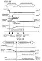
- Fig. 23 shows respective target values of operation magnitude of the throttle valve 2, the lifting magnitude of the exhaust valve 5, the spark ignition timing of the spark ignition plug 4 and the fuel injection pulse width of the fuel injector 3 in steady state in time sequence (toward upward in the drawing, increasing of open angle of the throttle valve, increasing of the lifting magnitude, advancing of the spark ignition timing and increasing of the fuel injection pulse width are shown).
- the throttle valve 2 On the basis of the switching demand from the compression ignition mode operation to the spark ignition mode operation, at first, the throttle valve 2 is fully closed or substantially fully closed for returning the air/fuel ratio toward stoichiometric value. Then, the lifting magnitude of the exhaust valve 5 is increased for reducing internal EGR. Then, the spark signal is turned ON for switching combustion mode to the spark ignition mode by advancing the spark signal per engine cylinder starting from the engine cylinder, from which the exhaust gas in the combustion chamber by the internal EGR is discharged. It should be noted that, at this time, since pumping loss is increased and combustion efficiency is lowered, the fuel injection pulse width during spark ignition mode operation is increased from the fuel injection pulse width during compression ignition mode to eliminate abrupt variation of the engine output torque.
- Fig. 24 shows intake air flow rate and the air/fuel ratio in the engine cylinder 12 upon execution of the shown control by the exhaust control unit 10A, NO x concentration upstream and downstream of the catalytic converter 7 in time sequence (toward upward of the drawing, increasing of intake air flow rate, making leaner the air/fuel ratio, increasing of NO x concentration).
- the intake air flow rate is decreased upon switching from the compression ignition mode to the spark ignition mode, and the air/fuel ratio is varied from lean (or stoichiometric value) to stoichiometric value.
- NO x downstream of the catalytic converter 7 is held constant before and after switching.
- NO x upstream of the catalytic converter 7 is increased upon switching to the spark ignition mode operation.
- Fig. 25 shows one example for controlling the exhaust air/fuel ratio toward stoichiometric value during compression ignition mode operation by the exhaust control unit 10A.
- the exhaust control unit 10A performs auxiliary fuel injection twice to perform by combining the air/fuel ratio during expansion stroke to the exhaust stroke in compression ignition mode operation to control the air/fuel ratio toward stoichiometric value.
- the fuel by auxiliary fuel injection does not contribute for development of the engine output torque. Therefore, the exhaust air/fuel ratio can be controlled toward stoichiometric value without causing abrupt variation of the torque.
- Fig. 26 shows one example of deterioration of the exhaust gas purification performance upon switching transition from the compression ignition mode operation to the spark ignition mode operation.
- Fig. 27 shows one example of the case of switching from the compression ignition mode to the compression ignition mode in the switching control upon acceleration state of the vehicle.
- combustion mode is switched from the compression ignition mode to the spark ignition mode by controlling the throttle valve open angle and the fuel injection pulse width toward the stoichiometric value in the compression ignition and reducing the exhaust gas in the engine cylinder by the internal EGR by increasing the lifting magnitude of the exhaust valve 5, and by advancing the spark signal. It should be preferred when torque shock at switching transition from the compression ignition to the spark ignition is significant, the torque shock can be reduced by setting the advancing angle of the spark ignition timing smaller than the target value.
- Fig. 28 shows the intake air flow rate, the air/fuel ratio and NO x amount upstream and downstream of the catalytic converter when the shown control is performed by the switching control portion 1102.
- the intake air flow rate is increased associating with demand for acceleration, and the air/fuel ratio is varied from lean to stoichiometric value.
- NO x amount downstream of the catalytic converter 7 is constant before and after switching of the combustion mode.
- NO x amount upstream of the catalytic converter 7 is abruptly increased after switching to the spark ignition mode operation.
- Fig. 29 shows an example where deterioration of the exhaust gas purification performance upon switching of the combustion mode.
- spark ignition is effected under lean air/fuel mixture condition to cause impulsive increase of the discharge amount of NO x upon switching from the compress ion ignition mode to the spark ignition mode.
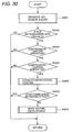
- Fig. 30 is an operational flowchart for preventing deterioration of the exhaust gas purification performance by detecting abnormality of combustion in compression ignition mode operation by means of the NO x sensor and improving combustion or inhibiting the compression ignition at the occurrence of deterioration of combustion.
- diagnosis of the NO x sensor 8 and the catalytic converter 7 is performed. This will be discussed later.
- the diagnosis is performed by the NO x sensor diagnosing means provided in the exhaust control unit 10A for diagnosing abnormality of the NO x sensor 8.
- step 3002 check is effected if failure of the NO x sensor 8 and fatigue of the catalytic converter is caused or not. If failure or fatigue is not caused, namely answer at step 3002 is YES, the process is advanced to step 3003. On the other hand, failure or fatigue is caused, the sequence of operation is terminated.
- step 3003 check is effected whether the current operation mode is the compression ignition mode and the air/fuel ratio is lean. If the current operation mode is the compression ignition mode and the air/fuel ratio is lean, namely the answer at step 3003 is YES, the process is advanced to step 3004. On the other hand, the current operation mode is nor the compression ignition mode or the air/fuel mixture is not lean, the sequence of operation is terminated.
- the NO x detection value is compared with the combustion deterioration threshold value NO x HL.
- the combustion deterioration threshold value NO x HL is a value determined by a detection criterion. If the NO x detection value is greater than or equal to the combustion deterioration threshold value NO x HL, namely the answer at step 3004 is YES, the process id advanced to step 3005. On the other hand, when the NO x detection value is less than the combustion deterioration threshold value NO x HL, the sequence of operation is terminated.
- control is performed for atomization of the fuel or homogenizing the air/fuel mixture in order to improve combustion in the compression ignition mode
- the exhaust control unit 10A includes combustion deterioration detecting means for detecting deterioration of combustion on the basis of the detection value of the NO x sensor 8 in the compression ignition mode operation, and combustion improvement control means for effecting improvement of combustion in the compression ignition mode when deterioration of combustion is detected by the combustion deterioration detecting means.
- combustion improvement control means controls the air/fuel ratio so that the output of the air/fuel ratio sensor 6 indicates the stoichiometric value.
- a fuel pressure is increased to be higher than normal condition, or a tumble control value or swirl control valve is . adjusted toward closing side than normal condition to enhance swirl flow in the combustion chamber.
- the air/fuel ratio upon compression ignition is adjusted toward lean side or EGR amount is increased to implement control for homogenizing the air/fuel mixture. If combustion is still not improved (when the NO x detection value is less than or equal to the predetermined value and abnormality of the NO x sensor 8 is judged), for burning deposit on the fuel injector 3, combustion mode is switched to the spark ignition to inhibit compression ignition until the high load operation is performed for a given period.
- step 3006 the process is advanced to step 3006 to check whether combustion improvement is effective or not. If combustion improvement is effective, the sequence of operation is terminated. When the combustion improvement is not effective, the process is advanced to step 3007 to control the air/fuel ratio so that the output of the air/fuel ratio sensor 6 indicates stoichiometric value even in the compression ignition mode operation for purification of the exhaust gas by the catalytic converter 7.
- ECU 10 in the shown embodiment includes the diagnosis unit 10B to perform diagnosis of fatigue of the NO x sensor 8 on the basis of the output signal of the NO x sensor 8 provided at a position downstream of the catalytic converter in order to prevent deterioration of the exhaust gas purification performance.
- diagnosis of the NO x sensor performed at step 3001 of Fig. 30 on the basis of the NO x detection value during fuel cut-off condition by interrupting fuel injection during deceleration state by fuel cut-off means in ECU 10 as illustrated in Fig. 31. Namely, since combustion is not effected during fuel cut-off state, NO x is not discharged. Thus, the NO x detection value becomes 0 during fuel cut-off state, the air/fuel ratio in the catalytic converter becomes lean upon fuel recovery by fuel recovery means in ECU 10 to frequently discharge a little amount of NO x .
- fatigue condition of the NO x can be judged by deriving a difference ⁇ NO x 1 between a lower limit value of the NO x detection value during fuel cut-off and the NO x detection value during fuel recovery, more particularly a peak value of NO x immediately after fuel recovery and checking whether the difference is smaller than or equal to the predetermined value.
- diagnosis of fatigue of the catalytic converter performed at step 3001 of Fig. 30 may be performed using respective outputs of the air/fuel ratio sensor 6 located upstream side of the catalytic converter 7 and the NO x sensor 8 located downstream side of the catalytic converter 7 as a relationship between the air/fuel ratio upstream side of the catalytic converter, the oxygen storage amount in the catalytic converter and the NO x detection amount in the normal state of catalytic converter as shown in Fig. 32, for example. If the catalytic converter 7 is normal, even when the air fuel ratio is offset toward lean side or rich side from the stoichiometric value, little variation is caused in NO x amount downstream of the catalytic converter since oxygen is stored in the catalytic converter 7.
- the air/fuel ratio control means provided in ECU 10 controls the air/fuel ratio so that the output of the air/fuel ratio sensor 6 becomes closer to the target air/fuel ratio.
- the diagnosis unit 10B performs diagnosis for detecting fatigue of the catalytic converter on the basis of the output signal of the NO x sensor 8 when the target air/fuel ratio is set at stoichiometric value. For example, when a correlation between variation amplitude of the air/fuel ratio and the NO x detection value exceeds the predetermined value, or when a power of a high frequency characteristics when the NO x detected value is subject to frequency conversion, exceeds a predetermined value, fatigue of the catalytic converter is detected.
- diagnosis unit 10B detects the detection value of the NO x sensor 8 during the compression ignition mode operation and detection in deterioration of combustion is performed from comparison with the combustion deterioration threshold value. More particularly, when the output of the air/fuel ratio sensor 6 indicates lean mixture condition, combustion deterioration detecting means for performing detection of the combustion deterioration in compression ignition including the diagnosis unit 10B detects deterioration of combustion through comparison.
- each embodiment of the present invention achieves the following functions with the construction set forth above.
- the NO x sensor 8 is arranged downstream side of the catalytic converter in the exhaust passage 13 for monitoring exhaust gas purification condition upon transition in switching combustion mode between the spark ignition mode and the compression ignition mode, during spark ignition mode and during compression ignition mode for preventing deterioration of exhaust gas purification performance during each combustion mode operation and at switching transition. Furthermore, since the diagnosis unit 10B of ECU 10 can perform diagnosis of the NO x sensor 8 and the catalytic converter 7 and diagnosis of combustion upon compression ignition, deterioration of exhaust gas purification performance even in fatigue of each component can be successfully prevented.
- the foregoing construction to prevent deterioration of the exhaust gas purification performance by ECU 10 can be a minimum system in the compression self-ignition engine, it contributes for lowering of manufacturing cost of the engine.
- a method for increasing the internal EGR amount by increasing enclosed exhaust gas amount by varying the lifting magnitude and the lifting period in the intake and exhaust valves 5 during compression ignition mode operation in Fig. 6. It is also possible to perform control of the internal EGR by a method of increasing the internal EGR by blowing back the exhaust gas toward intake side by increasing valve overlap of the intake and exhaust valves 5. Also, it is further possible to provide typical EGR passage connecting the air intake passage 12 and the exhaust passage 13 for external EGR for achieving the similar effect.
- step 3004 of Fig. 30 in order to avoid influence of noise of the NO x sensor 8, it is possible to compare weighted average value of the detection value of NO x and the predetermined value. Furthermore, as shown in Fig. 34, it is possible to transit from step 3004 to step 3005 when the NO x detection value exceeds NO x HL for a period longer than the predetermined period TNO x .
- control system of the compression ignition engine performs exhaust control and diagnosis on the basis of the output signal of the NO x sensor provided at the position downstream of the catalytic converter.
- the engine can be constructed with the minimum system with successfully preventing deterioration of exhaust gas purification performance upon the compression ignition mode operation in addition to switching transition of the combustion mode.
- diagnosis of NO x sensor and the catalytic converter can also be performed.
Abstract
Description
- The present invention relates to a controller or control system of a compression ignition engine. Particularly, the present invention relates to the controller of the compression ignition engine for preventing any deterioration in exhaust gas purification at a transition between spark ignition operation and compression ignition operation and during the compression ignition.
- The conventional lean-burn engines can improve fuel economy as the result of the effect of pumping loss decrease, and the like.
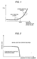
- However, there is a problem that NOx during the lean operation cannot be purified with three way catalyst. Therefore, the technology of a compression ignition engine which can suppress the NOx of engine out to several ppms in the lean mixture condition is proposed as one of the solutions of this problem (for instance, see Japanese Patent Application Laid-Open No. Sho 62-15722 Official Gazette, etc.). The compression ignition engine which has been described in the Official Gazette, by charging a pre-mixed air/fuel mixture for self-ignition, enables combustion at a combustion temperature lower than the temperature 1800 °K at which NOx generates (FIG. 1).
- However, it should be difficult to achieve the compression ignition at the time of engine starting, at the time of high load range of engine operation or the like and it is needed to switch the compression ignition range of engine operation, and the spark ignition range by a sparking plug depending upon the operation range or the state of the engine, as pointed out also with the Official Gazette (FIG. 2). The technology of the controller of the compression ignition engine which achieves this has been proposed (for instance, see Japanese Patent Application Laid-Open No. Hei 11-6435 Official Gazette). The compression ignition engine which has been described in this Official Gazette detects ignition timing based on an ionic current within a combustion chamber. Abnormal combustion is prevented by switching the combustion when a difference between the detected ignition timing and the spark ignition timing of a sparking plug becomes lower than a predetermined value. In another way, NOx under exhaust is detected, and the combustion is switched based on the change in the density of NOx. This technology prevents the combustion from becoming unstable (as proposed technology, see Japanese Patent Application Laid-Open No. Hei 11-336600). At this time, the deterioration in exhaust gas purification due to the miss-firing can be prevented by appropriately judging the timing of the switching.
- By the way, the catalyst which purifies the exhaust is not considered even though the conventional technology can prevent the deterioration in exhaust gas purification due to the abnormal combustion possibly caused in transition between the compression ignition and the spark ignition. Therefore, even in the state that the exhaust cannot be purified with the catalyst, the switching for the combustion is carried out, and it occurs a possibility to deprave the exhaust discharged in atmosphere. Namely, if the air/fuel ratio becomes excessively lean condition at the time of switching when the three way catalyst is provided in an exhaust pipe, NOx is exhausted as it is without being purified. On the contrary, if the air/fuel ratio becomes excessively rich condition, HC and CO are exhausted without being purified.
- Moreover, when the compression ignition is carried out in a lean air/fuel ratio, NOx cannot be purified with the three way catalyst. Therefore, it necessitates any means by which NOx exhausted from the engine at this time is prevented from deteriorating.
- That is, the inventors of the present invention have found that it is possible to monitor the fact that the exhaust gas is purified with the catalyst at the switching transition between the spark ignition mode operation and the compression ignition mode operation by using a three way catalyst and an NOx detector located at the downstream side of the three way catalyst, and it is possible to monitor the fact that the combustion aggravates also at the time of the compression ignition mode operation. They found that on the basis of this knowledge a system which achieves this can be provided with a minimum system structure. The above-mentioned prior art techniques do not have at all special consideration about this.
- The present invention has been worked out in view of the problems set forth above. One object of the present invention is to provide a control system for a compression injection engine which can prevent deterioration in exhaust purification at the time of the switching of combustion between spark ignition and compression ignition, at the time of the spark ignition combustion and the compression injection combustion, and can diagnose any deterioration of an NO x detector and a three way catalyst.
- In order to accomplish the above-mentioned object, a control system for a compression ignition engine can comprise:
- a catalytic converter installed within an exhaust passage of the compression ignition engine for compressing and igniting a pre-mixture of a fuel and air;
- an air/fuel ratio detector for detecting an air/fuel ratio at upstream side of the catalytic converter; and/or
- an NOx detector for detecting NOx at downstream side of the catalytic converter.
-
- The control system for the compression ignition engine according to the present invention, constructed as set forth above, can be provided with the NOx detector located downstream side of the catalytic converter. Since engine control is performed on the basis of the Nox detection value, a minimum system of the compression ignition engine can be constructed. Furthermore, with the construction set forth above, prevention of deterioration of exhaust gas purification performance can be achieved upon switching of combustion mode between spark ignition and compression ignition in addition to combustion in the spark ignition mode and compression ignition mode, and prevention of deterioration of exhaust gas purification performance by diagnosis of the Nox sensor, the catalytic converter and so forth.
- On the other hand, the particular mode of implementation of the control system of the compression ignition engine according to the present invention may use an output signal of the NOx detector for preventing deterioration of exhaust gas purification performance. In the alternative, the control system may prevent deterioration of exhaust gas purification performance upon switching transition of combustion mode between spark ignition and compression ignition, during spark ignition mode combustion and during compression ignition mode combustion.
- In another aspect of the invention, the control system may further comprise:
- combustion mode switching means for switching between a spark ignition mode and compression ignition mode;
- exhaust deterioration factor predicting means for predicting a factor causing deterioration of exhaust gas purification performance on the basis of an NOx detection value upon switching transition of the combustion mode; and/or
- switching learning means for leaning control amount and control object of the combustion mode switching means on the basis of the factor causing deterioration of exhaust gas purification performance. More particularly, the switching learning means can learn a spark ignition timing, a throttle valve control amount, a fuel injection amount, a fuel cut-off period before switching to the compression ignition mode combustion, one of a target intake air flow rate and/or a target EGR amount or an engine operational range for switching combustion mode between the spark ignition mode combustion and the compression ignition mode combustion.
-
- In a further aspect of the present invention, the control system can perform fuel injection between an expansion stroke and an exhaust stroke in the compression ignition mode combustion. The control system may comprise:
- air/fuel ratio control means for controlling an output of the air/fuel ratio detector toward a target air/fuel ratio; and/or
- a target air/fuel ratio calculating means for calculating the target air/fuel ratio for optimizing purification ratio of the catalytic converter,
- the target air/fuel ratio calculating means calculates the target air/fuel ratio on the basis of an output signal of the NOx detector. The control system may temporarily sets the target air/fuel ratio rich side when the NOx detection value exceeds a predetermined value. The control system may comprise NOx detector diagnosis means for diagnosing abnormality of the NOx detector for controlling the air/fuel ratio so that an output of the air-fuel ratio detector becomes stoichiometric value. The control system may further comprise combustion deterioration detecting means for detecting deterioration of combustion on the basis of an NOx detection value in the compression ignition mode combustion. The combustion deterioration detecting means may detect deterioration of combustion in the compression ignition mode combustion when an output of the air/fuel ratio detector indicates a lean mixture condition. The control system may further comprise combustion improvement control means for controlling improvement of combustion in the compression ignition mode when deterioration of combustion is detected by the combustion deterioration detecting means. The control system may control the air/fuel ratio so that the output of the air/fuel ratio detector becomes stoichiometric value when deterioration of combustion is detected by the exhaust deterioration detecting means after implementation of the combustion improvement control means. The control system may further comprise air/fuel ratio detector diagnosing means for detecting abnormality of the air/fuel ratio detector, for correcting a fuel injection amount on the basis of the output signal of the NOx detector when abnormality of the air/fuel ratio detector is detected. The control system thus prevents deterioration of exhaust gas purification performance by detecting fatigue of at least one of the NOx detector and the catalytic converter.
-
- On the other hand, the control system may comprise fuel cut-off means for interrupting fuel injection during deceleration, and fatigue of NOx detector may be detected on the basis of the output signal of the NOx detector during fuel cut-off. The control system may comprise fuel recovery means for recovering fuel injection after fuel cut-off, abnormality of the NOx detector may be judged when a difference the NOx detection value during fuel recovery and the NOx detection value during fuel cut-off is less than or equal to a predetermined value. The control system may further comprise air/fuel ratio control means for controlling air/fuel ratio so that an output of the air/fuel ratio detector becomes close to a target air/fuel ratio, for diagnosis of fatigue of the catalytic converter on the basis of the output signal of the NOx detector when the target air/fuel ratio is set at stoichiometric value.
- In addition, an automotive vehicle may have a control system for a compression ignition engine constructed as set forth above.
- The present invention will be understood more fully from the detailed description given hereinafter and from the accompanying drawings of the preferred embodiment of the present invention, which, however, should not be taken to be limitative to the invention, but are for explanation and understanding only.
- In the drawings:
- Fig. 1 is a view showing the relationship between combustion temperature and the amount of NOx exhaust in spark ignition operation and compression ignition operation;
- Fig. 2 is a view showing a spark ignition operation area and a compression ignition operation aria or an area which can be switched;
- Fig. 3 is a system configuration view when a control system for a compression ignition engine according to an embodiment of the present invention is applied to a cylinder-injection-of-fuel engine;
- Fig. 4 is a view showing one-cycle control at the time of spark ignition operation due to the use of the engine control device of Fig. 3;
- Fig. 5 is a view showing one-cycle control at the time of compression ignition operation due to the use of the engine control device of Fig. 3;
- Fig. 6 is a view showing exhaust valve profiles at the time of the spark ignition and compression ignition operations due to the use of the engine control device of Fig. 3;
- Fig. 7 is a block diagram of air/fuel ratio control based on an air/fuel ratio and an NOx detection value due to the use of the engine control device of Fig. 3;
- Fig. 8 shows a chart an air/fuel ratio and an NOx detection value at the time of the spark ignition operation due to the use of the engine control device of Fig. 3;
- Fig. 9 is a view to showing an example of an output from a target air/fuel ratio calculating part in Fig. 7;
- Fig. 10 is a view showing an example of calculation for the amount of correction in a fuel injection amount calculating part in Fig. 7 at the time of the break-down of an air/fuel ratio sensor;
- Fig. 11 is a control block view a switching control portion by an exhaust controller in Fig. 3;
- Fig. 12 is a view
showing control signal 1 at the time of the combustion switching control in Fig. 11 (to the compression ignition from the spark ignition); - Fig. 13 shows
outputs 1 from various sensors at the time of the normal condition in Fig. 12; - Fig. 14 shows output 2 from various sensors at the time of the abnormal condition due to air amount control error in Fig. 12;
- Fig. 15 shows
output 3 from various sensors at the time of the abnormal condition due to EGR control error in Fig. 12 - Fig. 16 is an operation flow chart of exhaust control in Fig. 11;
- Fig. 17 is an operation flow chart of a combustion judgment part in Fig. 11;
- Fig. 18 is an operation flow chart of a combustion switching control part in Fig. 11;
- Fig. 19 is an operation flow chart of a switching leaning part in Fig. 11;
- Fig. 20 is a view showing control signal 2 at the time of the combustion switching control in Fig. 11 (to the compression ignition from the spark ignition).
- Fig. 21 shows
output 1 from various Fig. as forsensor outputs 1 of Fig. 20; - FIG. 22 is a view to which various sensor outputs 2 in the abnormal circumstances which depends on fuel recover control error of Fig. 20;
- FIG. 23 is a view to which control signal 1 at the combustion switch control of Fig. 11 (jump spark ignition from the compression ignition) is shown;
- FIG. 24 shows
sensor outputs 1 in normal condition in Fig. 23; - FIG. 25 is a view to which one-cycle control when the exhaust controller of Fig. 23 drives the compression ignition;
- FIG. 26 is a view to which various sensor outputs 2 in the abnormal circumstances which depends on the fuel control mistake of Fig. 23;
- FIG. 27 is a view to which control signal 2 at the combustion switch control of Fig. 11 (jump spark ignition from the compression ignition) is shown;
- FIG. 28 is
shows sensor outputs 1 in normal condition in Fig. 27; - FIG. 29 is a view to which various sensor outputs 2 in the abnormal circumstances which depends on the control mistake of the fuel control mistake or the ignition time of Fig. 27 are shown;
- FIG. 30 is an operation flow chart of the exhaust control when the compression ignition is driven with the engine control device to which the diagnosis device of Fig. 3 is comprised.
- FIG. 31 is a view to which the NOx sensor diagnosis with the diagnosis device of Fig. 30;
- FIG. 32 is a view to which the catalyst diagnosis of the three way catalyst with the diagnosis device of Fig. 30 when it is normal;
- FIG. 33 is a view to which the catalyst diagnosis with the diagnosis device of Fig. 30 when the three way catalyst is abnormal; and
- FIG. 34 is a view to which the NOx sensor output when combustion with the diagnosis device of Fig. 30 deteriorates.
-
- The present invention will be discussed hereinafter in detail in terms of the preferred embodiment of the present invention with reference to the accompanying drawings. In the following description, numerous specific details are set forth in order to provide a thorough understanding of the present invention. It will be obvious, however, to those skilled in the art that the present invention may be practiced without these specific details. In other instance, well-known structure are not shown in detail in order to avoid unnecessary obscurity of the present invention.
- Hereafter, the embodiment of the present invention is explained referring to the drawing. Fig. 3 shows the embodiment of the present invention, in which is illustrated a system construction applied the preferred embodiment of a control system for a compression ignition engine.
- An
engine 50 is a compression ignition engine which compresses a premixed air/fuel mixture for self-ignition. An air-flow sensor 1 measuring an intake air flow rate and a throttle valve 2 adjusting intake air flow rate are provided at appropriate positions within anair induction passage 11, respectively. Also,injectors 3 for injecting fuel into the air induction passage or combustion chambers, spark ignition plugs 4 supplying ignition energy andvariable valves 5 controlling EGR amount to be recirculated into the combustion chambers, respectively, are provided forrespective engine cylinders 12. A three-waycatalytic converter 7 for purifying an exhaust gas, an air/fuel ratio sensor 6, such as O2 sensor as one embodiment of an air/fuel ratio detector, for detecting an air/fuel ratio from the exhaust gas at upstream side of thecatalytic converter 7, an NOx sensor 8 detecting NOx concentration at downstream side of thecatalytic converter 7 are provided in an exhaust passage. Furthermore, on acrankshaft 14, acrank angle sensor 9 for detecting or deriving a crank shaft angular position is provided. Signals from theair flow sensor 1, the air/fuel ratio sensor 6, the NOx sensor 8 and thecrank angle sensor 9 are input to an engine control unit (hereinafter referred to as ECU) 10, in which a microcomputer is provided for signal processing.ECU 10 includes anexhaust control unit 10A performing various control on the basis of an output signal of the NOx sensor 8 for preventing deterioration of exhaust gas purification performance, which will be discussed later, and adiagnosis unit 10B. As will be discussed later, theexhaust control unit 10A prevents deterioration in exhaust gas purification performance at the transition in combustion modes between spark ignition and compression ignition, during combustion in spark ignition and during combustion in compression ignition. On the other hand, thediagnosis unit 10B prevents deterioration of exhaust gas purification performance through diagnosis of fatigue of NOx sensor 8 and thecatalytic converter 7. - Fig. 4 illustrates relationship between a pressure within the combustion chamber, a fuel injection signal and a spark ignition timing in spark ignition mode operation under control by
ECU 10. - As shown, in normal spark ignition mode operation, the fuel is injected through the
fuel injector 3 in an induction stroke, and the fuel in the combustion chamber is ignited by thespark plug 4 in a compression stroke. - On the other hand, Fig. 5 illustrates a pressure within the combustion chamber, a fuel injection signal and so forth in compression ignition mode operation under control by
ECU 10. - Here, there are some methods in realizing the compression ignition mode operation. In the shown embodiment, as illustrated in Fig. 5, profiles of an
intake valve 5 and anexhaust valve 5 are varied to enclose the exhaust gas (internal EGR) in exhaust stroke. Then, into the exhaust gas enclosed within the combustion chamber, an auxiliary fuel is injected by thefuel injector 3 for compression to generate a radical. Next, in the compression stroke, a primary fuel is injected through thefuel injector 3 to cause self-ignition in the fuel. Namely,ECU 10 controls internal temperature within thecylinder 12 by internal EGR and can also control an ignition temperature by the auxiliary fuel injection and the primary fuel injection for appropriately controlling compression ignition timing. - Figs. 6(a) and 6(b) show profiles of the intake and
exhaust valves 5 for controlling the internal EGR. Fig. 6(a) shows a method for increasing the internal EGR by enclosing the exhaust gas by reducing a magnitude of valve lift of the intake andexhaust valves 5 during compression ignition mode operation. On the other hand, Fig. 6(b) shows a method for increasing the internal EGR by enclosing the exhaust gas by setting the lifting period of theexhaust valve 5 shorter than the lifting period of the intake valve during the compression ignition mode operation. - As shown in Fig. 1, during compression ignition mode operation, little amount of NOx is generated. Furthermore, since generation of NOx has little dependency on air/fuel ratio, exhaust gas purification performance will not deteriorate even in lean air/fuel mixture condition during compression ignition mode operation. Namely, the shown embodiment of the
engine 50 is designed for reducing exhaust gas to be discharged to the atmosphere by controlling air/fuel ratio toward stoichometric value during spark ignition mode operation, and for reducing exhaust gas to be discharge to the atmosphere by controlling air/fuel ratio toward stoichiometric value or lean during compression ignition mode operation. - Here, discussion will be given for air/fuel ratio control during spark ignition mode operation on the basis of a detection value of NOx of the NOx sensor 8 located downstream side of the
catalytic converter 7. - Fig. 7 is a control block diagram of an air/fuel ratio control system by the
exhaust control unit 10A inECU 10. -
ECU 10 includes a fuelinjection calculating portion 701 and a target air/fuelratio calculating portion 702. In order to permits theexhaust control unit 10A to purify the exhaust gas at high efficiency by thecatalytic converter 7, it becomes necessary to appropriately control an oxygen storage amount in thecatalytic converter 7. Therefore, the target air/fuelratio calculating portion 702 derives a target air/fuel ratio for optimizing purification efficiency in thecatalytic converter 7 on the basis of the detection value of NOx from the NOx sensor 8 to output to the fuelinjection calculating portion 701 as one embodiment of the air/fuel ratio control means. The fuelinjection calculating portion 701 derives a fuel amount to control an actual fuel injection amount detected by the air/fuel ratio sensor 6 toward the target air/fuel ratio to output to thefuel injector 3, and thus controls oxygen storage amount in thecatalytic converter 7. - Here, Fig. 8 shows oxygen storage amount and NOx detection amount when the detected value of the air/fuel ratio sensor 6 indicates lean mixture condition. As shown, when the air/fuel ratio is lean and if the oxygen storage amount reaches a storage limit, purification of NOx by the catalytic converter becomes impossible. Therefore, detection value of NOx is increased.
- As a solution for this, when the detected value of the NOx sensor 8 exceeds a predetermined value NOxHLe, the
exhaust control unit 10A varies the target air/fuel ratio for feedback control of air/fuel ratio (λ-control) toward rich side temporarily, and subsequently returns the target air/fuel ratio to the normal target air/fuel ratio for controlling the oxygen storage amount. It should be noted that some NOx sensors have capability of measurement of oxygen concentration simultaneously with NOx amount. In such case, feedback control of the air/fuel ratio is performed by setting the target air/fuel ratio so that oxygen concentration on downstream side of the catalytic converter becomes constant. If NOx is detected, the target value of the oxygen concentration is shifted toward rich side until the detection value of NOx sensor 8 becomes zero. Even in this manner, the oxygen storage amount can be controlled appropriately. - On the other hand,
ECU 10 corrects fuel injection amount to control the air/fuel ratio toward the target air/fuel ratio. However, when abnormality of the air/fuel sensor 6 is judged or detected, it becomes not possible to perform control the air/fuel ratio toward the target air/fuel ratio. Therefore, theexhaust control unit 10A reduces the exhaust gas on the basis of the NOx sensor 8 in the following manner when abnormality of the air/fuel sensor 6 is detected. - Fig. 10 shows a relationship between the NOx detection value and the fuel correction amount by the
exhaust control unit 10A ofECU 10 upon failure of the air/fuel sensor. - The
exhaust control unit 10A includes an air/fuel ratio sensor diagnosing means for detecting abnormality of the air/fuel ratio sensor 6. As shown, upon diagnosis of abnormality of the air/fuel ratio sensor 6, the fuel injection amount is corrected on the basis of the output signal of the NOx sensor 8. Namely, when the detection value of NOx is less than or equal to the predetermined value NOxHLe, fuel correction amount is reduced by a given rate. On the other hand, when the NOx detection value exceeds the predetermined value NOxHLe, fuel correction is performed by a given amount toward rich side, and subsequently, the fuel correction amount is increased at a given rate. By this, while the air/fuel ratio becomes slightly lean, excessive offset of the air/fuel ratio may not be caused to prevent deterioration of exhaust gas purification performance. - Next, discussion will be given for exhaust control upon transition in combustion mode between the spark ignition and compression ignition by the
exhaust control unit 10A ofECU 10. - Fig. 11 is a block diagram showing a control system for preventing deterioration of the exhaust gas purification performance upon switching of combustion mode by the
exhaust control unit 10A. - The
exhaust control unit 10A includes acombustion judgment portion 1101, a switchingcontrol portion 1102, an exhaustdeterioration detecting portion 1103 and aswitching learning portion 1104. - The
combustion judgment portion 1101 reads out an engine revolution speed or engine speed, an engine load, such as air intake flow rate, an accelerator depression magnitude, an engine coolant temperature, a catalyst temperature and so on and makes judgment whether switching of the combustion mode is to be performed or not for outputting a switching demand to the switchingcontrol portion 1102 on the basis of the result of judgment. For example, as shown in Fig. 2, thecombustion judgment portion 1101 is set a map defining a range, in which compression ignition is possible, in relation to the engine revolution speed and the engine load. The range capable of combustion ignition will be hereinafter referred to as "combustion ignition range". Thecombustion judgment portion 1101 derives a target engine load on the basis of the accelerator depression amount. When the instantaneous engine speed and the target engine load falls within the compression ignition range, thecombustion judgment portion 1101 makes judgment whether switching from the spark ignition mode to compression ignition mode is to be performed or not. It should be noted that, in order to prevent deterioration in exhaust gas purification performance, switching of the combustion mode from the spark ignition mode to the compression ignition mode is inhibited when the coolant temperature or the catalyst temperature does not reach a predetermined criterion value even when the engine revolution speed and the engine load falls within the compression ignition range. - The switching
control portion 1102 switches the combustion mode from the spark ignition mode to the compression ignition mode or from the compression ignition mode to the spark ignition mode in accordance with the switching demand, and outputs to theswitching learning portion 1104. - As will be discussed later, the exhaust
deterioration detecting portion 1103 is means for predicting an exhaust deterioration factor on the basis of the detection value of the NOx sensor 8 upon switching. The result of prediction is output to theswitching learning portion 1104. - As will be discussed later, the
switching learning portion 1104 learns control amounts (e.g. spark ignition timing, a throttle control amount, a fuel injection amount, a fuel cut period before switching to the compression ignition, a target air intake amount or a target EGR amount and so on) of the switchingcontrol portion 1102. In the alternative, by leaning control objects (e.g. combustion mode switching region for switching between the spark ignition mode combustion and the compression ignition mode combustion as judged by the combustion judgment portion 1101), deterioration of the exhaust gas purification performance can be prevented upon combustion mode switching transition. - By the foregoing control, even when offset is caused in the internal EGR amount due to secular change or other reason, the intake air flow rate is adjusted to ensure avoidance of rich mixture in relation to the internal EGR amount by learning. Also, since the internal EGR amount can be controlled for enabling switching to the compression ignition mode combustion, deterioration of exhaust gas purification performance can be successfully prevented.
- Fig. 12 shows one example of switching control in combustion mode switching transition from the spark ignition mode combustion to the compression ignition mode combustion by the switching
control portion 1102 of theexhaust control unit 10A, which is switching control in steady state (output being constant). - Respective target values of an operation magnitude of the throttle valve, a lifting magnitude of the
exhaust gas 5, a timing of a spark signal of thespark plug 4 and a fuel injection pulse width of thefuel injector 3 are shown in time sequence (toward upward in the drawing, increasing of open angle of the throttle valve, increasing of lifting magnitude, advancing of spark ignition timing, increasing of the fuel injection pulse width). - At first, a relationship between the internal EGR amount and the exhaust valve lifting magnitude EV1 or a lifting period of the
exhaust valve 5 is variable depending upon operating condition, such as the engine revolution speed, the engine load and so forth. Through experiments or simulation, relationship between the internal EGR amount and the exhaust valve lifting magnitude EV1 or the lifting period per operating condition has to be preliminarily derived and set in a form of map or model. - Here, when the internal EGR amount is increased by reducing valve lifting magnitude of the
exhaust valve 5, amount of fresh air flowing into theengine cylinder 12 is decreased to possibly make the air/fuel ratio rich. Such excessively rich air/fuel ratio may cause deterioration of exhaust gas purification performance by lowering of oxidation function in thecatalytic converter 7. Therefore, theexhaust control unit 10A prevents formation of rich air/fuel mixture by preliminarily opening the throttle valve 2 depending upon the internal EGR amount. - For this purpose, since the intake air flow rate comparable with the internal EGR amount is required to flow into the combustion chamber, the throttle valve 2 is driven to increase open angle by TV1. Since the internal EGR amount is variable per engine driving range or operation range. The throttle opening magnitude TV1 is preliminarily derived by experiments or simulation so that the air/fuel ratio is may not become rich as a feed-forward control amount read out from the map per operation range.
- After delay in adjustment of the intake air flow rate depending upon the intake air flow rate, the
engine cylinder 12 in expansion stroke is detected to shift the valve lifting magnitude of theexhaust valve 5 to the predetermined value before entering into the exhaust stroke to control the internal EGR to establish a condition permitting compression ignition mode combustion. Subsequently, the spark ignition timing of the relevant cylinder in compression ignition is retarded from a timing of self-ignition of the pre-mixture to switch the combustion mode from the spark ignition mode to the compression ignition. - Next, when the combustion mode is switched to the compression ignition. the target value of the air/fuel ratio is set to lean. More particularly, the throttle valve 2 is further opened to increase the intake air flow rate, and the fuel injection amount is reduced anticipating improvement of pumping loss component and improvement of combustion efficiency. At this time, it is desirable to develop a maximum torque by controlling compression ignition timing.
- Fig. 13 shows the intake air flow rate, the air/fuel ratio in the exhaust gas discharged from the engine, NOx concentration upstream and downstream of the
catalytic converter 7 in time sequence when the shown embodiment of control is executed by theexhaust control unit 10A (in the drawings, toward upward in the drawing, increasing of the intake air flow rate, lean of air/fuel ratio and increasing of NOx concentration are indicated). - Under the shown embodiment of the control by the
exhaust control unit 10A, the intake air flow rate becomes constant during spark ignition mode combustion. After switching to the compression ignition mode combustion, the throttle valve 2 is opened to increase the intake air flow rate. On the other hand, the air/fuel ratio detected by the air/flow rate sensor 6 becomes stoichiometric value during the spark ignition mode operation and lean during the compression ignition mode operation. Furthermore, NOx amount upstream of thecatalytic converter 7 is reduced upon switching transition from the spark ignition mode to the compression ignition mode and thus is lowered to the same level as that during compression ignition mode operation after switching transition to the compression ignition mode. Therefore, NOx amount downstream of thecatalytic converter 7 can be maintained at the equal level before and after switching transition. - As set forth above, the exhaust control by the
exhaust control unit 10A is performed by opening the throttle valve 2 in the magnitude of TV1 in order to preventing the air/fuel ratio in theengine cylinder 12 from becoming rich. On the other hand, in order to control the internal EGR amount for switching to the compression ignition, the lifting magnitude of theexhaust valve 5 is reduced in the magnitude of EV1. These control amounts are adjusted upon shipping. It is thus possible that the control amounts become inappropriate due to secular change or other reason. - For example, as shown in Fig. 14, if an actual intake air flow rate flowing into the
engine cylinder 12 at the throttle valve open angle TV1 is large, the air/fuel ratio becomes leaner in the extent corresponding to increasing of the intake air flow rate. As a result, it becomes possible to temporarily cause thecatalytic converter 7 impossible to purify NOx generated during spark ignition mode combustion to impulsively discharge increased amount NOx. On the other hand, as shown in Fig. 15, if internal EGR amount is not appropriate at switching transition, delay can be caused in switching timing from the compression ignition mode to the spark ignition mode to impulsively discharge increased amount of NOx in transition of the air/fuel ratio to be lean. Such impulsive increase of NOx discharge amount will be hereinafter occasionally referred to as "NOx spike". - Therefore, the
exhaust control unit 10A is provided with the exhaustdeterioration detecting portion 1103 as shown in Fig. 11. In the exhaustdeterioration detecting portion 1103, the exhaust deterioration factor is analyzed by detecting NOx at switching transition to output result of analysis to theswitching learning portion 1104. - More particularly, the exhaust
deterioration detecting portion 1103 makes judgment whether discharging of NOx is caused due to offset in the intake air flow rate control or offset in the EGR control on the basis of the relationship between timing of occurrence of the NOx spike, combustion mode switching timing and output of the air/fuel ratio sensor upstream of the catalytic . converter. Then, in theswitching learning portion 1104, feed-forward control is performed so that when the NOx spike is detected before switching of combustion mode, the throttle valve open angle TV1 is reduced depending upon magnitude of the NOx spike. On the other hand, when the NOx spike is detected after switching of the combustion mode, the lifting magnitude EV1 of theexhaust valve 5 is increase depending upon magnitude of the NOx spike. - On the other hand, the
switching learning portion 1104 makes judgment the switching of the combustion mode is not possible when the value after learning exceeds a predetermined control range to update a combustion mode switching range map provided in thecombustion judgment portion 1101 to inhibit switching. It should be noted that the combustion mode switching range map may be the same map as shown in Fig. 2, or, in the alternative, may be other map in a sense that can implement combustion mode switching control without causing deterioration of exhaust purification performance. - Figs. 16 to 19 are flowcharts showing operation of the exhaust control by the
exhaust control unit 10A. Fig. 16 illustrates the control block of Fig. 11 in a form of flowchart. - At
step 1601, operating condition (the engine revolution speed, the accelerator depression magnitude, the coolant temperature, the catalyst temperature and so forth) is read out from various sensors. At step 1602, judgment is made whether the combustion mode is to be switched or not in thecombustion judgment portion 1101. Then, process is advanced to step 1603. - At step 1603, judgment is made whether combustion mode switching demand is present or not. If the combustion mode switching demand is present, namely the answer is YES at step 1603, the process is advanced to step 1604. Then, combustion mode is switched at the switching
control portion 1102. The process is then advanced to step 1605. It should be noted that when the combustion mode switching demand is not present as checked at step 1603, a sequence of operation is terminated. - At step 1605, judgment is made whether the switching of the combustion mode is completed or not. The process is not advanced to step 1606 until combustion mode switching control is completed. When switching is completed, namely answer is YES at step 1605, the process is advanced to step 1606 to learn the control amount of the switching
control portion 1102 or the combustion mode switching range in thecombustion judgment portion 1101 on the basis of the detection value of the NOx sensor 8, and then to terminate the sequence of operation. - Next, discussion will be given for operation in respective of the
combustion judgment portion 1101 at step 1602, switchingcontrol portion 1102 at step 1604 and theswitching learning portion 1104 at step 1606 with reference to the flowchart. - Fig. 17 is a flowchart showing the operation of the
combustion judgment portion 1101 of theexhaust control unit 10A. - At step 1701, a switching demand flag is cleared. At step 1702, judgment is made whether the current combustion mode is the spark ignition mode or not. If the current combustion mode is the spark ignition mode, namely the answer is YES, the process is advanced to step 1703. If the current combustion mode is not the spark ignition mode (compression ignition mode), the process is advanced to step 1706.
- At
steps step 1703, check is performed whether a stable compression ignition mode combustion control is possible or not by checking if the engine revolution speed is lower than or equal to a predetermined value, if the intake air flow rate is smaller than or equal to a predetermined value, if a variation amount of the accelerator depression magnitude falls within a predetermined range, if fluctuation of the engine revolution speed is smaller than or equal to a predetermined value and other conditions. If switching of the control mode is possible, the process is advanced to step 1704. Atstep 1704, check is performed whether the engine operating condition falls within the operation range permitting switching from the spark ignition mode to the compression ignition mode. Here, the range where deterioration of exhaust gas purification performance is not caused at switching transition from the spark ignition mode to the compression ignition mode, is defined in a form of a map with respect to the engine revolution speed and an engine output torque, for example, and the current operation range is checked if falls within the thus defined range. when the current operation range falls within the range not causing deterioration of exhaust gas purification performance, namely answer is YES, the process is advanced to step 1705. If stable compression ignition mode combustion control is not possible as checked atstep 1703, or, in the alternative, the current operation range does not fall within the range not causing deterioration of exhaust gas purification performance, the sequence of operation is terminated. - At
step 1705, a switching demand flag indicative of the switching demand from the spark ignition mode to the compression ignition mode is set ON. Then, the sequence of operation is terminated. - On the other hand, at step 1702, when the current combustion mode is the compression ignition mode, the process is advanced to step 1706 to check whether a compression ignition permitting condition is not satisfied or not. If the compression ignition permitting condition is not satisfied, the process is advanced to step 1708. On the other hand, if the compression ignition permitting condition is satisfied, the process is advanced to step 1707 to check whether deterioration of combustion is caused or not. At this step, checking of misfiring is performed on the basis of the signal of the
crank angle sensor 9 or other, and checking of abnormal combustion is performed on the basis of the signal of the NOx sensor 8. When deterioration of combustion is detected, namely the answer is YES as checked at step 1707, the process is advanced to step 1708 to set ON the switching demand flag for switching from the compression ignition to the spark ignition. Then, a sequence of operation is terminated. It should be noted that when deterioration of combustion is not detected, a sequence of operation is terminated. - Accordingly, the
combustion judgment portion 1101 of theexhaust control unit 10A issues the switching demand only in a range where switching can be performed without causing deterioration of the exhaust gas purification performance in addition to judgment whether compression ignition mode combustion is possible. Thus, deterioration of the exhaust gas purification performance during switching transition of the combustion mode can be successfully prevented. - On the other hand, during the compression ignition mode operation, deterioration of combustion is monitored so that the combustion mode is quickly returned to the spark ignition mode upon detection of deterioration of combustion. Therefore, deterioration of the exhaust gas purification performance can be prevented even during compression ignition mode operation. Furthermore, by using the output of the NOx sensor 8 in judgment of deterioration of combustion, a little deterioration of exhaust gas purification performance which cannot be perceived from increasing of NOx discharge amount due to non-uniformity of the mixture, fluctuation of engine revolution speed or other parameter, can be detected.
- Fig. 18 is a operational flowchart of one embodiment upon switching from the spark ignition mode to the compression ignition in the switching
control portion 1102 of theexhaust control unit 10A. - At step 1801, the target EGR amount is calculated for switching to the compression ignition mode combustion. The target intake air flow rate is set for preventing the mixture in the combustion chamber rich depending upon the target EGR amount. Then, at
step 1802, in order to realize the target EGR amount and the target intake air flow rate, the target throttle open angle TV1 for the throttle valve 2 and the target lifting magnitude EV1 of theexhaust valve 5 are set. - At step 1803, the
engine cylinder 12, at which switching of combustion mode is initiated, is set. At step 1804, the open angle of the throttle valve 2 will is increased in the extent of TV1. - At step 1805, the processes is held waiting until the engine cylinder set for initiation of switching enters into the expansion stroke. When entry into expansion stroke of the relevant engine cylinder, the process is advanced to step 1806 to reduce the lifting magnitude of the
exhaust valve 5 by EV1. Then, entry into compression stroke in therelevant engine cylinder 12 is waited. When the relevant engine cylinder enters into the compression stroke, the spark ignition timing is retarded from the compression ignition timing. Then, a sequence of operation is terminated. - Accordingly, the switching
control portion 1102 of theexhaust control unit 10A calculates an appropriate internal EGR per operation range to set the lifting magnitude of theexhaust valve 5 for assuring transition to the compression ignition mode. Furthermore, by setting the target intake air flow rate depending upon the internal EGR amount to preliminarily open the throttle valve to prevent the air/fuel ratio from becoming rich to cause deterioration of the exhaust gas purification performance. - Furthermore, by retarding the spark ignition timing from the compression ignition timing, even when failure is caused in compression ignition upon switching transition from the spark ignition to the compression ignition, ignition can be caused by the spark ignition at the retarded timing for preventing deterioration of the exhaust gas purification performance due to misfiring.
- Fig. 19 is a operational flowchart of the
switching learning portion 1104 of theexhaust control unit 10A. - At step 1901, judgment is made whether deterioration of the exhaust gas purification performance is caused during the spark ignition mode operation or not. If deterioration of the exhaust gas purification performance is caused, namely the answer at step 1901 is YES, the process is advanced to step 1902. On the other hand, if deterioration of the exhaust gas purification performance is not caused, the process is advanced to step 1903.
- At step 1902, learning is performed for reducing the target intake air flow rate. Namely, a factor for causing deterioration of the exhaust gas purification performance during spark ignition mode operation is excessively lean air/fuel mixture. Therefore, the target intake air flow rate is adjusted to be smaller. More particularly, by reducing the open angle EV1 of the throttle valve 2, deterioration of the exhaust gas purification performance can be avoided.
- At
step 1903, judgment is made whether deterioration of the exhaust gas purification performance in the compression ignition mode operation is caused or not. If deterioration of the exhaust gas purification performance is caused, namely when the answer atstep 1903 is YES, the process is advanced to step 1904. If deterioration of the exhaust gas purification performance is not caused, the process is advanced to step 1905. Deterioration of the exhaust gas purification performance during compression ignition mode operation can be caused by insufficiency of EGR to cause incapability of elevating the temperature in the engine cylinder for compression ignition. Therefore, in such case, learning is made to increase the target EGR amount at step 1904. More particularly, by reducing the lifting magnitude EV1 of theexhaust valve 5, deterioration of the exhaust gas purification performance can be avoided. - Next, at
step 1905, each learnt value set at step 1902 or 1904 is compared with a predetermined value determined by operation range of the throttle valve 2 and/or theexhaust valve 5 to check whether the learnt value is smaller than or equal to the predetermined value. If the learnt value is smaller than or equal to the predetermined value, namely the answer atstep 1905 is YES, the sequence of operation is terminated. On the other hand, when the learnt value is in excess of the predetermined value, the process is advanced to step 1906 to inhibit switching in the corresponding operational range of the engine. - Accordingly, the
switching learning portion 1104 of theexhaust control unit 10A can prevent deterioration of the exhaust gas purification performance by appropriately setting the control amount in intake air flow rate control upon spark ignition mode operation by learning and by appropriately setting the control amount of the internal EGR control during the compress ion ignition mode operation by learning. Furthermore, when a set value of the control amount by learning is in excess of the predetermined value range, switching in the relevant operational range of the engine is inhibited for preventing deterioration of the exhaust gas purification performance. - Here, in the
switching learning portion 1104, switching from the spark ignition mode to the compression ignition mode is essentially performed in the air/fuel mixture condition at stoichiometric value. However, there are some exceptions. - Fig. 20 shows one example of exceptions, and illustrates the case where fuel recovery after fuel cut-off operation is performed under compression ignition mode operation. Respective target values of operation magnitude of the throttle valve 2, the lifting magnitude of the
exhaust valve 5, the spark ignition timing of thespark ignition plug 4 and the fuel injection pulse width of thefuel injector 3 in switching control from the spark ignition mode to the compression ignition mode upon fuel recovery are shown in time sequence (toward upward in the drawing, increasing of open angle of the throttle valve, increasing of the lifting magnitude, advancing of the spark ignition timing and increasing of the fuel injection pulse width are shown). - Here, there is illustrated an example, in which fuel cut-off is effected during deceleration, and subsequently, the fuel recovery is performed under compression ignition mode operation. When the throttle valve 2 is fully closed or reduced the open angle close to fully closed position and when the engine revolution speed is decelerated to be lower than or equal to a predetermined value, fuel supply is started to generate a driving torque by the compression ignition to enclose exhaust gas by reducing lifting magnitude of the
exhaust valve 5 and by retarding the spark ignition timing of theengine cylinder 12, to which the fuel is injected, to transit to compression ignition. - Fig. 21 shows the intake air flow rate, the air/fuel ratio and NOx value upstream and downstream of the catalytic converter similar to Fig. 13.
- At first, since no NOx is generated during fuel cut-off, a NOx detection values upstream and downstream of the
catalytic converter 7 becomes 0. Accordingly, diagnosis and calibration of the NOx sensor 8 can be performed on the basis of the NOx value during fuel cut-off. This will be discussed later. - A problem to be encountered in switching, since combustion is not performed during fuel cut-off, the exhaust temperature can be lowered. Therefore, when fuel cut-off period is long, the compression ignition fails and the spark ignition by the retarded spark signal is effected for combustion to cause impulsive variation of the NOx concentration, as shown in Fig. 22. Accordingly, as shown in Fig. 21, a fuel cut-off period FC1 capable of fuel recovery under compression ignition is preliminarily derived through experiments or simulation so that fuel recovery is effected under the compression ignition if the fuel cut-off period falls within the predetermined fuel cut-off period (FC1), and otherwise, air/fuel ratio is controlled toward stoichiometric value to realize fuel recovery by spark ignition. When fuel recovery is performed under the compression ignition to impulsively increase NOx, learning is performed to shorten the duel cut-off period FC1 to further certainly prevent deterioration of the exhaust gas purification performance.
- Next, conversely from switching transition from the spark ignition mode to the compression ignition mode set forth above, discussion will be given for switching control from the compression ignition to the spark ignition by the
switching learning portion 1104 of theexhaust control unit 10A. - Fig. 23 shows respective target values of operation magnitude of the throttle valve 2, the lifting magnitude of the
exhaust valve 5, the spark ignition timing of thespark ignition plug 4 and the fuel injection pulse width of thefuel injector 3 in steady state in time sequence (toward upward in the drawing, increasing of open angle of the throttle valve, increasing of the lifting magnitude, advancing of the spark ignition timing and increasing of the fuel injection pulse width are shown). - On the basis of the switching demand from the compression ignition mode operation to the spark ignition mode operation, at first, the throttle valve 2 is fully closed or substantially fully closed for returning the air/fuel ratio toward stoichiometric value. Then, the lifting magnitude of the
exhaust valve 5 is increased for reducing internal EGR. Then, the spark signal is turned ON for switching combustion mode to the spark ignition mode by advancing the spark signal per engine cylinder starting from the engine cylinder, from which the exhaust gas in the combustion chamber by the internal EGR is discharged. It should be noted that, at this time, since pumping loss is increased and combustion efficiency is lowered, the fuel injection pulse width during spark ignition mode operation is increased from the fuel injection pulse width during compression ignition mode to eliminate abrupt variation of the engine output torque. - Fig. 24 shows intake air flow rate and the air/fuel ratio in the
engine cylinder 12 upon execution of the shown control by theexhaust control unit 10A, NOx concentration upstream and downstream of thecatalytic converter 7 in time sequence (toward upward of the drawing, increasing of intake air flow rate, making leaner the air/fuel ratio, increasing of NOx concentration). - As illustrated, the intake air flow rate is decreased upon switching from the compression ignition mode to the spark ignition mode, and the air/fuel ratio is varied from lean (or stoichiometric value) to stoichiometric value. On the other hand, NOx downstream of the
catalytic converter 7 is held constant before and after switching. However, NOx upstream of thecatalytic converter 7 is increased upon switching to the spark ignition mode operation. - Fig. 25 shows one example for controlling the exhaust air/fuel ratio toward stoichiometric value during compression ignition mode operation by the
exhaust control unit 10A. - The
exhaust control unit 10A performs auxiliary fuel injection twice to perform by combining the air/fuel ratio during expansion stroke to the exhaust stroke in compression ignition mode operation to control the air/fuel ratio toward stoichiometric value. - The fuel by auxiliary fuel injection does not contribute for development of the engine output torque. Therefore, the exhaust air/fuel ratio can be controlled toward stoichiometric value without causing abrupt variation of the torque.
- Fig. 26 shows one example of deterioration of the exhaust gas purification performance upon switching transition from the compression ignition mode operation to the spark ignition mode operation.
- This shows the condition at the occurrence of deterioration of NOx emission caused by effecting of the spark ignition before returning the air/fuel ratio to the stoichiometric value. Accordingly, in such case, by learning to increase the fuel amount adapting to the air/fuel ratio shown in Fig. 25, it becomes possible to prevent deterioration of the exhaust gas purification performance. In the alternative, while it takes longer period in switching transition, similar effect can be attained by providing a delay in timing for advancing the spark ignition timing.
- Next, Fig. 27 shows one example of the case of switching from the compression ignition mode to the compression ignition mode in the switching control upon acceleration state of the vehicle.
- Namely, combustion mode is switched from the compression ignition mode to the spark ignition mode by controlling the throttle valve open angle and the fuel injection pulse width toward the stoichiometric value in the compression ignition and reducing the exhaust gas in the engine cylinder by the internal EGR by increasing the lifting magnitude of the
exhaust valve 5, and by advancing the spark signal. It should be preferred when torque shock at switching transition from the compression ignition to the spark ignition is significant, the torque shock can be reduced by setting the advancing angle of the spark ignition timing smaller than the target value. - Fig. 28 shows the intake air flow rate, the air/fuel ratio and NOx amount upstream and downstream of the catalytic converter when the shown control is performed by the switching
control portion 1102. - The intake air flow rate is increased associating with demand for acceleration, and the air/fuel ratio is varied from lean to stoichiometric value. On the other hand, while NOx amount downstream of the
catalytic converter 7 is constant before and after switching of the combustion mode. NOx amount upstream of thecatalytic converter 7 is abruptly increased after switching to the spark ignition mode operation. - Fig. 29 shows an example where deterioration of the exhaust gas purification performance upon switching of the combustion mode.
- Here, it can be appreciated that spark ignition is effected under lean air/fuel mixture condition to cause impulsive increase of the discharge amount of NOx upon switching from the compress ion ignition mode to the spark ignition mode.
- Accordingly, in order to prevent deterioration of the exhaust gas purification performance, it becomes necessary to learn to increase enrichment amount of the fuel injection amount or delaying advancing timing of the spark ignition timing as in the switching
control portion 1102. - Next, discussion will be given for the exhaust control during the compression ignition mode operation by the
exhaust control unit 10A. - Fig. 30 is an operational flowchart for preventing deterioration of the exhaust gas purification performance by detecting abnormality of combustion in compression ignition mode operation by means of the NOx sensor and improving combustion or inhibiting the compression ignition at the occurrence of deterioration of combustion.
- At step 3001, diagnosis of the NOx sensor 8 and the
catalytic converter 7 is performed. This will be discussed later. For example, the diagnosis is performed by the NOx sensor diagnosing means provided in theexhaust control unit 10A for diagnosing abnormality of the NOx sensor 8. - At step 3002, check is effected if failure of the NOx sensor 8 and fatigue of the catalytic converter is caused or not. If failure or fatigue is not caused, namely answer at step 3002 is YES, the process is advanced to step 3003. On the other hand, failure or fatigue is caused, the sequence of operation is terminated.
- At step 3003, check is effected whether the current operation mode is the compression ignition mode and the air/fuel ratio is lean. If the current operation mode is the compression ignition mode and the air/fuel ratio is lean, namely the answer at step 3003 is YES, the process is advanced to step 3004. On the other hand, the current operation mode is nor the compression ignition mode or the air/fuel mixture is not lean, the sequence of operation is terminated.
- At step 3004, the NOx detection value is compared with the combustion deterioration threshold value NOxHL. The combustion deterioration threshold value NOxHL is a value determined by a detection criterion. If the NOx detection value is greater than or equal to the combustion deterioration threshold value NOxHL, namely the answer at step 3004 is YES, the process id advanced to step 3005. On the other hand, when the NOx detection value is less than the combustion deterioration threshold value NOxHL, the sequence of operation is terminated.
- At step 3005 and subsequent steps, control is performed for atomization of the fuel or homogenizing the air/fuel mixture in order to improve combustion in the compression ignition mode
- Particularly, the
exhaust control unit 10A includes combustion deterioration detecting means for detecting deterioration of combustion on the basis of the detection value of the NOx sensor 8 in the compression ignition mode operation, and combustion improvement control means for effecting improvement of combustion in the compression ignition mode when deterioration of combustion is detected by the combustion deterioration detecting means. When the deterioration of combustion is detected by the combustion deterioration detecting means, the combustion improvement control means controls the air/fuel ratio so that the output of the air/fuel ratio sensor 6 indicates the stoichiometric value. - Namely, at step 3005, by the combustion improvement control means, a fuel pressure is increased to be higher than normal condition, or a tumble control value or swirl control valve is . adjusted toward closing side than normal condition to enhance swirl flow in the combustion chamber. In the alternative, the air/fuel ratio upon compression ignition is adjusted toward lean side or EGR amount is increased to implement control for homogenizing the air/fuel mixture. If combustion is still not improved (when the NOx detection value is less than or equal to the predetermined value and abnormality of the NOx sensor 8 is judged), for burning deposit on the
fuel injector 3, combustion mode is switched to the spark ignition to inhibit compression ignition until the high load operation is performed for a given period. Then, after performing the combustion improvement control, the process is advanced to step 3006 to check whether combustion improvement is effective or not. If combustion improvement is effective, the sequence of operation is terminated. When the combustion improvement is not effective, the process is advanced to step 3007 to control the air/fuel ratio so that the output of the air/fuel ratio sensor 6 indicates stoichiometric value even in the compression ignition mode operation for purification of the exhaust gas by thecatalytic converter 7. - Next, discussion will be given for the
diagnosis unit 10B ofECU 10. -
ECU 10 in the shown embodiment includes thediagnosis unit 10B to perform diagnosis of fatigue of the NOx sensor 8 on the basis of the output signal of the NOx sensor 8 provided at a position downstream of the catalytic converter in order to prevent deterioration of the exhaust gas purification performance. - Particularly, diagnosis of the NOx sensor performed at step 3001 of Fig. 30 on the basis of the NOx detection value during fuel cut-off condition by interrupting fuel injection during deceleration state by fuel cut-off means in
ECU 10 as illustrated in Fig. 31. Namely, since combustion is not effected during fuel cut-off state, NOx is not discharged. Thus, the NOx detection value becomes 0 during fuel cut-off state, the air/fuel ratio in the catalytic converter becomes lean upon fuel recovery by fuel recovery means inECU 10 to frequently discharge a little amount of NOx. Accordingly, fatigue condition of the NOx can be judged by deriving adifference ΔNO x1 between a lower limit value of the NOx detection value during fuel cut-off and the NOx detection value during fuel recovery, more particularly a peak value of NOx immediately after fuel recovery and checking whether the difference is smaller than or equal to the predetermined value. - On the other hand, diagnosis of fatigue of the catalytic converter performed at step 3001 of Fig. 30 may be performed using respective outputs of the air/fuel ratio sensor 6 located upstream side of the
catalytic converter 7 and the NOx sensor 8 located downstream side of thecatalytic converter 7 as a relationship between the air/fuel ratio upstream side of the catalytic converter, the oxygen storage amount in the catalytic converter and the NOx detection amount in the normal state of catalytic converter as shown in Fig. 32, for example. If thecatalytic converter 7 is normal, even when the air fuel ratio is offset toward lean side or rich side from the stoichiometric value, little variation is caused in NOx amount downstream of the catalytic converter since oxygen is stored in thecatalytic converter 7. - On the other hand, as shown in Fig. 33, when fatigue of the catalyst converter is progressed, the oxygen storage limit for storing oxygen becomes lowered. If the oxygen storage limit is exceeded, NOx cannot be purified within the catalytic converter resulting in detection of the impulsive increase of NOx.
- Accordingly, the air/fuel ratio control means provided in
ECU 10 controls the air/fuel ratio so that the output of the air/fuel ratio sensor 6 becomes closer to the target air/fuel ratio. Then, thediagnosis unit 10B performs diagnosis for detecting fatigue of the catalytic converter on the basis of the output signal of the NOx sensor 8 when the target air/fuel ratio is set at stoichiometric value. For example, when a correlation between variation amplitude of the air/fuel ratio and the NOx detection value exceeds the predetermined value, or when a power of a high frequency characteristics when the NOx detected value is subject to frequency conversion, exceeds a predetermined value, fatigue of the catalytic converter is detected. - On the other hand, detection of deterioration of combustion to be performed at step 3004 of Fig. 30, is also performed by the
diagnosis unit 10B. Namely, thediagnosis unit 10B detects the detection value of the NOx sensor 8 during the compression ignition mode operation and detection in deterioration of combustion is performed from comparison with the combustion deterioration threshold value. More particularly, when the output of the air/fuel ratio sensor 6 indicates lean mixture condition, combustion deterioration detecting means for performing detection of the combustion deterioration in compression ignition including thediagnosis unit 10B detects deterioration of combustion through comparison. - As set forth above, each embodiment of the present invention achieves the following functions with the construction set forth above.
- Namely. in the
exhaust control unit 10A of the shown embodiment ofECU 10, the NOx sensor 8 is arranged downstream side of the catalytic converter in theexhaust passage 13 for monitoring exhaust gas purification condition upon transition in switching combustion mode between the spark ignition mode and the compression ignition mode, during spark ignition mode and during compression ignition mode for preventing deterioration of exhaust gas purification performance during each combustion mode operation and at switching transition. Furthermore, since thediagnosis unit 10B ofECU 10 can perform diagnosis of the NOx sensor 8 and thecatalytic converter 7 and diagnosis of combustion upon compression ignition, deterioration of exhaust gas purification performance even in fatigue of each component can be successfully prevented. - Also, since the foregoing construction to prevent deterioration of the exhaust gas purification performance by
ECU 10 can be a minimum system in the compression self-ignition engine, it contributes for lowering of manufacturing cost of the engine. - Although the present invention has been illustrated and described with respect to exemplary embodiment thereof, it should be understood by those skilled in the art that the foregoing and various other changes, omission and additions may be made therein and thereto, without departing from the spirit and scope of the present invention. Therefore, the present invention should not be understood as limited to the specific embodiment set out above but to include all possible embodiments which can be embodied within a scope encompassed and equivalent thereof with respect to the feature set out in the appended claims.
- For instance, in the foregoing embodiment, there is shown a method for increasing the internal EGR amount by increasing enclosed exhaust gas amount by varying the lifting magnitude and the lifting period in the intake and
exhaust valves 5 during compression ignition mode operation in Fig. 6. It is also possible to perform control of the internal EGR by a method of increasing the internal EGR by blowing back the exhaust gas toward intake side by increasing valve overlap of the intake andexhaust valves 5. Also, it is further possible to provide typical EGR passage connecting theair intake passage 12 and theexhaust passage 13 for external EGR for achieving the similar effect. - On the other hand, at step 3004 of Fig. 30, in order to avoid influence of noise of the NOx sensor 8, it is possible to compare weighted average value of the detection value of NOx and the predetermined value. Furthermore, as shown in Fig. 34, it is possible to transit from step 3004 to step 3005 when the NOx detection value exceeds NOxHL for a period longer than the predetermined period TNOx.
- As can be appreciated from the discussion given hereinabove, the control system of the compression ignition engine performs exhaust control and diagnosis on the basis of the output signal of the NOx sensor provided at the position downstream of the catalytic converter. Thus, the engine can be constructed with the minimum system with successfully preventing deterioration of exhaust gas purification performance upon the compression ignition mode operation in addition to switching transition of the combustion mode. Furthermore, diagnosis of NOx sensor and the catalytic converter can also be performed.
Claims (24)
- A control system for a compression ignition engine comprising:a catalytic converter (7) installed within an exhaust passage (13) of the compression ignition engine (50) for compressing and igniting a pre-mixture of a fuel and air;an air/fuel ratio detector (6) for detecting an air/fuel ratio at upstream side of said catalytic converter (7); andan NOx detector (8) for detecting NOx at downstream side of said catalytic converter (7).
- A control system for a compression ignition engine as set forth in claim 1, wherein said control system uses an output signal of said NOx detector (8) for preventing deterioration of exhaust gas purification performance.
- A control system for a compression ignition engine as set forth in claim 1, wherein said control system prevents deterioration of exhaust gas purification performance upon switching transition of combustion mode between spark ignition and compression ignition, during spark ignition mode combustion and during compression ignition mode combustion.
- A control system for a compression ignition engine as set forth in claim 1, wherein said control system further comprises:combustion mode switching means (1101) for switching between a spark ignition mode and compression ignition mode;exhaust deterioration factor predicting means (1103) for predicting a factor causing deterioration of exhaust gas purification performance on the basis of an NOx detection value upon switching transition of the combustion mode; andswitching learning means (1104) for learning control amount and control object of said combustion mode switching means (1101) on the basis of said factor causing deterioration of exhaust gas purification performance.
- A control system for a compression ignition engine as set forth in claim 4, wherein said switching learning means (1104) learns a spark ignition timing.
- A control system for a compression ignition engine as set forth in claim 4, wherein said switching learning means (1104) learns a throttle valve control amount.
- A control system for a compression ignition engine as set forth in claim 4, wherein said switching learning means (1104) learns a fuel injection amount.
- A control system for a compression ignition engine as set forth in claim 4, wherein said switching learning means (1104) learns a fuel cut-off period before switching to said compression ignition mode combustion.
- A control system for a compression ignition engine as set forth in claim 4, wherein said switching learning means (1104) learns one of a target intake air flow rate and a target EGR amount.
- A control system for a compression ignition engine as set forth in claim 4, wherein said switching learning means (1104) learns an engine operational range for switching combustion mode between said spark ignition mode combustion and said compression ignition mode combustion.
- A control system for a compression ignition engine as set forth in claim 1, wherein said control system performs fuel injection between an expansion stroke and an exhaust stroke in said compression ignition mode combustion.
- A control system for a compression ignition engine as set forth in claim 1, wherein said control system comprises:air/fuel ratio control means for controlling an output of said air/fuel ratio detector toward a target air/fuel ratio;a target air/fuel ratio calculating means for calculating said target air/fuel ratio for optimizing purification ratio of said catalytic converter,said target air/fuel ratio calculating means calculates said target air/fuel ratio on the basis of an output signal of said NOx detector.
- A control system for a compression ignition engine as set forth in claim 12, wherein said control system temporarily sets said target air/fuel ratio rich side when said NOx detection value exceeds a predetermined value.
- A control system for a compression ignition engine as set forth in claim 1, wherein said control system comprises NOx detector diagnosis means for diagnosing abnormality of said NOx detector for controlling the air/fuel ratio so that an output of said air-fuel ratio detector becomes stoichiometric value.
- A control system for a compression ignition engine as set forth in claim 1, wherein said control system comprises combustion deterioration detecting means for detecting deterioration of combustion on the basis of an NOx detection value in said compression ignition mode combustion.
- A control system for a compression ignition engine as set forth in claim 15, wherein said combustion deterioration detecting means detects deterioration of combustion in said compression ignition mode combustion when an output of said air/fuel ratio detector indicates a lean mixture condition.
- A control system for a compression ignition engine as set forth in claim 15, wherein said control system comprises combustion improvement control means for controlling improvement of combustion in said compression ignition mode when deterioration of combustion is detected by said combustion deterioration detecting means.
- A control system for a compression ignition engine as set forth in claim 17, wherein said control system controls the air/fuel ratio so that the output of said air/fuel ratio detector (6) becomes stoichiometric value when deterioration of combustion is detected by said exhaust deterioration detecting means (1103) after implementation of said combustion improvement control means.
- A control system for a compression ignition engine as set forth in claim 1, wherein said control system comprises air/fuel ratio detector diagnosing means for detecting abnormality of said air/fuel ratio detector (6), for correcting a fuel injection amount on the basis of said output signal of said NOx detector (8) when abnormality of said air/fuel ratio detector (6) is detected.
- A control system for a compression ignition engine as set forth in claim 1, wherein said control system prevents deterioration of exhaust gas purification performance by detecting fatigue of at least one of said NOx detector (8) and said catalytic converter (7).
- A control system for a compression ignition engine as set forth in claim 20, wherein said control system comprises fuel cut-off means for interrupting fuel injection during deceleration, and fatigue of NOx detector (8) is detected on the basis of the output signal of said NOx detector (8) during fuel cut-off.
- A control system for a compression ignition engine as set forth in claim 21, wherein said control system comprises fuel recovery means for recovering fuel injection after fuel cut-off, abnormality of said NOx detector (8) is judged when a difference said NOx detection value during fuel recovery and said NOx detection value during fuel cut-off is less than or equal to a predetermined value.
- A control system for a compression ignition engine as set forth in claim 20, wherein said control system comprises air/fuel ratio control means for controlling air/fuel ratio so that an output of said air/fuel ratio detector becomes close to a target air/fuel ratio, for diagnosis of fatigue of said catalytic converter on the basis of the output signal of said NOx detector (8) when said target air/fuel ratio is set at stoichiometric value.
- An automotive vehicle having a control system for a compression ignition engine (50) defined in claim 1.
Applications Claiming Priority (2)
| Application Number | Priority Date | Filing Date | Title |
|---|---|---|---|
| JP2001302994A JP3927395B2 (en) | 2001-09-28 | 2001-09-28 | Control device for compression ignition engine |
| JP2001302994 | 2001-09-28 |
Publications (2)
| Publication Number | Publication Date |
|---|---|
| EP1298292A2 true EP1298292A2 (en) | 2003-04-02 |
| EP1298292A3 EP1298292A3 (en) | 2006-10-11 |
Family
ID=19123147
Family Applications (1)
| Application Number | Title | Priority Date | Filing Date |
|---|---|---|---|
| EP02021788A Withdrawn EP1298292A3 (en) | 2001-09-28 | 2002-09-26 | Controller of compression-ignition engine |
Country Status (4)
| Country | Link |
|---|---|
| US (2) | US6772585B2 (en) |
| EP (1) | EP1298292A3 (en) |
| JP (1) | JP3927395B2 (en) |
| KR (1) | KR100767896B1 (en) |
Cited By (8)
| Publication number | Priority date | Publication date | Assignee | Title |
|---|---|---|---|---|
| FR2891871A1 (en) * | 2005-10-10 | 2007-04-13 | Renault Sas | Engine controlling method for motor vehicle, involves determining adjustment of parameter in preset operating conditions which reduces dispersion concerning emission of element in exhaust gas |
| KR100767896B1 (en) * | 2001-09-28 | 2007-10-17 | 가부시키가이샤 히타치세이사쿠쇼 | Controller of compression-ignition engine |
| DE102004024864B4 (en) * | 2003-05-23 | 2007-10-31 | Honda Motor Co., Ltd. | Control device for an internal combustion engine and internal combustion engine |
| WO2008059981A1 (en) * | 2006-11-14 | 2008-05-22 | Kabushiki Kaisha Toyota Jidoshokki | Homogeneous charge compression ignition engine |
| EP1936168A2 (en) * | 2006-12-18 | 2008-06-25 | Hitachi, Ltd. | Controller of internal combusion engine of compression ignition combustion type |
| CN104454176A (en) * | 2013-09-25 | 2015-03-25 | 马自达汽车株式会社 | Control device of compression-ignition engine |
| WO2015117742A1 (en) * | 2014-02-07 | 2015-08-13 | Audi Ag | Method for operating an internal combustion engine and corresponding internal combustion engine |
| EP3333397A1 (en) * | 2016-12-08 | 2018-06-13 | Makita Corporation | Spark ignition combustion engine control |
Families Citing this family (106)
| Publication number | Priority date | Publication date | Assignee | Title |
|---|---|---|---|---|
| US7321862B2 (en) * | 1999-06-23 | 2008-01-22 | Visicu, Inc. | System and method for patient-worn monitoring of patients in geographically dispersed health care locations |
| DE19945374A1 (en) * | 1999-09-22 | 2001-03-29 | Volkswagen Ag | Method for monitoring the function of a NO¶x¶ sensor arranged in an exhaust gas duct of an internal combustion engine |
| US6860100B1 (en) * | 2000-03-17 | 2005-03-01 | Ford Global Technologies, Llc | Degradation detection method for an engine having a NOx sensor |
| US6739295B1 (en) * | 2000-08-17 | 2004-05-25 | Hitachi, Ltd. | Compression ignition internal combustion engine |
| JP3964387B2 (en) * | 2001-05-22 | 2007-08-22 | 株式会社日立製作所 | Control device for compression ignition type internal combustion engine |
| WO2004025096A1 (en) * | 2002-09-13 | 2004-03-25 | Johnson Matthey Public Limited Company | Process for treating compression ignition engine exhaust gas |
| DE10244364A1 (en) * | 2002-09-24 | 2004-04-01 | Daimlerchrysler Ag | Internal combustion engine with auto-ignition |
| US6981368B2 (en) * | 2002-11-21 | 2006-01-03 | Ford Global Technologies, Llc | Exhaust gas aftertreatment systems |
| JP2005048752A (en) * | 2003-07-31 | 2005-02-24 | Nissan Motor Co Ltd | Engine control device |
| JP4225153B2 (en) * | 2003-07-30 | 2009-02-18 | 日産自動車株式会社 | Exhaust filter regeneration control device |
| DE10348138B4 (en) * | 2003-10-16 | 2016-09-15 | Daimler Ag | Method for operating an internal combustion engine |
| EP1541839B1 (en) * | 2003-12-10 | 2010-07-21 | Ford Global Technologies, LLC, A subsidary of Ford Motor Company | Method for controlling an internal combustion engine |
| US7096853B2 (en) * | 2004-01-28 | 2006-08-29 | Nissan Motor Co., Ltd. | Direct fuel injection/spark ignition engine control device |
| JP4299305B2 (en) | 2004-02-09 | 2009-07-22 | 株式会社日立製作所 | Engine control device |
| DE102004034505B4 (en) * | 2004-07-16 | 2018-01-04 | Daimler Ag | Method for operating an internal combustion engine |
| US7134421B2 (en) * | 2004-07-26 | 2006-11-14 | Nissna Motor Co., Ltd. | Direct fuel injection spark ignition internal combustion engine |
| US7194999B2 (en) * | 2004-07-26 | 2007-03-27 | Nissan Motor Co., Ltd. | Combustion control apparatus for direct-injection spark-ignition internal combustion engine |
| JP4320778B2 (en) * | 2004-08-23 | 2009-08-26 | 株式会社デンソー | Air-fuel ratio sensor abnormality diagnosis device |
| US7467614B2 (en) | 2004-12-29 | 2008-12-23 | Honeywell International Inc. | Pedal position and/or pedal change rate for use in control of an engine |
| EP1728995A3 (en) * | 2005-05-31 | 2011-03-16 | Nissan Motor Co., Ltd. | Combustion control method and apparatus for a direct injection spark ignition internal combustion engine |
| JP4551292B2 (en) * | 2005-08-04 | 2010-09-22 | 本田技研工業株式会社 | Control device for compression ignition internal combustion engine |
| US7730717B2 (en) * | 2005-08-04 | 2010-06-08 | Honda Motor Co., Ltd. | Control system for compression-ignition engine |
| US7526915B2 (en) * | 2005-08-05 | 2009-05-05 | Yamaha Hatsudoki Kabushiki Kaisha | Single cylinder engine with ternary catalyst in exhaust passage and vehicle provided with same |
| US7389773B2 (en) | 2005-08-18 | 2008-06-24 | Honeywell International Inc. | Emissions sensors for fuel control in engines |
| JP4792882B2 (en) * | 2005-09-12 | 2011-10-12 | トヨタ自動車株式会社 | Control device for internal combustion engine |
| JP4365812B2 (en) * | 2005-09-15 | 2009-11-18 | 株式会社日立製作所 | Control device and control method for internal combustion engine |
| US7464689B2 (en) * | 2005-10-12 | 2008-12-16 | Gm Global Technology Operations, Inc. | Method and apparatus for controlling fuel injection into an engine |
| US7503166B2 (en) * | 2005-11-18 | 2009-03-17 | Ford Global Technologies, Llc | Gasoline internal combustion engine with dynamic combustion mode allocation |
| DE102006002257B4 (en) * | 2006-01-17 | 2008-04-24 | Siemens Ag | Method and device for operating an exhaust gas catalytic converter of an internal combustion engine |
| JP2007247479A (en) | 2006-03-15 | 2007-09-27 | Hitachi Ltd | Control device of compression ignition type internal combustion engine |
| DE102006014996A1 (en) * | 2006-03-31 | 2007-10-04 | Robert Bosch Gmbh | Method for operating an Otto engine with direct fuel injection comprises passing and leaving residual gas in the combustion chamber using an internal and external exhaust gas re-circulating unit |
| DE102006027571A1 (en) * | 2006-06-14 | 2007-12-20 | Robert Bosch Gmbh | Petrol engine transition method, involves adjusting operating parameter of output operating mode to specific value necessary for targeted operating mode in pre-controlling phase, and changing operating mode after phase to control parameter |
| DE102006033024A1 (en) * | 2006-07-17 | 2008-01-24 | Robert Bosch Gmbh | Computer-controlled process and assembly to switch direct fuel-injected piston engine operation from a first mode to a second mode |
| US7866148B2 (en) * | 2006-09-15 | 2011-01-11 | Ford Global Technologies, Llc | Combustion control utilizing exhaust throttling |
| JP4297379B2 (en) * | 2007-02-02 | 2009-07-15 | ボッシュ株式会社 | NOX sensor failure diagnosis apparatus and failure diagnosis method |
| JP4537417B2 (en) * | 2007-03-06 | 2010-09-01 | トヨタ自動車株式会社 | NOx sensor abnormality diagnosis device |
| JP4687681B2 (en) * | 2007-03-30 | 2011-05-25 | トヨタ自動車株式会社 | Catalyst deterioration determination device for internal combustion engine |
| DE102007016278A1 (en) * | 2007-04-04 | 2008-10-09 | Bayerische Motoren Werke Aktiengesellschaft | Combustion process for a reciprocating internal combustion engine |
| US7540270B2 (en) | 2007-04-24 | 2009-06-02 | Gm Global Technology Operations, Inc. | Method and apparatus for controlling combustion mode transitions in an internal combustion engine |
| EP2162606A4 (en) * | 2007-05-29 | 2017-12-20 | AB Engine Incorporated | High efficiency internal combustion engine |
| JP2008309065A (en) * | 2007-06-14 | 2008-12-25 | Denso Corp | Abnormality diagnostic device and control system for internal combustion engine |
| KR100957138B1 (en) * | 2007-07-09 | 2010-05-11 | 현대자동차주식회사 | Method for determining malfunction of nitrogen oxide sensor and selective catalytic reduction system operating the same |
| JP4380745B2 (en) * | 2007-07-20 | 2009-12-09 | トヨタ自動車株式会社 | Device for acquiring degree of deterioration of catalyst of internal combustion engine |
| JP4840289B2 (en) * | 2007-08-21 | 2011-12-21 | マツダ株式会社 | Control unit for gasoline engine |
| JP4528813B2 (en) * | 2007-09-10 | 2010-08-25 | 日立オートモティブシステムズ株式会社 | In-cylinder injection internal combustion engine control device |
| DE102008042717B4 (en) * | 2007-10-10 | 2016-08-11 | Kabushiki Kaisha Toyota Jidoshokki | Fault diagnostic device for a homogeneous charge compression ignition engine |
| JP4858398B2 (en) * | 2007-10-15 | 2012-01-18 | 株式会社豊田自動織機 | Premixed compression ignition engine |
| JP4858397B2 (en) | 2007-10-15 | 2012-01-18 | 株式会社豊田自動織機 | Premixed compression ignition engine |
| JP4992704B2 (en) * | 2007-12-25 | 2012-08-08 | 日産自動車株式会社 | In-cylinder direct fuel injection spark ignition engine exhaust control system |
| DE102008012612B4 (en) * | 2008-03-05 | 2014-09-11 | Continental Automotive Gmbh | Method for an emission-optimized change from one operating mode of an internal combustion engine to another |
| CN102037230B (en) | 2008-05-21 | 2014-01-22 | 丰田自动车株式会社 | NOx sensor abnormality diagnosing apparatus and abnormality diagnosing method |
| JP5057240B2 (en) * | 2008-06-19 | 2012-10-24 | トヨタ自動車株式会社 | Catalyst deterioration diagnosis device for internal combustion engine |
| DE102008040377B4 (en) * | 2008-07-11 | 2023-06-22 | Robert Bosch Gmbh | Method for dosing a reagent and device for carrying out the method |
| US8060290B2 (en) | 2008-07-17 | 2011-11-15 | Honeywell International Inc. | Configurable automotive controller |
| JP5428473B2 (en) * | 2009-03-31 | 2014-02-26 | マツダ株式会社 | Method and apparatus for controlling an internal combustion engine |
| US8397490B2 (en) * | 2009-07-23 | 2013-03-19 | GM Global Technology Operations LLC | System and method for controlling a catalyst temperature in an HCCI combustion engine |
| US8620461B2 (en) | 2009-09-24 | 2013-12-31 | Honeywell International, Inc. | Method and system for updating tuning parameters of a controller |
| US8776762B2 (en) * | 2009-12-09 | 2014-07-15 | GM Global Technology Operations LLC | HCCI mode switching control system and method |
| JP5520641B2 (en) * | 2010-03-09 | 2014-06-11 | 本田技研工業株式会社 | Control device for internal combustion engine |
| JP5424944B2 (en) * | 2010-03-12 | 2014-02-26 | 三菱電機株式会社 | Control device for internal combustion engine |
| US8332127B2 (en) * | 2010-04-13 | 2012-12-11 | GM Global Technology Operations LLC | Dual injection for torque reduction |
| US8335631B2 (en) * | 2010-04-13 | 2012-12-18 | GM Global Technology Operations LLC | Method for accommodating extraneous loads during idle operation |
| US8504175B2 (en) | 2010-06-02 | 2013-08-06 | Honeywell International Inc. | Using model predictive control to optimize variable trajectories and system control |
| JP5631069B2 (en) * | 2010-06-23 | 2014-11-26 | ダイハツ工業株式会社 | Control method for internal combustion engine |
| JP5711018B2 (en) * | 2011-03-23 | 2015-04-30 | 大阪瓦斯株式会社 | Engine system |
| US9151240B2 (en) | 2011-04-11 | 2015-10-06 | GM Global Technology Operations LLC | Control system and method for a homogeneous charge compression ignition (HCCI) engine |
| US9074551B2 (en) * | 2011-07-13 | 2015-07-07 | GM Global Technology Operations LLC | Method and apparatus for engine operation in homogeneous charge compression ignition and spark ignition |
| US9677493B2 (en) | 2011-09-19 | 2017-06-13 | Honeywell Spol, S.R.O. | Coordinated engine and emissions control system |
| DE102011083946A1 (en) * | 2011-10-04 | 2013-04-04 | Robert Bosch Gmbh | Method for operating of internal combustion engine of motor car by spark ignition, involves introducing homogeneous charge compression ignition incineration by residual gas retention, and injecting fuel into engine in compression stroke |
| US20130111905A1 (en) | 2011-11-04 | 2013-05-09 | Honeywell Spol. S.R.O. | Integrated optimization and control of an engine and aftertreatment system |
| US9650934B2 (en) | 2011-11-04 | 2017-05-16 | Honeywell spol.s.r.o. | Engine and aftertreatment optimization system |
| JP5825068B2 (en) * | 2011-11-18 | 2015-12-02 | いすゞ自動車株式会社 | Abnormality determination method for internal combustion engine fuel injection and internal combustion engine |
| JP5739799B2 (en) * | 2011-12-27 | 2015-06-24 | 本田技研工業株式会社 | Control device for compression ignition internal combustion engine |
| JP5756400B2 (en) * | 2011-12-27 | 2015-07-29 | 本田技研工業株式会社 | Control device for compression ignition internal combustion engine |
| JP2013199913A (en) * | 2012-03-26 | 2013-10-03 | Toyota Motor Corp | Exhaust emission control device for internal combustion engine |
| JP5772702B2 (en) * | 2012-04-24 | 2015-09-02 | トヨタ自動車株式会社 | Control device for internal combustion engine |
| JP5907013B2 (en) * | 2012-09-07 | 2016-04-20 | マツダ株式会社 | Spark ignition direct injection engine |
| US9587570B2 (en) * | 2013-02-21 | 2017-03-07 | Robert Bosch Gmbh | System and method for control of a transition between SI and HCCI combustion modes |
| US9296390B2 (en) * | 2013-03-15 | 2016-03-29 | Ford Global Technologies, Llc | Hybrid vehicle exhaust diagnostics |
| JP5994700B2 (en) * | 2013-03-25 | 2016-09-21 | マツダ株式会社 | Control device for spark ignition engine |
| JP5870951B2 (en) * | 2013-03-25 | 2016-03-01 | マツダ株式会社 | Control device for spark ignition engine |
| JP2013167258A (en) * | 2013-06-05 | 2013-08-29 | Nissan Motor Co Ltd | Combustion control device of internal combustion engine |
| JP6249668B2 (en) * | 2013-08-07 | 2017-12-20 | 本田技研工業株式会社 | Control device for internal combustion engine |
| EP3051367B1 (en) | 2015-01-28 | 2020-11-25 | Honeywell spol s.r.o. | An approach and system for handling constraints for measured disturbances with uncertain preview |
| EP3056706A1 (en) | 2015-02-16 | 2016-08-17 | Honeywell International Inc. | An approach for aftertreatment system modeling and model identification |
| EP3091212A1 (en) | 2015-05-06 | 2016-11-09 | Honeywell International Inc. | An identification approach for internal combustion engine mean value models |
| EP3125052B1 (en) | 2015-07-31 | 2020-09-02 | Garrett Transportation I Inc. | Quadratic program solver for mpc using variable ordering |
| US10272779B2 (en) | 2015-08-05 | 2019-04-30 | Garrett Transportation I Inc. | System and approach for dynamic vehicle speed optimization |
| US10415492B2 (en) | 2016-01-29 | 2019-09-17 | Garrett Transportation I Inc. | Engine system with inferential sensor |
| US10036338B2 (en) | 2016-04-26 | 2018-07-31 | Honeywell International Inc. | Condition-based powertrain control system |
| US10124750B2 (en) | 2016-04-26 | 2018-11-13 | Honeywell International Inc. | Vehicle security module system |
| EP3548729B1 (en) | 2016-11-29 | 2023-02-22 | Garrett Transportation I Inc. | An inferential flow sensor |
| US10018142B1 (en) * | 2017-02-10 | 2018-07-10 | GM Global Technology Operations LLC | Auxiliary fuel injector timing driver |
| JP6565985B2 (en) * | 2017-08-24 | 2019-08-28 | マツダ株式会社 | Control device for compression ignition engine |
| US10895208B2 (en) | 2017-08-24 | 2021-01-19 | Mazda Motor Corporation | Control system for compression-ignition engine |
| JP6565984B2 (en) * | 2017-08-24 | 2019-08-28 | マツダ株式会社 | Control device for compression ignition engine |
| US11057213B2 (en) | 2017-10-13 | 2021-07-06 | Garrett Transportation I, Inc. | Authentication system for electronic control unit on a bus |
| JP2019124140A (en) * | 2018-01-12 | 2019-07-25 | 日本碍子株式会社 | Combustion control method in engine for vehicle and engine system for vehicle |
| JP7131171B2 (en) * | 2018-07-26 | 2022-09-06 | マツダ株式会社 | Compression ignition engine controller |
| US11813926B2 (en) | 2020-08-20 | 2023-11-14 | Denso International America, Inc. | Binding agent and olfaction sensor |
| US11881093B2 (en) | 2020-08-20 | 2024-01-23 | Denso International America, Inc. | Systems and methods for identifying smoking in vehicles |
| US11828210B2 (en) | 2020-08-20 | 2023-11-28 | Denso International America, Inc. | Diagnostic systems and methods of vehicles using olfaction |
| US11636870B2 (en) | 2020-08-20 | 2023-04-25 | Denso International America, Inc. | Smoking cessation systems and methods |
| US11760170B2 (en) | 2020-08-20 | 2023-09-19 | Denso International America, Inc. | Olfaction sensor preservation systems and methods |
| US11932080B2 (en) | 2020-08-20 | 2024-03-19 | Denso International America, Inc. | Diagnostic and recirculation control systems and methods |
| US11760169B2 (en) | 2020-08-20 | 2023-09-19 | Denso International America, Inc. | Particulate control systems and methods for olfaction sensors |
Citations (2)
| Publication number | Priority date | Publication date | Assignee | Title |
|---|---|---|---|---|
| JPS6215722A (en) | 1985-07-12 | 1987-01-24 | 松下電工株式会社 | Remote control type circuit breaker |
| JPH11336600A (en) | 1998-05-22 | 1999-12-07 | Nissan Motor Co Ltd | Spark ignition type internal combustion engine |
Family Cites Families (21)
| Publication number | Priority date | Publication date | Assignee | Title |
|---|---|---|---|---|
| JP2581828B2 (en) * | 1990-06-01 | 1997-02-12 | 株式会社日立製作所 | Air-fuel ratio control method for internal combustion engine and control device therefor |
| US5437153A (en) * | 1992-06-12 | 1995-08-01 | Toyota Jidosha Kabushiki Kaisha | Exhaust purification device of internal combustion engine |
| US5426934A (en) * | 1993-02-10 | 1995-06-27 | Hitachi America, Ltd. | Engine and emission monitoring and control system utilizing gas sensors |
| JP2936970B2 (en) * | 1993-08-30 | 1999-08-23 | 日産自動車株式会社 | Control device for internal combustion engine |
| JPH07103021A (en) * | 1993-10-05 | 1995-04-18 | Fuji Heavy Ind Ltd | Exhaust emission control device for vehicle |
| JP2951831B2 (en) * | 1993-11-05 | 1999-09-20 | 三菱電機株式会社 | Exhaust gas purification device for internal combustion engine |
| DE19543219C1 (en) * | 1995-11-20 | 1996-12-05 | Daimler Benz Ag | Diesel engine operating method |
| US6230683B1 (en) * | 1997-08-22 | 2001-05-15 | Cummins Engine Company, Inc. | Premixed charge compression ignition engine with optimal combustion control |
| JP3866378B2 (en) | 1997-06-17 | 2007-01-10 | 富士重工業株式会社 | Control device for compression ignition engine |
| JP3930103B2 (en) * | 1997-06-17 | 2007-06-13 | 富士重工業株式会社 | Control device for compression ignition engine |
| JP3362657B2 (en) * | 1998-01-30 | 2003-01-07 | トヨタ自動車株式会社 | Spark-assisted self-ignition internal combustion engine |
| DE19819204C1 (en) * | 1998-04-29 | 1999-09-30 | Siemens Ag | Trimming two-point exhaust gas sensor indication, to compensate behavioral shift due to aging and poisoning |
| DE19828928C2 (en) * | 1998-06-29 | 2003-04-17 | Siemens Ag | Method for monitoring the exhaust gas purification system of an internal combustion engine |
| DE19852244C1 (en) * | 1998-11-12 | 1999-12-30 | Siemens Ag | Controlling NOx emission in exhaust gases passing through three-way catalyst followed by lambda sensor |
| JP2000282848A (en) * | 1999-03-30 | 2000-10-10 | Nissan Motor Co Ltd | Exhaust emission control device for internal combustion engine |
| JP3911912B2 (en) * | 1999-06-23 | 2007-05-09 | 株式会社日立製作所 | Engine control system and control method |
| JP3817977B2 (en) * | 1999-07-06 | 2006-09-06 | 株式会社日立製作所 | Control method of compression ignition engine |
| JP3835142B2 (en) * | 1999-09-07 | 2006-10-18 | 日産自動車株式会社 | Control device for self-ignition / spark ignition internal combustion engine |
| JP3782269B2 (en) * | 1999-11-12 | 2006-06-07 | 本田技研工業株式会社 | Air-fuel ratio control device for internal combustion engine |
| DE19963901A1 (en) * | 1999-12-31 | 2001-07-12 | Bosch Gmbh Robert | Method for operating a catalyst of an internal combustion engine |
| JP3927395B2 (en) * | 2001-09-28 | 2007-06-06 | 株式会社日立製作所 | Control device for compression ignition engine |
-
2001
- 2001-09-28 JP JP2001302994A patent/JP3927395B2/en not_active Expired - Fee Related
-
2002
- 2002-09-26 EP EP02021788A patent/EP1298292A3/en not_active Withdrawn
- 2002-09-27 KR KR1020020058666A patent/KR100767896B1/en not_active IP Right Cessation
- 2002-09-27 US US10/255,703 patent/US6772585B2/en not_active Expired - Lifetime
-
2003
- 2003-05-06 US US10/429,859 patent/US20030192305A1/en not_active Abandoned
Patent Citations (2)
| Publication number | Priority date | Publication date | Assignee | Title |
|---|---|---|---|---|
| JPS6215722A (en) | 1985-07-12 | 1987-01-24 | 松下電工株式会社 | Remote control type circuit breaker |
| JPH11336600A (en) | 1998-05-22 | 1999-12-07 | Nissan Motor Co Ltd | Spark ignition type internal combustion engine |
Cited By (13)
| Publication number | Priority date | Publication date | Assignee | Title |
|---|---|---|---|---|
| KR100767896B1 (en) * | 2001-09-28 | 2007-10-17 | 가부시키가이샤 히타치세이사쿠쇼 | Controller of compression-ignition engine |
| DE102004024864B4 (en) * | 2003-05-23 | 2007-10-31 | Honda Motor Co., Ltd. | Control device for an internal combustion engine and internal combustion engine |
| FR2891871A1 (en) * | 2005-10-10 | 2007-04-13 | Renault Sas | Engine controlling method for motor vehicle, involves determining adjustment of parameter in preset operating conditions which reduces dispersion concerning emission of element in exhaust gas |
| US7874280B2 (en) | 2006-11-14 | 2011-01-25 | Kabushiki Kaisha Toyota Jidoshokki | Homogeneous charge compression ignition engine |
| WO2008059981A1 (en) * | 2006-11-14 | 2008-05-22 | Kabushiki Kaisha Toyota Jidoshokki | Homogeneous charge compression ignition engine |
| EP1936168A3 (en) * | 2006-12-18 | 2014-07-16 | Hitachi, Ltd. | Controller of internal combusion engine of compression ignition combustion type |
| EP1936168A2 (en) * | 2006-12-18 | 2008-06-25 | Hitachi, Ltd. | Controller of internal combusion engine of compression ignition combustion type |
| CN104454176A (en) * | 2013-09-25 | 2015-03-25 | 马自达汽车株式会社 | Control device of compression-ignition engine |
| US9874169B2 (en) | 2013-09-25 | 2018-01-23 | Mazda Motor Corporation | Control device of compression-ignition engine |
| WO2015117742A1 (en) * | 2014-02-07 | 2015-08-13 | Audi Ag | Method for operating an internal combustion engine and corresponding internal combustion engine |
| US10066560B2 (en) | 2014-02-07 | 2018-09-04 | Audi Ag | Method for operating an internal combustion engine and corresponding internal combustion engine |
| EP3333397A1 (en) * | 2016-12-08 | 2018-06-13 | Makita Corporation | Spark ignition combustion engine control |
| WO2018105521A1 (en) * | 2016-12-08 | 2018-06-14 | Makita Corporation | Spark ignition combustion engine control |
Also Published As
| Publication number | Publication date |
|---|---|
| JP3927395B2 (en) | 2007-06-06 |
| JP2003106184A (en) | 2003-04-09 |
| KR100767896B1 (en) | 2007-10-17 |
| US20030192305A1 (en) | 2003-10-16 |
| US20030061803A1 (en) | 2003-04-03 |
| KR20030027783A (en) | 2003-04-07 |
| EP1298292A3 (en) | 2006-10-11 |
| US6772585B2 (en) | 2004-08-10 |
Similar Documents
| Publication | Publication Date | Title |
|---|---|---|
| US6772585B2 (en) | Controller of compression-ignition engine | |
| US7367310B2 (en) | Controller for compression ignition engine | |
| US6425371B2 (en) | Controller for internal combustion engine | |
| JP4299305B2 (en) | Engine control device | |
| EP1835160B1 (en) | Fuel injection controller for internal combustion engine | |
| US7325535B2 (en) | Engine controller | |
| EP0926327B1 (en) | Combustion controller and method for lean burn engines | |
| US8949001B2 (en) | Control apparatus and control method for internal combustion engine | |
| CN108533409B (en) | Control device and control method for internal combustion engine | |
| US8718902B2 (en) | Control apparatus and control method of multiple cylinder | |
| EP1296058B1 (en) | Apparatus and method for reducing torque fluctuation for lean burn combustion engine | |
| US6176220B1 (en) | Combustion control device for internal combustion engine | |
| JP2002047973A (en) | Fuel injection controller of direct injection engine | |
| US20160369729A1 (en) | Control apparatus and control method for internal combustion engine | |
| JP4405956B2 (en) | Control device for compression ignition internal combustion engine | |
| JP4453187B2 (en) | Control device for internal combustion engine | |
| WO2019198546A1 (en) | Air-fuel ratio control device | |
| JP3613658B2 (en) | Fuel injection control device for multi-cylinder internal combustion engine | |
| JP4224902B2 (en) | Abnormality detection device for exhaust gas recirculation device | |
| JP3808151B2 (en) | Lean air-fuel ratio correction method | |
| JP4441910B2 (en) | Engine control device | |
| JP4464901B2 (en) | Control device for compression ignition internal combustion engine | |
| JPS6189969A (en) | Exhaust gas reflux quantity controller for internal-combustion engine |
Legal Events
| Date | Code | Title | Description |
|---|---|---|---|
| PUAI | Public reference made under article 153(3) epc to a published international application that has entered the european phase |
Free format text: ORIGINAL CODE: 0009012 |
|
| AK | Designated contracting states |
Kind code of ref document: A2 Designated state(s): AT BE BG CH CY CZ DE DK EE ES FI FR GB GR IE IT LI LU MC NL PT SE SK TR Designated state(s): AT BE BG CH CY CZ DE DK EE ES FI FR GB GR IE IT LI LU MC NL PT SE SK TR |
|
| AX | Request for extension of the european patent |
Extension state: AL LT LV MK RO SI |
|
| PUAL | Search report despatched |
Free format text: ORIGINAL CODE: 0009013 |
|
| AK | Designated contracting states |
Kind code of ref document: A3 Designated state(s): AT BE BG CH CY CZ DE DK EE ES FI FR GB GR IE IT LI LU MC NL PT SE SK TR |
|
| AX | Request for extension of the european patent |
Extension state: AL LT LV MK RO SI |
|
| 17P | Request for examination filed |
Effective date: 20070411 |
|
| AKX | Designation fees paid |
Designated state(s): DE FR GB IT |
|
| 17Q | First examination report despatched |
Effective date: 20070601 |
|
| GRAP | Despatch of communication of intention to grant a patent |
Free format text: ORIGINAL CODE: EPIDOSNIGR1 |
|
| STAA | Information on the status of an ep patent application or granted ep patent |
Free format text: STATUS: THE APPLICATION IS DEEMED TO BE WITHDRAWN |
|
| 18D | Application deemed to be withdrawn |
Effective date: 20100817 |