JP3782269B2 - Air-fuel ratio control device for internal combustion engine - Google Patents
Air-fuel ratio control device for internal combustion engine Download PDFInfo
- Publication number
- JP3782269B2 JP3782269B2 JP32242799A JP32242799A JP3782269B2 JP 3782269 B2 JP3782269 B2 JP 3782269B2 JP 32242799 A JP32242799 A JP 32242799A JP 32242799 A JP32242799 A JP 32242799A JP 3782269 B2 JP3782269 B2 JP 3782269B2
- Authority
- JP
- Japan
- Prior art keywords
- fuel ratio
- air
- value
- function
- exhaust gas
- Prior art date
- Legal status (The legal status is an assumption and is not a legal conclusion. Google has not performed a legal analysis and makes no representation as to the accuracy of the status listed.)
- Expired - Fee Related
Links
Images


Classifications
-
- F—MECHANICAL ENGINEERING; LIGHTING; HEATING; WEAPONS; BLASTING
- F02—COMBUSTION ENGINES; HOT-GAS OR COMBUSTION-PRODUCT ENGINE PLANTS
- F02D—CONTROLLING COMBUSTION ENGINES
- F02D41/00—Electrical control of supply of combustible mixture or its constituents
- F02D41/02—Circuit arrangements for generating control signals
- F02D41/14—Introducing closed-loop corrections
- F02D41/1401—Introducing closed-loop corrections characterised by the control or regulation method
-
- F—MECHANICAL ENGINEERING; LIGHTING; HEATING; WEAPONS; BLASTING
- F01—MACHINES OR ENGINES IN GENERAL; ENGINE PLANTS IN GENERAL; STEAM ENGINES
- F01N—GAS-FLOW SILENCERS OR EXHAUST APPARATUS FOR MACHINES OR ENGINES IN GENERAL; GAS-FLOW SILENCERS OR EXHAUST APPARATUS FOR INTERNAL COMBUSTION ENGINES
- F01N11/00—Monitoring or diagnostic devices for exhaust-gas treatment apparatus, e.g. for catalytic activity
-
- F—MECHANICAL ENGINEERING; LIGHTING; HEATING; WEAPONS; BLASTING
- F02—COMBUSTION ENGINES; HOT-GAS OR COMBUSTION-PRODUCT ENGINE PLANTS
- F02D—CONTROLLING COMBUSTION ENGINES
- F02D41/00—Electrical control of supply of combustible mixture or its constituents
- F02D41/02—Circuit arrangements for generating control signals
- F02D41/14—Introducing closed-loop corrections
- F02D41/1438—Introducing closed-loop corrections using means for determining characteristics of the combustion gases; Sensors therefor
- F02D41/1439—Introducing closed-loop corrections using means for determining characteristics of the combustion gases; Sensors therefor characterised by the position of the sensor
- F02D41/1441—Plural sensors
-
- F—MECHANICAL ENGINEERING; LIGHTING; HEATING; WEAPONS; BLASTING
- F02—COMBUSTION ENGINES; HOT-GAS OR COMBUSTION-PRODUCT ENGINE PLANTS
- F02D—CONTROLLING COMBUSTION ENGINES
- F02D41/00—Electrical control of supply of combustible mixture or its constituents
- F02D41/02—Circuit arrangements for generating control signals
- F02D41/14—Introducing closed-loop corrections
- F02D41/1438—Introducing closed-loop corrections using means for determining characteristics of the combustion gases; Sensors therefor
- F02D41/1444—Introducing closed-loop corrections using means for determining characteristics of the combustion gases; Sensors therefor characterised by the characteristics of the combustion gases
- F02D41/146—Introducing closed-loop corrections using means for determining characteristics of the combustion gases; Sensors therefor characterised by the characteristics of the combustion gases the characteristics being an NOx content or concentration
-
- F—MECHANICAL ENGINEERING; LIGHTING; HEATING; WEAPONS; BLASTING
- F02—COMBUSTION ENGINES; HOT-GAS OR COMBUSTION-PRODUCT ENGINE PLANTS
- F02D—CONTROLLING COMBUSTION ENGINES
- F02D41/00—Electrical control of supply of combustible mixture or its constituents
- F02D41/02—Circuit arrangements for generating control signals
- F02D41/14—Introducing closed-loop corrections
- F02D41/1401—Introducing closed-loop corrections characterised by the control or regulation method
- F02D2041/1409—Introducing closed-loop corrections characterised by the control or regulation method using at least a proportional, integral or derivative controller
-
- F—MECHANICAL ENGINEERING; LIGHTING; HEATING; WEAPONS; BLASTING
- F02—COMBUSTION ENGINES; HOT-GAS OR COMBUSTION-PRODUCT ENGINE PLANTS
- F02D—CONTROLLING COMBUSTION ENGINES
- F02D41/00—Electrical control of supply of combustible mixture or its constituents
- F02D41/02—Circuit arrangements for generating control signals
- F02D41/14—Introducing closed-loop corrections
- F02D41/1401—Introducing closed-loop corrections characterised by the control or regulation method
- F02D2041/1413—Controller structures or design
- F02D2041/1415—Controller structures or design using a state feedback or a state space representation
- F02D2041/1416—Observer
-
- F—MECHANICAL ENGINEERING; LIGHTING; HEATING; WEAPONS; BLASTING
- F02—COMBUSTION ENGINES; HOT-GAS OR COMBUSTION-PRODUCT ENGINE PLANTS
- F02D—CONTROLLING COMBUSTION ENGINES
- F02D41/00—Electrical control of supply of combustible mixture or its constituents
- F02D41/02—Circuit arrangements for generating control signals
- F02D41/14—Introducing closed-loop corrections
- F02D41/1401—Introducing closed-loop corrections characterised by the control or regulation method
- F02D2041/1413—Controller structures or design
- F02D2041/1418—Several control loops, either as alternatives or simultaneous
-
- F—MECHANICAL ENGINEERING; LIGHTING; HEATING; WEAPONS; BLASTING
- F02—COMBUSTION ENGINES; HOT-GAS OR COMBUSTION-PRODUCT ENGINE PLANTS
- F02D—CONTROLLING COMBUSTION ENGINES
- F02D41/00—Electrical control of supply of combustible mixture or its constituents
- F02D41/02—Circuit arrangements for generating control signals
- F02D41/14—Introducing closed-loop corrections
- F02D41/1401—Introducing closed-loop corrections characterised by the control or regulation method
- F02D2041/1413—Controller structures or design
- F02D2041/142—Controller structures or design using different types of control law in combination, e.g. adaptive combined with PID and sliding mode
-
- F—MECHANICAL ENGINEERING; LIGHTING; HEATING; WEAPONS; BLASTING
- F02—COMBUSTION ENGINES; HOT-GAS OR COMBUSTION-PRODUCT ENGINE PLANTS
- F02D—CONTROLLING COMBUSTION ENGINES
- F02D41/00—Electrical control of supply of combustible mixture or its constituents
- F02D41/02—Circuit arrangements for generating control signals
- F02D41/14—Introducing closed-loop corrections
- F02D41/1401—Introducing closed-loop corrections characterised by the control or regulation method
- F02D2041/1413—Controller structures or design
- F02D2041/1423—Identification of model or controller parameters
-
- F—MECHANICAL ENGINEERING; LIGHTING; HEATING; WEAPONS; BLASTING
- F02—COMBUSTION ENGINES; HOT-GAS OR COMBUSTION-PRODUCT ENGINE PLANTS
- F02D—CONTROLLING COMBUSTION ENGINES
- F02D41/00—Electrical control of supply of combustible mixture or its constituents
- F02D41/02—Circuit arrangements for generating control signals
- F02D41/14—Introducing closed-loop corrections
- F02D41/1401—Introducing closed-loop corrections characterised by the control or regulation method
- F02D2041/1413—Controller structures or design
- F02D2041/143—Controller structures or design the control loop including a non-linear model or compensator
-
- F—MECHANICAL ENGINEERING; LIGHTING; HEATING; WEAPONS; BLASTING
- F02—COMBUSTION ENGINES; HOT-GAS OR COMBUSTION-PRODUCT ENGINE PLANTS
- F02D—CONTROLLING COMBUSTION ENGINES
- F02D41/00—Electrical control of supply of combustible mixture or its constituents
- F02D41/02—Circuit arrangements for generating control signals
- F02D41/14—Introducing closed-loop corrections
- F02D41/1401—Introducing closed-loop corrections characterised by the control or regulation method
- F02D2041/1433—Introducing closed-loop corrections characterised by the control or regulation method using a model or simulation of the system
-
- F—MECHANICAL ENGINEERING; LIGHTING; HEATING; WEAPONS; BLASTING
- F02—COMBUSTION ENGINES; HOT-GAS OR COMBUSTION-PRODUCT ENGINE PLANTS
- F02D—CONTROLLING COMBUSTION ENGINES
- F02D41/00—Electrical control of supply of combustible mixture or its constituents
- F02D41/02—Circuit arrangements for generating control signals
- F02D41/14—Introducing closed-loop corrections
- F02D41/1401—Introducing closed-loop corrections characterised by the control or regulation method
- F02D41/1402—Adaptive control
-
- F—MECHANICAL ENGINEERING; LIGHTING; HEATING; WEAPONS; BLASTING
- F02—COMBUSTION ENGINES; HOT-GAS OR COMBUSTION-PRODUCT ENGINE PLANTS
- F02D—CONTROLLING COMBUSTION ENGINES
- F02D41/00—Electrical control of supply of combustible mixture or its constituents
- F02D41/02—Circuit arrangements for generating control signals
- F02D41/14—Introducing closed-loop corrections
- F02D41/1438—Introducing closed-loop corrections using means for determining characteristics of the combustion gases; Sensors therefor
- F02D41/1444—Introducing closed-loop corrections using means for determining characteristics of the combustion gases; Sensors therefor characterised by the characteristics of the combustion gases
- F02D41/1454—Introducing closed-loop corrections using means for determining characteristics of the combustion gases; Sensors therefor characterised by the characteristics of the combustion gases the characteristics being an oxygen content or concentration or the air-fuel ratio
- F02D41/1456—Introducing closed-loop corrections using means for determining characteristics of the combustion gases; Sensors therefor characterised by the characteristics of the combustion gases the characteristics being an oxygen content or concentration or the air-fuel ratio with sensor output signal being linear or quasi-linear with the concentration of oxygen
-
- Y—GENERAL TAGGING OF NEW TECHNOLOGICAL DEVELOPMENTS; GENERAL TAGGING OF CROSS-SECTIONAL TECHNOLOGIES SPANNING OVER SEVERAL SECTIONS OF THE IPC; TECHNICAL SUBJECTS COVERED BY FORMER USPC CROSS-REFERENCE ART COLLECTIONS [XRACs] AND DIGESTS
- Y02—TECHNOLOGIES OR APPLICATIONS FOR MITIGATION OR ADAPTATION AGAINST CLIMATE CHANGE
- Y02T—CLIMATE CHANGE MITIGATION TECHNOLOGIES RELATED TO TRANSPORTATION
- Y02T10/00—Road transport of goods or passengers
- Y02T10/10—Internal combustion engine [ICE] based vehicles
- Y02T10/40—Engine management systems
Landscapes
- Engineering & Computer Science (AREA)
- Chemical & Material Sciences (AREA)
- Combustion & Propulsion (AREA)
- Mechanical Engineering (AREA)
- General Engineering & Computer Science (AREA)
- Chemical Kinetics & Catalysis (AREA)
- Electrical Control Of Air Or Fuel Supplied To Internal-Combustion Engine (AREA)
- Combined Controls Of Internal Combustion Engines (AREA)
- Exhaust Gas After Treatment (AREA)
Description
【0001】
【発明の属する技術分野】
本発明は、内燃機関の空燃比制御装置に関する。
【0002】
【従来の技術】
内燃機関では、一般に、三元触媒等により構成される触媒装置が排気通路に設けられ、この触媒装置により、排ガス中に含まれるHC(ハイドロカーボン)やNOx(窒素酸化物)等のガス成分を浄化するようにしている。そして、近年では、触媒装置によるHC、NOx等の浄化率を可能な限り高めるために、内燃機関で燃焼させる混合気の空燃比を制御する技術が提案されている。
【0003】
例えば、本願出願人は、触媒装置の下流側に配置したO2センサ(酸素濃度センサ)の出力(酸素濃度の検出値)を所定の目標値(一定値)に収束させるようにフィードバック制御処理によって触媒装置の上流側の排ガスの空燃比の目標値(目標空燃比)を逐次決定し、その目標空燃比に触媒装置の上流側の排ガスの空燃比がなるように内燃機関で燃焼させる混合気の空燃比を操作することで、触媒装置の最適な浄化性能を確保する技術を提案している(例えば、特開平9−324681号公報等)。ここで、触媒装置の上流側の排ガスの空燃比は、より詳しくは、該触媒装置に進入する排ガスの酸素濃度から把握される空燃比で、内燃機関で燃焼して排ガスとなった混合気の空燃比を表すものである(以下、ここでは、この空燃比を単に内燃機関の空燃比という)。
【0004】
このように内燃機関の空燃比を、触媒装置の下流側のO2センサの出力が所定の目標値に収束(整定)するような空燃比状態に制御することで、触媒装置によるHC、NOx等の最適な浄化性能(HC、NOx等の浄化率がほぼ最大となるような浄化性能)を触媒装置の劣化状態等によらずに確保することが可能となる。
【0005】
一方、近年では、HCやNOx等、触媒装置により浄化される各種類のガス成分(以下、ここでは浄化成分という)の濃度を比較的精度よく検出することが可能な排ガスセンサ(具体的にはHCセンサやNOxセンサ)が開発されてきている。尚、この種の排ガスセンサは、検出する浄化成分の濃度の増加に伴い、ほぼリニアに該センサの出力レベルが大きくなるものが一般的であるが、これと逆に、浄化成分の濃度の増加に伴い、該センサの出力レベルが小さくなっていくものもある。以下の説明では、前者のタイプの排ガスセンサの出力特性をポジティブ特性、後者のタイプの排ガスセンサの出力特性をネガティブ特性ということがある。
【0006】
このような排ガスセンサを用いれば、触媒装置により浄化される浄化成分の濃度を直接的に観測しながら、触媒装置による浄化成分の浄化状態を所望の状態にコントロールすることが可能であると考えられる。
【0007】
例えば、上記のような排ガスセンサを触媒装置の下流側に配置し、その排ガスセンサの出力あるいはその出力から把握される浄化成分の濃度(該濃度の検出値)が所望の値になるように内燃機関の目標空燃比を決定し、その目標空燃比に応じて内燃機関で燃焼させる混合気の空燃比状態を制御することが考えられる。
【0008】
ところが、本願発明者等の知見によれば、触媒装置によるHC、NOx等の浄化成分の浄化率は、基本的には、内燃機関の空燃比がある値(基本的には理論空燃比近傍の値)であるときに最大(極大)となり、その空燃比の値に対して、内燃機関の空燃比がリーン側及びリッチ側のいずれ側にずれても、浄化成分の浄化率は減少する。従って、触媒装置の下流側に配置した排ガスセンサの出力から把握される浄化成分の濃度は、内燃機関の空燃比の変化に対して極小値をもつこととなる。また、排ガスセンサの出力自体にあっても、前記ポジティブ特性のものでは、内燃機関の空燃比の変化に対して極小値をもち、前記ネガティブ特性のものでは、内燃機関の空燃比の変化に対して極大値をもつこととなる。
【0009】
このため、排ガスセンサの出力あるいはその出力から把握される浄化成分の濃度が所望の値に対して偏差を生じているとき、その偏差を解消するために、内燃機関の空燃比をリーン側及びリッチ側のいずれの側に変化させればよいかを特定することは困難である。従って、触媒装置の下流側にO2センサを配置した従来技術のようなフィードバック制御手法によって、排ガスセンサの出力を所望の値に制御するための目標空燃比を決定することは困難である。
【0010】
このようなことから、HCやNOx等、触媒装置により浄化するガス成分の濃度を検出する排ガスセンサを触媒装置の下流側に配置し、その排ガスセンサの出力を所望の値に制御する新規な技術が望まれていた。
【0011】
【発明が解決しようとする課題】
本発明はかかる背景に鑑みてなされたものであり、HCやNOx等、触媒装置により浄化するガス成分の濃度を検出すべく触媒装置の下流側に配置した排ガスセンサの出力やその出力から把握される前記ガス成分の濃度を良好に所望の値に制御することができる内燃機関の空燃比制御装置を提供することを目的とする。
【0012】
そして特に、排ガスセンサが検出するガス成分の触媒装置による浄化を良好に行なうことができる内燃機関の空燃比制御装置を提供することを目的とする。
【0013】
【課題を解決するための手段】
本発明の内燃機関の空燃比制御装置は、かかる目的を達成するために、内燃機関の排気通路に設けた触媒装置により浄化される排ガス中の特定成分の濃度を検出すべく該触媒装置の下流側に配置された排ガスセンサと、該排ガスセンサが検出する前記特定成分の濃度の、前記触媒装置の上流側の排ガスの空燃比に対する相関特性を表現すべくあらかじめ定めた形式の非線形関数に含まれるパラメータの値を、前記触媒装置の上流側の排ガスの空燃比を表すデータと前記排ガスセンサの出力のデータとを用いて同定する同定手段と、該同定手段により前記パラメータの値を同定した前記非線形関数の関数値により表される前記特定成分の濃度が所定の条件を満たす値となる空燃比の値を該非線形関数のパラメータの同定値を用いて求め、その求めた空燃比の値を前記触媒装置の上流側の排ガスの目標空燃比として得る目標空燃比算出手段と、該目標空燃比算出手段が求めた目標空燃比に応じて前記内燃機関で燃焼させる混合気の空燃比を操作する空燃比操作手段とから成ることを特徴とする。
【0014】
尚、前記非線形関数は、詳しくは、前記触媒装置の上流側の排ガスの空燃比を表すもの(例えば該空燃比を検出するセンサの出力やその出力から把握される空燃比、あるいは該空燃比の目標値等)を独立変数、前記排ガスセンサの出力やその出力から把握される前記特定成分の濃度を従属変数とする関数である。そして、本発明に適した非線形関数の形式としては例えば二次関数や三次関数等の高次関数が挙げられる。また、前記パラメータは、詳しくは、前記非線形関数のグラフ形状を規定するパラメータである。例えば、該非線形関数の形式を二次関数や三次関数等の高次関数としたとき、その各次数の項に係る係数や定数項が前記パラメータである。
【0015】
また、触媒装置の上流側の排ガスの空燃比は詳しくは、前述の通り該排ガスの酸素濃度から把握される空燃比である。以下の本発明の説明では、この空燃比を単に内燃機関の空燃比ということがある。
【0016】
かかる本発明によれば、前記同定手段によって、前記内燃機関の空燃比を表すデータと排ガスセンサの出力のデータ(前記特定成分の濃度の検出値のデータ)とを用いて前記非線形関数のパラメータの値を同定することで、前記排ガスセンサが検出する前記特定成分の濃度の、前記内燃機関の空燃比に対する相関特性を近似的に数式表現する非線形関数が確定される(非線形関数のグラフ形状が確定される)こととなる。
【0017】
このとき、前記排ガスセンサが検出する前記特定成分の濃度(触媒装置による浄化後の特定成分の濃度)は、一般に、前述のように、内燃機関の空燃比の変化に対して極小値をもつ。そして、そのような相関特性は例えば二次関数や三次関数等、適切な形式の非線形関数により的確に表現することができる。
【0018】
上記のように前記パラメータの値を同定して前記相関特性を表現する非線形関数を確定したとき、該非線形関数の関数値(従属変数の値)により表される前記特定成分の濃度がある所定の条件を満たす値(所望の値)となるような内燃機関の空燃比の値(非線形関数の独立変数の値)を、該非線形関数のパラメータの同定値を用いて算出することができる。そして、該非線形関数は、前記相関特性を近似的に表現するものであるため、そのような空燃比の値は、排ガスセンサが検出する特定成分の実際の濃度を上記の所望の値にし得る空燃比の値となる。
【0019】
そこで、本発明では、前記目標空燃比算出手段は、前記非線形関数の関数値により表される前記特定成分の濃度が所定の条件を満たす値となる空燃比の値を該非線形関数のパラメータの同定値を用いて求め、その求めた空燃比の値を内燃機関の目標空燃比(触媒装置の上流側の排ガスの空燃比の目標値)として得る。そして、前記空燃比操作手段が、この求められた目標空燃比に応じて内燃機関で燃焼させる混合気の空燃比を操作する。これにより、排ガスセンサが検出する前記特定成分の濃度が所定の条件を満たす値になるように、すなわち、該排ガスセンサの出力あるいは該出力から把握される前記特定成分の濃度(該濃度の検出値)が所望の値になるように、内燃機関の空燃比が操作されることとなる。
【0020】
従って、本発明によれば、触媒装置の下流側の排ガスセンサの出力や該出力から把握される前記特定成分の濃度を良好に所望の値に制御することができる。
【0021】
尚、前記排ガスセンサにより濃度を検出する前記特定成分は、具体的にはHC(ハイドロカーボン)やNOx(窒素酸化物)等である。
【0022】
かかる本発明において、前記同定手段が前記非線形関数のパラメータの値の同定のために用いる前記内燃機関の空燃比(触媒装置の上流側の排ガスの空燃比)を表すデータは、例えば該空燃比の値そのものを表すデータであってもよいが、該内燃機関の空燃比と所定の基準値との偏差を表すデータであることが好ましい。
【0023】
このように内燃機関の空燃比と所定の基準値との偏差を表すデータを用いて前記非線形関数のパラメータの値を同定することで、その同定値の精度を高めることができる。
【0024】
また、本発明では、前記同定手段が前記非線形関数のパラメータの値の同定のために、前記内燃機関の空燃比として例えば前記目標空燃比算出手段が求める目標空燃比を使用することも可能であるが、好ましくは、前記内燃機関の空燃比を検出する空燃比センサを該触媒装置の上流側に設ける。そして、前記同定手段は、前記非線形関数のパラメータの値の同定のために、前記内燃機関の空燃比として前記空燃比センサにより検出される空燃比を用いる。
【0025】
このように空燃比センサにより検出される空燃比、すなわち、内燃機関の空燃比(触媒装置の上流側の排ガスの空燃比)の実際の値を用いて前記非線形関数のパラメータの値を同定することで、その同定値を精度よく求めることができる。
【0026】
そして、このように空燃比センサを備えた本発明では、前記空燃比操作手段は、前記空燃比センサが検出する空燃比を前記目標空燃比算出手段が求めた目標空燃比に収束させるようにフィードバック制御により前記内燃機関で燃焼させる混合気の空燃比を操作する。
【0027】
これにより、内燃機関の空燃比を適正に目標空燃比に制御し、ひいては、排ガスセンサの出力の所望の値への制御を精度よく行なうことができる。その結果、触媒装置による前記特定成分の所望の浄化能力を確実に確保することができる。
【0028】
尚、内燃機関の空燃比のフィードバック制御は、適応制御器等の漸化式形式のフィードバック制御手段により行なうことが好適である。ここで、漸化式形式のフィードバック制御手段は、空燃比のフィードバック操作量(例えば燃料供給量の補正量)の現在以前の所定数の時系列データを含む所定の漸化式によって、新たなフィードバック操作量を求めるものである。
【0029】
以上説明したような本発明では、前記目標空燃比算出手段は、前記非線形関数の関数値により表される前記特定成分の濃度が極小値となる空燃比の値を前記目標空燃比として求めることが好適である。
【0030】
このようにしたとき、前記目標空燃比は、排ガスセンサが検出する特定成分の濃度、すなわち、触媒装置による浄化後の該特定成分の濃度が極小値となるような目標空燃比となる。従って、この目標空燃比に応じて内燃機関で燃焼させる混合気の空燃比を操作したとき、触媒装置による前記特定成分の浄化率が極大となるような空燃比状態に前記内燃機関の空燃比が制御されることとなる。これにより、触媒装置による前記特定成分の最適な浄化(特定成分の浄化率が最大となるような浄化)を行なうことができる。換言すれば、触媒装置による前記特定成分の浄化能力を最大限に発揮させることができる。
【0031】
尚、前記非線形関数の従属変数を前記排ガスセンサの出力から把握される特定成分の濃度とした場合、前記目標空燃比は、該非線形関数の関数値そのものが極小値となる空燃比の値である。また、非線形関数の従属変数を、前記排ガスセンサの出力とした場合にあっては、該排ガスセンサの出力の特定成分の濃度に対する特性が前述のポジティブ特性(濃度の増加に伴い出力が大きくなる特性)である場合には、前記目標空燃比は、上記と同様、非線形関数の関数値そのものが極小値となる空燃比の値である。一方、非線形関数の従属変数を、前記排ガスセンサの出力とした場合において、該排ガスセンサの出力の特定成分の濃度に対する特性が前述のネガティブ特性(濃度の増加に伴い出力が小さくなる特性)である場合には、非線形関数の関数値が表す特定成分の濃度は、該関数値が大きい程、小さくなる。従って、この場合の前記目標空燃比は、非線形関数の関数値そのものが極大値となる空燃比の値である。
【0032】
かかる本発明において、前記触媒装置の劣化状態によっては、内燃機関の空燃比の変化に対して、排ガスセンサが検出する前記特定成分の濃度が極小値を持たない場合もある。詳細は後述するが、例えば、前記特定成分をHC、あるいはNOxとしたとき、三元触媒等により構成された触媒装置が新品状態である場合にあっては、内燃機関の空燃比がある値の空燃比よりもリーン側あるいはリッチ側の空燃比域に存するときに、排ガスセンサ(HCセンサあるいはNOxセンサ)が検出するHCやNOxの濃度がほぼ一定となり、該濃度が極小値を持たない。
【0033】
そして、このような場合には、前記同定手段によって確定される非線形関数の関数値により表される前記特定成分の濃度が極小値となるような空燃比の値、すなわち、前記目標空燃比は、触媒装置による前記特定成分の浄化の上では支障が無くても、他のガス成分の浄化の上で、不適正なものとなったり、過度にリーン側あるいはリッチ側の空燃比となる場合が多い。また、上記のように排ガスセンサが検出する特定成分の実際の濃度が極小値を持たない場合には、前記非線形関数の関数値により表される特定成分の濃度の極小値は、一般には該排ガスセンサが検出する濃度の値として実際には採り得ない値となる。
【0034】
そこで、本発明ではさらに、前記目標空燃比算出手段は、前記非線形関数の関数値により表される前記特定成分の濃度の極小値があらかじめ定めた範囲を逸脱しているときには、該非線形関数の関数値により表される前記特定成分の濃度が極小値となる空燃比の値を前記目標空燃比として求める代わりに、該非線形関数の関数値により表される前記特定成分の濃度があらかじめ定めた所定値となる空燃比の値を該非線形関数のパラメータの同定値を用いて求め、その求めた空燃比の値を前記目標空燃比として得る。
【0035】
このようにすることで、内燃機関の空燃比の変化に対して、排ガスセンサが検出する特定成分の実際の濃度が極小値を持たないような状況であっても、触媒装置による前記特定成分を含めた種々のガス成分の浄化を良好に行なうことができるような目標空燃比を求めることが可能となる。また、排ガスセンサが検出する特定成分の濃度が極小値を持つような状況であっても、外乱等の影響で、前記非線形関数の関数値により表される前記特定成分の濃度の極小値があらかじめ定めた範囲を逸脱した不適正な値となるような場合には、触媒装置による種々のガス成分の浄化の上で不適正な目標空燃比が求められるような事態を回避することが可能となる。
【0036】
また、本発明において、前記非線形関数のパラーメータの同定は、例えば、前記空燃比センサ及び排ガスセンサの出力のデータを収集・蓄積した上で行なうようにすることも可能であるが、前記同定手段は、逐次型同定アルゴリズムにより前記非線形関数のパラメータの値を逐次同定する。
【0037】
このように逐次型同定アルゴリズムを用いることで、そのアルゴリズムの実行に要するメモリ容量が少なくて済む。さらに、非線形関数のパラメータがリアルタイムで逐次更新されつつ該非線形関数が確定されることから、瞬時瞬時の触媒装置や内燃機関の挙動状態に適した目標空燃比を逐次求めることが可能となる。その結果、排ガスセンサの出力や該出力から把握される特定成分の濃度の所望の値への制御の速応性を高めることが可能となる。
【0038】
尚、前記逐次型同定アルゴリズムとしては、逐次型最小二乗法、逐次型重み付き最小二乗法、固定ゲイン法、漸減ゲイン法等のアルゴリズムが挙げられる。これらのアルゴリズムによれば、前記パラメータの現在の同定値を用いて前記非線形関数により求められる排ガスセンサの出力の値と、該排ガスセンサの出力の実際の値との間の誤差を最小化するように新たな前記パラメータの値が求められる(パラメータの値が更新される)。
【0039】
このように前記同定手段が逐次型同定アルゴリズムを用いる本発明では、前記同定手段は、前記非線形関数のパラメータのうちの少なくとも一つをあらかじめ定めた条件を満たす値に制限しつつ該パラメータの値を同定することが好ましい。
【0040】
すなわち、同定手段が値を同定する非線形関数のパラメータのうちには、その値が外乱等の影響で本来あるべき値の範囲からはずれた値に誤って同定されると、
実際の前記相関特性のグラフ形状と、非線形関数のグラフ形状とが大きく異なるものとなることがある。そこで、本発明では、上記のように非線形関数のパラメータのうちの少なくとも一つを同定するに際しては、そのパラメータの値をあらかじめ定めた条件を満たす値に制限する。これにより、該パラメータの値の誤同定を回避し、前記相関特性を表現する非線形関数の信頼性を確保することができる。そして、この結果、該非線形関数を用いて求められる目標空燃比の信頼性を高めることができる。
【0041】
この場合、前記非線形関数を例えば二次関数とした場合には、前記同定手段は、少なくとも該二次関数の最大次数の項に係る係数をその値を制限する前記パラメータとし、該二次関数の関数値により表される前記特定成分の濃度が極小値をもつように前記係数の値を制限しつつ同定する。
【0042】
すなわち、二次関数は、その最大次数の項に係る係数の値が正であるか負であるかによって、その関数値が極小値をもつか極大値をもつかが異なる。従って、上記係数の同定値の正負の極性が不適正であると、前記非線形関数としての二次関数の関数値により表される前記特定成分の濃度が、本来もつべき極小値をもたずに、極大値をもつものとなってしまう。このため、二次関数の関数値により表される前記特定成分の濃度が極小値をもつように前記係数の同定値を制限する。具体的には、該係数の同定値を正又は負のいずれか一方の極性の値に制限する。これにより、前記相関特性を表現する非線形関数としての二次関数と該相関特性との基本的な整合を確実に確保することができる。
【0043】
尚、より具体的には、非線形関数としての二次関数の従属変数を排ガスセンサの出力から把握される特定成分の濃度、あるいは前述のポジティブ特性の排ガスセンサの出力とした場合には、該二次関数の最大次数の項の係数の値は正の値に制限し、該二次関数の従属変数を前述のネガティブ特性の排ガスセンサの出力とした場合には、該係数の値は、負の値に制限することとなる。、
また、前記非線形関数を例えば三次関数とした場合には、前記同定手段は、少なくとも該三次関数の最大次数の項に係る係数をその値を制限する前記パラメータとし、該三次関数の関数値により表される前記特定成分の濃度が極小値となる空燃比の値の前後の空燃比域における前記三次関数のグラフの傾き形状が前記特定成分の種類に応じてあらかじめ定めた所定の傾き形状になるように前記係数の値を制限しつつ同定する。
【0044】
すなわち、詳細は後述するが、排ガスセンサが検出する特定成分の濃度の、内燃機関の空燃比に対する実際の相関特性のグラフにあっては、前記特定成分の種類によって、特定成分の濃度が極小値となる空燃比の値よりもリーン側の空燃比域とリッチ側の空燃比域とで、上記グラフの傾き(空燃比の変化に対する特定成分の濃度の変化の度合い)が異なる場合がある。そして、前記非線形関数としての三次関数は、その最大次数の項に係る係数が正負いずれの値であっても極大値及び極小値を持ちうるが、その各極値に対応する空燃比の値の前後の空燃比域における三次関数のグラフの傾きの変化の形態は、最大次数の項(三次の項)の係数の値が正であるか負であるかによって異なる。
【0045】
そこで、上記のように、前記非線形関数としての三次関数の関数値により表される前記特定成分の濃度が極小値となる空燃比の値の前後の空燃比域における前記三次関数のグラフの傾き形状が前記特定成分の種類に応じてあらかじめ定めた所定の傾き形状になるように前記係数の同定値を制限する(具体的には、正負いずれかの極性の値に制限する)。
【0046】
これにより、実際の前記相関特性と非線形関数としての三次関数との整合性を確実に確保することができる。
【0047】
尚、前記相関特性のグラフの傾きが、上記のように特定成分の濃度が極小値となる空燃比の値よりもリーン側の空燃比域とリッチ側の空燃比域とで異なる場合には、前記非線形関数として、二次関数よりも、三次関数を用いることが、該非線形関数と前記相関特性との整合性を高める上で好ましい。
【0048】
【発明の実施の形態】
本発明の内燃機関の空燃比制御装置の第1の実施形態を図1〜図13を参照して説明する。
【0049】
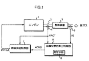
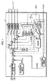
図1は本実施形態の装置の全体的システム構成を示すブロック図である。図中、1は例えば自動車あるいはハイブリッド車に車両の推進源として搭載された4気筒エンジン(内燃機関)である。このエンジン1の各気筒毎に燃料及び空気の混合気の燃焼により生成される排ガスは、エンジン1の近傍で共通の排気管2(排気通路)に集合され、この排気管2を介して大気側に放出される。
【0050】
排気管2には、例えば三元触媒により構成された排ガス浄化用の触媒装置3が介装されている。この触媒装置3は、排ガス中のHC(ハイドロカーボン)やNOx(窒素酸化物)を酸化/還元作用等により浄化する。
【0051】
また、排気管2には、触媒装置3の上流側(詳しくはエンジン1の各気筒毎の排ガスの集合箇所)で空燃比センサ4が装着され、さらに触媒装置3の下流側で排ガスセンサ5が装着されている。
【0052】
空燃比センサ4(以下、LAFセンサ4という)は、エンジン1で燃焼した混合気の空燃比、詳しくはエンジン1の各気筒毎の排ガスの集合箇所における排ガス中の酸素濃度により把握される空燃比(以下、単にエンジン1の空燃比という)の検出値を表す出力KACTを生成するものである。このLAFセンサ4は、例えば本願出願人が特開平4−369471号公報にて詳細に説明した広域空燃比センサにより構成されたものである。このLAFセンサ4の出力KACTは、排ガス中の酸素濃度に対応した空燃比の比較的広範囲にわたって、それに比例したレベルのものとなる(空燃比の変化に対して出力KACTがリニアに変化する)。
【0053】
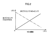
排ガスセンサ5は、本実施形態では、触媒装置3を通過した排ガス中のNOx濃度(触媒装置3によるNOxの浄化後の濃度)の検出値を表す出力VSを生成するNOxセンサである。この場合、排ガスセンサ5は、その出力VSが、図2に実線で示すように、NOx濃度の増加に伴い、それにほぼ比例して該出力VSのレベルが増加していく特性、すなわち、前述のポジティブ特性を有するものである。
【0054】
尚、NOxセンサには、図2に仮想線で示すように、NOx濃度の増加に伴い、NOxセンサの出力がリニアに減少していくネガティブ特性を有するものもあるが、本実施形態では、実線で示すポジティブ特性を有するものである。
【0055】
本実施形態の装置は、基本的には、触媒装置3によるNOxの浄化率が該触媒装置3の劣化状態等によらずに最大(極大)となるように、換言すれば、排ガスセンサ5の出力VSが表すNOx濃度(触媒装置3による浄化後のNOx濃度)が最小(極小)となるようにエンジン1の空燃比を操作する制御を行う。
【0056】
この制御を行なうために、本実施形態の装置は、前記LAFセンサ4の出力KACT及び排ガスセンサ5の出力VSのサンプリングデータを用いて排ガスセンサ5の出力VSが表すNOx濃度が最小(極小)となるようなエンジン1の目標空燃比KCMD(これはLAFセンサ4の出力KACTの目標値でもある)を逐次算出する目標空燃比算出手段としての目標空燃比算出制御器6と、この目標空燃比算出制御器6が求めた目標空燃比KCMDにLAFセンサ4の出力KACT(エンジン1の空燃比の検出値)を収束させるようにエンジン1の燃料供給量(燃料噴射量)を調整することで、エンジン1の空燃比を操作する空燃比操作手段としての燃料供給制御器7とを備えている。
【0057】
尚、目標空燃比算出制御器6は、後述する同定手段8としての機能も含んでいる。また、燃料供給制御器7には、LAFセンサ4の出力KAC Tの他、排ガスセンサ5の出力VSや、エンジン1の回転数、吸気圧(吸気管内圧)、冷却水温等を検出するための図示しない各種センサの出力も与えられるようになっている。
【0058】
これらの制御器6,7は、マイクロコンピュータを用いて構成されたもので、それぞれの制御処理を所定の制御サイクルで実行する。この場合、本実施形態では、燃料供給制御器7が実行する処理(燃料噴射量の調整処理)の制御サイクルは、エンジン1のクランク角周期(所謂TDC)に同期した周期とされている。また、目標空燃比算出制御器6が実行する目標空燃比の算出処理の制御サイクルは、あらかじ定めた一定周期(前記クランク角周期よりも長い周期)としている。
【0059】
ここで、これらの制御器6,7をさらに説明する前に、触媒装置3によるNOxの浄化特性を説明しておく。
【0060】
触媒装置3は、エンジン1の空燃比の変化に対して基本的には図3に示すようなNOxの浄化特性(NOxの浄化率の特性)を有する。図3の実線は、新品の触媒装置3に関するグラフである。また、図3の破線及び一点鎖線は、ある程度劣化が進行した触媒装置3に関するグラフである。さらに詳しくは、破線のグラフは、劣化の進行度合いが比較的小さい触媒装置3に関するもの、一点鎖線のグラフ劣化の進行度合いが比較的大きい触媒装置3に関するものである。
【0061】
図3に実線のグラフで示すように、新品の触媒装置3によるNOxの浄化率は、エンジン1の空燃比がある値AF1よりもリッチ側の空燃比域にあるときには、ほぼ一定(略100%)の最大の浄化率となる。そして、エンジン1の空燃比が上記の値AF1よりもリーン側の空燃比域になると、NOxの浄化率が急激に低下する。
【0062】
また、触媒装置3の劣化がある程度進行すると、図3の破線や一点鎖線のグラフで示すように、NOxの浄化率は、ある値AF2(:破線),AF3(:一点鎖線)の空燃比において極大値をもつ(ピークをもつ)。そして、エンジン1の空燃比がNOxの浄化率の極大値に対応する値AF2,AF3から、リッチ側及びリーン側のいずれに変化しても、NOxの浄化率が減少していく。この場合、NOxの浄化率の極大値からの減少は、リーン側では比較的急激に生じ(グラフの傾きが大きい)、リッチ側では、比較的緩やかに生じる(グラフの傾きが小さい)。尚、触媒装置3が劣化した状態におけるNOxの浄化率の極大値は、触媒装置3の新品状態における浄化率の最大値よりも小さい。また、該極大値は、触媒装置3の劣化の進行に伴い小さくなる。
【0063】
このように触媒装置3によるNOxの浄化率は、触媒装置3の新品状態を除いて、エンジン1の空燃比の変化に対して基本的には極大値を持つような特性を呈する。
【0064】
尚、触媒装置3の新品状態を含めた該触媒装置3の各劣化状態において、NOxの浄化率が最大(極大)となるような空燃比の値(前記AF1,AF2,AF3等)は、該触媒装置3が浄化するNOxの他の成分、例えばHCの浄化率(これについては後述の他の実施形態で説明する)も概ね最大となるような空燃比である。そして、そのような空燃比の値(AF1,AF2,AF3等)は、基本的には触媒装置3の劣化が進行するに伴い、リーン側にシフトする。さらにそのような空燃比の値(AF1,AF2,AF3等)の付近におけるNOxの浄化率の変化は、基本的には、触媒装置3の劣化が進行するに伴い、急峻になる(浄化率のグラフの凸形状がより先鋭になる)。
【0065】
このような触媒装置3の浄化特性を考慮し、エンジン1の空燃比の変化に対する前記排ガスセンサ5(NOxセンサ)の出力VSの特性をさらに説明する。尚、以下の説明では、触媒装置3の浄化率や排ガスセンサ5の出力VS等の、エンジン1の空燃比に対する特性を単に対空燃比特性ということがある。
【0066】
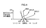
触媒装置3が上述のようなNOxの浄化特性を有するため、該触媒装置3の下流側の排ガスセンサ5(NOxセンサ)が検出するNOx濃度、すなわち、触媒装置3による浄化後の排ガス中のNOx濃度は、図4に示す如く、エンジン1の空燃比の変化に対して、基本的には、前記図3のグラフの上下を反転させたような形態の特性を呈することとなる。つまり、該NOx濃度の対空燃比特性は、触媒装置3の新品状態(図4の実線のグラフ)を除いて、基本的には、極小値を持つ特性(図4の破線又は一点鎖線のような凹形状のグラフ)となる。
【0067】
そして、本実施形態では、NOx濃度に対する前記排ガスセンサ5の出力特性は前述したポジティブ特性であるため、排ガスセンサ5の出力VSの対空燃比特性も、図4に示したNOx濃度そのものの特性と同じになる。すなわち、その特性を改めて説明すれば、排ガスセンサ5の出力VSの対空燃比特性は、触媒装置3の新品状態を除いて(触媒装置3がある程度劣化した状態)、図4の破線あるいは一点鎖線のグラフで示す如く、触媒装置3によるNOxの浄化率が極大となるようなエンジン1の空燃比(AF2,AF3等)において排ガスセンサ5の出力VSが極小値を採る特性(凹形状のグラフ特性)となる。また、触媒装置3の新品状態では、図4の実線のグラフで示す如く、ある値AF1の空燃比よりもリッチ側の空燃比域、すなわち、NOxの浄化率がほぼ一定の最大値(略100%)に維持されるような空燃比域において、排ガスセンサ5の出力VSはほぼ一定の最小レベル(略0V)に維持される。そして、エンジン1の空燃比が上記値AF1よりもリーン側の空燃比になると、排ガスセンサ5の出力VSが急激に増加していく。
【0068】
以上説明した、触媒装置3の浄化特性や排ガスセンサ5(NOxセンサ)の出力VSの対空燃比特性を考慮しつつ、前記目標空燃比算出制御器6及び燃料供給制御器7をさらに説明する。
【0069】
まず、前記目標空燃比算出制御器6は、排ガスセンサ5の出力VSあるいはその出力VSから把握されるNOx濃度(NOx濃度の検出値)が最小(極小)となるようなエンジン1の目標空燃比KCMD、換言すれば、触媒装置3によるNOxの浄化率が最大(極大)となるような目標空燃比KCMDを、次のように構築されたアルゴリズムによって算出するものである。
【0070】
すなわち、このアルゴリズムの概要を説明すれば、本実施形態では、前述のような排ガスセンサ5の出力VSの対空燃比特性を非線形関数としての二次関数により近似的に表現することとする(このことは排ガスセンサ5が検出するNOx濃度の対空燃比特性を二次関数により表現することと実質的に等価である)。そして、その二次関数のグラフ形状を規定するパラメータ、すなわち、該二次関数の各次数の項に係る係数や定数項の値を、目標空燃比算出制御器6の制御サイクル毎に、エンジン1の運転時における前記LAFセンサ4の出力KACT(エンジン1の空燃比の検出値)及び排ガスセンサ5の出力VSのサンプリングデータを用いて逐次同定する。さらに、そのパラメータの値を同定した二次関数を用いてエンジン1の目標空燃比KCMDを逐次求める。
【0071】
さらに詳説すると、本実施形態で排ガスセンサ5の出力VSの対空燃比特性を近似的に表現する前記二次関数は、エンジン1の空燃比の検出値を表すLAFセンサ4の出力KACTを独立変数、排ガスセンサ5の出力VSを従属変数とする二次関数により与えられる。そして、本実施形態では、この二次関数を数式表現するために、独立変数としてのLAFセンサ4の出力KACT(空燃比の検出値)をそのまま用いる代わりに、該出力KACTとあらかじめ定めた所定の基準値FLAF/BASE(以下、空燃比基準値FLAF/BASEという)との偏差kact(=KACT−FLAF/BASE。以下、偏差空燃比kactという)を用い、次式(1)により、該二次関数を定義しておく。尚、上記空燃比基準値FLAF/BASEは、本実施形態では例えば理論空燃比の値としている。
【0072】
【数1】

ここで、式(1)においては、この二次関数の従属変数の値である関数値(式(1)の右辺の演算結果の値)と、排ガスセンサ5の実際の出力VSの値とを区別するため、二次関数の従属変数としての排ガスセンサ5の出力の参照符号(変数記号)として、「VS」の代わりに「VSH1」を用いている。以下の説明では、この参照符号「VSH1」を付した排ガスセンサ5の出力を関数出力VSH1と称する。
【0074】
この二次関数の式(1)の二次の項「kact2」に係る係数a1と、一次の項「kact」に係る係数b1と、定数項c1とが、目標空燃比算出制御器6の同定手段8としての機能によって、その値を同定するパラメータである。そして、目標空燃比算出制御器6の同定手段8が、上記パラメータa1,b1,c1の値を同定するアルゴリズムは、次のように構築された逐次型同定アルゴリズムである。
【0075】
すなわち、この逐次型同定アルゴリズムでは、目標空燃比算出制御器6の制御サイクル毎に、LAFセンサ4の出力の現在値KACT(k)(kは制御サイクルの番数を示す。以下、同様)から前記空燃比基準値FLAF/BASEを減算してなる偏差空燃比kact(k)と、前記パラメータa1,b1,c1の同定値の現在値a1(k),b1(k),c1(k)(これは、基本的には前回の制御サイクルで求めたパラメータa1,b1 ,c1の同定値である)とを用いて次式(2)の演算を行うことで、各制御サイクルにおける排ガスセンサ5の関数出力VSH1(k)が求められる。
【0076】
【数2】
尚、式(2)中の「Θ1」、「ξ1」は、同式(2)の但し書きで定義した通りのベクトルである。そして、式(2)やその但し書きで用いている「T」は転置を意味する(以下、同様)。
【0078】
さらに、次式(3)のように、上記関数出力VSH1(k)と、現在の制御サイクルにおける排ガスセンサ5の実際の出力VS(k)との間の偏差として与えられる同定誤差ID/E1(k)が求められる。
【0079】
【数3】
目標空燃比算出制御器6の同定手段8が実行する逐次型同定アルゴリズムは、上記同定誤差ID/E1を最小にするように、前記パラメータa1,b1,c1の新たな同定値a1(k+1),b1(k+1),c1(k+1)、換言すれば、これらの同定値を成分とする新たな前記ベクトルΘ1(k+1)(以下、同定パラメータベクトルΘ1という)を求めるものである。そして、この新たな同定パラメータベクトルΘ1(k+1)の算出、すなわち、パラメータa1,b1,c1の同定値の更新は、次式(4)により行なわれる。
【0081】
【数4】
すなわち、パラメータa1,b1,c1の現在の同定値a1(k),b1(k),c1(k)(前回の制御サイクルで求められた同定値)を、今回の制御サイクルにおける同定誤差ID/E1(k)に比例させた量だけ変化させることで、パラメータa1,b1,c1の新たな同定値a1(k+1),b1(k+1),c1(k+1)が求められる。
【0083】
ここで、式(4)中の「Kp1(k)」は、制御サイクル毎に次式(5)により決定される三次のベクトルで、各パラメータa1,b1,c1の同定値の同定誤差ID/E1に応じた変化度合い(ゲイン)を規定するものである。
【0084】
【数5】
また、式(5)中の「P1(k)」は、制御サイクル毎に次式(6)の漸化式により更新される三次の正方行列である。
【0086】
【数6】
尚、式(6)の行列P1(k)の初期値P1(0)は、その各対角成分を正の数とした対角行列である。また、式(6)中の「λ1」、「λ2」は0<λ1≦1及び0≦λ2<2の条件を満たすように設定される。
【0088】
この場合、上記λ1,λ2の設定の仕方によって、逐次型最小ニ乗法、逐次型重み付き最小二乗法、固定ゲイン法、漸減ゲイン法等、各種の具体的な同定アルゴリズムが定まる。いずれの手法を用いてもよいが、本実施形態では、例えば逐次型最小二乗法(この場合、λ1=λ2=1)の同定アルゴリズムを採用している。
【0089】
以上説明したアルゴリズムが、本実施形態で二次関数のパラメータa1,b1,c1の値を同定するための逐次型同定アルゴリズムの内容である。
【0090】
尚、本実施形態では、パラメータa1,b1,c1の値の同定に際して、特に二次関数の二次の項の係数であるパラメータa1の同定値を制限する等の付加的な処理も行なうのであるが、これらについては後述する。
【0091】
目標空燃比算出制御器6は、上述のようにしてパラメータa1, b1,c1の値を同定した二次関数を用いて、次のように、エンジン1の目標空燃比KCMD(LAFセンサ4が検出する空燃比の目標値)を制御サイクル毎に求める。
【0092】
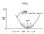
すなわち、上記のように二次関数のパラメータa1,b1,c1の値を同定したとき、その同定値により定まる二次関数のグラフ形状は、排ガスセンサ5の出力VSの対空燃比特性のグラフ形状を近似するものとなる。このとき、排ガスセンサ5の出力VSの対空燃比特性は、前述のように、基本的には極小値を有する特性(グラフ形状が凹形状となる特性)であるので、パラメータa1,b1, c1の同定値により定まる二次関数のグラフ形状も基本的には極小値をもつ凹形状となる。
【0093】
例えば、触媒装置3のある劣化状態において、排ガスセンサ5の出力VSと、LAFセンサ4による偏差空燃比kact(=KACT−FLAF/BASE)とのサンプリングデータは、図5に点描部分で示すような傾向で得られ、このとき、パラメータa1,b1,c1の同定値により定まる二次関数のグラフは、同図5に実線で示すような凹形状のものとなる。
【0094】
また、本実施形態では、前述の如く、排ガスセンサ5の出力VSが極小となるようなエンジン1の空燃比(これは排ガスセンサ5の出力VSから把握されるNOx濃度自体が極小となるような空燃比である)を目標空燃比KCMDとして求める。
【0095】
そこで、目標空燃比算出制御器6は、基本的には、前記二次関数の関数値(前記関数出力VSH1)が極小値となるような偏差空燃比kactの値(図5の点Aにおける偏差空燃比kactの値)を、LAFセンサ4が検出する空燃比と前記空燃比基準値FLAF/BASEとの偏差の目標値、すなわち目標空燃比KCMDと空燃比基準値FLAF/BASEとの偏差(=KCMD−FLAF/BASE。以下、目標偏差空燃比kcmdという)として求める。
【0096】
この目標偏差空燃比kcmdは、該二次関数のパラメータa1,b1,c1のうちの、パラメータa1,b1の同定値(詳しくは最新の同定値a1(k+1),b1(k+1))を用いて次式(7)により求めることができる。
【0097】
【数7】
そして、目標空燃比算出制御器6は、基本的には、この式(7)により得られる目標偏差空燃比kcmdに前記空燃比基準値FLAF/BASEを加算することで、制御サイクル毎の目標空燃比KCMDを決定する。
【0099】
ところで、前述したように、触媒装置3の新品状態では、排ガスセンサ5の出力VSの対空燃比特性は極小値をもたない。このような場合、排ガスセンサ5の出力VSと、LAFセンサ4による偏差空燃比kact(=KACT−FLAF/BASE)とのサンンプリングデータは例えば図6に点描部分で示すような傾向で得られ、このとき、パラメータa1,b1,c1の同定値により定まる二次関数のグラフは、同図6に実線で示すようなものとなる。
【0100】
このような場合、仮に、二次関数の関数値の極小値に対応する偏差空燃比kactの値を目標偏差空燃比kcmdとして求めると、この目標偏差空燃比kcmdに、空燃比基準値FLAF/BASEを加算してなる目標空燃比KCMDは、排ガスセンサ5の出力VSがほぼ一定に維持される空燃比域、すなわち、触媒装置3によるNOxの浄化率がほぼ一定の最大値(略100%)に維持される空燃比域内の値となる。
【0101】
このとき、このような値の目標空燃比KCMDは、NOxの浄化性能を確保する上では支障はないが、一般に触媒装置3による他のガス成分の浄化率が低下する。例えば、新品状態の触媒装置3によるHCの浄化率は、詳細は後述の他の実施形態で説明するが、前記図3に示した空燃比の値AF1にほぼ等しい値よりもリーン側の空燃比域ではほぼ一定の最大浄化率となる。そして、当該値よりもリッチ側の空燃比域では、浄化率が低下する。
【0102】
また、上記のように触媒装置3が新品状態であって、排ガスセンサ5の出力VSの対空燃比特性が極小値を持たないような場合に、パラメータa1,b1,c1の同定値により定まる二次関数においては、その極小値は、図6に示した如く、排ガスセンサ5の実際の出力VSが採り得ない負の値(NOx濃度が略「0」のときの排ガスセンサ5の出力VSよりも小さい値)となる。
【0103】
このようなことから、本実施形態では、目標空燃比算出制御器6は、パラメータa1,b1,c1の同定値により定まる二次関数の極小値が負の値となるような場合には、該二次関数の関数値(排ガスセンサ5の関数出力VSH1)が「0」となるような偏差空燃比kactの値(この値は二つある)のうち、リーン側の値(図6の点Bにおける偏差空燃比kactの値)を、目標偏差空燃比kcmdとして求める。
【0104】
この場合、二次関数の極小値が負の値となるのは、パラメータa1,b1,c1の同定値が、b12−4・a1・c1>0という不等式を満たす場合である。また、この場合の目標偏差空燃比kcmdは、各パラメータa1,b1,c1の同定値(詳しくは、最新の同定値a1(k+1),b1(k+1),c1(k+1))を用いて、次式(8)により求められる。
【0105】
【数8】
そして、該二次関数の極小値が、「0」もしくは正の値となるような場合に、前述のように、該二次関数の極小値に対応する偏差空燃比kactの値を目標偏差空燃比kcmdとして求める。
【0107】
つまり、本実施形態では、目標空燃比算出制御器6は、制御サイクル毎に、その同定手段8により前述の如く求めた二次関数のパラメータa1,b1,c1の同定値a1(k+1),b1(k+1), c1(k+1)により定まる判別式(b12−4・a1・c1)の値に応じて、次式(9)により、目標偏差空燃比kcmd(k)を求める。
【0108】
【数9】
そして、この式(9)に従って求めた目標偏差空燃比kcmd(k)に、次式(10)のうように空燃比基準値FLAF/BASEを加算することで、制御サイクル毎の目標空燃比KCDM(k)を決定する。
【0110】
【数10】
以上説明した処理が、目標空燃比算出制御器6の基本的処理である。
【0112】
次に、前記燃料供給制御器7をさらに説明する。
【0113】
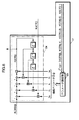
燃料供給制御器7は、図7に示すように、その機能的構成として、エンジン1の基本燃料噴射量Timを求める基本燃料噴射量算出部10と、基本燃料噴射量Timを補正するための第1補正係数KTOTAL及び第2補正係数KCMDMをそれぞれ求める第1補正係数算出部11及び第2補正係数算出部12とを具備する。
【0114】
前記基本燃料噴射量算出部10は、エンジン1の回転数NEと吸気圧PBとから、それらに応じたエンジン1の基準の燃料噴射量(燃料供給量)をあらかじめ設定されたマップを用いて求め、その基準の燃料噴射量をエンジン1の図示しないスロットル弁の有効開口面積に応じて補正することで基本燃料噴射量Timを算出するものである。
【0115】
また、第1補正係数算出部11が求める第1補正係数KTOTALは、エンジン1の排気還流率(エンジン1の吸入空気中に含まれる排ガスの割合)や、エンジン1の図示しないキャニスタのパージ時にエンジン1に供給される燃料のパージ量、エンジン1の冷却水温、吸気温等を考慮して前記基本燃料噴射量Timを補正するためのものである。
【0116】
また、第2補正係数算出部12が求める第2補正係数KCMDMは、前記目標空燃比算出制御器6が生成した目標空燃比KCMDに対応してエンジン1へ流入する燃料の冷却効果による吸入空気の充填効率を考慮して基本燃料噴射量Timを補正するためのものである。
【0117】
これらの第1補正係数KTOTAL及び第2補正係数KCMDMによる基本燃料噴射量Timの補正は、第1補正係数KTOTAL及び第2補正係数KCMDMを基本燃料噴射量Timに乗算することで行われ、この補正によりエンジン1の要求燃料噴射量Tcylが得られる。
【0118】
尚、基本燃料噴射量Timや、第1補正係数KTOTAL、第2補正係数KCMDMのより具体的な算出手法は、特開平5−79374号公報等に本願出願人が開示しているので、ここでは詳細な説明を省略する。
【0119】
燃料供給制御器7は、上記の機能的構成の他、さらに、目標空燃比算出制御器6が逐次生成する目標空燃比KCMDにLAFセンサ4の出力KACT(エンジン1の空燃比の検出値)を収束させるように、フィードバック制御により3に対する燃料噴射量を調整するフィードバック制御部13を具備している。
【0120】
このフィードバック制御部13は、本実施形態では、エンジン1の各気筒の全体的な空燃比を制御する大局的フィードバック制御部14と、エンジン1の各気筒毎の空燃比を制御する局所的フィードバック制御部15とに分別される。
【0121】
前記大局的フィードバック制御部14は、LAFセンサ4の出力KACTを前記目標空燃比KCMDに収束させるように前記要求燃料噴射量Tcylを補正する(要求燃料噴射量Tcylに乗算する)フィードバック補正係数KFBを逐次求めるものである。
【0122】
この大局的フィードバック制御部14は、LAFセンサ4の出力KACTと目標空燃比KCMDとの偏差に応じて周知のPID制御を用いて前記フィードバック補正係数KFBとしてのフィードバック操作量KLAFを生成するPID制御器16と、LAFセンサ4の出力KACTと目標空燃比KCMDとからエンジン1の運転状態の変化や特性変化等を考慮して前記フィードバック補正係数KFBを規定するフィードバック操作量KSTRを適応的に求める適応制御器17(図ではSTRと称している)とをそれぞれ独立的に具備している。
【0123】
ここで、本実施形態では、前記PID制御器16が生成するフィードバック操作量KLAFは、LAFセンサ4の出力KACT(エンジン1の空燃比の検出値)が目標空燃比KCMDに一致している状態で「1」となり、該操作量KLAFをそのまま前記フィードバック補正係数KFBとして使用できるようになっている。一方、適応制御器17が生成するフィードバック操作量KSTRはLAFセンサ4の出力KACTが目標空燃比KCMDに一致する状態で「目標空燃比KCMD」となるものである。このため、該フィードバック操作量KSTRを除算処理部18で目標空燃比KCMDにより除算してなるフィードバック操作量kstr(=KSTR/KCMD)が前記フィードバック補正係数KFBとして使用できるようになっている。
【0124】
そして、大局的フィードバック制御部14は、PID制御器16により生成されるフィードバック操作量KLAFと、適応制御器17が生成するフィードバック操作量KSTRを目標空燃比KCMDにより除算してなるフィードバック操作量kstrとを切換部19で適宜、択一的に選択する。さらに、その選択したいずれか一方のフィードバック操作量KLAF又はkstrを前記フィードバック補正係数KFBとして使用し、該補正係数KFBを前記要求燃料噴射量Tcylに乗算することにより該要求燃料噴射量Tcylを補正する。尚、かかる大局的フィードバック制御部14(特に適応制御器17)については後にさらに詳細に説明する。
【0125】
前記局所的フィードバック制御部15は、LAFセンサ4の出力KACTからエンジン1の各気筒毎の実空燃比#nA/F(n=1,2,3,4)を推定するオブザーバ20と、このオブザーバ20により推定された各気筒毎の実空燃比#nA/Fから各気筒毎の空燃比のばらつきを解消するよう、PID制御を用いて各気筒毎の燃料噴射量のフィードバック補正係数#nKLAFをそれぞれ求める複数(気筒数個)のPID制御器21とを具備する。
【0126】
ここで、オブザーバ21は、それを簡単に説明すると、各気筒毎の実空燃比#nA/Fの推定を次のように行うものである。すなわち、エンジン1からLAFセンサ4の箇所(各気筒毎の排ガスの集合部)にかけての系を、エンジン1の各気筒毎の実空燃比#nA/FからLAFセンサ4が検出する空燃比を生成する系と考え、これを、LAFセンサ4の検出応答遅れ(例えば一次遅れ)や、LAFセンサ4が検出する空燃比に対するエンジン1の各気筒毎の空燃比の時間的寄与度を考慮してモデル化する。そして、そのモデルの基で、LAFセンサ4の出力KACTから、逆算的に各気筒毎の実空燃比#nA/Fを推定する。
【0127】
尚、この種のオブザーバ21は、本願出願人が例えば特開平7−83094号公報にて詳細に説明しているので、ここでは、さらなる説明を省略する。
【0128】
また、局所的フィードバック制御部15の各PID制御器21は、LAFセンサ4の出力KACTを、燃料供給制御器7における前回の制御サイクルで各PID制御器21により求められたフィードバック補正係数#nKLAFの全気筒についての平均値により除算してなる値を各気筒の空燃比の目標値とする。そして、その目標値とオブザーバ21により求められた各気筒毎の実空燃比#nA/Fの推定値との偏差が解消するように、今回の制御サイクルにおける各気筒毎のフィードバック補正係数#nKLAFを求める。
【0129】
さらに、局所的フィードバック制御部15は、前記要求燃料噴射量Tcylに大局的フィードバック制御部14のフィードバック補正係数KFBを乗算してなる値に、各気筒毎のフィードバック補正係数#nKLAFを乗算することで、各気筒の出力燃料噴射量#nTout(n=1,2,3,4)を求める。
【0130】
このようにして求められる各気筒の出力燃料噴射量#nToutは、燃料供給制御器7に備えた各気筒毎の付着補正部22により吸気管の壁面付着を考慮した補正が各気筒毎になされた後、各気筒に対する燃料噴射量の指令値として、エンジン1の図示しない燃料噴射装置に与えられる。そして、その付着補正がなされた出力燃料噴射量#nTout(燃料噴射量の指令値)に従って、気筒群4の各気筒への燃料噴射が行われるようになっている。
【0131】
尚、上記付着補正については、本願出願人が例えば特開平8−21273号公報にて詳細に説明しているので、ここではさらなる説明を省略する。
【0132】
前記大局的フィードバック制御部14、特に前記適応制御器17をさらに説明する。
【0133】
前記大局的フィードバック制御部14は、前述のようにLAFセンサ4の出力KACT(エンジン1の空燃比の検出値)を目標空燃比KCMDに収束させるようにフィードバック制御を行うものである。このとき、このようなフィードバック制御を周知のPID制御だけで行うようにすると、エンジン1の運転状態の変化や経年的特性変化等、動的な挙動変化に対して、安定した制御性を確保することが困難である。
【0134】
前記適応制御器17は、上記のようなエンジン1の動的な挙動変化を補償したフィードバック制御を可能とする漸化式形式の制御器であり、I.D.ランダウ等により提唱されているパラメータ調整則を用いて、図8に示すように、複数の適応パラメータを設定するパラメータ調整部23と、設定された適応パラメータを用いて前記フィードバック操作量KSTRを算出する操作量算出部24とにより構成されている。
【0135】
ここで、パラメータ調整部23について説明すると、ランダウ等の調整則では、離散系の制御対象の伝達関数B(Z-1)/A(Z-1)の分母分子の多項式を一般的に下記の式(11),(12)のようにおいたとき、パラメータ調整部23が設定する適応パラメータθハット(j)(jは制御サイクルの番数を示す)は、式(13)のようにベクトル(転置ベクトル)で表される。また、パラメータ調整部23への入力ζ(j)は、式(14)のように表される。この場合、本実施形態では、大局的フィードバック制御部14の制御対象であるエンジン1が一次系で3制御サイクル分の無駄時間dp(エンジン1の燃焼サイクルの3サイクル分の時間)を持つプラントと考え、式(11)〜式(14)でm=n=1,dp=3とし、設定する適応パラメータはs0,r1,r2,r3,b0の5個とした(図8参照)。尚、式(14)の上段式及び中段式におけるus,ysは、それぞれ、制御対象への入力(操作量)及び制御対象の出力(制御量)を一般的に表したものであるが、本実施形態では、上記入力をフィードバック操作量KSTR、制御対象(エンジン1)の出力を前記LAFセンサ4の出力KACT(空燃比の検出値)とし、パラメータ調整部23への入力ζ(j)を、式(14)の下段式により表す(図8参照)。
【0136】
【数11】
【数12】
【数13】
【数14】
ここで、前記式(13)に示される適応パラメータθハットは、適応制御器17のゲインを決定するスカラ量要素b0ハット-1(Z-1,j)、操作量を用いて表現される制御要素BRハット(Z-1,j)、及び制御量を用いて表現される制御要素S(Z- 1,j)からなり、それぞれ、次式(15)〜(17)により表現される(図8の操作量算出部24のブロック図を参照)。
【0141】
【数15】
【数16】
【数17】
パラメータ調整部23は、これらのスカラ量要素や制御要素の各係数を設定して、それを式(13)に示す適応パラメータθハットとして操作量算出部24に与えるもので、現在から過去に渡るフィードバック操作量KSTRの時系列データとLAFセンサ4の出力KACTとを用いて、該出力KACTが前記目標空燃比KCMDに一致するように、適応パラメータθハットを算出する。
【0145】
この場合、具体的には、適応パラメータθハットは、次式(18)により算出する。
【0146】
【数18】
同式(18)において、Γ(j)は、適応パラメータθハットの設定速度を決定するゲイン行列(この行列の次数はm+n+dp)、eアスタリスク(j)は、適応パラメータθハットの推定誤差を示すもので、それぞれ次式(19),(20)のような漸化式で表される。
【0148】
【数19】
【数20】
ここで、式(20)中の「D(Z-1)」は、収束性を調整するための、漸近安定な多項式であり、本実施形態ではD(Z-1)=1としている。
【0151】
尚、式(19)のλ1(j),λ2(j)の選び方により、漸減ゲインアルゴリズム、可変ゲインアルゴリズム、固定トレースアルゴリズム、固定ゲインアルゴリズム等の種々の具体的なアルゴリズムが得られる。エンジン1の燃料噴射あるいは空燃比等の時変プラントでは、漸減ゲインアルゴリズム、可変ゲインアルゴリズム、固定ゲインアルゴリズム、および固定トレースアルゴリズムのいずれもが適している。
【0152】
前述のようにパラメータ調整部23により設定される適応パラメータθハット(s0,r1,r2,r3,b0)と、前記目標空燃比KCMDとを用いて、操作量算出部24は、次式(21)の漸化式により、フィードバック操作量KSTRを求める。図8の操作量算出部24は、同式(21)の演算をブロック図で表したものである。
【0153】
【数21】
尚、式(21)により求められるフィードバック操作量KSTRは、LAFセンサ4の出力KACTが目標空燃比KCMDに一致する状態において、「目標空燃比KCMD」となる。このために、前述の如く、フィードバック操作量KSTRを除算処理部18によって目標空燃比KCMDで除算することで、前記フィードバック補正係数KFBとして使用できるフィードバック操作量k strを求めるようにしている。
【0155】
このように構築された適応制御器17は、前述したことから明らかなように、制御対象であるエンジン1の動的な挙動変化を考慮した漸化式形式の制御器であり、換言すれば、エンジン1の動的な挙動変化を補償するために、漸化式形式で記述された制御器である。そして、より詳しくは、漸化式形式の適応パラメータ調整機構を備えた制御器と定義することができる。
【0156】
尚、この種の漸化式形式の制御器は、所謂、最適レギュレータを用いて構築する場合もあるが、この場合には、一般にはパラメータ調整機構は備えられておらず、エンジン1の動的な挙動変化を補償する上では、前述のように構成された適応制御器17が好適である。
【0157】
以上が適応制御器17の詳細である。
【0158】
尚、適応制御器17と共に、大局的フィードバック制御部14に具備したPID制御器16は、一般のPID制御と同様に、LAFセン4の出力KACTと、目標空燃比KCMDとの偏差から、比例項(P項)、積分項(I項)及び微分項(D項)を算出し、それらの各項の総和をフィードバック操作量KLAFとして算出する。この場合、本実施形態では、積分項(I項)の初期値を「1」とすることで、LAFセンサ4の出力KACTが目標空燃比KCMDに一致する状態において、フィードバック操作量KLAFが「1」になるようにし、該フィードバック操作量KLAFをそのまま燃料噴射量を補正するための前記フィードバック補正係数KFBとして使用することができるようしている。また、比例項、積分項及び微分項のゲインは、エンジン1の回転数と吸気圧とから、あらかじめ定められたマップを用いて決定される。
【0159】
また、大局的フィードバック制御部14の前記切換部19は、エンジン1の冷却水温の低温時や、高速回転運転時、吸気圧の低圧時等、エンジン1の燃焼が不安定なものとなりやすい場合、あるいは、目標空燃比KCMDの変化が大きい時や、空燃比のフィードバック制御の開始直後等、これに応じたLAFセンサ4の出力KACTが、そのLAFセンサ4の応答遅れ等によって、信頼性に欠ける場合、あるいは、エンジン1のアイドル運転時のようエンジン1の運転状態が極めて安定していて、適応制御器17による高ゲイン制御を必要としない場合には、PID制御器16により求められるフィードバック操作量KLAFを燃料噴射量を補正するためのフィードバック補正量数KFBとして出力する。そして、上記のような場合以外の状態で、適応制御器17により求められるフィードバック操作量KSTRを目標空燃比KCMDで除算してなるフィードバック操作量kstrを燃料噴射量を補正するためのフィードバック補正係数KFBとして出力する。これは、適応制御器17が、高ゲイン制御で、LAFセンサ4の出力KACTを急速に目標空燃比KCMDに収束させるように機能するため、上記のようにエンジン1の燃焼が不安定となったり、LAFセンサ4の出力KACTの信頼性に欠ける等の場合に、適応制御器17のフィードバック操作量KSTRを用いると、かえって空燃比の制御が不安定なものとなる虞れがあるからである。
【0160】
このような切換部19の作動は、例えば特開平8−105345号公報にて本願出願人が詳細に説明しているので、ここでは、さらなる説明を省略する。
【0161】
次に、本実施形態のシステムの全体の作動を詳細に説明する。
【0162】
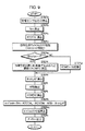
まず、図9及び図10のフローチャートを参照して、前記燃料供給制御器7によるエンジン1の燃料噴射量の制御処理について説明する。燃料供給制御器7は、この処理をエンジン1のクランク角周期(TDC)と同期した制御サイクルで次のように行なう。
【0163】
燃料供給制御器7は、まず、エンジン1の回転数NE、吸気圧PB等を検出する図示しないセンサや、LAFセンサ4、排ガスセンサ5等、各種センサの出力を読み込む(STEPa)。
【0164】
次いで、基本燃料噴射量算出部10によって、前述の如くエンジン1の回転数NE及び吸気圧PBに対応する燃料噴射量をスロットル弁の有効開口面積に応じて補正してなる基本燃料噴射量Timが求められる(STEPb)。さらに、第1補正係数算出部11によって、エンジン1の冷却水温やキャニスタのパージ量等に応じた第1補正係数KTOTALが算出される(STEPc)。
【0165】
次いで、燃料供給制御器7は、前記目標空燃比算出制御器6が求める目標空燃比KCMDをエンジン1の空燃比を操作するために使用するか否か(ここでは空燃比操作のON/OFFという)の判別処理を行って、この空燃比操作のON/OFFを規定するフラグf/btc/onの値を設定する(STEPd)。このフラグf/btc/onの値は、それが「0」であるとき、目標空燃比算出制御器6が求める目標空燃比KCMDを使用しないこと(OFF)を意味し、「1」であるとき、目標空燃比算出制御器6が求める目標空燃比KCMDを使用すること(ON)を意味する。
【0166】
上記の判別処理では、図10に示すように、前記排ガスセンサ5(NOxセンサ)が活性化しているか否かの判別(STEPd−1)、並びにLAFセンサ4が活性化しているか否かの判別(STEPd−2)が行なわれる。この判別は、それらのセンサの出力電圧等に基づいて行なわれる。
【0167】
このとき、排ガスセンサ5及びLAFセンサ4のいずれかが活性化していない場合には、それらセンサ5,4の出力データ(検出データ)を精度よく得ることができないため、フラグf/btc/onの値を「0」にセットする(STEPd−10)。また、エンジン1のリーン運転中(希薄燃焼運転)であるか否か、エンジン1の始動直後の触媒装置3の早期活性化を図るためにエンジン1の点火時期が遅角側に制御されているか否か、エンジン1のスロットル弁が略全開状態であるか否か、及びエンジン1のフュエルカット中(燃料供給の停止中)であるか否かの判別が行われる(STEPd−3〜d−6)。そして、これらのいずれかの条件が成立している場合には、目標空燃比算出制御器6が求める目標空燃比KCMDを使用してエンジン1の空燃比を操作することは好ましくないか、もしくは操作することができないので、フラグf/btc/onの値を「0」にセットする(STEPd−10)。
【0168】
さらに、エンジン1の回転数NE及び吸気圧PBがそれぞれ所定範囲内(正常な範囲内)にあるか否かの判別が行なわれ(STEPd−7,d−8)、いずれかが所定範囲内に無い場合には、目標空燃比算出制御器6が算出する目標空燃比KCMDを使用してエンジン1の空燃比を操作することは好ましくないので、フラグf/btc/onの値を「0」にセットする(STEPd−10)。
【0169】
そして、STEPd−1,d−2,d−7,d−8の条件が満たされ、且つ、STEPd−3〜d−6の条件が成立していない場合に(このような場合はエンジン1の通常的な運転状態である)、目標空燃比算出制御器6が求める目標空燃比KCMDをエンジン1の空燃比の操作に使用すべく、フラグf/btc/onの値を「1」にセットする(STEPd−9)。
【0170】
図9の説明に戻って、上記のようにフラグf/btc/onの値を設定した後、燃料供給制御器7は、フラグf/btc/onの値を判断し(STEPe)、f/btc/on=1である場合には、目標空燃比算出制御器6が求めた最新の目標空燃比KCMDを読み込む(STEPf)。また、f/btc/on=0である場合には、目標空燃比KCMDを所定値に設定する(STEPg)。この場合、目標空燃比KCMDとして設定する所定値は、例えばエンジン1の回転数NEや吸気圧PBからあらかじめ定めたマップ等を用いて決定される。
【0171】
次いで、燃料供給制御器7は、前記局所的フィードバック制御部15において、前述の如くオブザーバ20によりLAFセンサ4の出力KACTから推定した各気筒毎の実空燃比#nA/Fに基づき、PID制御器21により、各気筒毎の空燃比のばらつきを解消するためのフィードバック補正係数#nKLAFを算出する(STEPh)。さらに、大局的フィードバック制御部14により、フィードバック補正係数KFBを算出する(STEPi)。
【0172】
この場合、大局的フィードバック制御部14は、前述の如く、PID制御器16により求められるフィードバック操作量KLAFと、適応制御器17により求められるフィードバック操作量KSTRを目標空燃比KCMDで除算してなるフィードバック操作量kstrとから、切換部19によってエンジン1の運転状態等に応じていずれか一方のフィードバック操作量KLAF又はkstrを選択する(通常的には適応制御器17側のフィードバック操作量kstrが選択される)。そして、それを燃料噴射量を補正するためのフィードバック補正係数KFBとして決定する。
【0173】
尚、フィードバック補正係数KFBを、PID制御器16側のフィードバック操作量KLAFから適応制御器17側のフィードバック操作量kstrに切り換える際には、該補正係数KFBの急変を回避するために、適応制御器17は、その切り換えの際の制御サイクルに限り、補正係数KFBを前回の制御サイクルにおける補正係数KFB(=KLAF)に保持するようにフィードバック操作量KS TRを求める。同様に、補正係数KFBを、適応制御器17側のフィードバック操作量kstrからPID制御器16側のフィードバック操作量KLAFに切り換える際には、PID制御器16は、自身が前回の制御サイクルで求めたフィードバック操作量KLAFが、前回の制御サイクルにおける補正係数KFB(=kstr)であったものとして、今回の制御サイクルにおけるフィードバック操作量KLAFを算出する。
【0174】
上記のようにしてフィードバック補正係数KFBを算出した後、燃料供給制御器7は、さらに、前記STEPf又はSTEPgで決定された目標空燃比KCMDに応じた前記第2補正係数KCMDMを第補正係数算出部12により算出する(STEPj)。
【0175】
次いで、燃料供給制御器7は、前述のように求められた基本燃料噴射量Timに、第1補正係数KTOTAL、第2補正係数KCMDM、フィードバック補正係数KFB、及び各気筒毎のフィードバック補正係数#nKLAFを乗算することで、各気筒毎の出力燃料噴射量#nToutを求める(STEPk)。そして、この各出力燃料噴射量#nToutが、付着補正部22によって、エンジン1の吸気管の壁面への燃料の付着を考慮した補正を施された後(STEPm)、各気筒毎の最終的な燃料噴射量の指令値として、エンジン1の図示しない燃料噴射装置に出力される(STEPn)。
【0176】
そして、エンジン1にあっては、各気筒毎の出力燃料噴射量#nToutに従って、各気筒への燃料噴射が行なわれる。
【0177】
以上のような各気筒毎の出力燃料噴射#nToutの算出及びそれに応じたエンジン1の燃料噴射がエンジン1のクランク角周期(TDC)に同期した制御サイクルで行なわれる。これにより、LAFセンサ4の出力KACT(空燃比の検出値)が、目標空燃比KCMDに収束するようにエンジン1の空燃比が操作される。この場合、特に、フィードバック補正係数KFBとして、適応制御器17側のフィードバック操作量kstrを使用している状態では、エンジン1の運転状態の変化や特性の変化等の挙動変化に対して、高い安定性を有してLAFセンサ4の出力KACTを迅速に目標空燃比KCMDに収束制御することができる。また、エンジン1が有する応答遅れの影響も適正に補償することができる。
【0178】
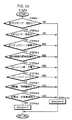
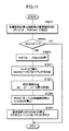
一方、前述のようなエンジン1の空燃比の操作(燃料噴射量の調整制御)と並行して、前記目標空燃比算出制御器6は、一定周期の制御サイクルで図11のフローチャートに示すメインルーチン処理を実行する。
【0179】
すなわち、目標空燃比算出制御器6は、まず、自身の演算処理(前記パラメータa1,b1,c1の同定演算や目標空燃比KCMDの算出処理)を実行するか否かの判別処理を行なって、その実行の可否をそれぞれ値「1」、「0」で示すフラグf/btc/calの値を設定する(STEP1)。また、このSTEP1では、パラメータa1,b1,c1の同定演算に関する後述の初期化を行なうか否かをそれぞれ値「1」、「0」で示すフラグf/id/resetの値も設定する。
【0180】
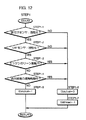
このSTEP1の処理は、図12のフローチャートに示すように行なわれる。
【0181】
すなわち、前記図9のSTEPdの場合と同様に、排ガスセンサ5及びLAFセンサ4が活性化しているか否かの判別が行なわれる(STEP1−1)。このとき、いずれかが活性化していない場合には、目標空燃比算出制御器6の演算処理に使用する排ガスセンサ5及びLAFセンサ4の検出データを精度よく取得することはできないため、フラグf/btc/calの値を「0」にセットする(STEP1−6)。
【0182】
さらにこのとき、パラメータa1,b1,c1の同定演算に関する後述の初期化を行なうために、フラグf/id/resetの値を「1」に設定する(STEP1−7)。
【0183】
また、エンジン1のリーン運転中(希薄燃焼運転)であるか否か(STEP1−3)、及びエンジン1の始動直後の触媒装置3の早期活性化を図るためにエンジン1の点火時期が遅角側に制御されているか否か(STEP1−4)の判別が行なわれる。これらのいずれかの条件が成立している場合には、目標空燃比算出制御器6が算出する目標空燃比KCDMを前記燃料供給制御器7がエンジン1の燃料制御に使用することはないので、前記STEP1−6,1−7の処理が実行され、フラグf/btc/cal及びf/id/resetの値がそれぞれ「0」、「1」にセットされる。
【0184】
そして、STEP1−1,1−2の条件が満たされ、且つSTEP1−3,1−4の条件が成立していない場合には、フラグf/btc/calの値を「1」にセットする(STEP1−5)。
【0185】
尚、このようにフラグf/btc/calの値を設定することで、目標空燃比算出制御器6が算出する目標空燃比KCMDを燃料供給制御器7が使用しない状況(図10を参照)であっても、例えばエンジン1のフュエルカット中やスロットル弁の全開時には、フラグf/btc/calの値が「1」に設定される。従って、エンジン1のフュエルカット中やスロットル弁の全開時には、目標空燃比算出制御器6は目標空燃比KCMDの算出処理を行なうこととなる。これは、このようなエンジン1の運転状況は基本的には一時的なものであるからである。
【0186】
図11の説明に戻って、上記のような判別処理を行なった後、目標空燃比算出制御器6は、次に、STEP1で設定したフラグf/btc/calの値を判断する(STEP2)。このとき、f/btc/cal=0である場合には、目標空燃比KCMDの算出等を行なうことなく、直ちに今回の制御サイクルの処理を終了する。
【0187】
一方、STEP2の判断で、f/btc/cal=1である場合には、LAFセンサ4の出力KACTの現在値KACT(k)のデータと排ガスセンサ5の出力VSの現在値VS(k)のデータとをそれぞれのセンサから取得する(STEP3)。
【0188】
さらに目標空燃比算出制御器6は、STEP3で取得したLAFセンサ4の出力KACT(k)から、前記空燃比基準値F/LAF/BASEを減算することで、偏差出力kact(k)を求める(STEP4)。
【0189】
次いで、目標空燃比算出制御器6は、その同定手段8としての機能によって、前記パラメータa1,b1,c1の同定演算に関する処理を実行する(STEP5)。
【0190】
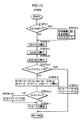
この処理は、図13のフローチャートに示すように行なわれる。
【0191】
すなわち、目標空燃比算出制御器6は、まず、前記フラグf/id/resetの値を判断する(STEP5−1)。このとき、f/id/reset=である場合には、同定演算に関する初期化を行なう(STEP5−2)。この初期化では、前記パラメータa1,b1,c1の同定値の各値があらかじめ定めた初期値に設定される(前記同定パラメータベクトルΘ1が初期化される)。また前記式(6)の行列P1(対角行列)の各成分があらかじめ定めた初期値に設定される。さらに、フラグf/id/resetの値は「0」にリセットされる。
【0192】
次いで、目標空燃比算出制御器6は、パラメータa1,b1,c1の現在値a1(k),b1(k),c1(k)(これは基本的には、前回の制御サイクルで求められた同定値である)と、前記STEP4で求めたLAFセンサ4の偏差出力kactの現在値kact(k)とを用いて前記式(2)の演算を行うことで、排ガスセンサ5の関数出力VSH1(k)を求める(STEP5−3)。
【0193】
さらに目標空燃比算出制御器6は、パラメータa1,b1,c1の新たな同定値を求めるために使用する前記ベクトルKp1(k)と前記同定誤差ID/E1(k)とをそれぞれ算出する(STEP5−4,5−5)。
【0194】
この場合、同定誤差ID/E(k)は、前記STEP3で取得した排ガスセンサ5の現在の出力VS(k)とSTEP5−3で求めた関数出力VSH1(k)とから前記式(3)に従って算出される。また、ベクトルKp1(k)は、LAFセンサ4の現在の偏差出力kact(k)を用いて前記式(2)の但し書きに従って定義されるベクトルξ1(k)と、前記行列P1の現在値P1(k)(これは基本的には、前回の制御サイクルで最終的に決定される行列Pである)とから、前記式(5)の演算により算出される。
【0195】
次いで、目標空燃比算出制御器6は、エンジン1のフュエルカット中であるか否かを判断する(STEP5−6)。このとき、フュエルカット中である場合には、パラメータa1,b1,c1の値を同定する上で適正なLAFセンサ4の出力KACTや排ガスセンサ5の出力VSを得ることができないので、前記同定パラメータベクトルΘ1を現在値に保持する(パラメータa1,b1,c1の新たな同定値a1(k+1),b1(k+1),c1(k+1)を現在値a1(k),b1(k),c1(k)に維持する)と共に、前記行列P1を現在値に保持する(STEP5−7)。そして、STEP5の処理を終了し、図11の処理に復帰する。
【0196】
一方、STEP5−6でフュエルカット中でない場合には、前記STEP5−4,5−5で求めたベクトルKp1(k)及び同定誤差ID/E1(k)を用いて、前記式(4)に従って同定パラメータベクトルΘ1を更新することで、パラメータa1,b1,c1の新たな同定値a1(k+1),b1(k+1),c1(k+1)を求める(STEP5−8)。
【0197】
次いで、目標空燃比算出制御器6は、パラメータa1の新たな同定値a1(k+1)の値が正の値であるか否かを判断する(STEP5−9)。
【0198】
このとき、前記二次関数により表現する排ガスセンサ5の出力VSの対空燃比特性は、前述のように基本的には極小値をもつため、その二次関数の二次の項に係る係数であるパラメータa1の同定値a1(k+1)は、正の値でなければならない。また、外乱等の影響により、該同定値a1(k+1)が誤って負の値になると、この同定値a1(k+1)を二次の項の係数とした二次関数は極小値ではなく、極大値をもつものとなってしまう。そして、このような二次関数を用いても、触媒装置3によるNOxの浄化率を最大化(極大化)するための目標空燃比KCMDを適正に求めることはできない。
【0199】
このため、本実施形態では、STEP5−9の判断で、a1(k+1)≦0となっていた場合には、パラメータa1の最新の同定値a1(k+1)の値を、あらかじめ十分に小さい正の値(例えば0.01)に定めた所定値ε1に強制的に設定しなおす(STEP5−10)。これにより、パラメータa1の同定値は、二次関数の関数値である関数出力VSH1や該関数出力VSH1に対応するNOx濃度が極小値をもつような正の値に制限される。尚、STEP5−9の判断で、a1(k+1)>0であった場合には、パラメータa1の最新の同定値a1(k+1)はそのままに維持される。
【0200】
このようなパラメータa1の同定値a1(k+1)の制限処理を行なった後、目標空燃比算出制御器6は、次回の制御サイクルにおける演算処理のために、前記行列P1を前記式(6)に従って更新する(STEP5−11)。そして、STEP5の処理を終了し、図11の処理に復帰する。
【0201】
図11の説明に戻って、上述のように二次関数のパラメータa1,b1,c1の値の同定に関する演算処理を行なった後、目標空燃比算出制御器6は、パラメータa1,b1,c1の最新の同定値a1(k+1),b1(k+1),c1(k+1)から、前記式(9)に従って、今回の制御サイクルにおける目標偏差空燃比kcmd(k)を算出する(STEP6)。
【0202】
すなわち、最新の同定値a1(k+1),b1(k+1),c1(k+1)により定まる判別式(b12−4・a1・c1)が「0」以下である場合(通常の場合)には、式(9)の上段側の式に従って目標偏差空燃比kcmd(k)を算出する。また、上記判別式(b12−4・a1・c1)の値が「0」よりも大きい正の値である場合(触媒装置3の新品状態に対応する場合)には、式(9)の下段側の式に従って目標偏差空燃比kcmd(k)を算出する。
【0203】
次いで、目標空燃比算出制御器6は、この目標偏差空燃比kcmd(k)に、前記空燃比基準値FLAF/BASEを加算することで、今回の制御サイクルにおける目標空燃比KCMD(k)を決定する(STEP7)。
【0204】
このようにして求められた目標空燃比KC MD(k)は図示しなメモリに時系列的に記憶保持される。そして、前記燃焼供給制御器7がその目標空燃比KCMD(k)を使用してエンジン1の空燃比を前述のように操作する場合にあっては、該燃料供給制御器7の制御サイクル毎に目標空燃比KCMD(k)の時系列データの中から、最新のものが選択される。
【0205】
尚、前述のように二次関数のパラメータa1の同定値a1(k+1)を強制的に正の値ε1に制限した場合(STEP5−10の処理を行った場合)において、そのパラメータa1の値とパラメータb1の同定値b1(k+1)とを用いて前記STEP6で算出される目標偏差空燃比kcmdは、本来あるべき目標偏差空燃比(触媒装置3の下流側のNOx濃度が極小となるような目標偏差空燃比)に対して誤差を生じている可能性がある。しかるに、前記同定手段8の逐次型同定アルゴリズムによれば、パラメータa1の同定値を正の値ε1に制限した後の制御サイクルにおいて、基本的には、速やかにパラメータa1の同定値が正の値となるようなパラメータa1,b1,c1の同定値の組を適正に得ることができる。また、二次関数のパラメータa1の同定値が負の値となるような状況は、基本的には、触媒装置3の新品状態で生じやすい。そして、このような触媒装置3の新品状態では、触媒装置3によるNOxの浄化率は、エンジン1の空燃比の広い範囲にわたって高いため、パラメータa1の同定値の強制的な制限の際に生じる目標偏差空燃比kcmdの誤差は、実用上、問題とならない。
【0206】
以上説明した内容が本実施形態の装置の作動の詳細である。
【0207】
このような本実施形態の装置によれば、排ガスセンサ5(NOxセンサ)の出力VSの対空燃比特性(これは排ガスセンサ5が検出するNOx濃度の対空燃比特性でもある)を近似する二次関数のパラメータa1, b1,c1が排ガスセンサ5の実際の出力VSとLAFセンサ4の実際の出力KACT(エンジン1の実際の空燃比の検出値)とを用いて、逐次型同定アルゴリズム(本実施形態では逐次型最小二乗法のアルゴリズム)により目標空燃比算出制御器6の制御サイクル毎に逐次同定される。
【0208】
このため、二次関数の各パラメータa1,b1,c1の値は、瞬時瞬時のエンジン1の運転状態や触媒装置3の挙動状態に則してリアルタイムで同定されることとなる。その結果、各パラメータa1,b1,c1の同定値により規定される二次関数は、上記の対空燃比特性を良好に近似し得るものとなる。
【0209】
さらに、このとき、二次関数の二次の項に係る係数であるパラメータa1の同定値は、排ガスセンサ5(NOxセンサ)の実際の出力VSの対空燃比特性が基本的に極小値をもつ特性であることを考慮し、二次関数が極小値をもつような正の値に制限される。このため、上記の対空燃比特性を近似するものとして、パラメータa1,b1,c1の同定値により規定される二次関数の信頼性を高めることができる。
【0210】
また、本実施形態では、パラメータa1,b1,c1の値を同定するために、LAFセンサ4の出力KACTをそのまま用いるのではなく、該出力KACTと所定の空燃比基準値FLAF/BASEとの偏差である前記偏差出力kactを用いている。このため、パラメータa1,b1,c1の同定値の精度を高めることができる。
【0211】
そして、目標空燃比算出制御器6の演算処理によって、基本的には、上記のような二次関数の関数値である排ガスセンサ5の関数出力VSH1が極小値となるような空燃比の値(これは該関数出力VSから把握されるNOx濃度が極小となるよう空燃比の値でもある)が目標空燃比KCMDとして設定されることとなる。
【0212】
このため、該目標空燃比KCM Dは、排ガスセンサ5の実際の出力VSあるいはそれが表す実際のNOx濃度(触媒装置3による浄化後のNOx濃度)が極小となるようなエンジン1の空燃比の値にほぼ合致する。
【0213】
そして、本実施形態では、このような目標空燃比KCMDにLAFセンサ4の出力KACT、すなわち、エンジン1の実際の空燃比の検出値を収束させるようにフィードバック制御によってエンジン1の燃料噴射量(燃料供給量)を調整する。特に、このフィードバック制御は、前記適応制御器17を主体として行なわれる。これにより、エンジン1の空燃比を高い速応性で精度よく目標空燃比KCMDに制御することができる。
【0214】
この結果、触媒装置3によるNOxの最適な浄化、すなわち、NOxの浄化率が最大(極大)となるような浄化を行なうことができる。
【0215】
また、NOxの浄化率が極大となるようなエンジン1の空燃比状態では、基本的には、触媒装置3によるNOx以外のHC等のガス成分の浄化も良好に行なわれる。従って、NOxの浄化率が極大となるような目標空燃比KCMDにエンジン1の空燃比を制御することで、触媒装置3によるNOxの浄化を良好に行なうkとができると同時に、NOx以外のガス成分の浄化も良好に行なうことができる。
【0216】
さらに、本実施形態では、触媒装置3の新品状態では、排ガスセンサ5の出力VSの対空燃比特性が極大値をもたないことを考慮する。そして、パラメータa1,b1,c1の同定値により規定される二次関数の関数値である排ガスセンサ5の関数出力VSH1が負の値になるような状況(前記の判別式(b12−4・a1・c1)の値が正の値となる状況)では、二次関数の関数値(関数出力VSH1)が「0」となるような空燃比の値のうちのリーン側の値が目標空燃比KCMDとして設定される。
【0217】
これにより、触媒装置3の新品状態でも、触媒装置3によるNOx以外のガス成分の浄化状態を損なったりすることなく、NOxを含めた種々のガス成分の触媒装置3による浄化を良好に行なうことができる。従って、触媒装置3の劣化状態によらずに、触媒装置3の良好な浄化性能を確保することができる。
【0218】
尚、本実施形態では、排ガスセンサ5は、その出力VSがNOx濃度に対して前述のポジティブ特性となるものを使用したが、図2に仮想線で示すようなネガティブ特性(NOxの増加に伴い、出力VSが小さくなる特性)のものを使用してもよい。この場合には、排ガスセンサが検出するNOx濃度(排ガスセンサ5の出力から把握されるNOx濃度)が、エンジン1の空燃比に対して前述のように極小値をもつことに対応して、排ガスセンサの出力自体は、エンジン1の空燃比に対して極大値をもつこととなる。そして、この場合であっても、本実施形態と同様に、二次関数を用いて、NOxの浄化率が最大(極大)となるようなエンジン1の目標空燃比、すなわち、排ガスセンサが検出するNOx濃度が極小となるようなエンジン1の目標空燃比を求めることが可能である。
【0219】
この場合には、例えば、前記実施形態と同様に排ガスセンサの出力の対空燃比特性を二次関数により表現し、その二次関数のパラメータの値を同定する。そして、基本的には、その二次関数の関数値が極大値となるような空燃比の値を目標空燃比として求めれば、排ガスセンサ5が検出するNOx濃度が極小値となるような目標空燃比を得ることができる。また、前記実施形態で行なったように、新品状態の触媒装置3に対処するためには、上記二次関数の関数値の極大値が、例えばNOx濃度が「0」のときの排ガスセンサの出力(該排ガスセンサがNOx濃度の変化に対して採り得る最大の出力)を超えるような状況において、上記二次関数の関数値がその排ガスセンサの最大の出力に等しくなるような空燃比の値(これは二つある)のうち、リーン側の値を目標空燃比とすればよい。
【0220】
また、前記実施形態では、排ガスセンサ5の出力VSを二次関数の従属変数として用いているが、該排ガスセンサ5の出力VSから把握されるNOx濃度(図2の特性に従って出力VSから換算されるNOx濃度)を二次関数の従属変数として用いてもよい。この場合には、排ガスセンサ5の実際の出力VSのデータをNOx濃度に換算したデータを用いて二次関数のパラメータの値を同定する。そして、基本的には、その二次関数の関数値が極小値となるような空燃比の値を目標空燃比として決定すればよい。尚、この場合、排ガスセンサ5はポジティブ特性及びネガティブ特性のいずれであっても目標空燃比を求めるためのアルゴリズムは同じになる。
【0221】
次に本発明の第2の実施形態を図15〜図17等を参照して説明する。尚、本実施形態のシステムは、前述の第1の実施形態のものと、排ガスセンサの種類(検出するガス成分の種類)と、目標空燃比算出制御器の処理の一部(詳しくは図11のSTEP6の処理)とが相違し、他のシステム構成及び作動は、第1の実施形態と同一である。従って、本実施形態の説明では、第1の実施形態と同一部分については、第1の実施形態と同一の参照符号を使用し、説明を省略する。
【0222】
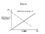
本実施形態では、前記図1の触媒装置3の下流側に配置する排ガスセンサ5として、触媒装置3が浄化するガス成分のうちのHCの濃度を検出するHCセンサを用いている。この場合、排ガスセンサ5の出力VSのHC濃度に対する特性は、図14に実線で示すように、HC濃度の増加に伴い、ほぼリニアに出力VSのレベルが大きくなるポジティブ特性のものである。
【0223】
ここで、触媒装置3によるHCの浄化特性を説明しておく。
【0224】
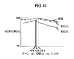
触媒装置3は、エンジン1の空燃比の変化に対して基本的には図15に示すようなHCの浄化特性(HCの浄化率の特性)を有する。この場合、図15の実線、破線、及び一点鎖線のグラフは、それぞれ、前記図2の実線、破線、及び一点鎖線のグラフに対応する劣化状態の触媒装置3に関するものである。
【0225】
図15に実線のグラフで示すように、新品の触媒装置3によるHCの浄化率は、エンジン1の空燃比がある値AF4(この値は、図2に示した空燃比の値AF1とほぼ一致する)よりもリーン側の空燃比域にあるときには、ほぼ一定(略100%)の最大の浄化率となる。そして、エンジン1の空燃比が上記の値AF4よりもリッチ側の空燃比域になると、HCの浄化率が低下する。
【0226】
また、触媒装置3の劣化がある程度進行すると、図15の破線や一点鎖線のグラフで示すように、HCの浄化率は、ある値AF5(:破線),AF6(:一点鎖線)の空燃比において極大値を採る(ピークを持つ)。そして、エンジン1の空燃比がHCの浄化率の極大値に対応する値AF5,AF6から、リッチ側及びリーン側のいずれに変化しても、HCの浄化率が減少していく。尚、空燃比の上記値AF5,AF6は、それぞれ、図2に示した空燃比の値AF2,AF3と概ね一致する。
【0227】
この場合、HCの浄化率の極大値からの減少は、リッチ側よりもリーン側の方うが若干、緩やかに生じる(グラフの傾きがリッチ側よりもリーン側の方が若干小さい)。尚、触媒装置3が劣化した状態におけるHCの浄化率の極大値は、触媒装置3の新品状態における浄化率の最大値よりも小さい。また、該極大値は、触媒装置3の劣化の進行に伴い小さくなる。
【0228】
このように触媒装置3によるHCの浄化率は、NOxの浄化率と同様、触媒装置3の新品状態を除いて、エンジン1の空燃比の変化に対して基本的には極大値を持つような特性を呈する。
【0229】
尚、触媒装置3の新品状態を含めた該触媒装置3の各劣化状態において、HCの浄化率が最大(極大)となるような空燃比の値(前記AF4,AF5,AF6等)は、基本的には触媒装置3の劣化が進行するに伴い、リーン側にシフトする。さらにそのような空燃比の値(AF4,AF5,AF6等)の付近におけるHCの浄化率の変化は、基本的には、触媒装置3の劣化が進行するに伴い、急峻になる(浄化率のグラフの凸形状がより先鋭になる)。
【0230】
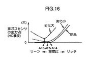
また、触媒装置3が上述のようなHCの浄化特性を有するため、該触媒装置3の下流側の排ガスセンサ5(HCセンサ)が検出するHC濃度、すなわち、触媒装置3による浄化後の排ガス中のHC濃度は、図16に示す如く、エンジン1の空燃比の変化に対して、基本的には、前記図15のグラフの上下を反転させたような形態の特性を呈することとなる。つまり、該HC濃度は、触媒装置3による浄化後のNOxと同様、触媒装置3の新品状態(図16の実線のグラフ)を除いて、基本的には、エンジン1の空燃比の変化に対して極小値を持つ特性(図16の破線又は一点鎖線のグラフ)となる。
【0231】
そして、本実施形態では、HC濃度に対する前記排ガスセンサ5の出力特性はポジティブ特性であるため、エンジン1の空燃比の変化に対する排ガスセンサ5の出力VSの特性も、図16に示したNOx濃度そのものの特性と同じになる。すなわち、その特性を改めて説明すれば、エンジン1の空燃比の変化に対する排ガスセンサ5(HCセンサ)の出力VSの特性は、触媒装置3の新品状態を除いて(ある程度劣化した状態では)、図16の破線あるいは一点鎖線のグラフで示す如く、触媒装置3によるHCの浄化率が極大となるようなエンジン1の空燃比(AF5,AF6等)において排ガスセンサ5の出力VSが極小値を採る特性(凹形状のグラフ特性)となる。また、触媒装置3の新品状態では、図16の実線のグラフで示す如く、ある値AF4の空燃比よりもリーン側の空燃比域、すなわち、HCの浄化率がほぼ一定の最大値(略100%)に維持されるような空燃比域において、排ガスセンサ5の出力VSはほぼ一定の最小レベル(略0V)に維持される。そして、エンジン1の空燃比が上記値AF4よりもリッチ側の空燃比になると、排ガスセンサ5の出力VSが増加していく。
【0232】
このような触媒装置3の浄化特性を考慮しつつ、本実施形態における目標空燃比算出制御器6の処理についてさらに説明する。
【0233】
上述のように、排ガスセンサ5としてのHCセンサの出力VSの、エンジン1の空燃比に対する特性(対空燃比特性)は、基本的には、前記第1の実施形態で説明したNOxセンサの出力の対空燃比特性と同様に、極小値をもつ(グラフ形状が凹形状となる)。
【0234】
従って、本実施形態における排ガスセンサ5(HCセンサ)の出力VSの対空燃比特性(これは排ガスセンサ5の出力VSから把握されるHC濃度の対空燃比特性でもある)は、前記第1の実施形態と同様に前記式(1)の形の二次関数のパラメータa1,b1,c1の値を同定することで、該二次関数により近似的に表現することができる。そして、触媒装置3によるHCの浄化率を最大(極大)とするようなエンジン1の目標空燃比KCMDは、基本的には、上記二次関数の関数値(排ガスセンサ5の関数出力VSH1)が極小値となるような空燃比の値として与えられる。
【0235】
そこで、本実施形態では、エンジン1の目標空燃比KCMDを求める目標空燃比算出制御器6は、排ガスセンサ5(HCセンサ)の出力VSの対空燃比特性を表現する非線形関数として、前記第1の実施形態と同様に、前記式(1)の形の二次関数を用いる。そして、その二次関数のパラメータa1,b1,c1の値を第1の実施形態で説明した通りのアルゴリズム(逐次型同定アルゴリズム)によって、同定する(前記式(2)〜式(6)、並びに図13を参照)。
【0236】
そして、本実施形態においても、目標空燃比算出制御器6は、基本的には、パラメータa1,b1,c1の値を同定した二次関数の関数値が極小値となるような空燃比の値を目標空燃比KCMDとして求める。この場合、この目標空燃比KCMDを規定する目標偏差空燃比kcmd(=KCMD−FLAF/BA SE)を、パラメータa1,b1の同定値を用いて前記式(7)により求めることができ、この目標偏差空燃比kcmdに空燃比基準値FLAF/BASEを加算すれば、目標空燃比KCMDが得られる。
【0237】
但し、本実施形態では、触媒装置3の新品状態では、前記第1の実施形態と異なる演算によって、目標空燃比KCMDを求めることとする。
【0238】
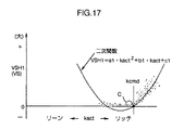
すなわち、触媒装置3の新品状態では、排ガスセンサ5(HCセンサ)の対空燃比特性は、図16に実線のグラフで示したようなものとなり、極小値をもたないと共に、リーン寄りの空燃比において出力VSがほぼ一定(略「0」)となる。そして、このような場合、例えば、図17に点描部分で示すような傾向で、排ガスセンサ5の出力VSと、LAFセンサ4による偏差空燃比kact(=KACT−FLAF/BASE)とのサンンプリングデータが得られ、このとき、パラメータa1,b1,c1の同定値により定まる二次関数のグラフは、同図17に実線で示すようなものとなる。このとき、該二次関数の関数値(関数出力VSH1)の極小値は、図17に示した如く、排ガスセンサ5の実際の出力VSが採り得ない負の値(HC濃度が略「0」のときの排ガスセンサ5の出力VSよりも小さい値)となる。
【0239】
また、触媒装置3の新品状態で、HCを含めて種々のガス成分(NOx等)の浄化率が高いものとなる空燃比は、二次関数の関数値が極小値となるような空燃比の値ではなく、概ね図17の点Cにおける空燃比の値の近傍の空燃比である。
【0240】
このため、本実施形態では、目標空燃比算出制御器6は、パラメータa1,b1,c1の同定値(最新の同定値)により定まる二次関数の極小値が負の値となるような場合、すなわち、パラメータa1,b1,c1の同定値が、b12−4・a1・c1>0という不等式を満たす場合には、該二次関数の関数値(排ガスセンサ5の関数出力VSH1)が「0」となるような偏差空燃比kactの値(この値は二つある)のうち、リッチ側の値(図17の点Cにおける偏差空燃比kactの値)を、目標偏差空燃比kcmdとして求める。そして、その目標偏差空燃比kcmdに空燃比基準値FLAF/BASEを加算することで、目標空燃比KCMDを求める。
【0241】
つまり、本実施形態では、目標空燃比算出制御器6は、二次関数のパラメータa1,b1,c1の同定値(詳しくは最新の同定値a1(k+1),b1(k+1),c1(k+1))により定まる判別式(b12−4・a1・c1)の値に応じて、次式(22)により、目標偏差空燃比kcmd(k)を求める。
【0242】
【数22】
そして、この式(22)に従って求めた目標偏差空燃比kcmd(k)に、前記式(10)のように空燃比基準値FLAF/BASEを加算することで、制御サイクル毎の目標空燃比KCDM(k)を決定する。
【0244】
この場合、前記式(22)では、b12−4・a1・c1≦0である場合は、前記第1の実施形態に関する式(9)と同じであるが、b12−4・a1・c1>0である場合(触媒装置3が新品状態である場合)は、式(9)と異なるものとなる。
【0245】
本実施形態における目標空燃比算出制御器6の処理は、この目標偏差空燃比kcmdの算出の演算処理、すなわち、前記図11のSTEP6における演算処理のみが第1の実施形態の実施形態と相違するものであり、その他の処理は、第1の実施形態と全く同一である。
【0246】
また、上述した以外の構成及び作動、例えば燃料供給制御器7の構成及び作動も第1の実施形態と全く同一である。
【0247】
かかる本実施形態の装置によれば、前記第1の実施形態で説明したものと同様の効果を奏することができる。すなわち、それを要約すれば、前記パラメータa1,b1,c1の同定によって、排ガスセンサ5(HCセンサ)の出力VSの対空燃比特性を良好に近似する二次関数を得ることができる。そして、この二次関数を用いることで、排ガスセンサ5(HCセンサ)が検出するHC濃度、すなわち、触媒装置3による浄化後のHC濃度が極小となるようなエンジン1の目標空燃比KCMDを求めることができる。そして、この目標空燃比KCMDにエンジン1の空燃比を適応制御器17を用いたフィードバック制御によって、操作することで、触媒装置3によるHCの良好な浄化、すなわち、HCの浄化率が極大となるような浄化を行なうことができる。
【0248】
さらに、パラメータa1,b1,c1の同定値により規定される二次関数の関数値である排ガスセンサ5の関数出力VSH1が負の値になるような触媒装置3の新品状態では、二次関数の関数値(関数出力VSH1)が「0」となるような空燃比の値のうちのリーン側の値が目標空燃比KCMDとして設定されるので、触媒装置3の劣化状態によらずに、HCを含めた種々のガス成分の触媒装置3による浄化を良好に行なうことができる。
【0249】
尚、本実施形態にあっても、前記第1の実施形態に関連して説明した変形態様が可能である。すなわち、排ガスセンサ5は、図14に仮想線で示すように、HC濃度の増加に伴い出力VSが小さくなるようなネガティブ特性のものを用いることも可能である。さらに、二次関数の独立変数は、排ガスセンサ5の出力VSに代えて、該出力VSから図14の特性に従って把握されるHC濃度を用いてもよい。
【0250】
次に、本発明の第3の実施形態を図18〜図20等を参照して説明する。尚、本実施形態のシステムは、前述の第1の実施形態のものと、システム構成は同一で、目標空燃比算出制御器の処理の一部(詳しくは図11のSTEP5,6の処理)のみが第1の実施形態と相違するものである。従って、本実施形態の説明では、第1の実施形態と同一部分については、第1の実施形態と同一の参照符号を使用し、説明を省略する。
【0251】
前記第1の実施形態で説明した前記図4に示した如く、排ガスセンサ5(ポジティブ特性のNOxセンサ)の実際の出力VSの対空燃比特性では、基本的には該出力VSが極小値となる空燃比の値(図4のAF2やAF3)の前後の空燃比域(当該空燃比の値よりもリーン側の空燃比域とリッチ側の空燃比域)でグラフの傾きが相違する。つまり、排ガスセンサ5の実際の出力VSが極小値となるような空燃比の値よりもリッチ側の空燃比域では、リーン側の空燃比域よりも上記対空燃比特性のグラフの傾きが基本的には小さい。
【0252】
従って、排ガスセンサ5の実際の出力VSの対空燃比特性(より詳しくは、出力VSが極小値となるような空燃比の値の近辺の空燃比域における特性)を、より実際の特性に整合させて表現する上では、それを表現するための非線形関数として、例えば三次関数を用いることが好ましいと考えられる。
【0253】
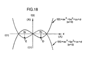
すなわち、三次関数を一般的にf(X)=aX3+bX2+cX+d(X:独立変数)という式により表したとき、そのグラフは、三次の項の係数aの値が正であるか負であるかによって、基本的には、図18に実線(a>0)あるいは破線(a<0)で示すような形状(極大値と極小値とを有する形状)となる。そして、これらのグラフにおいて、三次関数f(X)のグラフの極小点D,Eの近傍部分に着目すると、a>0である場合には、極小点DにおけるXの値XDよりも大きなXの値側でのグラフの傾きは、XDよりも小さなXの値側でのグラフの傾きよりも大きくなる。逆に、a<0である場合には、極小点EにおけるXの値XEよりも大きなXの値側でのグラフの傾きは、XEよりも小さなXの値側でのグラフの傾きよりも小さくなる。
【0254】
このような三次関数の特徴を考慮すると、排ガスセンサ5としてのNOxセンサの実際の出力VSの対空燃比特性の極小値の付近における前述のようなグラフの傾き形態を表現する上では、三次の項の係数(パラメータ)の値が負の値となるような三次関数により表現することが好ましいと考えられる。
【0255】
このようなことから、本実施形態では、排ガスセンサ5の出力VSの対空燃比特性を近似的に表現する非線形関数として三次関数を用いることとする。そして、該三次関数は、前記第1の実施形態の場合と同様に前記LAFセンサ4の偏差出力kactを独立変数、排ガスセンサ5の出力を従属変数として、次式(23)により定義する。
【0256】
【数23】
ここで、式(23)においては、この三次関数の関数値(従属変数の値)である排ガスセンサ5の出力(以下、関数出力という)の参照符号(変数記号)として「VSH2」を用いている。
【0258】
本実施形態では、この三次関数の式(23)の三次の項「kact3」に係る係数a2と、二次の項「kact2」に係る係数b2と、一次の項「kact」に係る係数c2と、定数項d2とが、目標空燃比算出制御器6の同定手段8としての機能によってその値を同定するパラメータである。そして、目標空燃比算出制御器6の同定手段8が、上記パラメータa2,b2,c2,d2の値を同定するアルゴリズムは、次のように構築された逐次型同定アルゴリズムである。
【0259】
尚、この同定アルゴリズムの基本的手法は、第1の実施形態と同様であるので、ここでは、簡略的に説明する。
【0260】
すなわち、この逐次型同定アルゴリズムでは、目標空燃比算出制御器6の制御サイクル毎に、LAFセンサ4の偏差出力の現在値kact(k)と、前記パラメータa2,b2, c2,d2の同定値の現在値a2(k),b2(k),c2(k),d2(k)(これは基本的には前回の制御サイクルで求められた同定値である)とを用いて次式(24)の演算を行うことで、各制御サイクルにおける排ガスセンサ5の関数出力VSH2(k)(三次関数の関数値)が求められる。
【0261】
【数24】
さらに、次式(25)のように、上記関数出力VSH2(k)と、現在の制御サイクルにおける排ガスセンサ5の実際の出力VS(k)との間の偏差としての同定誤差ID/E2(k)が求められる。
【0263】
【数25】
そして、この同定誤差ID/E2 (k)を用いて、前記式(24)の但し書きで定義した同定パラメータベクトルΘ2を次式(26)により更新することで、新たな同定パラメータベクトルΘ2(k+1)、すなわち、該同定パラメータベクトルΘ2の成分であるパラメータa2,b2,c2,d2の新たな同定値a2(k+1),b2(k+1),c2(k+1),d2(k+1)が求められる。
【0265】
【数26】
ここで、式(26)中の「Kp2(k)」は、制御サイクル毎に次式(27)により決定される四次のベクトルである。
【0267】
【数27】
また、この式(27)中の「ξ2(k)」は前記式(24)の但し書きで定義したベクトル、「P2(k)」は、制御サイクル毎に次式(28)の漸化式により更新される四次の正方行列である。
【0269】
【数28】
この場合、前記第1の実施形態の場合と同様に、式(28)のλ3,λ4の設定の仕方によって、各種の具体的な同定アルゴリズムが定まる(但し、0<λ3≦1及び0≦λ4<2)。本実施形態では、例えば逐次型最小二乗法(この場合、λ3=λ4=1)の同定アルゴリズムを採用している。
【0271】
以上説明したアルゴリズムが、本実施形態で三次関数のパラメータa2,b2,c2,d2の値を同定するための逐次型同定アルゴリズムの内容である。
【0272】
尚、本実施形態では、NOxセンサである排ガスセンサ5の出力VSの対空燃比特性(特に出力VSの極小値の付近におけるグラフの傾き形態)を三次関数により良好に近似する上では、前述したように該三次関数の三次の項の係数であるパラメータa2の値は負の値であることが好ましい。このため、本実施形態では、パタメータa2の同定値a2(k+1)が外乱等の影響で、a2(k+1)≧0となった場合には、その同定値a2(k+1)を後述するように強制的に負の値に制限するようにしている。
【0273】
また、本実施形態における目標空燃比算出制御器6は、上述のようにしてパラメータa2,b2,c2,d2の値を同定した三次関数を用いて、次のように、エンジン1の目標空燃比KCMD(LAFセンサ4が検出する空燃比の目標値)を制御サイクル毎に求める。
【0274】
すなわち、上述のようにパラメータa2,b2,c2,d2の値を同定した三次関数は、排ガスセンサ5(NOxセンサ)の出力VSの対空燃比特性、特に、該出力VSが極小値となるような空燃比の近傍の空燃比域における対空燃比特性を良好に近似し得るものとなる。
【0275】
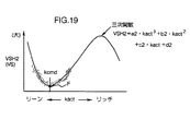
例えば、触媒装置3のある劣化状態において、排ガスセンサ5(NOxセンサ)の出力VSと、LAFセンサ4による偏差空燃比kact(=KACT−FLAF/BASE)とのサンプリングデータは、図19に点描部分で示すような傾向で得られ、このとき、パラメータa2,b2,c2,d2の同定値により定まる三次関数のグラフは、同図19に実線で示すような形状のものとなる。
【0276】
そして、本実施形態では、前記第1の実施形態と同様に、排ガスセンサ5の出力VSが極小となるようなエンジン1の空燃比、すなわち、触媒装置3によるNOxの浄化率が極大となるような空燃比を目標空燃比KCMDとして求める。
【0277】
そこで、本実施形態では、目標空燃比算出制御器6は、制御サイクル毎に、前記三次関数の関数値(前記関数出力VSH2)が極小値となるような偏差空燃比kactの値(図19の点Fにおける偏差空燃比kactの値)を目標偏差空燃比kcmd(=KCMD−FLAF/BASE)として求める。そして、この目標偏差空燃比kcmdに前記空燃比基準値FLAF/BASEを加算することで、目標空燃比KCMDを求める。
【0278】
この場合、前記目標偏差空燃比kcmd、すなわち、三次関数の関数値(関数出力VSH2)が極小値となる偏差空燃比kactの値は、パラメータa1の同定値が負の値となることを考慮すると、該三次関数の一次導関数の値が「0」となるような偏差空燃比kactの値(これは基本的には三次関数が極小値及び極大値をもつことに対応して二つある)のうち、リーン側の値である。従って、前記目標偏差空燃比kcmdは、パラメータa2,b2,c2,d2のうちのパラメータa2,b2,c2の同定値(詳しくは最新の同定値a2(k+1),b2(k+1),c2(k+1))を用いて次式(29)により求めることができる。
【0279】
【数29】
以上説明したことを基礎として、本実施形態の装置の作動をさらに説明すると、その作動は、前述した第1の実施形態のものと、目標空燃比算出制御器6による前記図11のSTEP5,6の処理(同定演算の処理及び目標偏差空燃比kcmdの算出処理)のみが相違し、その他の目標空燃比算出制御器6の処理や、燃料供給制御器7の処理は第1の実施形態のものと同一である。
【0281】
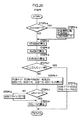
この場合、図11のSTEP5の同定演算の処理は、本実施形態では図20のフローチャートに示すように行なわれる。尚、この処理の基本的手順は、第1の実施形態のものと同様であるので、ここでは簡略的に説明する。
【0282】
すなわち、目標空燃比算出制御器6は、まず、STEP5−a,5−bにおいて、前記第1の実施形態と同様に、前記図11のSTEP1でフラグf/id/resetの値が「1」に設定された場合に、同定演算に関する初期化を行なう。この初期化では、三次関数のパラメータa1,b1,c1,d1の各同定値があらかじめ定めた初期値に設定され、また、前記式(28)の行列P2(対角行列)の各成分があらかじめ定めた初期値に設定される。
【0283】
次いで、目標空燃比算出制御器6は、STEP5−c,5−d,5−eにおいて、LAFセンサ4の現在の偏差出力kact(k)に対応する排ガスセンサ5の関数出力VSH2(k)(三次関数の関数値)と、前記式(26)の演算に必要な同定誤差ID/E2(k)及びベクトルKp2(k)とを、それぞれ、前記式(24)、(27)、(25)に従って順次算出する。
【0284】
次いで、目標空燃比算出制御器6は、前記第1の実施形態と同様に、エンジン1のフュエルカット中であるか否かを判断する(STEP5−f)。そして、フュエルカット中である場合には、STEP5−gにおいて、三次関数のパラメータa2,b2,c2, d2の同定値を更新することなく、それらの同定値を成分とする前記同定パラメータベクトルΘ2(式(24)の但し書きを参照)を現在値に保持する。また、前記行列P2を現在値に保持する。
【0285】
一方、STEP5−fでフュエルカット中でない場合には、前記STEP5−d,5−eで求めたベクトルKp2(k)及び同定誤差ID/E2(k)を用いて、前記式(26)に従って同定パラメータベクトルΘ2を更新することで、パラメータa2,b2,c2,d2の新たな同定値a2(k+1),b2(k+1),c2(k+1),d2(k+1)を求める(STEP5−h)。
【0286】
次いで、目標空燃比算出制御器6は、パラメータa2の新たな同定値a2(k+1)の値が負の値であるか否かを判断する(STEP5−i)。
【0287】
このとき、前述のように、排ガスセンサ5(NOxセンサ)の出力VSの対空燃比特性、特に、該出力VSの極小値付近における当該対空燃比特性のグラフの傾き形態(出力VSの極小値に対応する空燃比よりもリーン側では、リッチ側よいりもグラフの傾きが大きくなる形態)を、三次関数により適正に近似する上では、三次関数の三次の項の係数であるパラメータa2の同定値は負の値であることが望ましい。
【0288】
このため、本実施形態では、STEP5−iの判断で、a2(k+1)≧0となっていた場合には、パラメータa2の最新の同定値a2(k+1)の値を、あらかじめ負の値(例えば0.01)に定めた所定値ε2に強制的に設定しなおす(STEP5−j)。これにより、パラメータa1の同定値は、排ガスセンサ5の出力VSの対空燃比特性のグラフの極小値付近の傾き形態と、三次関数のグラフの極小値付近の傾き形態とが整合するような、負の値に制限される。
【0289】
このようなパラメータa2の同定値a2(k+1)の制限処理を行なった後、目標空燃比算出制御器6は、次回の制御サイクルにおける演算処理のために、前記行列P2を前記式(28)に従って更新する(STEP5−k)。
【0290】
以上説明した図20の処理が、本実施形態において、目標空燃比算出制御器6が図11のSTEP5で実行する処理である。
【0291】
そして、本実施形態では、目標空燃比算出制御器6は、図11のSTEP6においては、前述の如く得られるパラメータa2,b2,c2の最新の同定値a2(k+1),b2(k+1),c2(k+1)を用いて、前記式(29)の演算を行うことで、現在の制御サイクルにおける目標偏差空燃比kcmd(k)を求める。
【0292】
以上説明した以外の目標空燃比算出制御器6の処理(図11のSTEP5,6以外の処理)は、前述の第1の実施形態と全く同一である。
【0293】
かかる本実施形態の装置によれば、排ガスセンサ5(NOxセンサ)の出力VSの対空燃比特性を表現する非線形関数として三次関数を用い、この三次関数のパラメータa2,b2,c2,d2を逐次同定する。このため、排ガスセンサ5(NOxセンサ)の出力VSの対空燃比特性を、その特性のグラフの傾き形態を含めてより良好に近似する三次関数を得ることができる。そして、この三次関数を用いることで、排ガスセンサ5(NOxセンサ)が検出するNOx濃度、すなわち、触媒装置3による浄化後のNOx濃度が極小となるようなエンジン1の目標空燃比KCMDをより精度よく求めることができる。そして、この目標空燃比KCMDにエンジン1の空燃比をフィードバック制御することで、触媒装置3によるNOxの良好な浄化、すなわち、NOxの浄化率が極大となるような浄化を行なうことができる。ひいては、NOxを含めた種々のガス成分の浄化を良好に行なうことができる。
【0294】
尚、本実施形態にあっても、前記第1の実施形態に関連して説明した変形態様が可能である。
【0295】
すなわち、三次関数の独立変数は、排ガスセンサ5(NOxセンサ)の出力VSに代えて、該出力VSから図2の特性に従って把握されるNOx濃度を用いてもよい。
【0296】
また、排ガスセンサ5(NOxセンサ)は、図2に仮想線で示したネガティブ特性のNOxセンサを用いることも可能である。この場合、排ガスセンサ5が検出するNOx濃度が極小値となるようなエンジン1の空燃比では、排ガスセンサ5の出力は極大値となる。従って、例えば、この場合の三次関数を、排ガスセンサ5の出力を従属変数として、前記式(23)の形式で表したとき、その三次関数の関数値が極大値となるような偏差空燃比kactの値を求めれば、排ガスセンサ5が検出するNOx濃度が極小値となるようなエンジン1の目標空燃比を求めることができる。すなわち、触媒装置3によるNOxの浄化率が極大となるようなエンジン1の目標空燃比を求めることができる。但し、この場合、ネガティブ特性の排ガスセンサ(NOxセンサ)では、その出力の対空燃比特性のグラフの極大値付近におけるグラフの傾きは、該極大値に対応する空燃比の値よりもリーン側の方がリッチ側よりも大きくなるので、上記三次関数の三次の項の係数であるパラメータの値は、前記第3の実施形態の場合と逆に正の値に制限することが好ましい。
【0297】
次に本発明の第4の実施形態を図21等を参照して説明する。尚、本実施形態のシステムは、前述の第3の実施形態のもの(三次関数を用いるもの)と、排ガスセンサの種類(検出するガス成分の種類)と、目標空燃比算出制御器の処理の一部(詳しくは図11のSTEP5の処理の一部とSTEP6の処理)とが相違し、他のシステム構成及び作動は、第3の実施形態と同一である。従って、本実施形態の説明では、第3の実施形態と同一部分については、第1の実施形態と同一の参照符号を使用し、説明を省略する。
【0298】
本実施形態は、排ガスセンサ5として、前記第2の実施形態で説明したHCセンサ(詳しくはポジティブ特性のHCセンサ)を使用するものである。また、この排ガスセンサ5の出力VSの対空燃比特性を表現するための非線形関数として、前記第3の実施形態と同様に前記式(23)の形式の三次関数を用いるものである。
【0299】
この場合、HCセンサである排ガスセンサ5の出力VSの対空燃比特性では、前記図16に示した如く、基本的には該出力VSが極小値となる空燃比の値(図16のAF5やAF6)の前後の空燃比域(当該空燃比の値よりもリーン側の空燃比域とリッチ側の空燃比域)でグラフの傾きが相違する。つまり、排ガスセンサ5(HCセンサ)の実際の出力VSが極小値となるような空燃比の値よりもリーン側の空燃比域では、NOxセンサの場合と逆に、リッチ側の空燃比域よりも上記対空燃比特性のグラフの傾きが基本的には小さい。
【0300】
従って、排ガスセンサ5(HCセンサ)の実際の出力VSの極小値付近における対空燃比特性を、式(23)の形式の三次関数により実際の特性に整合させて表現する上では、該三次関数の三次の項の係数であるパラメータa2の同定値を前記第3の実施形態の場合と逆に、正の値に制限する(三次関数のグラフ形状を図18の実線のようなグラフ形状とする)ことが望ましい。
【0301】
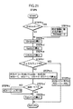
このようなことから、本実施形態における目標空燃比算出制御器6は、図11のSTEP5において、図21のフローチャートに示す同定演算の処理を実行することで、前記式(23)の三次関数のパラメータa2,b2,c2,d2の同定値a2(k+1),b2(k+1),c2(k+1),d2(k+1)を求める。
【0302】
尚、この図21のフローチャートの処理は、前記第3の実施形態における図20のフローチャートの処理と一部のみが相違するだけなので、第3の実施形態と同一の処理部分については、図20と同一のSTEP番号を付して、説明を省略する。
【0303】
すなわち、本実施形態では、STEP5−hにおいて前記第3の実施形態で説明した通りに三次関数のパラメータa2,b2,c2,d2の同定値a2(k+1),b2(k+1),c2(k+1),d2(k+1)を求めた後、パラメータa2の同定値a2(k+1)が正の値であるか否かを判断する(STEP5−i’)。そして、a2(k+1)>0である場合には、前記STEP5−kの処理を行なうが、a2(k+1)≦0である場合には、同定値a2(k+1)の値を、あらかじめ正の値(例えば0.01)に定めた所定値ε3に設定しなおした後(STEP5−j’)に、STEP5−kの処理を行なう。これ以外の処理は、図20の処理と全く同一である。
【0304】
上記のような処理によって、三次関数のパラメータa1の同定値は、HCセンサである排ガスセンサ5の出力VSの対空燃比特性のグラフの極小値付近の傾き形態と、三次関数のグラフの極小値付近の傾き形態とが整合するような、正の値に制限される。
【0305】
また、上記のようにして図11のSTEP5の処理を行なう本実施形態では、図11のSTEP6において、次のようにして、排ガスセンサ5(HCセンサ)の出力VSが極小となるようなエンジン1の目標偏差空燃比kcmd、すなわち、触媒装置3によるHCの浄化率が極大となるような目標偏差空燃比kcmdを求める。
【0306】
すなわち、前記目標偏差空燃比kcmdは、三次関数の関数値(関数出力VSH2)が極小値となる偏差空燃比kactの値である。そして、このような偏差空燃比kactの値は、パラメータa1の同定値が正の値となることを考慮すると、該三次関数の一次導関数の値が「0」となるような偏差空燃比kactの値(これは基本的には三次関数が極小値及び極大値をもつことに対応して二つある)のうち、リッチ側の値である。
【0307】
そこで、本実施形態では、前記目標偏差空燃比kcmdは、パラメータa2,b2,c2,d2のうちのパラメータa2,b2,c2の同定値(詳しくは最新の同定値a2(k+1),b2(k+1),c2(k+1))を用いて次式(30)により求める。
【0308】
【数30】
以上説明した以外の目標空燃比算出制御器6の処理は前記第3の実施形態と同一である。また、燃料供給制御器7の処理は前述の第1〜第3の各実施形態と同一である。
【0310】
かかる本実施形態の装置によれば、第3の実施形態と同様に、排ガスセンサ5(HCセンサ)の出力VSの対空燃比特性を表現する非線形関数として三次関数を用い、この三次関数のパラメータa2,b2,c2,d2を逐次同定する。このため、排ガスセンサ5(HCセンサ)の出力VSの対空燃比特性を、その特性のグラフの傾き形態を含めてより良好に近似する三次関数を得ることができる。そして、この三次関数を用いることで、排ガスセンサ5(HCセンサ)が検出するHC濃度、すなわち、触媒装置3による浄化後のHC濃度が極小となるようなエンジン1の目標空燃比KCMDをより精度よく求めることができる。そして、この目標空燃比KCMDにエンジン1の空燃比をフィードバック制御することで、HCの浄化率が極大となるような浄化を行なうことができる。
【0311】
尚、本実施形態にあっても、前記第3の実施形態と同様の変形態様が可能である。すなわち、三次関数の独立変数は、排ガスセンサ5(HCセンサ)の出力VSに代えて、該出力VSから図14の特性に従って把握されるHC濃度を用いてもよい。
【0312】
また、排ガスセンサ5(HCセンサ)は、図14に仮想線で示したネガティブ特性のHCセンサを用いることも可能である。この場合、例えば、排ガスセンサ5の出力を従属変数として、前記式(23)の形式で三次関数を表したとき、その三次関数の関数値が極大値となるような偏差空燃比kactの値を求めれば、排ガスセンサ5が検出するHC濃度が極小値となるようなエンジン1の目標空燃比を求めることができる。但し、この場合、排ガスセンサ(HCセンサ)の出力の対空燃比特性のグラフの傾き形態を考慮すると、三次関数の三次の項の係数の同定値は、第4の実施形態と逆に、負の値に制限することが好ましい。
【0313】
また、三次関数を用いる前記第3及び第4の実施形態では採用していないが、前記式(29)あるいは式(30)の平方根内の値(b22−3・a2・c2)が負の値もしくは「0」とならないように、パラメータa2,b2,c2,d2の同定値を制限しながら、該パラメータa2,b2,c2,d2の値を同定するようにしてもよい。あるいは、パラメータa2,b2,c2,d2の同定値によって求められる式(29)あるいは式(30)の平方根内の値(b22−3・a2・c2)が負の値もしくは「0」となるような場合には、例えば三次関数の関数値(関数出力VSH2)が「0」となるよう偏差空燃比kactの値を目標偏差空燃比kcmdとして得るようにしてもよい。
【0314】
また、以上説明した第1〜第4の実施形態では、排ガスセンサ5としてNOxセンサあるいはHCセンサを用いたが、触媒装置3により浄化する他のガス成分、例えば、CO(一酸化炭素)の濃度を検出するCOセンサ等を用いてそのCO濃度が極小となるようにエンジン1の空燃比を制御するようにすることも可能である。
【0315】
また、前述の第1〜第4の実施形態では、排ガスセンサの出力あるいはその出力から把握されるガス成分の濃度の対空燃比特性を表現する非線形関数として、二次関数あるいは三次関数を用いたが、例えば双極線関数等の他の形式の非線形関数を用いることも可能である。
【図面の簡単な説明】
【図1】本発明の第1の実施形態の装置の全体的システム構成を示すブロック図。
【図2】図1の装置で使用する排ガスセンサ(NOxセンサ)のNOx濃度に対する出力特性を示す線図。
【図3】図1の装置の触媒装置によるNOxの浄化特性を示す線図。
【図4】図1の装置で使用する排ガスセンサ(NOxセンサ)の出力あるいはその排ガスセンサが検出するNOx濃度の空燃比に対する特性を示す線図。
【図5】図1の装置の目標空燃比算出制御器の要部の処理を説明するための線図。
【図6】図1の装置の目標空燃比算出制御器の要部の処理を説明するための線図。
【図7】図1の装置の燃料供給制御器の基本構成を示すブロック図。
【図8】図7の燃料供給制御器が備える適応制御器の基本構成を示すブロック図。
【図9】図1の装置の燃料供給制御器の処理を説明するためのフローチャート。
【図10】図9のフローチャートのサブルーチン処理を示すフローチャート。
【図11】図1の装置の目標空燃比算出制御器の処理を説明するためのフローチャート。
【図12】図11のフローチャートのサブルーチン処理を示すフローチャート。
【図13】図11のフローチャートのサブルーチン処理を示すフローチャート。
【図14】本発明の第2の実施形態で使用する排ガスセンサ(HCセンサ)のHC濃度に対する出力特性を示す線図。
【図15】第2の実施形態における触媒装置(図1の触媒装置)によるHCの浄化特性を示す線図。
【図16】第2の実施形態で使用する排ガスセンサ(HCセンサ)の出力あるいはその排ガスセンサが検出するHC濃度の空燃比に対する特性を示す線図。
【図17】第2の実施形態における目標空燃比の算出処理を説明するための線図。
【図18】本発明の第3の実施形態で用いる三次関数のグラフを示す線図。
【図19】第3の実施形態における目標空燃比の算出処理を説明するための線図。
【図20】第3の実施形態における要部の処理を説明するためのフローチャート。
【図21】第4の実施形態における要部の処理を説明するためのフローチャート。
【符号の説明】
1…エンジン、2…排気管(排気通路)、3…触媒装置、4…LAFセンサ(空燃比センサ)、5…排ガスセンサ、6…燃料供給制御器(空燃比操作手段)、7…目標空燃比算出制御器(目標空燃比算出手段)、8…同定手段。[0001]
BACKGROUND OF THE INVENTION
The present invention relates to an air-fuel ratio control apparatus for an internal combustion engine.
[0002]
[Prior art]
Generally, in an internal combustion engine, a catalyst device constituted by a three-way catalyst or the like is provided in an exhaust passage, and this catalyst device removes gas components such as HC (hydrocarbon) and NOx (nitrogen oxide) contained in exhaust gas. I try to purify it. In recent years, a technique for controlling the air-fuel ratio of the air-fuel mixture burned in the internal combustion engine has been proposed in order to increase the purification rate of HC, NOx and the like by the catalyst device as much as possible.
[0003]
For example, the applicant of the present application uses a feedback control process to catalyze the output (detected value of oxygen concentration) of an O2 sensor (oxygen concentration sensor) arranged downstream of the catalyst device to a predetermined target value (a constant value). The target value (target air-fuel ratio) of the exhaust gas upstream of the device is sequentially determined, and the air-fuel mixture burned in the internal combustion engine so that the target air-fuel ratio becomes the air-fuel ratio of the exhaust gas upstream of the catalyst device. A technique for ensuring the optimum purification performance of the catalyst device by manipulating the fuel ratio has been proposed (for example, Japanese Patent Laid-Open No. 9-324681). Here, the air-fuel ratio of the exhaust gas upstream of the catalyst device is more specifically the air-fuel ratio grasped from the oxygen concentration of the exhaust gas entering the catalyst device, and the air-fuel ratio combusted by the internal combustion engine to become exhaust gas. It represents the air-fuel ratio (hereinafter, this air-fuel ratio is simply referred to as the air-fuel ratio of the internal combustion engine).
[0004]
In this way, by controlling the air-fuel ratio of the internal combustion engine to an air-fuel ratio state in which the output of the O2 sensor downstream of the catalyst device converges (sets) to a predetermined target value, HC, NOx, etc. by the catalyst device It is possible to ensure optimum purification performance (purification performance that maximizes the purification rate of HC, NOx, etc.) regardless of the deterioration state of the catalyst device.
[0005]
On the other hand, in recent years, exhaust gas sensors (specifically, HC, NOx, etc.) that can detect the concentration of each type of gas component purified by a catalytic device (hereinafter referred to as a purification component) with relatively high accuracy (specifically, HC sensors and NOx sensors) have been developed. Note that this type of exhaust gas sensor is generally one in which the output level of the sensor increases almost linearly as the concentration of the purification component to be detected increases. Conversely, the concentration of the purification component increases. In some cases, the output level of the sensor becomes smaller. In the following description, the output characteristics of the former type exhaust gas sensor may be referred to as positive characteristics, and the output characteristics of the latter type exhaust gas sensor may be referred to as negative characteristics.
[0006]
By using such an exhaust gas sensor, it is considered possible to control the purification state of the purification component by the catalyst device to a desired state while directly observing the concentration of the purification component to be purified by the catalyst device. .
[0007]
For example, the exhaust gas sensor as described above is arranged on the downstream side of the catalyst device, and the internal combustion engine is configured so that the output of the exhaust gas sensor or the concentration of the purification component grasped from the output (detected value of the concentration) becomes a desired value. It is conceivable to determine the target air-fuel ratio of the engine and control the air-fuel ratio state of the air-fuel mixture burned in the internal combustion engine according to the target air-fuel ratio.
[0008]
However, according to the knowledge of the inventors of the present application, the purification rate of the purification components such as HC and NOx by the catalyst device is basically a certain value of the air-fuel ratio of the internal combustion engine (basically in the vicinity of the theoretical air-fuel ratio). Value), the maximum (maximum) value is obtained, and the purification rate of the purification component decreases even if the air-fuel ratio of the internal combustion engine deviates to either the lean side or the rich side with respect to the air-fuel ratio value. Therefore, the concentration of the purification component grasped from the output of the exhaust gas sensor arranged on the downstream side of the catalyst device has a minimum value with respect to the change in the air-fuel ratio of the internal combustion engine. Further, even in the output of the exhaust gas sensor itself, the positive characteristic has a minimum value with respect to the change in the air-fuel ratio of the internal combustion engine, and the negative characteristic has in response to the change in the air-fuel ratio of the internal combustion engine. Will have a maximum value.
[0009]
For this reason, when the exhaust gas sensor output or the concentration of the purification component grasped from the output has a deviation from the desired value, the air-fuel ratio of the internal combustion engine is set to the lean side and the rich side in order to eliminate the deviation. It is difficult to specify which side of the side should be changed. Therefore, it is difficult to determine the target air-fuel ratio for controlling the output of the exhaust gas sensor to a desired value by the feedback control method as in the prior art in which the O2 sensor is arranged on the downstream side of the catalyst device.
[0010]
For this reason, a novel technology that arranges an exhaust gas sensor for detecting the concentration of gas components to be purified by a catalytic device such as HC and NOx on the downstream side of the catalytic device and controls the output of the exhaust gas sensor to a desired value. Was desired.
[0011]
[Problems to be solved by the invention]
The present invention has been made in view of such a background, and is grasped from the output of an exhaust gas sensor arranged on the downstream side of the catalyst device to detect the concentration of gas components to be purified by the catalyst device, such as HC and NOx, and the output thereof. An object of the present invention is to provide an air-fuel ratio control apparatus for an internal combustion engine that can satisfactorily control the concentration of the gas component to a desired value.
[0012]
In particular, an object of the present invention is to provide an air-fuel ratio control device for an internal combustion engine that can satisfactorily purify a gas component detected by an exhaust gas sensor using a catalyst device.
[0013]
[Means for Solving the Problems]
In order to achieve this object, an air-fuel ratio control apparatus for an internal combustion engine according to the present invention is provided downstream of the catalyst apparatus to detect the concentration of a specific component in exhaust gas purified by a catalyst apparatus provided in an exhaust passage of the internal combustion engine. The exhaust gas sensor arranged on the side and the concentration of the specific component detected by the exhaust gas sensor are included in a nonlinear function of a predetermined format to express the correlation characteristic with respect to the air-fuel ratio of the exhaust gas upstream of the catalyst device. Identifying means for identifying the parameter value using data representing the air-fuel ratio of the exhaust gas upstream of the catalyst device and output data of the exhaust gas sensor; and the nonlinear means for identifying the parameter value by the identifying means An air-fuel ratio value at which the concentration of the specific component represented by the function value of the function becomes a value satisfying a predetermined condition is obtained using the identification value of the parameter of the nonlinear function, and the obtained value is obtained. Target air-fuel ratio calculating means for obtaining the target air-fuel ratio as a target air-fuel ratio upstream of the catalyst device, and an air-fuel mixture burned in the internal combustion engine in accordance with the target air-fuel ratio determined by the target air-fuel ratio calculating means And an air-fuel ratio operating means for operating the air-fuel ratio.
[0014]
More specifically, the nonlinear function expresses the air-fuel ratio of the exhaust gas upstream of the catalyst device (for example, the output of the sensor for detecting the air-fuel ratio, the air-fuel ratio grasped from the output, or the air-fuel ratio Target value) is an independent variable, and the output of the exhaust gas sensor and the concentration of the specific component grasped from the output are dependent variables. As a form of the nonlinear function suitable for the present invention, for example, a high-order function such as a quadratic function or a cubic function can be cited. More specifically, the parameter is a parameter that defines a graph shape of the nonlinear function. For example, when the form of the nonlinear function is a high-order function such as a quadratic function or a cubic function, a coefficient or a constant term related to each order term is the parameter.
[0015]
Further, the air-fuel ratio of the exhaust gas upstream of the catalyst device is specifically the air-fuel ratio grasped from the oxygen concentration of the exhaust gas as described above. In the following description of the present invention, this air-fuel ratio is sometimes simply referred to as the air-fuel ratio of the internal combustion engine.
[0016]
According to the present invention, the identification unit uses the data representing the air-fuel ratio of the internal combustion engine and the output data of the exhaust gas sensor (data of the detected value of the concentration of the specific component) to determine the parameter of the nonlinear function. By identifying the value, a nonlinear function that approximates the correlation characteristic of the concentration of the specific component detected by the exhaust gas sensor with the air-fuel ratio of the internal combustion engine is determined (the graph shape of the nonlinear function is determined). Will be).
[0017]
At this time, the concentration of the specific component detected by the exhaust gas sensor (the concentration of the specific component after purification by the catalytic device) generally has a minimum value with respect to the change in the air-fuel ratio of the internal combustion engine, as described above. Such correlation characteristics can be accurately expressed by an appropriate type of nonlinear function such as a quadratic function or a cubic function.
[0018]
When the non-linear function expressing the correlation characteristic is determined by identifying the parameter value as described above, the concentration of the specific component represented by the function value of the non-linear function (the value of the dependent variable) is a predetermined value. The value of the air-fuel ratio of the internal combustion engine (the value of the independent variable of the nonlinear function) that satisfies the condition (desired value) can be calculated using the identification value of the parameter of the nonlinear function. Since the nonlinear function approximates the correlation characteristic, the value of such an air-fuel ratio is an empty value that can make the actual concentration of the specific component detected by the exhaust gas sensor the above desired value. It becomes the value of the fuel ratio.
[0019]
Therefore, in the present invention, the target air-fuel ratio calculating means identifies the air-fuel ratio value at which the concentration of the specific component represented by the function value of the nonlinear function satisfies a predetermined condition as the parameter of the nonlinear function. The obtained air-fuel ratio value is obtained as the target air-fuel ratio of the internal combustion engine (the target value of the air-fuel ratio of the exhaust gas upstream of the catalyst device). Then, the air-fuel ratio operation means operates the air-fuel ratio of the air-fuel mixture burned in the internal combustion engine in accordance with the obtained target air-fuel ratio. Thereby, the concentration of the specific component detected by the exhaust gas sensor becomes a value that satisfies a predetermined condition, that is, the output of the exhaust gas sensor or the concentration of the specific component grasped from the output (the detected value of the concentration). The air-fuel ratio of the internal combustion engine is manipulated so that) becomes a desired value.
[0020]
Therefore, according to the present invention, the output of the exhaust gas sensor on the downstream side of the catalyst device and the concentration of the specific component grasped from the output can be favorably controlled to a desired value.
[0021]
The specific component whose concentration is detected by the exhaust gas sensor is specifically HC (hydrocarbon), NOx (nitrogen oxide), or the like.
[0022]
In the present invention, the data indicating the air-fuel ratio of the internal combustion engine (the air-fuel ratio of the exhaust gas upstream of the catalyst device) used by the identifying means for identifying the parameter value of the nonlinear function is, for example, the air-fuel ratio. Although it may be data representing the value itself, it is preferably data representing the deviation between the air-fuel ratio of the internal combustion engine and a predetermined reference value.
[0023]
Thus, by identifying the parameter value of the nonlinear function using the data representing the deviation between the air-fuel ratio of the internal combustion engine and the predetermined reference value, the accuracy of the identified value can be increased.
[0024]
In the present invention, it is also possible for the identification means to use, for example, a target air-fuel ratio determined by the target air-fuel ratio calculation means as the air-fuel ratio of the internal combustion engine in order to identify the parameter value of the nonlinear function. However, preferably, an air-fuel ratio sensor for detecting the air-fuel ratio of the internal combustion engine is provided upstream of the catalyst device. The identification means uses an air-fuel ratio detected by the air-fuel ratio sensor as an air-fuel ratio of the internal combustion engine for identifying the parameter value of the nonlinear function.
[0025]
The parameter value of the nonlinear function is identified by using the actual value of the air-fuel ratio detected by the air-fuel ratio sensor, that is, the air-fuel ratio of the internal combustion engine (the air-fuel ratio of the exhaust gas upstream of the catalyst device). Thus, the identification value can be obtained with high accuracy.
[0026]
In the present invention having the air-fuel ratio sensor as described above, the air-fuel ratio operation means feeds back so that the air-fuel ratio detected by the air-fuel ratio sensor converges to the target air-fuel ratio obtained by the target air-fuel ratio calculation means. The air-fuel ratio of the air-fuel mixture burned by the internal combustion engine is controlled by the control.
[0027]
As a result, the air-fuel ratio of the internal combustion engine can be appropriately controlled to the target air-fuel ratio, and consequently the output of the exhaust gas sensor can be accurately controlled to a desired value. As a result, it is possible to ensure the desired purification ability of the specific component by the catalyst device.
[0028]
The air-fuel ratio feedback control of the internal combustion engine is preferably performed by a recurrence type feedback control means such as an adaptive controller. Here, the recurrence formula type feedback control means provides a new feedback by a predetermined recurrence formula including a predetermined number of time-series data before the present of the feedback operation amount of the air-fuel ratio (for example, the correction amount of the fuel supply amount). The operation amount is obtained.
[0029]
In the present invention as described above, the target air-fuel ratio calculating means obtains, as the target air-fuel ratio, the value of the air-fuel ratio at which the concentration of the specific component represented by the function value of the nonlinear function becomes a minimum value. Is preferred.
[0030]
In this case, the target air-fuel ratio becomes a target air-fuel ratio such that the concentration of the specific component detected by the exhaust gas sensor, that is, the concentration of the specific component after purification by the catalyst device becomes a minimum value. Therefore, when the air-fuel ratio of the air-fuel mixture burned in the internal combustion engine is manipulated according to the target air-fuel ratio, the air-fuel ratio of the internal combustion engine becomes such that the purification rate of the specific component by the catalyst device becomes maximum. Will be controlled. Thereby, the optimal purification of the specific component by the catalyst device (purification that maximizes the purification rate of the specific component) can be performed. In other words, the purification capability of the specific component by the catalyst device can be maximized.
[0031]
Note that when the dependent variable of the nonlinear function is the concentration of a specific component grasped from the output of the exhaust gas sensor, the target air-fuel ratio is an air-fuel ratio value at which the function value of the nonlinear function itself is a minimum value. . In addition, when the dependent variable of the nonlinear function is the output of the exhaust gas sensor, the characteristic of the output of the exhaust gas sensor with respect to the concentration of the specific component is the positive characteristic (the characteristic that the output increases as the concentration increases). ), The target air-fuel ratio is the value of the air-fuel ratio at which the function value of the nonlinear function itself is a minimum value, as described above. On the other hand, when the dependent variable of the nonlinear function is the output of the exhaust gas sensor, the characteristic of the output of the exhaust gas sensor with respect to the concentration of the specific component is the above-described negative characteristic (characteristic that the output decreases as the concentration increases). In some cases, the concentration of the specific component represented by the function value of the nonlinear function decreases as the function value increases. Therefore, the target air-fuel ratio in this case is an air-fuel ratio value at which the function value itself of the nonlinear function becomes a maximum value.
[0032]
In the present invention, depending on the deterioration state of the catalyst device, the concentration of the specific component detected by the exhaust gas sensor may not have a minimum value with respect to a change in the air-fuel ratio of the internal combustion engine. Although details will be described later, for example, when the specific component is HC or NOx, when the catalyst device constituted by a three-way catalyst or the like is in a new state, the air-fuel ratio of the internal combustion engine has a certain value. When the air-fuel ratio is on the lean side or richer side than the air-fuel ratio, the concentration of HC or NOx detected by the exhaust gas sensor (HC sensor or NOx sensor) is substantially constant, and the concentration does not have a minimum value.
[0033]
In such a case, the air-fuel ratio value at which the concentration of the specific component represented by the function value of the nonlinear function determined by the identifying means becomes a minimum value, that is, the target air-fuel ratio is Even if there is no problem in the purification of the specific component by the catalytic device, it is often inadequate in the purification of other gas components, or the air-fuel ratio is excessively lean or rich. . When the actual concentration of the specific component detected by the exhaust gas sensor does not have a minimum value as described above, the minimum value of the concentration of the specific component represented by the function value of the nonlinear function is generally the exhaust gas. The density value detected by the sensor is a value that cannot actually be taken.
[0034]
Therefore, in the present invention, the target air-fuel ratio calculating means further includes the function of the nonlinear function when the minimum value of the concentration of the specific component represented by the function value of the nonlinear function deviates from a predetermined range. Instead of obtaining the value of the air-fuel ratio at which the concentration of the specific component represented by the value is a minimum value as the target air-fuel ratio, the concentration of the specific component represented by the function value of the nonlinear function is a predetermined value determined in advance. The value of the air-fuel ratio to be obtained is obtained using the identification value of the parameter of the nonlinear function, and the obtained air-fuel ratio value is obtained as the target air-fuel ratio.
[0035]
In this way, even if the actual concentration of the specific component detected by the exhaust gas sensor does not have a minimum value with respect to the change in the air-fuel ratio of the internal combustion engine, the specific component by the catalyst device is reduced. It is possible to obtain a target air-fuel ratio that can satisfactorily purify various gas components. Further, even in a situation where the concentration of the specific component detected by the exhaust gas sensor has a minimum value, the minimum value of the concentration of the specific component represented by the function value of the non-linear function is previously set due to the influence of disturbance or the like. In the case of an inappropriate value that deviates from the predetermined range, it is possible to avoid a situation in which an inappropriate target air-fuel ratio is required in purifying various gas components by the catalyst device. .
[0036]
In the present invention, the identification of the parameters of the nonlinear function may be performed after collecting and accumulating output data of the air-fuel ratio sensor and the exhaust gas sensor, for example. The parameter values of the nonlinear function are sequentially identified by a sequential identification algorithm.
[0037]
By using the sequential identification algorithm in this way, the memory capacity required for executing the algorithm can be reduced. Furthermore, since the nonlinear function is determined while the parameters of the nonlinear function are sequentially updated in real time, the target air-fuel ratio suitable for the instantaneous instantaneous catalytic device and the behavior state of the internal combustion engine can be sequentially obtained. As a result, it is possible to increase the speed of control of the output of the exhaust gas sensor and the concentration of the specific component grasped from the output to a desired value.
[0038]
Examples of the sequential identification algorithm include algorithms such as a sequential least square method, a sequential weighted least square method, a fixed gain method, and a gradually decreasing gain method. According to these algorithms, the error between the value of the exhaust gas sensor output determined by the nonlinear function using the current identification value of the parameter and the actual value of the exhaust gas sensor output is minimized. A new value of the parameter is obtained (the parameter value is updated).
[0039]
Thus, in the present invention in which the identification unit uses a sequential identification algorithm, the identification unit limits the value of the parameter while limiting at least one of the parameters of the nonlinear function to a value satisfying a predetermined condition. It is preferable to identify.
[0040]
In other words, among the parameters of the nonlinear function whose value is identified by the identification means, if the value is erroneously identified as a value that deviates from the original value range due to the influence of disturbance or the like,
The actual graph shape of the correlation characteristic and the graph shape of the nonlinear function may be greatly different. Therefore, in the present invention, when identifying at least one of the parameters of the nonlinear function as described above, the value of the parameter is limited to a value that satisfies a predetermined condition. As a result, erroneous identification of the parameter value can be avoided, and the reliability of the nonlinear function expressing the correlation characteristic can be ensured. As a result, the reliability of the target air-fuel ratio determined using the nonlinear function can be improved.
[0041]
In this case, when the nonlinear function is, for example, a quadratic function, the identifying means uses at least a coefficient related to the term of the maximum order of the quadratic function as the parameter for limiting the value, and the quadratic function Identification is performed while limiting the value of the coefficient so that the concentration of the specific component represented by the function value has a minimum value.
[0042]
That is, the quadratic function differs depending on whether the value of the coefficient related to the maximum order term is positive or negative, and whether the function value has a minimum value or a maximum value. Therefore, if the positive and negative polarities of the identification value of the coefficient are inappropriate, the concentration of the specific component represented by the function value of the quadratic function as the nonlinear function does not have a minimum value that should be inherently present. , It will have a local maximum. For this reason, the identification value of the coefficient is limited so that the concentration of the specific component represented by the function value of the quadratic function has a minimum value. Specifically, the identification value of the coefficient is limited to a positive or negative polarity value. As a result, it is possible to reliably ensure basic matching between the quadratic function as a nonlinear function expressing the correlation characteristic and the correlation characteristic.
[0043]
More specifically, when the dependent variable of the quadratic function as a nonlinear function is the concentration of a specific component grasped from the output of the exhaust gas sensor or the output of the exhaust gas sensor having the positive characteristics described above, When the value of the coefficient of the maximum order term of the quadratic function is limited to a positive value and the dependent variable of the quadratic function is the output of the exhaust gas sensor having the above-mentioned negative characteristics, the value of the coefficient is negative. It will be limited to the value. ,
Further, when the nonlinear function is a cubic function, for example, the identification means uses at least the coefficient related to the term of the maximum degree of the cubic function as the parameter for limiting the value, and is expressed by the function value of the cubic function. The gradient shape of the graph of the cubic function in the air-fuel ratio range before and after the air-fuel ratio value at which the concentration of the specific component is minimized is set to a predetermined gradient shape predetermined according to the type of the specific component. And identifying the values while limiting the values of the coefficients.
[0044]
That is, although the details will be described later, in the graph of the actual correlation characteristics of the concentration of the specific component detected by the exhaust gas sensor with respect to the air-fuel ratio of the internal combustion engine, the concentration of the specific component is a minimum value depending on the type of the specific component. In some cases, the slope of the graph (the degree of change in the concentration of the specific component with respect to the change in the air-fuel ratio) differs between the lean-side air-fuel ratio area and the rich-side air-fuel ratio area. The cubic function as the nonlinear function can have a maximum value and a minimum value regardless of whether the coefficient relating to the term of the maximum order is a positive or negative value, but the air-fuel ratio value corresponding to each extreme value is The form of the change in the slope of the graph of the cubic function in the front and rear air-fuel ratio ranges differs depending on whether the value of the coefficient of the maximum order term (third order term) is positive or negative.
[0045]
Therefore, as described above, the gradient shape of the graph of the cubic function in the air-fuel ratio range before and after the air-fuel ratio value at which the concentration of the specific component represented by the function value of the cubic function as the nonlinear function becomes a minimum value. Restricts the identification value of the coefficient so as to have a predetermined inclination shape determined in advance according to the type of the specific component (specifically, it is limited to a positive or negative polarity value).
[0046]
As a result, it is possible to ensure the consistency between the actual correlation characteristic and the cubic function as the nonlinear function.
[0047]
If the slope of the correlation characteristic graph is different between the air-fuel ratio range on the lean side and the air-fuel ratio area on the rich side than the air-fuel ratio value at which the concentration of the specific component becomes the minimum value as described above, As the nonlinear function, it is preferable to use a cubic function rather than a quadratic function in order to improve the consistency between the nonlinear function and the correlation characteristic.
[0048]
DETAILED DESCRIPTION OF THE INVENTION
A first embodiment of an air-fuel ratio control apparatus for an internal combustion engine according to the present invention will be described with reference to FIGS.
[0049]
FIG. 1 is a block diagram showing the overall system configuration of the apparatus of this embodiment. In the figure,
[0050]
The
[0051]
In addition, an air-
[0052]
The air-fuel ratio sensor 4 (hereinafter referred to as LAF sensor 4) is an air-fuel ratio grasped by the air-fuel ratio of the air-fuel mixture combusted by the
[0053]
In the present embodiment, the
[0054]
Some NOx sensors have a negative characteristic in which the output of the NOx sensor linearly decreases as the NOx concentration increases, as indicated by a virtual line in FIG. It has the positive characteristic shown by.
[0055]
The apparatus of the present embodiment basically has a maximum (maximum) NOx purification rate by the
[0056]
In order to perform this control, the apparatus according to the present embodiment uses the sampling data of the output KACT of the
[0057]
Note that the target air-fuel
[0058]
These
[0059]
Here, before further explaining these
[0060]
The
[0061]
As shown by the solid line graph in FIG. 3, the NOx purification rate of the
[0062]
When the deterioration of the
[0063]
Thus, the NOx purification rate by the
[0064]
Note that the air-fuel ratio values (AF1, AF2, AF3, etc.) at which the NOx purification rate becomes maximum (maximum) in each deterioration state of the
[0065]
The characteristics of the output VS of the exhaust gas sensor 5 (NOx sensor) with respect to the change in the air-fuel ratio of the
[0066]
Since the
[0067]
In this embodiment, since the output characteristic of the
[0068]
The target air-fuel
[0069]
First, the target air-fuel
[0070]
That is, the outline of this algorithm will be described. In the present embodiment, the air-fuel ratio characteristic of the output VS of the
[0071]
More specifically, in the present embodiment, the quadratic function that approximately represents the air-fuel ratio characteristic of the output VS of the
[0072]
[Expression 1]
Here, in the equation (1), the function value (the value of the calculation result on the right side of the equation (1)) that is the value of the dependent variable of the quadratic function and the actual output VS value of the
[0074]
The quadratic term “kact” of equation (1) of this quadratic function 2 , The coefficient b1 related to the first-order term “kact”, and the constant term c1 are parameters for identifying the values by the function of the target air-fuel
[0075]
That is, in this sequential identification algorithm, for each control cycle of the target air-fuel
[0076]
[Expression 2]
In the equation (2), “Θ1” and “ξ1” are vectors as defined in the proviso of the equation (2). “T” used in the formula (2) and its proviso means transposition (the same applies hereinafter).
[0078]
Furthermore, as shown in the following equation (3), an identification error ID / E1 () given as a deviation between the function output VSH1 (k) and the actual output VS (k) of the
[0079]
[Equation 3]
The sequential identification algorithm executed by the identification means 8 of the target air-fuel
[0081]
[Expression 4]
That is, the current identification values a1 (k), b1 (k), and c1 (k) (identification values obtained in the previous control cycle) of the parameters a1, b1, and c1 are used as the identification error ID / By changing by an amount proportional to E1 (k), new identification values a1 (k + 1), b1 (k + 1), and c1 (k + 1) of parameters a1, b1, and c1 are obtained.
[0083]
Here, “Kp1 (k)” in the equation (4) is a third-order vector determined by the following equation (5) for each control cycle, and the identification error ID / of the identification value of each parameter a1, b1, c1. It defines the degree of change (gain) according to E1.
[0084]
[Equation 5]
Further, “P1 (k)” in the equation (5) is a cubic square matrix that is updated by the recurrence equation of the following equation (6) every control cycle.
[0086]
[Formula 6]
Note that the initial value P1 (0) of the matrix P1 (k) in the equation (6) is a diagonal matrix in which each diagonal component is a positive number. In addition, “λ1” and “λ2” in Expression (6) are set so as to satisfy the conditions of 0 <λ1 ≦ 1 and 0 ≦ λ2 <2.
[0088]
In this case, various specific identification algorithms such as a sequential least square method, a sequential weighted least square method, a fixed gain method, and a gradually decreasing gain method are determined depending on how to set λ1 and λ2. Either method may be used, but in this embodiment, for example, an identification algorithm of a sequential least square method (in this case, λ1 = λ2 = 1) is adopted.
[0089]
The algorithm described above is the contents of the sequential identification algorithm for identifying the values of the parameters a1, b1, and c1 of the quadratic function in the present embodiment.
[0090]
In the present embodiment, when identifying the values of the parameters a1, b1, and c1, additional processing such as limiting the identification value of the parameter a1 that is a coefficient of the quadratic term of the quadratic function is also performed. However, these will be described later.
[0091]
The target air-fuel
[0092]
That is, when the values of the parameters a1, b1, c1 of the quadratic function are identified as described above, the graph shape of the quadratic function determined by the identified values is the graph shape of the output VS of the
[0093]
For example, sampling data of the output VS of the
[0094]
In the present embodiment, as described above, the air-fuel ratio of the
[0095]
Therefore, the target air-fuel
[0096]
This target deviation air-fuel ratio kcmd is the identification value of parameters a1, b1 out of parameters a1, b1, c1 of the quadratic function (more specifically, the latest identification values a1 (k + 1), b1 (k + 1) ) Using the following equation (7).
[0097]
[Expression 7]
The target air-fuel
[0099]
By the way, as described above, when the
[0100]
In such a case, if the value of the deviation air-fuel ratio kact corresponding to the minimum value of the quadratic function value is obtained as the target deviation air-fuel ratio kcmd, the target deviation air-fuel ratio kcmd is set to the air-fuel ratio reference value FLAF / BASE. Is the air fuel ratio range where the output VS of the
[0101]
At this time, the target air-fuel ratio KCMD having such a value has no problem in ensuring the NOx purification performance, but generally the purification rate of other gas components by the
[0102]
Further, as described above, when the
[0103]
For this reason, in the present embodiment, the target air-fuel
[0104]
In this case, the minimum value of the quadratic function becomes negative because the identification values of the parameters a1, b1, c1 are b1 2 This is the case where the inequality -4 · a1 · c1> 0 is satisfied. The target deviation air-fuel ratio kcmd in this case is the identification value of each parameter a1, b1, c1 (more specifically, the latest identification value a1 (k + 1), b1 (k + 1), c1 (k + 1) ) Using the following equation (8).
[0105]
[Equation 8]
When the minimum value of the quadratic function is “0” or a positive value, the value of the deviation air-fuel ratio kact corresponding to the minimum value of the quadratic function is set to the target deviation empty as described above. Obtained as the fuel ratio kcmd.
[0107]
In other words, in the present embodiment, the target air-fuel
[0108]
[Equation 9]
The target air-fuel ratio KCDM for each control cycle is added to the target deviation air-fuel ratio kcmd (k) obtained according to this equation (9) by adding the air-fuel ratio reference value FLAF / BASE as in the following equation (10). Determine (k).
[0110]
[Expression 10]
The process described above is a basic process of the target air-fuel
[0112]
Next, the
[0113]
As shown in FIG. 7, the
[0114]
The basic fuel injection
[0115]
Further, the first correction coefficient KTOTAL obtained by the first correction
[0116]
Further, the second correction coefficient KCMDM obtained by the second correction
[0117]
The basic fuel injection amount Tim is corrected by the first correction coefficient KTOTAL and the second correction coefficient KCMDM by multiplying the basic fuel injection amount Tim by the first correction coefficient KTOTAL and the second correction coefficient KCMDM. Thus, the required fuel injection amount Tcyl of the
[0118]
Since the applicant of the present invention discloses a more specific calculation method of the basic fuel injection amount Tim, the first correction coefficient KTOTAL, and the second correction coefficient KCMDM in Japanese Patent Application Laid-Open No. 5-79374, etc. Detailed description is omitted.
[0119]
In addition to the above functional configuration, the
[0120]
In this embodiment, the
[0121]
The global
[0122]
The global
[0123]
Here, in this embodiment, the feedback manipulated variable KLAF generated by the PID controller 16 is such that the output KACT of the LAF sensor 4 (the detected value of the air / fuel ratio of the engine 1) matches the target air / fuel ratio KCMD. “1”, and the manipulated variable KLAF can be used as it is as the feedback correction coefficient KFB. On the other hand, the feedback manipulated variable KSTR generated by the
[0124]
Then, the global
[0125]
The local
[0126]
Here, in brief, the
[0127]
Note that this type of
[0128]
Each
[0129]
Further, the local
[0130]
The output fuel injection amount #nTout of each cylinder obtained in this way is corrected for each cylinder by the
[0131]
The adhesion correction is described in detail in, for example, Japanese Patent Application Laid-Open No. Hei 8-21273, and therefore further explanation is omitted here.
[0132]
The global
[0133]
The global
[0134]
The
[0135]
Here, the
[0136]
## EQU11 ##
[Expression 12]
[Formula 13]
[Expression 14]
Here, the adaptive parameter θ hat shown in the equation (13) is a scalar
[0141]
[Expression 15]
[Expression 16]
[Expression 17]
The
[0145]
In this case, specifically, the adaptive parameter θ hat is calculated by the following equation (18).
[0146]
[Formula 18]
In the equation (18), Γ (j) is a gain matrix that determines the setting speed of the adaptive parameter θ hat (the order of this matrix is m + n + dp), and e asterisk (j) indicates an estimation error of the adaptive parameter θ hat. Are represented by recurrence formulas such as the following formulas (19) and (20).
[0148]
[Equation 19]
[Expression 20]
Here, “D (Z -1 ) "Is an asymptotically stable polynomial for adjusting the convergence. In this embodiment, D (Z -1 ) = 1.
[0151]
Various specific algorithms such as a gradual decrease gain algorithm, a variable gain algorithm, a fixed trace algorithm, and a fixed gain algorithm can be obtained by selecting λ1 (j) and λ2 (j) in Expression (19). In a time-varying plant such as fuel injection or air-fuel ratio of the
[0152]
Using the adaptive parameter θ hat (
[0153]
[Expression 21]
The feedback manipulated variable KSTR obtained by the equation (21) becomes “target air-fuel ratio KCMD” in a state where the output KACT of the
[0155]
As is apparent from the above, the
[0156]
Note that this type of recurrence type controller may be constructed using a so-called optimum regulator. In this case, however, the parameter adjusting mechanism is generally not provided, and the dynamics of the
[0157]
The details of the
[0158]
The PID controller 16 provided in the global
[0159]
In addition, the switching
[0160]
Such an operation of the switching
[0161]
Next, the overall operation of the system of this embodiment will be described in detail.
[0162]
First, the fuel injection amount control process of the
[0163]
First, the
[0164]
Next, as described above, the basic fuel injection amount Tim obtained by correcting the fuel injection amount corresponding to the rotational speed NE and the intake pressure PB of the
[0165]
Next, the
[0166]
In the above determination processing, as shown in FIG. 10, it is determined whether or not the exhaust gas sensor 5 (NOx sensor) is activated (STEPd-1), and whether or not the
[0167]
At this time, if either the
[0168]
Further, it is determined whether or not the engine speed NE and the intake pressure PB are within a predetermined range (normal range) (STEP d-7, d-8), and either of them is within the predetermined range. If not, it is not preferable to manipulate the air-fuel ratio of the
[0169]
If the conditions of STEPd-1, d-2, d-7, and d-8 are satisfied and the conditions of STEPd-3 to d-6 are not satisfied (in such a case, the
[0170]
Returning to the description of FIG. 9, after setting the value of the flag f / btc / on as described above, the
[0171]
Next, the
[0172]
In this case, the global
[0173]
When the feedback correction coefficient KFB is switched from the feedback operation quantity KLAF on the PID controller 16 side to the feedback operation quantity kstr on the
[0174]
After calculating the feedback correction coefficient KFB as described above, the
[0175]
Next, the
[0176]
In the
[0177]
The calculation of the output fuel injection #nTout for each cylinder as described above and the corresponding fuel injection of the
[0178]
On the other hand, in parallel with the above-described operation of the air-fuel ratio of the engine 1 (fuel injection amount adjustment control), the target air-fuel
[0179]
That is, the target air-fuel
[0180]
The processing of STEP1 is performed as shown in the flowchart of FIG.
[0181]
That is, as in STEPd in FIG. 9, it is determined whether the
[0182]
Further, at this time, the value of the flag f / id / reset is set to “1” in order to perform the initialization described later regarding the identification calculation of the parameters a1, b1, and c1 (STEP 1-7).
[0183]
Further, whether or not the
[0184]
When the conditions of STEP1-1 and 1-2 are satisfied and the conditions of STEP1-3 and 1-4 are not satisfied, the value of the flag f / btc / cal is set to “1” ( (STEP 1-5).
[0185]
By setting the value of the flag f / btc / cal in this way, the
[0186]
Returning to the description of FIG. 11, after performing the above-described determination processing, the target air-fuel
[0187]
On the other hand, if it is determined in
[0188]
Further, the target air-fuel
[0189]
Next, the target air-fuel
[0190]
This process is performed as shown in the flowchart of FIG.
[0191]
That is, the target air-fuel
[0192]
Next, the target air-fuel
[0193]
Further, the target air-fuel
[0194]
In this case, the identification error ID / E (k) is calculated from the current output VS (k) of the
[0195]
Next, the target air-fuel
[0196]
On the other hand, when the fuel cut is not performed in STEP 5-6, the identification is performed according to the equation (4) using the vector Kp1 (k) and the identification error ID / E1 (k) obtained in STEP 5-4 and 5-5. By updating the parameter vector Θ1, new identification values a1 (k + 1), b1 (k + 1), and c1 (k + 1) of the parameters a1, b1, and c1 are obtained (STEP 5-8).
[0197]
Next, the target air-fuel
[0198]
At this time, since the air-fuel ratio characteristic of the output VS of the
[0199]
For this reason, in this embodiment, when a1 (k + 1) ≦ 0 is determined in STEP 5-9, the latest identification value a1 (k + 1) of the parameter a1 is set in advance. Is forcibly reset to a predetermined value ε1 set to a small positive value (for example, 0.01) (STEP 5-10). Thereby, the identification value of the parameter a1 is limited to a positive value such that the function output VSH1 which is a function value of the quadratic function and the NOx concentration corresponding to the function output VSH1 have a minimum value. If it is determined in STEP 5-9 that a1 (k + 1)> 0, the latest identification value a1 (k + 1) of the parameter a1 is maintained as it is.
[0200]
After performing the limiting process of the identification value a1 (k + 1) of the parameter a1, the target air-fuel
[0201]
Returning to the description of FIG. 11, after performing the arithmetic processing relating to the identification of the values of the parameters a1, b1, c1 of the quadratic function as described above, the target air-fuel
[0202]
That is, a discriminant (b1) determined by the latest identified values a1 (k + 1), b1 (k + 1), c1 (k + 1) 2 −4 · a1 · c1) is “0” or less (normal case), the target deviation air-fuel ratio kcmd (k) is calculated according to the equation on the upper side of equation (9). In addition, the above discriminant (b1 2 -4 · a1 · c1) is a positive value larger than “0” (corresponding to the new state of the catalyst device 3), the target deviation is empty according to the lower equation of equation (9). The fuel ratio kcmd (k) is calculated.
[0203]
Next, the target air-fuel
[0204]
The target air-fuel ratio KCMD (k) obtained in this way is stored and held in a time series in a memory not shown. When the
[0205]
As described above, when the identification value a1 (k + 1) of the parameter a1 of the quadratic function is forcibly limited to the positive value ε1 (when the processing of STEP5-10 is performed), the parameter a1 The target deviation air-fuel ratio kcmd calculated in
[0206]
The details described above are the details of the operation of the apparatus of the present embodiment.
[0207]
According to the apparatus of this embodiment, the quadratic function that approximates the air-fuel ratio characteristic of the output VS of the exhaust gas sensor 5 (NOx sensor) (this is also the air-fuel ratio characteristic of the NOx concentration detected by the exhaust gas sensor 5). Parameters a 1,
[0208]
For this reason, the values of the parameters a1, b1, and c1 of the quadratic function are identified in real time according to the instantaneous operation state of the
[0209]
Further, at this time, the identification value of the parameter a1, which is a coefficient relating to the quadratic term of the quadratic function, is a characteristic in which the actual output VS to air-fuel ratio characteristic of the exhaust gas sensor 5 (NOx sensor) basically has a minimum value. Therefore, the quadratic function is limited to a positive value having a minimum value. Therefore, the reliability of the quadratic function defined by the identification values of the parameters a1, b1, and c1 can be improved as an approximation of the above air-fuel ratio characteristics.
[0210]
In this embodiment, the output KACT of the
[0211]
Then, by the calculation process of the target air-fuel
[0212]
For this reason, the target air-fuel ratio KCMD is the air-fuel ratio of the
[0213]
In this embodiment, the fuel injection amount (fuel) of the
[0214]
As a result, optimal purification of NOx by the
[0215]
Further, in the air-fuel ratio state of the
[0216]
Furthermore, in the present embodiment, it is considered that the air-fuel ratio characteristic of the output VS of the
[0217]
Thereby, even if the
[0218]
In the present embodiment, the
[0219]
In this case, for example, the air-fuel ratio characteristic of the output of the exhaust gas sensor is expressed by a quadratic function, and the parameter value of the quadratic function is identified as in the above embodiment. Basically, when the air-fuel ratio value at which the function value of the quadratic function becomes the maximum value is obtained as the target air-fuel ratio, the target air-fuel ratio at which the NOx concentration detected by the
[0220]
In the embodiment, the output VS of the
[0221]
Next, a second embodiment of the present invention will be described with reference to FIGS. The system of this embodiment is the same as that of the first embodiment described above, the type of exhaust gas sensor (type of gas component to be detected), and part of the processing of the target air-fuel ratio calculation controller (for details, see FIG. 11). The other system configurations and operations are the same as those in the first embodiment. Therefore, in the description of the present embodiment, the same reference numerals as those in the first embodiment are used for the same parts as those in the first embodiment, and the description thereof is omitted.
[0222]
In the present embodiment, as the
[0223]
Here, the purification characteristics of HC by the
[0224]
The
[0225]
As shown by the solid line graph in FIG. 15, the purification rate of HC by the
[0226]
When the deterioration of the
[0227]
In this case, the decrease in the HC purification rate from the maximum value occurs slightly more gently on the lean side than on the rich side (the inclination of the graph is slightly smaller on the lean side than on the rich side). The maximum value of the purification rate of HC when the
[0228]
Thus, the HC purification rate by the
[0229]
The air-fuel ratio values (AF4, AF5, AF6, etc.) at which the HC purification rate is maximized (maximum) in each deterioration state of the
[0230]
Further, since the
[0231]
In this embodiment, since the output characteristic of the
[0232]
The processing of the target air-fuel
[0233]
As described above, the characteristic (air-fuel ratio characteristic) of the output VS of the HC sensor as the
[0234]
Accordingly, the air-fuel ratio characteristic of the output VS of the exhaust gas sensor 5 (HC sensor) in the present embodiment (this is also the air-fuel ratio characteristic of the HC concentration obtained from the output VS of the exhaust gas sensor 5) is the first embodiment. Similarly, by identifying the values of the parameters a1, b1, and c1 of the quadratic function in the form of the above formula (1), it can be approximately expressed by the quadratic function. The target air-fuel ratio KCMD of the
[0235]
Therefore, in the present embodiment, the target air-fuel
[0236]
In this embodiment, the target air-fuel
[0237]
However, in the present embodiment, when the
[0238]
That is, when the
[0239]
Also, the air-fuel ratio at which the purification rate of various gas components (NOx, etc.) including HC is high in a new state of the
[0240]
For this reason, in the present embodiment, the target air-fuel
[0241]
In other words, in the present embodiment, the target air-fuel
[0242]
[Expression 22]
Then, by adding the air-fuel ratio reference value FLAF / BASE as shown in the equation (10) to the target deviation air-fuel ratio kcmd (k) obtained according to the equation (22), the target air-fuel ratio KCDM ( k) is determined.
[0244]
In this case, in the formula (22), b1 2 -4 · a1 · c1 ≦ 0, the same as the formula (9) related to the first embodiment, but b1 2 When −4 · a1 · c1> 0 (when the
[0245]
The processing of the target air-fuel
[0246]
Further, the configuration and operation other than those described above, for example, the configuration and operation of the
[0247]
According to the apparatus of this embodiment, the same effects as those described in the first embodiment can be obtained. That is, in summary, a quadratic function that well approximates the air-fuel ratio characteristic of the output VS of the exhaust gas sensor 5 (HC sensor) can be obtained by identifying the parameters a1, b1, and c1. By using this quadratic function, the target air-fuel ratio KCMD of the
[0248]
Further, in the new state of the
[0249]
Even in the present embodiment, the modifications described in relation to the first embodiment are possible. In other words, the
[0250]
Next, a third embodiment of the present invention will be described with reference to FIGS. The system of this embodiment has the same system configuration as that of the first embodiment described above, and only a part of the processing of the target air-fuel ratio calculation controller (specifically, the processing of
[0251]
As shown in FIG. 4 described in the first embodiment, in the air-fuel ratio characteristic of the actual output VS of the exhaust gas sensor 5 (positive NOx sensor), the output VS basically becomes a minimum value. The slopes of the graphs differ between the air-fuel ratio ranges before and after the air-fuel ratio values (AF2 and AF3 in FIG. 4) (the lean air-fuel ratio range and the rich air-fuel ratio range from the air-fuel ratio value). That is, in the air-fuel ratio region on the rich side from the air-fuel ratio value at which the actual output VS of the
[0252]
Therefore, the actual output VS to air-fuel ratio characteristic of the exhaust gas sensor 5 (more specifically, the characteristic in the air-fuel ratio region in the vicinity of the air-fuel ratio value at which the output VS becomes the minimum value) is matched with the actual characteristic. For example, it is considered preferable to use a cubic function as a nonlinear function for expressing it.
[0253]
That is, the cubic function is generally expressed as f (X) = aX Three + BX 2 When expressed by the expression + cX + d (X: independent variable), the graph basically shows a solid line (a> 0 in FIG. 18) depending on whether the value of the coefficient a of the third-order term is positive or negative. ) Or a broken line (a <0) (a shape having a maximum value and a minimum value). In these graphs, when attention is paid to the vicinity of the minimum points D and E of the graph of the cubic function f (X), when a> 0, the X value XD larger than the X value XD at the minimum point D is shown. The slope of the graph on the value side is larger than the slope of the graph on the value side of X, which is smaller than XD. On the other hand, when a <0, the slope of the graph on the X value side larger than the X value XE at the minimum point E is smaller than the slope of the graph on the X value side smaller than XE. Become.
[0254]
In consideration of the characteristics of such a cubic function, in expressing the slope form of the graph as described above in the vicinity of the minimum value of the air-fuel ratio characteristic of the actual output VS of the NOx sensor as the
[0255]
For this reason, in this embodiment, a cubic function is used as a nonlinear function that approximately expresses the air-fuel ratio characteristic of the output VS of the
[0256]
[Expression 23]
Here, in Expression (23), “VSH2” is used as a reference sign (variable symbol) of the output of the exhaust gas sensor 5 (hereinafter referred to as function output) which is the function value (value of the dependent variable) of this cubic function. Yes.
[0258]
In the present embodiment, the cubic term “kact” of Equation (23) of this cubic function is used. Three ) And the quadratic term “kact” 2 , The coefficient c2 related to the first order term “kact”, and the constant term d2 are parameters for identifying the values by the function of the target air-fuel
[0259]
Since the basic method of this identification algorithm is the same as that of the first embodiment, it will be briefly described here.
[0260]
That is, in this sequential identification algorithm, the current value kact (k) of the deviation output of the
[0261]
[Expression 24]
Further, as shown in the following equation (25), the identification error ID / E2 (k) as a deviation between the function output VSH2 (k) and the actual output VS (k) of the
[0263]
[Expression 25]
Then, by using this identification error ID / E2 (k), the identification parameter vector Θ2 defined in the proviso of the above equation (24) is updated by the following equation (26), so that a new identification parameter vector Θ2 (k + 1), that is, new identification values a2 (k + 1), b2 (k + 1), c2 (k + 1), d2 () of the parameters a2, b2, c2, d2, which are components of the identification parameter vector Θ2. k + 1) is required.
[0265]
[Equation 26]
Here, “Kp2 (k)” in the equation (26) is a fourth-order vector determined by the following equation (27) for each control cycle.
[0267]
[Expression 27]
In this equation (27), “ξ2 (k)” is a vector defined by the proviso of the above equation (24), and “P2 (k)” is expressed by the recurrence equation of the following equation (28) for each control cycle. A quartic square matrix to be updated.
[0269]
[Expression 28]
In this case, as in the case of the first embodiment, various specific identification algorithms are determined depending on how to set λ3 and λ4 in the equation (28) (however, 0 <λ3 ≦ 1 and 0 ≦ λ4). <2). In the present embodiment, for example, an identification algorithm of a sequential least square method (in this case, λ3 = λ4 = 1) is employed.
[0271]
The algorithm described above is the contents of the sequential identification algorithm for identifying the values of the parameters a2, b2, c2, d2 of the cubic function in the present embodiment.
[0272]
In the present embodiment, the air-fuel ratio characteristic of the output VS of the
[0273]
Further, the target air-fuel
[0274]
That is, the cubic function that identifies the values of the parameters a2, b2, c2, and d2 as described above is the air-fuel ratio characteristic of the output VS of the exhaust gas sensor 5 (NOx sensor), in particular, the output VS becomes a minimum value. The air-fuel ratio characteristic in the air-fuel ratio region near the air-fuel ratio can be approximated well.
[0275]
For example, sampling data of the output VS of the exhaust gas sensor 5 (NOx sensor) and the deviation air-fuel ratio kact (= KACT−FLAF / BASE) by the
[0276]
In the present embodiment, as in the first embodiment, the air-fuel ratio of the
[0277]
Therefore, in the present embodiment, the target air-fuel
[0278]
In this case, the target deviation air-fuel ratio kcmd, that is, the value of the deviation air-fuel ratio kact at which the function value of the cubic function (function output VSH2) is a minimum value is taken into consideration that the identification value of the parameter a1 is a negative value. The value of the deviation air-fuel ratio kact such that the value of the first derivative of the cubic function is “0” (this is basically two corresponding to the fact that the cubic function has a minimum value and a maximum value) Of these, the values are on the lean side. Therefore, the target deviation air-fuel ratio kcmd is the identification value of the parameters a2, b2, c2 of the parameters a2, b2, c2, d2 (more specifically, the latest identification values a2 (k + 1), b2 (k + 1) , c2 (k + 1)) using the following equation (29).
[0279]
[Expression 29]
Based on what has been described above, the operation of the apparatus of the present embodiment will be further described. The operation is the same as that of the first embodiment described above and the
[0281]
In this case, the identification calculation process in
[0282]
That is, the target air-fuel
[0283]
Next, the target air-fuel
[0284]
Next, the target air-fuel
[0285]
On the other hand, when the fuel cut is not performed in STEP5-f, the identification is performed according to the equation (26) using the vector Kp2 (k) and the identification error ID / E2 (k) obtained in STEP5-d and 5-e. By updating the parameter vector Θ2, new identification values a2 (k + 1), b2 (k + 1), c2 (k + 1), d2 (k + 1) of the parameters a2, b2, c2, d2 Obtain (STEP5-h).
[0286]
Next, the target air-fuel
[0287]
At this time, as described above, the output VS to air-fuel ratio characteristics of the exhaust gas sensor 5 (NOx sensor), particularly the slope form of the graph of the air-fuel ratio characteristics in the vicinity of the minimum value of the output VS (corresponding to the minimum value of the output VS) In order to properly approximate the rich side of the graph on the lean side of the air / fuel ratio, the approximate value of the parameter a2 is the coefficient of the cubic term of the cubic function. A negative value is desirable.
[0288]
For this reason, in the present embodiment, when a2 (k + 1) ≧ 0 is determined in STEP5-i, the latest identification value a2 (k + 1) of the parameter a2 is negatively set in advance. Is forcibly reset to a predetermined value ε2 set to a value (for example, 0.01) (STEP5-j). As a result, the identification value of the parameter a1 is negative so that the slope form near the minimum value in the graph of the output VS of the
[0289]
After performing the limiting process of the identification value a2 (k + 1) of the parameter a2, the target air-fuel
[0290]
The process of FIG. 20 described above is the process executed by the target air-fuel
[0291]
In this embodiment, the target air-fuel
[0292]
Processes of the target air-fuel
[0293]
According to the apparatus of this embodiment, a cubic function is used as a nonlinear function expressing the air-fuel ratio characteristic of the output VS of the exhaust gas sensor 5 (NOx sensor), and parameters a2, b2, c2, and d2 of the cubic function are sequentially identified. To do. For this reason, it is possible to obtain a cubic function that better approximates the air-fuel ratio characteristic of the output VS of the exhaust gas sensor 5 (NOx sensor) including the slope form of the graph of the characteristic. By using this cubic function, the NOx concentration detected by the exhaust gas sensor 5 (NOx sensor), that is, the target air-fuel ratio KCMD of the
[0294]
Even in the present embodiment, the modifications described in relation to the first embodiment are possible.
[0295]
That is, instead of the output VS of the exhaust gas sensor 5 (NOx sensor), the NOx concentration obtained from the output VS according to the characteristics of FIG. 2 may be used as the independent variable of the cubic function.
[0296]
Further, as the exhaust gas sensor 5 (NOx sensor), a NOx sensor having a negative characteristic indicated by a virtual line in FIG. 2 can be used. In this case, at the air-fuel ratio of the
[0297]
Next, a fourth embodiment of the present invention will be described with reference to FIG. The system of the present embodiment includes the processes of the third embodiment (using a cubic function), the type of exhaust gas sensor (type of gas component to be detected), and the processing of the target air-fuel ratio calculation controller. A part (specifically, part of the process in
[0298]
In the present embodiment, the
[0299]
In this case, in the air-fuel ratio characteristic of the output VS of the
[0300]
Therefore, when expressing the air-fuel ratio characteristic in the vicinity of the minimum value of the actual output VS of the exhaust gas sensor 5 (HC sensor) in conformity with the actual characteristic by the cubic function of the formula (23), the cubic function The identification value of the parameter a2, which is the coefficient of the cubic term, is limited to a positive value, contrary to the case of the third embodiment (the graph shape of the cubic function is a graph shape as shown by the solid line in FIG. 18). It is desirable.
[0301]
For this reason, the target air-fuel
[0302]
Note that the processing of the flowchart of FIG. 21 is only partially different from the processing of the flowchart of FIG. 20 in the third embodiment, so the same processing portions as those of the third embodiment are the same as those in FIG. The same STEP number is attached and explanation is omitted.
[0303]
That is, in this embodiment, as described in the third embodiment in STEP5-h, the identification values a2 (k + 1), b2 (k + 1), b3 (k + 1), the cubic function parameters a2, b2, c2, d2 After obtaining c2 (k + 1) and d2 (k + 1), it is determined whether or not the identification value a2 (k + 1) of the parameter a2 is a positive value (STEP5-i ′). When a2 (k + 1)> 0, the processing of STEP5-k is performed. When a2 (k + 1) ≦ 0, the value of the identification value a2 (k + 1) is obtained. Is reset to a predetermined value ε3 set in advance to a positive value (for example, 0.01) (STEP5-j ′), and then the processing of STEP5-k is performed. The other processing is exactly the same as the processing in FIG.
[0304]
By the above processing, the identification value of the parameter a1 of the cubic function is the slope form near the minimum value of the graph of the output VS of the
[0305]
In the present embodiment in which the processing of
[0306]
That is, the target deviation air-fuel ratio kcmd is a value of the deviation air-fuel ratio kact at which the function value of the cubic function (function output VSH2) becomes a minimum value. The value of the deviation air-fuel ratio kact is such that the value of the first derivative of the cubic function is “0” in consideration of the positive identification value of the parameter a1. (This basically has two corresponding to the fact that the cubic function has a minimum value and a maximum value).
[0307]
Therefore, in the present embodiment, the target deviation air-fuel ratio kcmd is the identification value of the parameters a2, b2, c2 of the parameters a2, b2, c2, d2 (more specifically, the latest identification values a2 (k + 1), b2 (k + 1), c2 (k + 1)) is obtained by the following equation (30).
[0308]
[30]
The processing of the target air-fuel
[0310]
According to the apparatus of the present embodiment, as in the third embodiment, a cubic function is used as a nonlinear function representing the air-fuel ratio characteristic of the output VS of the exhaust gas sensor 5 (HC sensor), and the parameter a2 of this cubic function is used. , b2, c2, d2 are identified sequentially. Therefore, it is possible to obtain a cubic function that better approximates the air-fuel ratio characteristic of the output VS of the exhaust gas sensor 5 (HC sensor) including the slope form of the graph of the characteristic. By using this cubic function, the target air-fuel ratio KCMD of the
[0311]
Even in the present embodiment, the same modification as in the third embodiment is possible. That is, instead of the output VS of the exhaust gas sensor 5 (HC sensor), the HC concentration obtained from the output VS according to the characteristics shown in FIG. 14 may be used as the independent variable of the cubic function.
[0312]
Further, as the exhaust gas sensor 5 (HC sensor), it is possible to use a negative characteristic HC sensor indicated by a virtual line in FIG. In this case, for example, when the cubic function is expressed in the form of the above equation (23) using the output of the
[0313]
Although not adopted in the third and fourth embodiments using a cubic function, the value (b2) within the square root of the equation (29) or the equation (30) is used. 2 −3 · a2 · c2) is identified as the values of parameters a2, b2, c2, and d2 while limiting the identification values of parameters a2, b2, c2, and d2 so that they are not negative or “0”. You may do it. Alternatively, the value (b2) within the square root of the expression (29) or the expression (30) obtained from the identification values of the parameters a2, b2, c2, d2 2 −3 · a2 · c2) is a negative value or “0”, for example, the value of the deviation air-fuel ratio kact is set to the target deviation so that the function value of the cubic function (function output VSH2) becomes “0”. You may make it obtain as an air fuel ratio kcmd.
[0314]
In the first to fourth embodiments described above, the NOx sensor or the HC sensor is used as the
[0315]
In the first to fourth embodiments described above, a quadratic function or a cubic function is used as the nonlinear function expressing the output to the exhaust gas sensor or the air-fuel ratio characteristic of the concentration of the gas component grasped from the output. It is also possible to use other types of non-linear functions such as, for example, bipolar functions.
[Brief description of the drawings]
FIG. 1 is a block diagram showing an overall system configuration of an apparatus according to a first embodiment of the present invention.
2 is a diagram showing output characteristics with respect to NOx concentration of an exhaust gas sensor (NOx sensor) used in the apparatus of FIG. 1;
FIG. 3 is a diagram showing NOx purification characteristics by the catalyst device of the device of FIG. 1;
4 is a diagram showing the characteristics of the output of an exhaust gas sensor (NOx sensor) used in the apparatus of FIG. 1 or the NOx concentration detected by the exhaust gas sensor with respect to the air-fuel ratio. FIG.
FIG. 5 is a diagram for explaining processing of a main part of a target air-fuel ratio calculation controller of the apparatus of FIG. 1;
6 is a diagram for explaining processing of a main part of a target air-fuel ratio calculation controller of the apparatus of FIG. 1;
7 is a block diagram showing a basic configuration of a fuel supply controller of the apparatus of FIG. 1. FIG.
8 is a block diagram showing a basic configuration of an adaptive controller provided in the fuel supply controller of FIG. 7. FIG.
9 is a flowchart for explaining processing of a fuel supply controller of the apparatus of FIG. 1;
FIG. 10 is a flowchart showing subroutine processing of the flowchart of FIG. 9;
FIG. 11 is a flowchart for explaining processing of a target air-fuel ratio calculation controller of the apparatus of FIG. 1;
12 is a flowchart showing subroutine processing of the flowchart of FIG.
13 is a flowchart showing subroutine processing of the flowchart of FIG.
FIG. 14 is a diagram showing output characteristics with respect to HC concentration of an exhaust gas sensor (HC sensor) used in the second embodiment of the present invention.
FIG. 15 is a diagram showing HC purification characteristics of the catalyst device (catalyst device of FIG. 1) in the second embodiment.
FIG. 16 is a diagram showing characteristics of an output of an exhaust gas sensor (HC sensor) used in the second embodiment or an HC concentration detected by the exhaust gas sensor with respect to an air-fuel ratio.
FIG. 17 is a diagram for explaining target air-fuel ratio calculation processing in the second embodiment;
FIG. 18 is a diagram showing a graph of a cubic function used in the third embodiment of the present invention.
FIG. 19 is a diagram for explaining target air-fuel ratio calculation processing in the third embodiment;
FIG. 20 is a flowchart for explaining processing of a main part in the third embodiment.
FIG. 21 is a flowchart for explaining processing of main parts in the fourth embodiment;
[Explanation of symbols]
DESCRIPTION OF
Claims (10)
Priority Applications (4)
| Application Number | Priority Date | Filing Date | Title |
|---|---|---|---|
| JP32242799A JP3782269B2 (en) | 1999-11-12 | 1999-11-12 | Air-fuel ratio control device for internal combustion engine |
| US09/708,679 US6477458B1 (en) | 1999-11-12 | 2000-11-09 | Air-fuel ratio control apparatus for internal combustion engine |
| DE60030388T DE60030388T2 (en) | 1999-11-12 | 2000-11-13 | Control device for the air-fuel ratio of an internal combustion engine |
| EP00310056A EP1099844B1 (en) | 1999-11-12 | 2000-11-13 | Air-fuel ratio control apparatus for internal combustion engine |
Applications Claiming Priority (1)
| Application Number | Priority Date | Filing Date | Title |
|---|---|---|---|
| JP32242799A JP3782269B2 (en) | 1999-11-12 | 1999-11-12 | Air-fuel ratio control device for internal combustion engine |
Publications (2)
| Publication Number | Publication Date |
|---|---|
| JP2001140684A JP2001140684A (en) | 2001-05-22 |
| JP3782269B2 true JP3782269B2 (en) | 2006-06-07 |
Family
ID=18143556
Family Applications (1)
| Application Number | Title | Priority Date | Filing Date |
|---|---|---|---|
| JP32242799A Expired - Fee Related JP3782269B2 (en) | 1999-11-12 | 1999-11-12 | Air-fuel ratio control device for internal combustion engine |
Country Status (4)
| Country | Link |
|---|---|
| US (1) | US6477458B1 (en) |
| EP (1) | EP1099844B1 (en) |
| JP (1) | JP3782269B2 (en) |
| DE (1) | DE60030388T2 (en) |
Families Citing this family (14)
| Publication number | Priority date | Publication date | Assignee | Title |
|---|---|---|---|---|
| DE10014239A1 (en) * | 2000-03-22 | 2001-10-31 | Volkswagen Ag | Monitoring the function of a three-way catalyst in the exhaust gas channel of IC engine comprises acquiring the size of the nitrogen oxides signal within the lambda region, and comparing with threshold values |
| US6530214B2 (en) * | 2001-02-05 | 2003-03-11 | Denso Corporation | Air-fuel ratio control apparatus having sub-feedback control |
| JP3927395B2 (en) * | 2001-09-28 | 2007-06-06 | 株式会社日立製作所 | Control device for compression ignition engine |
| CN1646799B (en) * | 2002-04-05 | 2012-02-08 | 纳幕尔杜邦公司 | Method and apparatus for controlling a gas-emitting process and related devices |
| JP3957180B2 (en) * | 2002-08-09 | 2007-08-15 | 本田技研工業株式会社 | Air-fuel ratio control apparatus for internal combustion engine using decimation filter |
| EP1426751A1 (en) * | 2002-12-02 | 2004-06-09 | Delphi Technologies, Inc. | Exhaust gas sampling device |
| FR2865772B1 (en) * | 2004-02-03 | 2007-12-14 | Peugeot Citroen Automobiles Sa | SYSTEM FOR AIDING THE REGENERATION OF INTEGRATED EMISSION MEANS IN AN EXHAUST LINE OF A THERMAL ENGINE |
| DE102004015836A1 (en) * | 2004-03-31 | 2005-11-03 | Siemens Ag | Method and device for controlling an internal combustion engine |
| US7255098B1 (en) | 2006-04-27 | 2007-08-14 | Caterpillar Inc. | Engine emissions control system |
| US20080264398A1 (en) * | 2007-04-26 | 2008-10-30 | Ford Global Technologies, Llc | Auxiliary Power Compensation During Map Testing |
| DE102007044471A1 (en) * | 2007-09-18 | 2009-04-02 | Fraunhofer-Gesellschaft zur Förderung der angewandten Forschung e.V. | Method for sectionally determining a parameter-dependent correction value approximation course and sensor arrangement |
| CA2846087C (en) | 2011-09-28 | 2020-07-07 | Continental Controls Corporation | Automatic set point adjustment system and method for engine air-fuel ratio control system |
| US10227940B2 (en) * | 2012-07-17 | 2019-03-12 | Honda Motor Co., Ltd. | Control device for internal combustion engine |
| US20170348638A1 (en) * | 2016-06-02 | 2017-12-07 | General Electric Company | System and method of reducing oxygen concentration in an exhaust gas stream |
Family Cites Families (29)
| Publication number | Priority date | Publication date | Assignee | Title |
|---|---|---|---|---|
| JPH02125941A (en) * | 1988-11-05 | 1990-05-14 | Nippon Denso Co Ltd | Air-fuel ratio control device of engine |
| JP3065127B2 (en) | 1991-06-14 | 2000-07-12 | 本田技研工業株式会社 | Oxygen concentration detector |
| JP2678985B2 (en) | 1991-09-18 | 1997-11-19 | 本田技研工業株式会社 | Air-fuel ratio control device for internal combustion engine |
| US5341643A (en) * | 1993-04-05 | 1994-08-30 | Ford Motor Company | Feedback control system |
| JP3162553B2 (en) | 1993-09-13 | 2001-05-08 | 本田技研工業株式会社 | Air-fuel ratio feedback control device for internal combustion engine |
| JP3325392B2 (en) | 1994-07-06 | 2002-09-17 | 本田技研工業株式会社 | Fuel injection control device for internal combustion engine |
| US5452576A (en) * | 1994-08-09 | 1995-09-26 | Ford Motor Company | Air/fuel control with on-board emission measurement |
| EP1072777B1 (en) | 1994-08-12 | 2004-03-10 | Honda Giken Kogyo Kabushiki Kaisha | Fuel metering control system for internal combustion engine |
| JP3269945B2 (en) | 1994-08-12 | 2002-04-02 | 本田技研工業株式会社 | Fuel injection control device for internal combustion engine |
| JPH08158917A (en) * | 1994-12-09 | 1996-06-18 | Tokyo Gas Co Ltd | Method and device for controlling air fuel ratio for internal combustion engine |
| JP3422393B2 (en) | 1995-02-24 | 2003-06-30 | 本田技研工業株式会社 | Air-fuel ratio control device for internal combustion engine |
| DE19606652B4 (en) * | 1996-02-23 | 2004-02-12 | Robert Bosch Gmbh | Method of setting the air-fuel ratio for an internal combustion engine with a downstream catalytic converter |
| US5852930A (en) | 1996-04-05 | 1998-12-29 | Honda Giken Kogyo Kabushiki Kaisha | Air-fuel ratio control system for internal combustion engines |
| JP3373724B2 (en) | 1996-04-05 | 2003-02-04 | 本田技研工業株式会社 | Air-fuel ratio control device for internal combustion engine |
| JP3299109B2 (en) | 1996-04-05 | 2002-07-08 | 本田技研工業株式会社 | Sliding mode control method |
| JP3261059B2 (en) | 1996-04-05 | 2002-02-25 | 本田技研工業株式会社 | Air-fuel ratio control device for internal combustion engine |
| JP3300598B2 (en) | 1996-04-05 | 2002-07-08 | 本田技研工業株式会社 | Air-fuel ratio control device for internal combustion engine |
| JP3261038B2 (en) | 1996-04-05 | 2002-02-25 | 本田技研工業株式会社 | Air-fuel ratio control device for internal combustion engine |
| JPH1068346A (en) * | 1996-06-21 | 1998-03-10 | Ngk Insulators Ltd | Control method for engine exhaust gas system |
| JP3331161B2 (en) * | 1996-11-19 | 2002-10-07 | 本田技研工業株式会社 | Deterioration determination method for exhaust gas purification catalyst device |
| JP3331159B2 (en) | 1997-09-16 | 2002-10-07 | 本田技研工業株式会社 | Plant control equipment |
| JP3592519B2 (en) | 1997-09-16 | 2004-11-24 | 本田技研工業株式会社 | Air-fuel ratio control device for exhaust system of internal combustion engine and control device for plant |
| JP3354088B2 (en) | 1997-09-16 | 2002-12-09 | 本田技研工業株式会社 | Air-fuel ratio control system for exhaust system of internal combustion engine |
| DE19819461B4 (en) * | 1998-04-30 | 2004-07-01 | Siemens Ag | Process for exhaust gas purification with trim control |
| JP3484088B2 (en) * | 1998-12-17 | 2004-01-06 | 本田技研工業株式会社 | Plant control equipment |
| JP3621839B2 (en) * | 1998-12-17 | 2005-02-16 | 本田技研工業株式会社 | Plant control device |
| JP3655145B2 (en) * | 1999-10-08 | 2005-06-02 | 本田技研工業株式会社 | Air-fuel ratio control device for multi-cylinder internal combustion engine |
| JP3655146B2 (en) * | 1999-10-08 | 2005-06-02 | 本田技研工業株式会社 | Air-fuel ratio control device for multi-cylinder internal combustion engine |
| JP4354068B2 (en) * | 2000-02-02 | 2009-10-28 | 本田技研工業株式会社 | Air-fuel ratio control device for exhaust gas of internal combustion engine |
-
1999
- 1999-11-12 JP JP32242799A patent/JP3782269B2/en not_active Expired - Fee Related
-
2000
- 2000-11-09 US US09/708,679 patent/US6477458B1/en not_active Expired - Lifetime
- 2000-11-13 DE DE60030388T patent/DE60030388T2/en not_active Expired - Lifetime
- 2000-11-13 EP EP00310056A patent/EP1099844B1/en not_active Expired - Lifetime
Also Published As
| Publication number | Publication date |
|---|---|
| EP1099844A3 (en) | 2003-02-05 |
| DE60030388T2 (en) | 2007-08-30 |
| EP1099844A2 (en) | 2001-05-16 |
| DE60030388D1 (en) | 2006-10-12 |
| EP1099844B1 (en) | 2006-08-30 |
| US6477458B1 (en) | 2002-11-05 |
| JP2001140684A (en) | 2001-05-22 |
Similar Documents
| Publication | Publication Date | Title |
|---|---|---|
| JP4265704B2 (en) | Air-fuel ratio control apparatus for internal combustion engine and control apparatus for plant | |
| JP3967524B2 (en) | Air-fuel ratio control device for internal combustion engine | |
| JP3782269B2 (en) | Air-fuel ratio control device for internal combustion engine | |
| JP3592519B2 (en) | Air-fuel ratio control device for exhaust system of internal combustion engine and control device for plant | |
| JP3992925B2 (en) | Degradation determination method of exhaust gas purification catalyst device | |
| JP3354088B2 (en) | Air-fuel ratio control system for exhaust system of internal combustion engine | |
| JP3773684B2 (en) | Air-fuel ratio control device for internal combustion engine | |
| JP4312325B2 (en) | Degradation state evaluation method of exhaust gas purification catalyst device | |
| JP4205030B2 (en) | Air-fuel ratio control device for internal combustion engine | |
| JP4354068B2 (en) | Air-fuel ratio control device for exhaust gas of internal combustion engine | |
| JP4490000B2 (en) | Air-fuel ratio control device for internal combustion engine | |
| JPH109019A (en) | Air-fuel ratio control device for internal combustion engine | |
| JP2000179384A (en) | Air-fuel ratio controlling device of internal combustion engine and plant controlling device | |
| JP3841842B2 (en) | Control device for internal combustion engine | |
| JP3655145B2 (en) | Air-fuel ratio control device for multi-cylinder internal combustion engine | |
| JP3998136B2 (en) | Air-fuel ratio control device for internal combustion engine | |
| JPH1193741A (en) | Air-fuel ratio control device for exhaust system of internal combustion engine and controller for plant | |
| JP2000234550A (en) | Air-fuel ratio controller for internal combustion engine | |
| JP3688533B2 (en) | Degradation state evaluation method of exhaust gas purification catalyst device | |
| JP3549144B2 (en) | Air-fuel ratio control device for internal combustion engine | |
| JP2006233973A (en) | Control device | |
| JP3962100B2 (en) | Control device for internal combustion engine | |
| JP4074142B2 (en) | Air-fuel ratio control device for internal combustion engine | |
| JP3847304B2 (en) | Air-fuel ratio control device for internal combustion engine | |
| JP3816387B2 (en) | Control device |
Legal Events
| Date | Code | Title | Description |
|---|---|---|---|
| A977 | Report on retrieval |
Free format text: JAPANESE INTERMEDIATE CODE: A971007 Effective date: 20050318 |
|
| TRDD | Decision of grant or rejection written | ||
| A01 | Written decision to grant a patent or to grant a registration (utility model) |
Free format text: JAPANESE INTERMEDIATE CODE: A01 Effective date: 20060307 |
|
| A61 | First payment of annual fees (during grant procedure) |
Free format text: JAPANESE INTERMEDIATE CODE: A61 Effective date: 20060309 |
|
| R150 | Certificate of patent or registration of utility model |
Free format text: JAPANESE INTERMEDIATE CODE: R150 |
|
| FPAY | Renewal fee payment (event date is renewal date of database) |
Free format text: PAYMENT UNTIL: 20100317 Year of fee payment: 4 |
|
| FPAY | Renewal fee payment (event date is renewal date of database) |
Free format text: PAYMENT UNTIL: 20100317 Year of fee payment: 4 |
|
| FPAY | Renewal fee payment (event date is renewal date of database) |
Free format text: PAYMENT UNTIL: 20110317 Year of fee payment: 5 |
|
| FPAY | Renewal fee payment (event date is renewal date of database) |
Free format text: PAYMENT UNTIL: 20110317 Year of fee payment: 5 |
|
| FPAY | Renewal fee payment (event date is renewal date of database) |
Free format text: PAYMENT UNTIL: 20120317 Year of fee payment: 6 |
|
| FPAY | Renewal fee payment (event date is renewal date of database) |
Free format text: PAYMENT UNTIL: 20120317 Year of fee payment: 6 |
|
| FPAY | Renewal fee payment (event date is renewal date of database) |
Free format text: PAYMENT UNTIL: 20130317 Year of fee payment: 7 |
|
| FPAY | Renewal fee payment (event date is renewal date of database) |
Free format text: PAYMENT UNTIL: 20130317 Year of fee payment: 7 |
|
| FPAY | Renewal fee payment (event date is renewal date of database) |
Free format text: PAYMENT UNTIL: 20140317 Year of fee payment: 8 |
|
| LAPS | Cancellation because of no payment of annual fees |