JP3655146B2 - Air-fuel ratio control device for multi-cylinder internal combustion engine - Google Patents
Air-fuel ratio control device for multi-cylinder internal combustion engine Download PDFInfo
- Publication number
- JP3655146B2 JP3655146B2 JP28851299A JP28851299A JP3655146B2 JP 3655146 B2 JP3655146 B2 JP 3655146B2 JP 28851299 A JP28851299 A JP 28851299A JP 28851299 A JP28851299 A JP 28851299A JP 3655146 B2 JP3655146 B2 JP 3655146B2
- Authority
- JP
- Japan
- Prior art keywords
- fuel ratio
- air
- target
- output
- value
- Prior art date
- Legal status (The legal status is an assumption and is not a legal conclusion. Google has not performed a legal analysis and makes no representation as to the accuracy of the status listed.)
- Expired - Fee Related
Links
Images
Classifications
-
- F—MECHANICAL ENGINEERING; LIGHTING; HEATING; WEAPONS; BLASTING
- F02—COMBUSTION ENGINES; HOT-GAS OR COMBUSTION-PRODUCT ENGINE PLANTS
- F02D—CONTROLLING COMBUSTION ENGINES
- F02D41/00—Electrical control of supply of combustible mixture or its constituents
- F02D41/008—Controlling each cylinder individually
- F02D41/0082—Controlling each cylinder individually per groups or banks
-
- F—MECHANICAL ENGINEERING; LIGHTING; HEATING; WEAPONS; BLASTING
- F02—COMBUSTION ENGINES; HOT-GAS OR COMBUSTION-PRODUCT ENGINE PLANTS
- F02D—CONTROLLING COMBUSTION ENGINES
- F02D41/00—Electrical control of supply of combustible mixture or its constituents
- F02D41/02—Circuit arrangements for generating control signals
- F02D41/14—Introducing closed-loop corrections
- F02D41/1401—Introducing closed-loop corrections characterised by the control or regulation method
- F02D2041/141—Introducing closed-loop corrections characterised by the control or regulation method using a feed-forward control element
-
- F—MECHANICAL ENGINEERING; LIGHTING; HEATING; WEAPONS; BLASTING
- F02—COMBUSTION ENGINES; HOT-GAS OR COMBUSTION-PRODUCT ENGINE PLANTS
- F02D—CONTROLLING COMBUSTION ENGINES
- F02D41/00—Electrical control of supply of combustible mixture or its constituents
- F02D41/02—Circuit arrangements for generating control signals
- F02D41/14—Introducing closed-loop corrections
- F02D41/1401—Introducing closed-loop corrections characterised by the control or regulation method
- F02D2041/1413—Controller structures or design
- F02D2041/1415—Controller structures or design using a state feedback or a state space representation
- F02D2041/1416—Observer
-
- F—MECHANICAL ENGINEERING; LIGHTING; HEATING; WEAPONS; BLASTING
- F02—COMBUSTION ENGINES; HOT-GAS OR COMBUSTION-PRODUCT ENGINE PLANTS
- F02D—CONTROLLING COMBUSTION ENGINES
- F02D41/00—Electrical control of supply of combustible mixture or its constituents
- F02D41/02—Circuit arrangements for generating control signals
- F02D41/14—Introducing closed-loop corrections
- F02D41/1401—Introducing closed-loop corrections characterised by the control or regulation method
- F02D2041/1413—Controller structures or design
- F02D2041/1418—Several control loops, either as alternatives or simultaneous
-
- F—MECHANICAL ENGINEERING; LIGHTING; HEATING; WEAPONS; BLASTING
- F02—COMBUSTION ENGINES; HOT-GAS OR COMBUSTION-PRODUCT ENGINE PLANTS
- F02D—CONTROLLING COMBUSTION ENGINES
- F02D41/00—Electrical control of supply of combustible mixture or its constituents
- F02D41/02—Circuit arrangements for generating control signals
- F02D41/14—Introducing closed-loop corrections
- F02D41/1401—Introducing closed-loop corrections characterised by the control or regulation method
- F02D2041/1413—Controller structures or design
- F02D2041/142—Controller structures or design using different types of control law in combination, e.g. adaptive combined with PID and sliding mode
-
- F—MECHANICAL ENGINEERING; LIGHTING; HEATING; WEAPONS; BLASTING
- F02—COMBUSTION ENGINES; HOT-GAS OR COMBUSTION-PRODUCT ENGINE PLANTS
- F02D—CONTROLLING COMBUSTION ENGINES
- F02D41/00—Electrical control of supply of combustible mixture or its constituents
- F02D41/02—Circuit arrangements for generating control signals
- F02D41/14—Introducing closed-loop corrections
- F02D41/1401—Introducing closed-loop corrections characterised by the control or regulation method
- F02D2041/1413—Controller structures or design
- F02D2041/1423—Identification of model or controller parameters
-
- F—MECHANICAL ENGINEERING; LIGHTING; HEATING; WEAPONS; BLASTING
- F02—COMBUSTION ENGINES; HOT-GAS OR COMBUSTION-PRODUCT ENGINE PLANTS
- F02D—CONTROLLING COMBUSTION ENGINES
- F02D41/00—Electrical control of supply of combustible mixture or its constituents
- F02D41/02—Circuit arrangements for generating control signals
- F02D41/14—Introducing closed-loop corrections
- F02D41/1401—Introducing closed-loop corrections characterised by the control or regulation method
- F02D2041/1413—Controller structures or design
- F02D2041/1431—Controller structures or design the system including an input-output delay
-
- F—MECHANICAL ENGINEERING; LIGHTING; HEATING; WEAPONS; BLASTING
- F02—COMBUSTION ENGINES; HOT-GAS OR COMBUSTION-PRODUCT ENGINE PLANTS
- F02D—CONTROLLING COMBUSTION ENGINES
- F02D41/00—Electrical control of supply of combustible mixture or its constituents
- F02D41/02—Circuit arrangements for generating control signals
- F02D41/14—Introducing closed-loop corrections
- F02D41/1401—Introducing closed-loop corrections characterised by the control or regulation method
- F02D2041/1433—Introducing closed-loop corrections characterised by the control or regulation method using a model or simulation of the system
-
- F—MECHANICAL ENGINEERING; LIGHTING; HEATING; WEAPONS; BLASTING
- F02—COMBUSTION ENGINES; HOT-GAS OR COMBUSTION-PRODUCT ENGINE PLANTS
- F02D—CONTROLLING COMBUSTION ENGINES
- F02D41/00—Electrical control of supply of combustible mixture or its constituents
- F02D41/02—Circuit arrangements for generating control signals
- F02D41/14—Introducing closed-loop corrections
- F02D41/1401—Introducing closed-loop corrections characterised by the control or regulation method
- F02D41/1402—Adaptive control
-
- F—MECHANICAL ENGINEERING; LIGHTING; HEATING; WEAPONS; BLASTING
- F02—COMBUSTION ENGINES; HOT-GAS OR COMBUSTION-PRODUCT ENGINE PLANTS
- F02D—CONTROLLING COMBUSTION ENGINES
- F02D41/00—Electrical control of supply of combustible mixture or its constituents
- F02D41/02—Circuit arrangements for generating control signals
- F02D41/14—Introducing closed-loop corrections
- F02D41/1401—Introducing closed-loop corrections characterised by the control or regulation method
- F02D41/1403—Sliding mode control
Landscapes
- Engineering & Computer Science (AREA)
- Chemical & Material Sciences (AREA)
- Combustion & Propulsion (AREA)
- Mechanical Engineering (AREA)
- General Engineering & Computer Science (AREA)
- Electrical Control Of Air Or Fuel Supplied To Internal-Combustion Engine (AREA)
- Combined Controls Of Internal Combustion Engines (AREA)
- Feedback Control In General (AREA)
Description
【0001】
【発明の属する技術分野】
本発明は、多気筒内燃機関の空燃比を制御する装置に関する。
【0002】
【従来の技術】
V型6気筒エンジンや、V型8気筒エンジン、あるいは直列6気筒エンジンのように多くの気筒を有する内燃機関では、各気筒での混合気の燃焼により生成される排ガスをそれらの気筒の近傍で合流させることが構造的な制約等により困難な場合が多い。このため、この種の多気筒内燃機関の排気系では、一般に、その全気筒が複数組の気筒群にグループ分けされ、各組の気筒群からそれぞれ各別の比較的長い副排気通路が導出される。そして、それらの副排気通路の下流端が全気筒に対して共通の主排気通路に合流される。換言すれば、このような排気系では、各気筒群に属する気筒で生成される排ガスを、まず、その気筒群に対応する副排気通路に該気筒群の近傍で合流させて排出する。そして、それらの副排気通路にそれぞれ排出された各気筒群の排ガスを副排気通路から主排気通路に合流させる。
【0003】
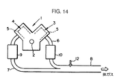
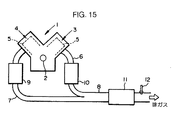
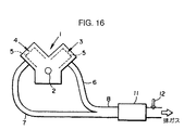
例えば、図14〜図16にそれぞれ示すV型エンジン1では、その出力軸2(クランク軸)の両側に二組の気筒群3,4を有しており、各組の気筒群3,4はそれぞれ互いに近接して出力軸2の軸心方向に並設された複数の気筒5(V型6気筒エンジンでは三個の気筒、V型8気筒エンジンでは四個の気筒)により構成されている。この場合、各気筒群3,4に属する気筒5の個数は、例えばV型6気筒エンジンでは三個、V型8気筒エンジンでは四個である。そして、このV型エンジン1の排気系では、気筒群3に属する気筒5で生成される排ガスをその気筒群の近傍で合流してなる排ガスが排出される副排気管6(副排気通路)が気筒群3から導出されると共に、これと同様に気筒群4に対応する副排気管7(副排気通路)が該気筒群4から導出される。さらに、これらの副排気管6,7の下流端が主排気通路である主排気管8に合流される。
【0004】
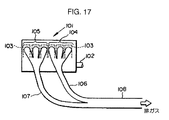
また、例えば図17に示す直列6気筒エンジン101では、その出力軸102(クランク軸)の軸心方向に並設された六個の気筒103が、図の左半分の互いに近接した三個の気筒103からなる気筒群104と、右半分の互いに近接した三個の気筒103からなる気筒群105とにグループ分けされる。そして、このエンジン101の排気系では、それらの気筒群104,105から、前記V型6気筒エンジン1の場合と同様に、それぞれ副排気管(副排気通路)106,107が導出される。さらに、これらの副排気管106,107の下流端が主排気管(主排気通路)108に合流される。
【0005】
また、上記のように複数の気筒群毎の副排気通路と、それらを合流させた主排気通路とを排気系に有する多気筒内燃機関にあっては、三元触媒等により構成される排ガス浄化用の触媒装置は一般に、次のようなレイアウトで設けられている。
【0006】
すなわち、図14に例示する如く各副排気管6,7と主排気管8とにそれぞれ触媒装置9,10,11を介装する場合や、図15に例示する如く各副排気管6,7にそれぞれ触媒装置9,10を介装する場合、図16に例示する如く主排気管8のみに触媒装置11を介装する場合がある。
【0007】
尚、このような触媒装置のレイアウト構成は、図14〜図16のV型エンジン1の排気系に限らず、図17の直列6気筒エンジン101等の排気系についても同様である。
【0008】
一方、上記のような多気筒内燃機関に限らず、内燃機関の排ガス浄化システムでは、触媒装置による排ガスの所要の浄化性能を確実に確保することが従来より重要な課題となっている。
【0009】
そして、このような課題の基で、本願出願人は、触媒装置の所要の浄化性能を該触媒装置の劣化等によらずに確保するために、触媒装置を通過した排ガス中の特定成分の濃度、例えば酸素濃度を検出するO2センサを触媒装置の下流側に設け、このO2センサの出力(酸素濃度の検出値)を所定の目標値(一定値)に収束させるように内燃機関で燃焼させる燃料及び空気の混合気の空燃比を操作する技術を先に提案している(例えば特開平11−93741号公報)。
【0010】
この場合、この技術では、例えば直列4気筒エンジンの排気系のように、全ての気筒の排ガスがエンジンの近傍で単一の排気管に合流され、その単一の排気管にのみ触媒装置が設けられているような排気系に対し、触媒装置の下流側にO2センサを配置している。そして、このO2センサの出力を前記所定の目標値に収束させるようにエンジンで燃焼させる混合気の目標空燃比(より正確にはエンジンの各気筒の排ガスが合流した箇所での排ガスの酸素濃度により表される空燃比の目標値で、各気筒について共通的なもの)を決定し、その目標空燃比に従ってエンジンの各気筒で燃焼させる混合気の空燃比を操作している。
【0011】
このような技術的背景から、前述のように複数の気筒群毎に副排気通路を備えた多気筒内燃機関の排気系にあっては、その各副排気通路や主排気通路に設けた触媒装置の所要の浄化性能を確保するために内燃機関の空燃比を制御するシステムとして、例えば次のようなシステムが考えられる。
【0012】
すなわち、前記図14のように各副排気管6,7と主排気管8とにそれぞれ触媒装置9,10,11を介装した場合にあっては、それらの触媒装置9〜11のトータル的な浄化性能を確保するために、主排気管8の触媒装置11の下流側で該主排気管8にO2センサ12を設け、このO2センサ12の出力を前記所定の目標値に収束させるようにエンジン1の各気筒群4,5で燃焼させる混合気の空燃比を操作する。
【0013】
また、図15のように各副排気管6,7にそれぞれ触媒装置9,10を介装した場合にあっては、これらの触媒装置9,10のトータル的な浄化性能を確保するために、副排気管6,7が合流する主排気管8の上流端近傍にO2センサ12を設け、このO2センサ12の出力を前記所定の目標値に収束させるようにエンジン1の各気筒群4,5で燃焼させる混合気の空燃比を操作する。
【0014】
さらに、図16のように主排気管8のみに触媒装置11を介装した場合にあっては、この触媒装置11の浄化性能を確保するために、該触媒装置11の下流側で主排気管8にO2センサ12を設け、このO2センサ12の出力を前記所定の目標値に収束させるようにエンジン1の各気筒群4,5で燃焼させる混合気の空燃比を操作する。
【0015】
この場合、各気筒群4,5に対応する副排気管7,8の長さや形状の違い、あるいは各副排気管7,8に介装した触媒装置9,10の特性違い等に起因して、一般には、各気筒群4,5で燃焼する混合気の空燃比の変化に対するO2センサ12の出力の変化の応答特性は、副排気管7側と副排気管8側とでは相違する。
【0016】
従って、O2センサ12の出力の前記所定の目標値への収束制御をできるだけ高い安定性と高い速応性で良好に行なうためには、各気筒群4,5毎に各別の目標空燃比を決定し、その目標空燃比に従って各気筒群4,5で燃焼させる混合気の空燃比を操作することが望ましいと考えられる。
【0017】
しかるに、このように各気筒群4,5毎に、目標空燃比を決定するためには、副排気管7,8や、これらに介装する触媒装置9,10を含めたO2センサ12の上流側の排気系を、各気筒群4,5でそれぞれ燃焼させた混合気の空燃比からO2センサ12の出力を生成する2入力1出力の系として把握しなければならない。このため、各気筒群4,5毎の目標空燃比を決定するために、上記の系に対する複雑で煩雑なモデルや演算アルゴリズムが必要となる。また、モデルや演算アルゴリズムが複雑化することで、かえって、モデル化誤差や演算誤差の蓄積も生じやすく、適正な目標空燃比を決定することができなくなる虞れがある。
【0018】
【発明が解決しようとする課題】
本発明はかかる背景に鑑みてなされたものであり、複雑なモデルやアルゴリズムを必要とせずに比較的簡略な手法で、触媒装置の下流側で主排気通路に設けたO2センサ等の排ガスセンサの出力を所定の目標値に収束させるための各気筒群の目標空燃比を適正に決定することができる多気筒内燃機関の空燃比制御装置を提供することを目的とする。
【0019】
さらに、該排ガスセンサの出力の目標値への収束制御を精度よく安定して行なうことができる多気筒内燃機関の空燃比制御装置を提供することを目的とする。
【0020】
【課題を解決するための手段】
本発明の多気筒内燃機関の空燃比制御装置は、かかる目的を達成するために、多気筒内燃機関の全気筒をグループ分けしてなる複数の気筒群にそれぞれ対応して設けられ、対応する気筒群から燃料及び空気の混合気の燃焼により生成された排ガスがそれぞれ排出される複数の副排気通路と、該複数の副排気通路をその下流側で合流してなる主排気通路と、該主排気通路を流れる排ガス中の特定成分の濃度を検出すべく該主排気通路に設けられた排ガスセンサと、該排ガスセンサの上流側で前記各副排気通路及び/又は前記主排気通路に設けられた触媒装置とを排気系に備えた多気筒内燃機関に対し、前記排ガスセンサの出力を所定の目標値に収束させるように各気筒群で燃焼させる混合気の目標空燃比を表す目標空燃比データを逐次生成する目標空燃比デーア生成手段と、該目標空燃比データに応じて前記各気筒群で燃焼させる混合気の空燃比を操作する空燃比操作手段と、前記排気系のうちの前記排ガスセンサの上流側の部分であって前記複数の副排気通路及び触媒装置を含む対象排気系と前記空燃比操作手段と多気筒内燃機関とからなる系が、前記各気筒群に対する目標空燃比の値を全ての気筒群について混ざりモデル形式のフィルタリング処理により合成したものとして定めた目標合成空燃比から前記排ガスセンサの出力を生成する系と等価であるとし、当該等価な系を制御対象系として前記排ガスセンサの出力を前記所定の目標値に収束させるために要求される前記目標合成空燃を表す目標合成空燃比データを逐次生成する目標合成空燃比データ生成手段とを具備し、前記目標空燃比データ生成手段は、前記各気筒群で燃焼させる混合気の目標空燃比を各気筒群について共通として、前記混ざりモデル形式のフィルタリング処理の特性に基づき定まる所定の変換処理により、前記目標合成空燃比データ生成手段が生成した目標合成空燃比データから前記目標空燃比データを逐次生成することを特徴とする(請求項1記載の発明)。実施形態実施形態 かかる本発明によれば、前記各気筒群で燃焼させる混合気の目標空燃比の値を全ての気筒群について混ざりモデル形式のフィルタリング処理により合成したものとして定めた目標合成空燃比を導入することで、前記排気系のうちの前記排ガスセンサの上流側の部分であって前記複数の副排気通路及び触媒装置を含む対象排気系と前記空燃比操作手段と多気筒内燃機関とからなる系(以下の本発明の説明では、この系を実対象系という)を、該目標合成空燃比から前記排ガスセンサの出力を生成する系(前記制御対象系)と等価であるとみなすことができる。つまり、前記実対象系は、前記目標合成空燃比のみを入力量とし、且つ、前記排ガスセンサの出力のみを出力量とする1入力1出力の系と等価であるとみなすことができる。
【0021】
このように前記実対象系と等価な系を導入したとき、その等価な系の出力量である前記排ガスセンサの出力を前記所定の目標値に制御するためには、前記目標合成空燃比を制御対象系に対する制御入力として操作してやればよい。そこで、本発明では、前記目標合成空燃比データ生成手段は、前記実対象系と等価な系を制御対象系として、排ガスセンサの出力を前記所定の目標値に収束させるために要求される前記目標合成空燃比を表す目標合成空燃比データを逐次生成する。
【0022】
この場合、目標合成空燃比データ生成手段は、前記制御対象系に対する単一の制御入力として、目標合成空燃比データのみを生成すればよい。従って、制御対象系の複雑なモデル等を用いることなく、比較的簡素なフィードバック制御のアルゴリズム(例えばPID制御等)を用いて目標合成空燃比データを生成することができる。
【0023】
尚、目標合成空燃比データ生成手段が生成する目標合成空燃比データは、目標合成空燃比の値そのものでよいことはもちろんであるが、例えば、目標合成空燃比の値と所定の基準空燃比(例えば理論空燃比)との偏差であってもよい。
【0024】
また、前記のように目標合成空燃比を定義したとき、前記混ざりモデル形式のフィルタリング処理の特性によって、各気筒群に対する目標空燃比を全ての気筒群について共通のものとすることができる。従って、目標合成空燃比の値が定まれば、上記フィルタリング処理の逆変換的な処理によって、該目標合成空燃比から各気筒群に対する目標空燃比を決定することができる。
【0025】
そこで、本発明では、前記目標空燃比データ生成手段は、前記各気筒群で燃焼させる混合気の目標空燃比を各気筒群について共通として、前記混ざりモデル形式のフィルタリング処理の特性に基づき定まる所定の変換処理(該フィルタリング処理の逆変換的な処理)により、前記目標合成空燃比データ生成手段が生成した目標合成空燃比データから前記目標空燃比データを逐次生成する。
【0026】
これにより、排ガスセンサの出力を前記所定の目標値に収束させるために要求される各気筒群の目標空燃比を得ることができる。
【0027】
尚、前記目標空燃比データは、目標合成空燃比データと同様、目標空燃比の値そのものでよいことはもちろんであるが、例えば、目標空燃比の値と所定の基準空燃比(例えば理論空燃比)との偏差であってもよい。
【0028】
そして、本発明では、前記空燃比操作手段は、上記のように目標空燃比データが生成する目標空燃比データに応じて各気筒群で燃焼させる混合気の空燃比を操作する。これにより、各気筒群で燃焼させる空燃比を排ガスセンサの出力が所定の目標値に収束するように操作することが可能となる。
【0029】
このように本発明によれば、複雑なモデルやアルゴリズムを必要とせずに比較的簡略な手法で、触媒装置の下流側の排ガスセンサの出力を所定の目標値に収束させるための各気筒群の目標空燃比を適正に決定することができる。そして、その目標空燃比に応じて各気筒群の空燃比を操作することで、排ガスセンサの出力の所定の目標値への収束制御を的確に行なうことができる。その結果、排ガスセンサの上流側で前記各副排気通路や主排気通路に設けた触媒装置による所要の浄化性能を確保することができる。
【0030】
尚、本発明において、排ガスセンサの上流側の触媒装置の最適な浄化性能を確保する上では、該排ガスセンサをO2センサとし、該排ガスセンサの出力の目標値を所定の一定値とすることが好適である。
【0031】
かかる本発明において、前記混ざりモデル形式のフィルタリング処理は、例えば所定の制御サイクル毎の前記目標合成空燃比を、当該制御サイクル以前の制御サイクルにおける前記各気筒群の目標空燃比の複数の時系列値を成分とする線形関数により該複数の時系列値を合成して得るフィルタリング処理である(請求項2記載の発明)。
【0032】
このように線形関数を用いたフィルタリング処理によって各気筒群の目標空燃比を決定する上で適正な目標合成空燃比を定義することができる。
【0033】
尚、前記各気筒群の目標空燃比の複数の時系列値を成分とする線形関数は、例えば該複数の時系列値の線形結合である。この場合、前記フィルタリング処理は、当該複数の時系列値の重み付け平均値を前記目標合成空燃比として得る処理となる。
【0034】
上記のように混ざりモデル形式のフィルタリング処理を前記線形関数により定めたとき、所定の制御サイクル毎の前記目標合成空燃比データが、前記線形関数の成分として当該制御サイクル以前の前記目標空燃比データの時系列データを用いてなる線形関数により得られることとなるので、前記目標空燃比データ生成手段は、前記線形関数により定まる所定の演算処理により、前記目標合成空燃比データ生成手段が生成した目標合成空燃比データから所定の制御サイクル毎の前記目標空燃比データを生成することができる(請求項3記載の発明)。
【0035】
この場合、制御サイクル毎の目標空燃比データは、より詳しくは、その制御サイクルにおける目標合成空燃比データと、その制御サイクルよりも過去の制御サイクルにおける目標空燃比データとを用いて求めることができる。
【0036】
また、このような本発明では、前記空燃比操作手段は、前記目標空燃比データ生成した目標空燃比データに対して、フィードフォワード制御により前記各気筒群で燃焼させる混合気の空燃比を操作する(請求項4)。
【0037】
これにより各気筒群で燃焼した混合気の空燃比を検出するためのセンサ等を使用することなく、簡単な手法で、排ガスセンサの出力を前記所定の目標値に収束させるように各気筒群で燃焼させる混合気の空燃比を操作することができる。そして、この場合、各気筒群における実際の空燃比と前記目標空燃比データが表す目標空燃比との誤差の影響は、前記目標合成空燃比データ生成手段が生成する目標合成空燃比データによって吸収することができる。
【0038】
本発明において、前記目標合成空燃比データは、例えばPID制御のように制御対象のモデルを必要としないフィードバック制御手法を用いて生成することも可能である。但し、前記実対象系が多気筒内燃機関や触媒装置等を含むために、該実対象系と等価な前記制御対象系の入力量の変化に対して、該制御対象系の出力量としての前記排ガスセンサの出力の変化は、前記多気筒内燃機関や触媒装置等に起因した応答遅れの影響を受け易い。
【0039】
このため、本発明では、前記制御対象系が前記目標合成空燃比データから少なくとも応答遅れを有して前記排ガスセンサの出力を表すデータを生成する系であるとしてあらかじめ定めた該制御対象系のモデルに基づき構築されたフィードバック制御のアルゴリズムを用いて前記排ガスセンサの出力を前記所定の目標値に収束させるように前記目標合成空燃比データを生成する(請求項5記載の発明)。
【0040】
このように前記制御対象系の応答遅れ特性を考慮した該制御対象系のモデルに基づき構築したフィードバック制御のアルゴリズムを用いて前記目標合成空燃比データを生成することで、前記実対象系が含む多気筒内燃機関や触媒装置等に起因した応答遅れの影響を適正に補償して、排ガスセンサの出力を前記所定の目標値に収束させる上で的確な目標合成空燃比データを生成することができる。また、このとき、前記制御対象系は1入力1出力の系であるので、この制御対象系のモデルも簡略な構成で構築することができる。
【0041】
尚、前記モデルにおいて、前記目標合成空燃比データを、例えば実際の目標合成空燃比と所定の基準空燃比との偏差とし、前記排ガスセンサの出力を表すデータを、例えば該排ガスセンサの実際の出力と前記所定の目標値との偏差とすることが、前記フィードバック制御のアルゴリズムの構築の利便性や、そのアルゴリズムを用いて生成する目標合成空燃比データの信頼性の向上の点で好ましい。
【0042】
上記のように前記目標合成空燃比データ生成手段が目標合成空燃比データを生成するために実行するフィードバック制御のアルゴリズムを制御対象系のモデルに基づき構築したものとするとき、そのフィードバック制御のアルゴリズムは、スライディングモード制御のアルゴリズムであることが好適である(請求項6記載の発明)。
【0043】
そして、特に、前記スライディングモード制御は、適応スラディングモード制御であることが好適である(請求項7記載の発明)。
【0044】
すなわち、スライディングモード制御は、一般に外乱等に対する制御の安定性が高いという特性を有している。従って、このようなスライディングモード制御のアルゴリズムを用いて前記目標合成空燃比データを生成することで、該目標合成空燃比データの信頼性を高め、ひいては、排ガスセンサの出力の目標値への収束制御の安定性を高めることができる。
【0045】
特に、適応スライディングモード制御は、外乱等の影響を極力排除するために、通常のスライディングモード制御に対して、所謂適応則(適応アルゴリズム)といわれる制御則を加味したものである。このため、前記目標合成空燃比データの信頼性をより高めることができる。
【0046】
さらに詳しくいえば、スライディングモード制御では、制御量(本発明では排ガスセンサの出力)とその目標値との偏差等を用いて構成される切換関数といわれる関数が用いられ、この切換関数の値を「0」に収束させることが重要となる。この場合、通常のスライディングモード制御では、切換関数の値を「0」に収束させるために所謂、到達則という制御則が用いられる。しかるに、外乱等の影響を受けると、この到達則だけでは、切換関数の値の「0」への収束の安定性を十分に確保することが困難となる場合もある。これに対して、適応スライディングモード制御は、外乱等の影響を極力排除して切換関数の値を「0」に収束させるために上記到達則に加えて、適応則(適応アルゴリズム)という制御則をも用いるようにしたものである。このような適応スライディングモード制御のアルゴリズムを用いることで、切換関数の値を高い安定性で「0」に収束させ、ひいては排ガスセンサの出力を前記所定の目標値に高い安定性で収束させ得るように目標合成空燃比データを生成することができる。
【0047】
このように前記フィードバック制御のアルゴリズムをスライディングモード制御(適応スライディングモード制御を含む)のアルゴリズムとした本発明では、前記スライディングモード制御のアルゴリズムは、スライディングモード制御用の切換関数として、前記排ガスセンサの出力と前記所定の目標値との偏差の複数の時系列データを成分とする線形関数を用いることが好ましい(請求項8記載の発明)。
【0048】
すなわち、スライディングモード制御では、それに使用する切換関数は、通常、制御量とその変化速度とを用いて構成されるが、該変化速度は一般に直接的に検出することが困難で、制御量の検出値から算出することとなる場合が多い。そして、このとき、該制御量の変化速度の値には、誤差が生じやすい。
【0049】
これに対して、本発明では、スライディングモード制御用の切換関数を排ガスセンサの出力と前記所定の目標値との偏差の複数の時系列データを成分とする線形関数により構成するため、排ガスセンサの出力の変化速度を必要とすることなく、目標合成空燃比データを生成するためのアルゴリズムを構築することができる。このため、生成する目標合成空燃比データの信頼性を高めることができる。
【0050】
尚、このように切換関数を構成したとき、スライディングモード制御のアルゴリズムは、排ガスセンサの出力と前記所定の目標値との偏差の複数の時系列データの各値を「0」に収束させるように目標合成空燃比データを生成することとなる。
【0051】
また、前述のように目標合成空燃比データを生成するために、前記スライディングモード制御のアルゴリズムを含めて前記制御対象系のモデルに基づくフィードバック制御のアルゴリズムを用いる本発明では、前記モデルは、前記制御対象系の挙動を連続時間系で表現するモデルとしてもよいが、前記制御対象系の挙動を離散時間系で表現したモデルであることが好ましい(請求項9記載の発明)。
【0052】
このようにすることで、前記フィードバック制御のアルゴリズムの構築がより容易になると共に、そのアルゴリズムをコンピュータ処理に適したものとすることができる。
【0053】
この場合、前記制御対象系の挙動を離散時間系で表現するモデルは、例えば、所定の制御サイクル毎の前記排ガスセンサの出力を表すデータを、当該制御サイクルよりも過去の制御サイクルにおける排ガスセンサの出力を表すデータと前記目標合成空燃比データとにより表現するモデルである(請求項10記載の発明)。
【0054】
このように前記モデルを構成することで、前記制御対象系の挙動を該モデルにより適正に表現することができる。
【0055】
尚、この場合、前記過去の制御サイクルにおける排ガスセンサの出力を表すデータは、所謂、自己回帰項で、前記制御対象系が有する応答遅れに係わるものとなる。
【0056】
上述のように前記制御対象系のモデルを離散時間系のモデルとした本発明では、前記目標合成空燃比データ生成手段が過去に生成した目標合成空燃比データと前記排ガスセンサの出力を表すデータとを用いて前記モデルの設定すべきパラメータの値を逐次同定する同定手段とを備え、前記目標合成空燃比データ生成手段が実行する前記フィードバック制御のアルゴリズムは、前記同定手段が同定した前記パラメータの値を用いて新たな前記目標合成空燃比データを生成するアルゴリズムであることが好ましい(請求項11記載の発明)。
【0057】
すなわち、前記モデルは、その挙動を規定する上である値に設定すべきパラメータを有する。例えば前記モデルが、前述のように所定の制御サイクル毎の前記排ガスセンサの出力を表すデータを、当該制御サイクルよりも過去の制御サイクルにおける排ガスセンサの出力を表すデータと前記目標合成空燃比データとにより表現するモデルとしたときには、前記過去の制御サイクルにおける排ガスセンサの出力を表すデータと前記目標合成空燃比データとにそれぞれ係る係数パラメータを該モデルのパラメータとして含む。
【0058】
そして、そのモデルに基づき構築される前記フィードバック制御のアルゴリズムでは、該モデルのパラメータを用いて前記目標合成空燃比データを生成すこととなる。このため、該目標合成空燃比データの信頼性をより高める上では、該モデルのパラメータの値を前記制御対象系の実際の挙動(これは前記実対象系の実際の挙動特性に基づくもので、経時的に変化することが多い)に則してリアルタイムで同定することが好ましい。
【0059】
また、前記制御対象系を離散時間系で表現する前記モデルでは、前記目標合成空燃比データ生成手段が過去に生成した目標合成空燃比データと、前記排ガスセンサの出力を表すデータとを用いることで、前記モデルのパラメータを、制御対象系の実際の挙動に即して逐次同定することができる。
【0060】
このようなことから、本発明では、前記同定手段を備えて、前記モデルのパラメータの値を逐次同定し、その同定したパラメータの値を用いて目標合成空燃比データを生成する。これにより、前記実対象系の時々刻々の実際の挙動に基づく前記制御対象系の実際の挙動に即して、前記目標合成空燃比データを生成することが可能となる。この結果、該目標合成空燃比データの信頼性をより高め、排ガスセンサの出力の前記所定の目標値への収束制御を精度よく安定して行なうことができる。
【0061】
尚、前記モデルが、前述のように所定の制御サイクル毎の前記排ガスセンサの出力を表すデータを、当該制御サイクルよりも過去の制御サイクルにおける排ガスセンサの出力を表すデータと前記目標合成空燃比データとにより表現するモデルであるときには、前記同定手段により同定するパラメータは、前記排ガスセンサの出力を表すデータ及び前記目標合成空燃比データにそれぞれ係る係数パラメータのうちの少なくとも一つ(好ましくは全ての係数パラメータ)である。
【0062】
また、前記同定手段は、前記モデル上での前記排ガスセンサの出力と該排ガスセンサの実際の出力との間の誤差を最小化するように構築されたアルゴリズム(例えば最小二乗法、重み付き最小二乗法、固定ゲイン法、漸減ゲイン法、固定トレース法等の同定アルゴリズム)により前記パラメータの値を逐次同定することができる。
【0063】
また、上述のような同定手段を有する本発明において、前記空燃比操作手段は、常に前記目標空燃比データ生成手段が目標合成空燃比データから生成する目標空燃比データにより表される目標空燃比に従って、各気筒群における混合気の空燃比を操作しなけらばならないわけではなく、多気筒内燃機関の運転状態(例えば該内燃機関のフュエルカット運転時や大出力が要求される運転時等)によっては、必要に応じて、前記目標空燃比データ生成手段が生成した目標空燃比データ以外の目標空燃比に応じて、各気筒群における空燃比を操作するようにしてもよい。
【0064】
そして、このように前記空燃比操作手段が、前記多気筒内燃機関の運転状態に応じて、前記目標空燃比データ生成手段が生成した前記目標空燃比データにより表される目標空燃比以外の目標空燃比に応じて前記各気筒群で燃焼させる混合気の空燃比を操作する手段を備えている場合で、前記同定手段を備えた場合においては、該空燃比操作手段が各気筒群における空燃比を操作するために実際に使用した目標空燃比を表すデータに対して前記混ざりモデル形式のフィルタリング処理と同一のフィルタリング処理を施すことにより、当該実際の目標空燃比に対応する目標合成空燃比データとしての実使用目標合成空燃比データを逐次求めるフィルタ手段を備え、前記同定手段は、前記目標合成空燃比データ生成手段が生成した目標合成空燃比データの代わりに前記フィルタ手段が求めた前記実使用目標合成空燃比データを用いて前記モデルのパラメータの値を同定することが好ましい(請求項12記載の発明)
すなわち、前記空燃比操作手段が実際に使用した目標空燃比を表すデータ(これは前記目標空燃比データが生成した目標空燃比データとは限らない)に対して、前記フィルタ手段により、前記混ざりモデル形式のフィルタリング処理と同一のフィルタリング処理を施すことによって、空燃比操作手段が実際に使用した目標空燃比に対応する目標合成空燃比データとしての、前記実使用目標合成空燃比データが求められる。そして、この実使用目標合成空燃比データを、前記同定手段が前記モデルのパラメータの値を同定するために前記目標合成空燃比データの代わりに用いることで、空燃比操作手段による各気筒群の空燃比の実際の操作状況を考慮した形態で、前記モデルのパラメータの値が同定されることとなる。
【0065】
従って、同定手段が同定する前記モデルのパラメータの値には、空燃比操作手段による各気筒群の空燃比の実際の操作状況が反映されることとなる。その結果、該モデルのパラメータの同定値の信頼性を高めることができる。
【0066】
一方、本発明の多気筒内燃機関の空燃比制御装置において、前記実対象系に含まれる前記多気筒内燃機関や触媒装置、各副排気管(これは比較的長い)の影響で、前記制御対象系が比較的長い無駄時間(制御対象系の入力量である目標合成空燃比の各時点における値が排ガスセンサの出力に反映されるようになるまでに要する時間)を有するものとなることがある。そして、このような無駄時間が制御対象系に存する場合には、該無駄時間を考慮せずに、目標合成空燃比データを生成して、各気筒群の空燃比を操作すると、排ガスセンサの出力の所定の目標値への収束制御の安定性が低下しやすい。
【0067】
そこで、本発明では、前記制御対象系が前記目標合成空燃比データから応答遅れ及び無駄時間を有して前記排ガスセンサの出力を表すデータを生成する系であるとしてあらかじめ定めた該制御対象系のモデルに基づき構築されたアルゴリズムにより前記無駄時間後の前記排ガスセンサの出力の推定値を表すデータを逐次生成する推定手段を備え、前記目標合成空燃比データ生成手段は、該推定手段により生成されたデータを用いて構築されたフィードバック制御のアルゴリズムにより前記排ガスセンサの出力を前記所定の目標値に収束させるように前記目標合成空燃比データを生成する(請求項13記載の発明)。
【0068】
すなわち、上記のように前記制御対象系の応答遅れと無駄時間とを考慮した該制御対象系のモデルを定めておくことで、前記推定手段は、該モデルに基づき構築したアルゴリズムによって、前記無駄時間後の排ガスセンサの出力の推定値を表すデータを逐次生成することができる。
【0069】
そして、前記目標合成空燃比データ生成手段が、その排ガスセンサの出力の推定値を表すデータを用いて構築されたフィードバック制御のアルゴリズムによって、前記目標合成空燃比データを生成することで、前記制御対象系の無駄時間の影響を補償し、排ガスセンサの出力を安定に所定の目標値に収束させる上で適正な目標合成空燃比データを生成することができる。
【0070】
尚、前記推定手段に関する前記制御対象系のモデルにあっては、前記目標合成空燃比データを、例えば実際の目標合成空燃比と所定の基準空燃比との偏差とし、前記排ガスセンサの出力を表すデータを、例えば該排ガスセンサの実際の出力と前記所定の目標値との偏差とする。このようにすると、前記排ガスセンサの出力の推定値を表すデータを生成するためのアルゴリズムの構築の利便性や、そのアルゴリズムを用いて生成する排ガスセンサの出力の推定値を表すデータの信頼性の向上の点で有利である。また、このようにしたとき、前記排ガスセンサの出力の推定値を表すデータは、該排ガスセンサの出力の推定値と、前記所定の目標値との偏差となる。
【0071】
上述のように推定手段を備えた本発明にあっては、前記推定手段が実行するアルゴリズムを、前記排ガスセンサの出力を表すデータと前記目標合成空燃比データ生成手段が過去に生成した前記合成空燃比データとを用いて前記排ガスセンサの出力の推定値を表すデータを生成するアルゴリズムとすることで、前記排ガスセンサの出力の推定値を表すデータを逐次生成することができる(請求項14記載の発明)。
【0072】
そして、この場合、特に、前記空燃比操作手段が、前記多気筒内燃機関の運転状態に応じて、前記目標空燃比データ生成手段が生成した前記目標空燃比データにより表される目標空燃比以外の目標空燃比に応じて前記各気筒群で燃焼させる混合気の空燃比を操作する手段を備えている場合にあっては、前述した請求項12記載の発明に関して説明したこととと同様の理由によって、該空燃比操作手段が各気筒群における空燃比を操作するために実際に使用した目標空燃比を表すデータに対して前記混ざりモデル形式のフィルタリング処理と同一のフィルタリング処理を施すことにより、当該実際の目標空燃比に対応する目標合成空燃比データとしての実使用目標合成空燃比データを逐次求めるフィルタ手段を備え、前記推定手段は、前記目標合成空燃比データ生成手段が生成した目標合成空燃比データの代わりに前記フィルタ手段が求めた前記実使用目標合成空燃比データを用いて前記排ガスセンサの出力の推定値を表すデータを生成することが好ましい(請求項15記載の発明)。
【0073】
このように空燃比操作手段が実際に使用した目標空燃比を表すデータから前記フィルタ手段によって前記実使用目標合成空燃比データを求め、この実使用目標合成空燃比データを、目標合成空燃比データ生成手段が生成した目標合成空燃比データの代わりに用いて排ガスセンサの出力の推定値を表すデータを生成することで、空燃比操作手段による各気筒群の空燃比の実際の操作状況を考慮した形態で、排ガスセンサの出力の推定値を表すデータが生成されることとなる。
【0074】
従って、推定手段が生成する排ガスセンサの出力の推定値を表すデータには、空燃比操作手段による各気筒群の空燃比の実際の操作状況が反映されることとなり、該推定値を表すデータの信頼性を高めることができる。
【0075】
上記のように、推定手段を備えた本発明では、前記制御対象系のモデルを、該系の挙動を連続時間系で表現するモデルとして推定手段のアルゴリズムを構築することも可能であるが、該制御対象系のモデルは、該系の挙動を離散時間系で表現したモデルであることが好ましい(請求項16、17記載の発明)。
【0076】
このようにすることで、前記推定手段が実行するアルゴリズムの構築がより容易になると共に、そのアルゴリズムをコンピュータ処理に適したものとすることができる。
【0077】
上記のように前記制御対象系の挙動を離散時間系で表現する該制御対象系のモデルは、例えば、所定の制御サイクル毎の前記排ガスセンサの出力を表すデータを、当該制御サイクルよりも過去の制御サイクルにおける排ガスセンサの出力を表すデータと、当該制御サイクルよりも前記制御対象系が有する無駄時間以前の制御サイクルにおける前記目標合成空燃比データとにより表現するモデルである(請求項18記載の発明)。
【0078】
このように前記モデルを構成することで、前記制御対象系の挙動をその応答遅れと無駄時間とを含めて該モデルにより適正に表現することができる。
【0079】
尚、この場合、前記過去の制御サイクルにおける排ガスセンサの出力を表すデータは、所謂、自己回帰項で、前記制御対象系が有する応答遅れに係わるものとなる。また、制御対象系の無駄時間以前の前記目標合成空燃比データによって、制御対象系の無駄時間が表現されることとなる。
【0080】
このように制御対象系のモデルを離散時間系で表現した場合においては、前記目標合成空燃比データ生成手段が過去に生成した目標合成空燃比データと前記排ガスセンサの出力を表すデータとを用いて前記制御対象系のモデルの設定すべきパラメータの値を逐次同定する同定手段を備え、前記推定手段が実行するアルゴリズムは前記排ガスセンサの出力の推定値を表すデータを生成するために前記同定手段が同定した前記パラメータの値を用いるアルゴリズムであることが好ましい(請求項19記載の発明)。
【0081】
そして、特に、前記空燃比操作手段が、前述のように前記目標空燃比データ生成手段が生成した前記目標空燃比データにより表される目標空燃比以外の目標空燃比に応じて前記各気筒群で燃焼させる混合気の空燃比を操作する手段を備えており、前記推定手段のアルゴリズムが前記目標合成空燃比データの代わりに前記フィルタ手段により逐次求める実使用目標合成空燃比データを用いる場合にあっては、前記フィルタ手段が過去に求めた前記実使用合成空燃比データと前記排ガスセンサの出力を表すデータとを用いて前記制御対象系のモデルの設定すべきパラメータの値を逐次同定する同定手段を備え、前記推定手段が実行するアルゴリズムは前記排ガスセンサの出力の推定値を表すデータを生成するために前記同定手段が同定した前記パラメータの値を用いるアルゴリズムであることが好適である(請求項20記載の発明)。
【0082】
すなわち、前記制御対象系のモデルは、その挙動を規定する上である値に設定すべきパラメータを有する。例えば該モデルを、前述のように所定の制御サイクル毎の前記排ガスセンサの出力を表すデータを、当該制御サイクルよりも過去の制御サイクルにおける排ガスセンサの出力を表すデータと、当該制御サイクルよりも前記制御対象系が有する無駄時間以前の制御サイクルにおける前記目標合成空燃比データとにより表現するモデルとしたときには、前記過去の制御サイクルにおける排ガスセンサの出力を表すデータと前記無駄時間以前の制御サイクルにおける前記目標合成空燃比データとにそれぞれ係る係数パラメータを該モデルのパラメータとして含む。
【0083】
そして、前記推定手段のアルゴリズムは、該制御対象系のモデルに基づくものであるので、該モデルのパラメータを用いて前記排ガスセンサの出力の推定値を表すデータを生成すこととなる。このため、該排ガスセンサの出力の推定値を表すデータの信頼性をより高める上では、該モデルのパラメータの値を前記制御対処系の実際の挙動に則してリアルタイムで同定することが好ましい。
【0084】
また、制御対象系を離散時間系で表現するモデルでは、前記目標合成空燃比データ生成手段が過去に生成した目標合成空燃比データと、前記排ガスセンサの出力を表すデータとを用いることで、該モデルのパラメータを、制御対象系の実際の挙動に即して逐次同定することができる。
【0085】
さらにこのとき、前記実使用目標合成空燃比データを求める前記フィルタ手段を備えた場合にあっては、前記パラメータの値を同定するために、前記目標合成空燃比データの代わりに実使用目標合成空燃比データを用いることが好ましい。
【0086】
このようなことから、前記推定手段を備えた本発明では、前記同定手段によって、前記制御対象系のモデルのパラメータの値を逐次同定し、前記推定手段は、その同定されたパラメータの値を用いて排ガスセンサの出力の推定値を表すデータを逐次生成する。これにより、前記実対象系の時々刻々の実際の挙動に基づく前記制御対象系の実際の挙動に即して、排ガスセンサの出力の推定値を表すデータを生成することが可能となる。この結果、該推定値を表すデータの信頼性をより高めることができる。
【0087】
そして、特に空燃比操作手段が、前記目標空燃比データにより表される目標空燃比以外の目標空燃比に応じて前記各気筒群で燃焼させる混合気の空燃比を操作する手段を備えているときには、同定手段がパラメータの値を同定するために、前記目標合成空燃比データの代わりに前記実使用目標合成空燃比データを用いることで、該パラメータの同定値に、空燃比操作手段による各気筒群の空燃比の実際の操作状況が反映されることとなる。このため、該パラメータの同定値の信頼性が高まり、前記推定手段が生成する排ガスセンサの出力の推定値を表すデータの信頼性をより高めることができる。
【0088】
この結果、該推定値を表すデータを用いて構築された前記フィードバック制御のアルゴリズムによって、信頼性の高い目標合成空燃比データを生成することができ、排ガスセンサの出力の前記所定の目標値への収束制御を精度よく安定して行なうことができる。
【0089】
尚、前記制御対象系のモデルが、前述のように所定の制御サイクル毎の前記排ガスセンサの出力を表すデータを、当該制御サイクルよりも過去の制御サイクルにおける排ガスセンサの出力を表すデータと、当該制御サイクルよりも前記制御対処系が有する無駄時間以前の制御サイクルにおける前記目標合成空燃比データとにより表現するモデルであるときには、前記同定手段により同定するパラメータは、前記排ガスセンサの出力を表すデータ及び前記目標合成空燃比データにそれぞれ係る係数パラメータのうちの少なくとも一つ(好ましくは全ての係数パラメータ)である。
【0090】
また、前記同定手段は、前記制御対象のモデル上での前記排ガスセンサの出力と該排ガスセンサの実際の出力との間の誤差を最小化するように構築されたアルゴリズム(例えば最小二乗法、重み付き最小二乗法、固定ゲイン法、漸減ゲイン法、固定トレース法等の同定アルゴリズム)により前記パラメータの値を逐次同定することができる。
【0091】
上記のように推定手段に加えて同定手段を備えた本発明では、前記目標合成空燃比データを生成するための前記フィードバック制御のアルゴリズムは、例えば前記推定手段における制御対象系のモデルとは別に定めた制御対象系のモデル等に基づいて構築されたものであってもよい。但し、前記目標合成空燃比データ生成手段が実行する前記フィードバック制御のアルゴリズムは、前記制御対象系のモデルに基づき構築され、前記同定手段が同定した前記パラメータの値を用いて前記目標合成空燃比データを生成するアルゴリズムであることが好ましい(請求項21記載の発明)。
【0092】
このように、前記フィードバック制御のアルゴリズムを、前記推定手段のアルゴリズムの構築のために定めた制御対象系のモデルに基づいて構築することで、推定手段が生成する排ガスセンサの出力の推定値を表すデータを用いたフィードバック制御のアルゴリズムの構築が容易となる。同時に、該フィードバック制御のアルゴリズムで、前記同定手段が同定する制御対象系のパラメータの値を用いることで、制御対象系の実際の挙動に即して、前記目標合成空燃比データを生成することができる。すなわち、排ガスセンサの出力を所定の目標値に収束制御する上で、信頼性の高い目標合成空燃比データを生成することができる。
【0093】
また、推定手段を備えた本発明では、前記目標合成空燃比データ生成手段が実行する前記フィードバック制御のアルゴリズムは、前記推定手段が生成したデータにより表される前記排ガスセンサの出力の推定値を前記所定の目標値に収束させるように前記目標合成空燃比データを生成するアルゴリズムである(請求項22記載の発明)。
【0094】
このようなフィードバック制御のアルゴリズムによって、前記制御対象系の無駄時間の影響を適正に補償し、排ガスセンサの出力を所定の目標値に収束させる上で信頼性の高い目標合成空燃比を生成することができる。
【0095】
また、推定手段を備える本発明では、前述した制御対象系のモデルに基づくフィードバック制御のアルゴリズムに関して説明した場合(請求項6,7に関する説明を参照)と同様、前記目標合成空燃比データ生成手段が実行するフィードバック制御のアルゴリズムはスライディングモード制御のアルゴリズムであることが好適である(請求項23記載の発明)。
【0096】
そして、特に、前記スライディングモード制御は、適応スラディングモード制御であることが好適である(請求項24記載の発明)。
【0097】
すなわち、適応スライディングモード制御を含めてスライディングモード制御は、前述した通りの特徴を有するものであるので、このようなスライディングモード制御、特に適応スライディングモード制御のアルゴリズムを用いて前記目標合成空燃比データを生成することで、該目標合成空燃比データの信頼性を高め、ひいては、排ガスセンサの出力の目標値への収束制御の安定性を高めることができる。
【0098】
そして、本発明ではさらに、前記スライディングモード制御のアルゴリズムは、スライディングモード制御用の切換関数として、前記推定手段が生成したデータにより表される前記排ガスセンサの出力の推定値と前記所定の目標値との偏差の複数の時系列データを成分とする線形関数を用いる(請求項25記載の発明)。
【0099】
このようにスライディングモード制御用の切換関数を構成することで、排ガスセンサの出力の変化速度のデータ等を必要とせずに、目標合成空燃比データを生成するためのアルゴリズムを構築することができため、生成する目標合成空燃比データの信頼性を高めることができる。
【0100】
また、このとき、スライディングモード制御のアルゴリズムは、排ガスセンサの出力の推定値と前記所定の目標値との偏差の複数の時系列データの各値を「0」に収束させるように目標合成空燃比データを生成することとなるので、前記制御対象系の無駄時間の影響を適正に補償することができる。
【0101】
【発明の実施の形態】
本発明の一実施形態を図1〜図13を参照して説明する。
【0102】
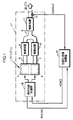
図1を参照して、本実施形態は、例えば前記図15に示した構成の排気系を有する多気筒内燃機関としてのV型エンジン1(以下、単にエンジン1という)の空燃比制御装置に関するものであり、同図1はこの装置の全体的システム構成を示すブロック図である。
【0103】
この場合、図1では便宜上、このエンジン1とその排気系とを図16よりも簡略化して記載している。また、エンジン1は、より具体的には、例えば自動車やハイブリッド車に車両の推進源として搭載されたV型6気筒エンジンであり、その二つの気筒群3,4はそれぞれ三個の気筒(図示せず)により構成されている。
【0104】
エンジン1の排気系は、前記図15に関して説明した如く、エンジン1の二つの気筒群3,4にそれぞれ対応する副排気管6,7(副排気通路)と、これらの副排気管6,7を合流させた主排気管8(主排気通路)と、それらの副排気管6,7及び主排気管8にそれぞれ介装された触媒装置9,10,11とを具備する。各触媒装置9〜11は例えば三元触媒により構成されている。
【0105】
そして、主排気管8には、触媒装置11の下流側で、排ガスセンサとしてのO2センサ12が装着されている。
【0106】
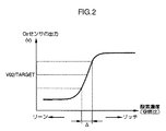
このO2センサ12は、触媒装置11を通過して主排気管8を流れる排ガス中の酸素濃度に応じたレベルの出力VO2/OUT(酸素濃度の検出値を表す出力)を生成する通常的なO2センサである。ここで、排ガス中の酸素濃度は、その排ガスを燃焼により生成した混合気の空燃比に応じたものとなる。そして、このO2センサ12の出力VO2/OUTは、図2に実線aで示す如く、排ガス中の酸素濃度に対応する空燃比が理論空燃比近傍の範囲Δに存するような状態で、該排ガスの酸素濃度にほぼ比例した高感度な変化を生じるものとなる。また、その範囲Δを逸脱した空燃比に対応する酸素濃度では、O2センサ12の出力VO2/OUTは飽和して、ほぼ一定のレベルとなる。
【0107】
本実施形態のシステムは、基本的には、触媒装置9〜11からなる排ガス浄化装置の全体の最適な浄化性能を確保するようにエンジン1の各気筒群3,4で燃焼させる混合気の空燃比を操作する制御を行なうものである。この場合、前記O2センサの出力VO2/OUTを、ある一定の目標値VO2/TARGET(図2を参照)に収束(整定)させるように、エンジン1の各気筒群3,4で燃焼させる混合気の空燃比を操作したとき、各触媒装置9〜11の経時的な劣化等によらずに、これらの触媒装置9〜11からなる排ガス浄化装置の全体の最適な浄化性能を確保することができる。
【0108】
そして、本実施形態のシステムは、このようにO2センサの出力VO2/OUTを一定の目標値VO2/TARGETに収束(整定)させる制御を行なうために、次のような制御器を備えている。
【0109】
すなわち、前記O2センサ12の出力を用いて、各気筒群3,4で燃焼させる混合気の目標空燃比KCMD(詳しくは各気筒群3,4にそれぞれ属する気筒の排ガスを合流してなる排ガスの酸素濃度により把握される各気筒群3,4毎の空燃比の目標値)を所定の制御サイクルで逐次生成する処理を実行する制御器15(以下、空燃比処理制御器15という)と、この空燃比処理制御器15が求めた目標空燃比KCMDに応じて各気筒群3,4に対する燃料供給量(燃料噴射量)を調整する処理を所定の制御サイクルで実行することで、各気筒群3,4で燃焼させる混合気の空燃比を上記目標空燃比KCMDに操作する空燃比操作手段としての制御器16(以下、燃料供給制御器16という)とを備えている。
【0110】
尚、燃料供給制御器16には、O2センサ12の出力VO2/OUTや、エンジン1の回転数、吸気圧(吸気管内圧)、冷却水温等を検出するための図示しない各種センサの出力も与えられるようになっている。また、空燃比処理制御器15と燃料供給制御器16とは、前記目標空燃比KCMDのデータの他、各種の作動状態情報を相互に授受できるようになっている。
【0111】
これらの制御器15,16はマイクロコンピュータを用いて構成されたもので、それぞれの制御処理を所定の制御サイクルで実行する。ここで、本実施形態では、空燃比処理制御器15がその制御処理(目標空燃比KCMDの生成処理)を実行する制御サイクルは、触媒装置9〜11等に起因した後述の無駄時間や、演算負荷等を考慮して、あらかじめ定めた一定周期(例えば30〜100ms)としている。
【0112】
また、燃料供給制御器16が実行する制御処理(燃料噴射量の調整処理)は、エンジン1の回転数(詳しくはエンジン1の燃焼サイクル)に同期させて行なう必要がある。このため、該燃料供給制御器16がその制御処理を実行する制御サイクルは、エンジン1のクランク角周期(所謂TDC)に同期した周期としている。
【0113】
尚、空燃比処理制御器15の制御サイクルの一定周期は、前記クランク角周期(TDC)よりも長いものとされている。
【0114】
前記空燃比処理制御器15及び燃料供給制御器16のそれぞれの制御処理についてさらに説明する。
【0115】
まず、前記空燃比処理制御器15は、エンジン1の排気系のうちの、エンジン1側からO2センサ12にかけての部分(O2センサ12よりも上流側の部分で副排気管6,7や触媒装置9〜11を含む部分)と、エンジン1及び前記燃料供給制御器16とを合わせた系(図1の参照符号17を付した系。以下、対象系17という)の応答遅れ特性や無駄時間等の挙動特性を考慮しつつ、O2センサ12の出力VO2/OUTを前記目標値VO2/TARGETに収束させるように、各気筒群3,4に対する目標空燃比KCMDを所定の制御サイクル(一定周期)で逐次求める処理を行なうものである。
【0116】
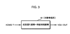
この処理を行なうために、本実施形態では、上記対象系17が、各気筒群3,4に対する目標空燃比KCMDを、後述するフィルタリング処理によって両気筒群3,4について合成したものとして定めた目標合成空燃比(以下、これに参照符号KCMD/Tを付する)から、応答遅れと無駄時間とを有してO2センサ12の出力VO2/OUTを生成する系と等価であるとみなす。
【0117】
つまり、前記対象系17は、図3に示す如く、目標合成空燃比KCMD/Tを入力量、O2センサ12の出力VO2/OUTを出力量とする1入力1出力の系18と等価であって、その等価な系18(以下、対象等価系18という)が応答遅れ要素と無駄時間要素とからなる系であるとする。
【0118】
ここで、上記対象等価系18の応答遅れ要素は、主として、前記対象系17が有するエンジン1及び触媒装置9〜11に起因するものである。また、対象等価系18の無駄時間要素は、主として、対象系17が有するエンジン1、副排気管6,7及び触媒装置9〜11に起因するものである。
【0119】
前記空燃比処理制御器15が実行する基本的な制御処理では、この対象等価系18を制御対象系としたフィードバック制御のアルゴリズムによって、該対象等価系18の出力量であるO2センサ12の出力VO2/OUTをその目標値VO2/TARGETに収束させるように、該対象等価系18に対する制御入力としての目標合成空燃比KCMD/Tを制御サイクル毎に逐次求める。さらに、この目標合成空燃比KCMD/Tから、各気筒群3,4に対する目標空燃比KCMDを求める。尚、各気筒群3,4に対する目標空燃比KCMDは本実施形態では、両気筒群3,4について共通であるが、以下の説明では、しばらくの間、それらを区別し、各気筒群3,4に対する目標空燃比をそれぞれ参照符号KCMD/A,KCMD/Bを付して表す。
【0120】
本実施形態では、上記のような制御処理を実行するために、前記対象等価系18の挙動を表現するモデルをあらかじめ構築しておく。この場合、このモデルの構築にあたっては、対象等価系18の入力量として、前記目標合成空燃比KCMD/Tとあらかじめ定めた所定の基準空燃比FLAF/BASEとの偏差(=KCMD/T−FLAF/BASE。以下、目標合成偏差空燃比kcmd/tという)を用いる。さらに、対象等価系18の出力量として、O2センサ12の出力VO2/OUTとこれに対する前記目標値VO2/TARGETとの偏差(=VO2/OUT−VO2/TARGET。以下、偏差出力VO2という)を用いる。
【0121】
尚、上記基準空燃比FLAF/BASEは、本実施形態では例えば「理論空燃比」としている。また、本発明の構成に対応させると、前記目標合成偏差空燃比kcmd/tは、目標合成空燃比データに相当するものであり、O2センサ12の偏差出力VO2はO2センサ12の出力を表すデータに相当するものである。
【0122】
本実施形態では、これらの目標合成偏差空燃比kcmd/tとO2センサ12の偏差出力VO2とにより次のように対象等価系18のモデルを構築している。
【0123】
すなわち、この対象等価系18のモデルは、次式(1)の如く、該対象等価系18の挙動を離散時間系で表現するモデル(より詳しくは対象等価系18の入力量としての目標合成偏差空燃比kcmd/tに無駄時間を有する自己回帰モデル)として構築する。
【0124】
【数1】

ここで、上式(1)において、「k」は空燃比処理制御器15の離散時間的な制御サイクルの番数を表す整数である(以下、同様)。また、「d」は対象等価系18が有する無駄時間、すなわち、各制御サイクルにおける目標合成空燃比KCMD/Tもしくは目標合成偏差空燃比kcmd/tの値がO2センサ12の出力VO2/OUTもしくは偏差出力VO2に反映されるようになるまでに要する無駄時間を空燃比処理制御器15の制御サイクル数で表したものである。この無駄時間dの値は、後述するようにあらかじめ定めた所定値(固定値)に設定されるものである。
【0126】
また、式(1)の右辺第1項及び第2項はそれぞれ対象等価系18の応答遅れ要素を表す自己回帰項である。そして、「a1」、「a2」はそれぞれ1次目の自己回帰項のゲイン係数、2次目の自己回帰項のゲイン係数である。これらのゲイン係数a1,a2は別の言い方をすれば、対象等価系18の出力量としてのO2センサ12の偏差出力VO2に係る係数パラメータである。
【0127】
さらに、式(1)の右辺第3項は、対象等価系18の無駄時間要素を表すものであり、より正確には、対象等価系18の入力量としての目標合成偏差空燃比kcmd/tに対象等価系18の無駄時間dを含めて表現したものである。そして、「b1」はこの要素に係るゲイン係数であり、別の言い方をすれば、対象等価系18の入力量としての目標合成偏差空燃比kcmdに係る係数パラメータである。
【0128】
これらのゲイン係数a1,a2,b1は、対象等価系18のモデルの挙動を規定する上で、ある値に設定(同定)すべきパラメータであり、本実施形態では後述の同定器によって逐次同定されるものである。
【0129】
このように式(1)により離散時間系で表現した対象等価系18のモデルは、それを言葉で表現すれば、空燃比処理制御器15の各制御サイクルにおける対象等価系18の出力量としてのO2センサ12の偏差出力VO2(k+1)を、その制御サイクルよりも過去の制御サイクルにおける複数(本実施形態では二つ)の偏差出力VO2(k),VO2(k-1)と、対象等価系18の無駄時間d以前の制御サイクルにおけるおける対象等価系18の入力量としての目標合成偏差空燃比kcmd/t(k-d)とにより表したものである。
【0130】
一方、上記のような対象等価系18の入力量である目標合成空燃比KCMD/Tは、本実施形態では、各気筒群3,4に対する目標空燃比KCMD/A,KCMD/Bを、以下に説明する混ざりモデル形式のフィルタリング処理によって両気筒群3,4について合成したものとして定義している。この場合、前記対象等価系18のモデルにおいて目標合成偏差空燃比kcmd/t(=KCMD/T−FLAF/BASE)を用いることから、この目標合成偏差空燃比kcmd/tを、気筒群3に対する目標空燃比KCMD/Aと前記基準空燃比FLAF/BASEとの偏差kcmd/a(=KC MD/A−FLAF/BASE。以下、目標偏差空燃比kcmd/aという)と、気筒群4に対する目標空燃比KCMD/Bと基準空燃比との偏差FLAF/BASEとの偏差kcmd/b(=KCMD/B−FLAF/BASE。以下、目標偏差空燃比kcmd/bという)とを合成したものとして定義する。
【0131】
すなわち、本実施形態では、目標合成偏差空燃比kcmd/tは、各気筒群3,4に対する目標偏差空燃比kcmd/a,kcmd/bを、次式(2)により表す混ざりモデル形式のフィルタリング処理によって合成したものとして定義する。
【0132】
【数2】
ここで、式(2)の右辺に現れる「dA」は、空燃比処理制御器15の各制御サイクルにおける気筒群3側の目標空燃比KCMD/Aが気筒群3や副排気管6等を介してO2センサ12の出力VO2/OUTに反映されるようになるまでに要する無駄時間(以下、気筒群3側無駄時間という)を空燃比処理制御器15の制御サイクル数で表したものである。また、「dB」は、各制御サイクルにおける気筒群4側の目標空燃比KCMD/Bが気筒群4や副排気管7等を介してO2センサ12の出力VO2/OUTに反映されるようになるまでに要する無駄時間(以下、気筒群4側無駄時間という)を空燃比処理制御器15の制御サイクル数で表したものである。
【0134】
これらの無駄時間dA,dBの値は、各気筒群3,4の動作特性、各副排気管6,7の長さや、各副排気管6,7に備えた触媒装置9,10の容量、主排気管11の触媒装置11の容量等に応じたものとなる。そして、本実施形態では、それらの無駄時間dA,dBの値は、各種実験やシミュレーションを通じてあらかじめ定めた所定値(固定値)に設定しておく。
【0135】
尚、式(2)の右辺の各項の係数A1,A2,B1,B2は後述するようにあらかじめ設定されるものである。
【0136】
つまり、本実施形態では、対象等価系18の無駄時間d前の目標合成偏差空燃比kcmd/t(k-d)を、気筒群3に対する目標偏差空燃比kcmd/aの前記気筒群3側無駄時間dA以前の複数(本実施形態では二つ)の時系列データkcmd/a(k-dA),kcmd/a(k-dA-1)と、気筒群4に対する目標偏差空燃比kcmd/bの前記気筒群4側無駄時間dB以前の複数(本実施形態では二つ)の時系列データkcmd/b(k-dB),kcmd/b(k-dB-1)とを成分とする線形関数(より詳しくはそれらの時系列データの線形結合)により定める。
【0137】
この場合、上記各時系列データkcmd/a(k-dA),kcmd/a(k-dA-1),kcmd/b(k-dB),kcmd/b(k-dB-1)にそれぞれ係る係数A1,A2,B1,B2は、A1+A2+B1+B2=1(好ましくはA1+A2=B1+B2=0.5)となり、また、A1>A2、B1>B2となる値(例えばA1=B1=0.4、A2=B2=0.1)にあらかじめ設定しておく。
【0138】
このようにして目標合成偏差空燃比kcdm/tを定めたとき、該目標合成偏差空燃比kcmd/tは、上記時系列データkcmd/a(k-dA),kcmd/a(k-dA-1),kcmd/b(k-dB),kcmd/b(k-dB-1)の重み付き平均値としての意味を持つ。
【0139】
尚、目標合成偏差空燃比kcmd/tを定めるために、各気筒群3,4に対する目標偏差空燃比kcmd/a,kcmd/bのさらに多くの時系列データを用いてもよい。
【0140】
上記のように目標合成偏差空燃比kcmd/tを定めたとき、制御サイクル毎の目標合成偏差空燃比kcmd/t(k)は、前記式(2)の右辺の全体を対象等価系18の無駄時間d分の制御サイクルだけ未来側にシフトした式により与えられることとなる。
【0141】
ここで、前記気筒群3側無駄時間dA及び気筒群4側無駄時間dBについて、例えばdA≧dBであるとし、それらの偏差(dA−dB)をdD(≧0)とおく。このとき、前記対象等価系18の無駄時間dが気筒群3側無駄時間dA及び気筒群4側無駄時間dBのうちの短い方、すなわち、気筒群4側無駄時間dBに等しいとする(d=dBであるとする)と、前記式(2)から、次式(3)が得られる。
【0142】
【数3】
従って、制御サイクル毎の目標合成偏差空燃比kcmd/t(k)は、その制御サイクル以前における各気筒群3,4の目標偏差空燃比kcmd/a,kcmd/bの時系列データkcmd/a(k-dD),kcdm/a(k-dD-1),kcmd/b(k),kcmd/b(k-1)に式(3)フィルタリング処理を施したものとして定義されることとなる。
【0144】
さらに、本実施形態では、O2センサ12の出力VO2/OUTを目標値VO2/TARGETに収束させるように対象等価系18の制御入力としての上記目標合成偏差空燃比kcmd/tを求めることで、各気筒群3,4に対する目標空燃比KCMD/A,KCMD/Bは、両気筒群3,4について共通のものとすることができる。このとき、各気筒群3,4に対する共通の目標空燃比をあらためてKCMD(=KCMD/A=KCMD/B)とおき、この目標空燃比KCMDと前記基準空燃比FLAF/BASEとの偏差である目標偏差空燃比(=KCMD−FLAF/BASE)をkcmd(=kcmd/a=kcmd/b)とおくと、前記式(3)は次式(4)に書き換えられる。
【0145】
【数4】
そして、この式(4)を用いると、制御サイクル毎の目標合成空燃比KCMD/Tあるいは、目標合成偏差空燃比kcmd/t(k)を決定すれば、逆算的に、各気筒群3,4に対する制御サイクル毎の目標偏差空燃比kcmd(k)、ひいては目標空燃比KCMD(k)(=kcmd(k)+FLAF/BASE)を決定することができることとなる。
【0147】
具体的には、前記気筒群3側排気系無駄時間dA及び気筒群4側排気系無駄時間dBの間の偏差dD(=dA1−dB1。以下、これを気筒群別排気系無駄時間差dDという)が、dD=0であるかdD>0であるかに応じて、それぞれ次式(5),(6)により制御サイクル毎の目標偏差空燃比kcmd(k)を決定することができる。
【0148】
【数5】
【数6】
つまり、各気筒群3,4に対する制御サイクル毎の目標偏差空燃比kcmd(k)は、その制御サイクルで決定した目標合成偏差空燃比kcmd/t(k)と、過去の制御サイクルにおける目標偏差空燃比kcmd(k-dD),kcmd(k-dD-1),kcmd(k-1)(式(5)の場合)あるいはkcmd(k-1)(式(6)の場合)とから求めることができる。
【0151】
尚、本実施形態では、前記気筒群別排気系無駄時間差dDは、dD>0(例えばdD=2)であり、この場合には、式(5)によって、目標合成偏差空燃比kcmd/t(k)に対応する各気筒群3,4の目標偏差空燃比kcmd(k)を制御サイクル毎に決定することができる。
【0152】
以上のようなことから、本実施形態では、対象等価系18のモデルにおける無駄時間dの値として、気筒群3側無駄時間dA及び気筒群4側無駄時間dBのうちの短い方(本実施形態ではdB)の値とほぼ等しい値を設定する。この場合、対象等価系18の基礎となる前記対象系17には、エンジン1が含まれているので、気筒群3側無駄時間及び気筒群4側無駄時間は、エンジン1の回転数が低くなるほど、長くなる。このため、本実施形態で、対象等価系18のモデルの無駄時間dの値として設定する気筒群4側無駄時間dBは、例えばエンジン1のアイドリング回転数における気筒群4側無駄時間dBとほぼ等しい値(本実施形態では例えばd=7)である。
【0153】
そして、本実施形態では、各気筒群3,4に対する目標空燃比KCMDを両気筒群3,4について共通とし、前記式(4)を、各気筒群3,4の目標偏差空燃比kcmdに対して目標合成偏差空燃比kcmd/tを定める混ざりモデル形式のフィルタリング処理を表す基本の演算式として用いる。
【0154】
尚、このように定めた目標合成偏差空燃比kcmd/tは、各気筒群3,4から排出される排ガスを、仮にそれらの気筒群3,4の近傍で合流させたとした場合に、その合流した排ガスの酸素濃度から把握される空燃比の目標値としての意味をもつものである。
【0155】
また、本発明の構成に対応させると、前記目標合成偏差空燃比kcmd/tは、目標合成空燃比データに相当するものであり、前記目標偏差空燃比kcmdは目標空燃比データに相当するものである。
【0156】
前記空燃比処理制御器15は、基本的には上述のように定めた対象等価系18のモデルや、混ざりモデル形式のフィルタリング処理等を基礎として構築されたアルゴリズムによって、O2センサ12の偏差出力VO2を「0」に収束させる(O2センサ12の出力VO2/OUTを目標値VO2/TARGETに収束させる)ために要求される目標合成偏差空燃比kcmd/t(対象等価系18に対する制御入力)を制御サイクル毎に逐次求める。このとき、この目標合成偏差空燃比kcmd/tを求めるに際しては、対象等価系18の挙動特性の変化や、該対象等価系18の応答遅れ及び無駄時間dの影響を補償する。そして、この求めた目標合成偏差空燃比kcmd/tから、各気筒群3,4に対する目標空燃比kcmd、さらには目標空燃比KCMDを制御サイクル毎に逐次求め、その目標空燃比KCMDを前記燃料供給制御器16に与える。
【0157】
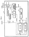
このような処理を行なうために、空燃比処理制御器15は、図4に示すような機能的構成を具備している。
【0158】
すなわち、空燃比処理制御器15は、前記O2センサ12の出力VO2/OUTから前記目標値VO2/TARGETを減算することで前記偏差出力VO2を逐次求める減算処理器22と、前記対象等価系18のモデル(式(1))の設定すべきパラメータである前記ゲイン係数a1,a2,b1の同定値a1ハット,a2ハット,b1ハット(以下、同定ゲイン係数a1ハット,a2ハット,b1ハットという)を逐次求める同定器23(同定手段)とを具備する。
【0159】
また、空燃比処理制御器15は、前記対象等価系18の無駄時間d後のO2センサ12の出力の推定値を表すデータとして、該無駄時間d後のO2センサ12の偏差出力VO2の推定値VO2バー(以下、推定偏差出力VO2バーという)を逐次求める推定器24(推定手段)と、フィードバック制御の一手法である適応スライディングモード制御のアルゴリズムにより、O2センサ12の出力VO2/OUTを目標値VO2/TARGETに収束させるために要求される前記目標合成偏差空燃比kcmd/tを逐次求めるスライディングモード制御器25(目標合成空燃比データ生成手段)とを具備する。
【0160】
また、空燃比処理制御器15は、スライディングモード制御器25が求めた目標合成偏差空燃比kcmd/tに対して前記式(5)の演算処理(変換処理)を行なうことで、各気筒群3,4に対する目標偏差空燃比kcmdを逐次求める目標偏差空燃比算出器26(目標空燃比データ生成手段)と、その目標偏差空燃比kcmdに前記基準空燃比FLAF/BASEを加算することで各気筒群3,4に対する目標空燃比KCMDを逐次求める加算処理器27とを具備する。
【0161】
さらに、本実施形態では、燃料供給制御器16は、後述するように、エンジン1の運転状態等によっては、空燃比処理制御器15が求めた目標空燃比KCMDを使用せずに、それとは別に定めた目標空燃比を使用して各気筒群3,4で実際に燃焼させる混合気の空燃比を操作することがある(以下、この別の目標空燃比を含めて燃料供給制御器16が各気筒群3,4の空燃比を操作するために実際に使用する目標空燃比を実使用目標空燃比RKCMDという)。そして、詳細は後述するが、この実使用目標空燃比RKCMDを前記同定器23や推定器24の演算処理に反映させるために、次のような機能的構成も具備している。
【0162】
すなわち、空燃比処理制御器15は、燃料供給制御器16から与えられる実使用目標空燃比RKCMDから前記基準空燃比FLAF/BASEを減算することで、燃料供給制御器16が実際に使用している目標偏差空燃比に相当する実使用目標偏差空燃比rkcmd(=RKCMD−FLAF/BASE)を逐次求める減算処理器28と、この実使用目標偏差空燃比rkcmdに対して、前記式(4)の右辺と同じ形のフィルタリング処理を施すことで、燃料供給制御器16が実際に使用している実使用目標偏差空燃比rkcmdの基礎となる目標合成偏差空燃比としての実使用目標合成偏差空燃比rkcmd/t(実使用目標合成空燃比データ)を逐次生成するフィルタ29(フィルタ手段)とを具備する。
【0163】
この場合、このフィルタ29のフィルタリング処理は、具体的には、次式(7)により与えられ、この式(7)により、空燃比処理制御器15の制御サイクル毎に、前記実使用目標合成偏差空燃比rkcmd/t(k)が求められる。
【0164】
【数7】
つまり、制御サイクル毎の実使用目標合成偏差空燃比rkcmd/t( k)は、その制御サイクル以前に、燃料供給制御器16が使用しており、あるいは使用した実使用目標空燃比RKCMDに相当する実使用目標偏差空燃比rkcmdの時系列データrkcmd(k),rkcmd(k-1),rkcmd(k-dD),rkcmd(k-dD-1)から式(7)のフィルタリング処理によって算出される。
【0166】
尚、空燃比処理制御器15の各制御サイクルにおいて燃料供給制御器16が実際に使用している実使用目標空燃比RKCMD(k)は、通常的には、前回の制御サイクルで空燃比処理制御器15が最終的に求めた目標空燃比KC MD(k-1)に等しい。つまり、通常的には、rkcmd(k)=kcmd(k-1)である。従って、前記フィルタ29が制御サイクル毎に求める実使用目標合成偏差空燃比rkcmd/t(k)は、スライディングモード制御器25が後述する如く求める目標合成偏差空燃比kcmd/tの前回値kcmd/t(k-1)に対応するものである(通常的には、rkcmd/t(k)=kcmd/t(k-1))。
【0167】
前記同定器23、推定器24及びスライディングモード制御器25による処理のアルゴリズムは以下のように構築されている。
【0168】
まず、同定器23は、前記対象等価系18のモデルのモデル化誤差を極力小さくするように前記同定ゲイン係数a1ハット,a2ハット,b1ハットをリアルタイムで逐次更新しつつ算出するものであり、その同定処理を次のように行う。
【0169】
すなわち、同定器23は、空燃比処理制御器15の制御サイクル毎に、まず、対象等価系18のモデルを表す前記式(1)を1制御サイクル分、過去側にシフトし、ゲイン係数a1,a2,b1を前回の制御サイクルで決定した同定ゲイン係数a1(k-1)ハット,a2(k-1)ハット,b1(k-1)ハット(同定ゲイン係数の現在値)で置き換えてなる次式(8)を基礎として、対象等価系18のモデル上での現在の制御サイクルにおけるO2センサ12の偏差出力VO2(k)(以下、同定偏差出力VO2(k)ハットという)の値を求める。
【0170】
【数8】
ここで、この式(8)によれば、制御サイクル毎の上記同定偏差出力VO2(k)ハットは、基本的には、前回の制御サイクルで決定した同定ゲイン係数a1(k-1)ハット,a2(k-1)ハット,b1(k-1)ハットと、O2センサ12の偏差出力VO2の過去値VO2(k-1),VO2(k-2)と、目標合成偏差空燃比kcmd /t(これは後述するスライディングモード制御器25により求められる)の過去値kcmd/t(k-d-1)とを用いて式(10)の右辺の演算を行うことで、求めることができる。
【0172】
しかるに、本実施形態では、先にも述べたように、燃料供給制御器16は、空燃比処理制御器15が生成する目標空燃比KCMDを使用せずに、各気筒群3,4における空燃比を操作する場合がある。このため、対象等価系18の基礎となる前記対象系17の実際の挙動状態を逐次反映させながら、前記ゲイン係数a1,a2,b1の値を同定する上では、空燃比処理制御器15が生成する目標空燃比KCMDに対応して定まる目標合成偏差空燃比kcmd/tを用いるよりも、前記フィルタ29により逐次求められる実使用目標合成偏差空燃比rkcmd/tを用いることが好ましいと考えられる。
【0173】
そこで、本実施形態では、前記式(8)の右辺の目標合成偏差空燃比kcmd/tの代わりに、フィルタ29が求める実使用目標合成偏差空燃比rkcmd/tを用いて、制御サイクル毎の上記同定偏差出力VO2(k)ハットを求めることとする。
【0174】
この場合、前述のように、通常的には、rkcmd/t(k)=kcmd/t(k-1)であることを考慮すると、同定偏差出力VO2(k)ハットは、具体的には、次式(9)により求められる。
【0175】
【数9】
つまり、本実施形態では、同定器23は、まず、前回の制御サイクルで決定した同定ゲイン係数a1(k-1)ハット,a2(k-1)ハット,b1(k-1)ハットの値と、前記減算処理器22が算出したO2センサ12の偏差出力VO2の過去値のデータ(詳しくは1制御サイクル前の偏差出力VO2(k-1)と2制御サイクル前の偏差出力VO2(k-2))と、前記フィルタ29が算出した実使用目標合成偏差空燃比rkcmd/tの過去値のデータ(詳しくは対象等価系18の無駄時間d前の制御サイクルにおける実使用目標合成偏差空燃比rkcmd/t(k-d))とを用いて、式(9)の演算を行うことで、制御サイクル毎の同定偏差出力VO2(k)ハットの値を求める。
【0177】
尚、式(9)の第3項で用いる対象等価系18の無駄時間dの値は、前述の如く設定した値(一定値。これは本実施形態では、前記気筒群4側無駄時間dBの設定値である)を用いる。また、式(9)中の「Θ」,「ξ」は、同式(9)の但し書きで定義したベクトルである。そして、式(9)やその但し書き中で用いている「T」は転置を意味する(以下、同様)。
【0178】
さらに同定器23は、上記同定偏差出力VO2(k)ハットと今現在のO2センサ12の実際の偏差出力VO2(k)との偏差ID/E(k)を、対象等価系18のモデルのモデル化誤差を表すものとして次式(10)により求める(以下、この偏差ID/Eを同定誤差ID/Eという)。
【0179】
【数10】
同定器23は、上記同定誤差ID/E(より正確には同定誤差ID/Eの絶対値)を最小化するようなアルゴリズムにより、新たな同定ゲイン係数a1(k)ハット,a2(k)ハット,b1(k)ハット、換言すれば、これらの同定ゲイン係数を成分とする新たな前記ベクトルΘ(k)(以下、このベクトルを同定ゲイン係数ベクトルΘという)を求めるものであり、その算出を、次式(11)により行う。
【0181】
【数11】
すなわち、同定器23は、前回の制御サイクルで決定した同定ゲイン係数a1(k-1)ハット,a2(k-1)ハット,b1(k-1)ハットを、同定誤差ID/E(k)に比例させた量だけ変化させることで新たな同定ゲイン係数ar1(k)ハット,ar2(k)ハット,br1(k)ハットを求める。
【0183】
ここで、式(11)中の「Kp(k)」は制御サイクル毎に次式(12)により決定される三次のベクトルで、各同定ゲイン係数a1ハット,a2ハット,b1ハットの同定誤差ID/Eに応じた変化度合い(ゲイン)を規定するものである。
【0184】
【数12】
また、上式(12)中の「P(k)」は制御サイクル毎に次式(13)の漸化式により更新される三次の正方行列である。
【0186】
【数13】
尚、式(13)中の行列P(k)の初期値P(0)は、その各対角成分を正の数とした対角行列である。また、式(13)中の「λ1」、「λ2」は0<λ1≦1及び0≦λ2<2の条件を満たすように設定される。
【0188】
この場合、上記λ1,λ2の設定の仕方によって、最小2乗法、重み付き最小2乗法、固定ゲイン法、漸減ゲイン法、固定トレース法等、各種の具体的なアルゴリズムが構成される。本実施形態では、例えば最小2乗法(この場合、λ1=λ2=1)を採用している。
【0189】
本実施形態における同定器23は基本的には前述のようなアルゴリズム(詳しくは逐次型最小二乗法の演算処理)によって、前記同定誤差ID/Eを最小化するように前記同定ゲイン係数a1ハット,a2ハット,b1ハットを制御サイクル毎に逐次更新しつつ求める。このような処理によって、実際の対象等価系18の挙動に適合した同定ゲイン係数a1ハット,a2ハット,b1ハットがリアルタイムで逐次求められる。
【0190】
以上説明したアルゴリズムが同定器23による基本的な処理のアルゴリズムである。
【0191】
次に、前記推定器24は、後に詳細を説明するスライディングモード制御器25による目標合成偏差空燃比kcmd/tの算出処理に際しての対象等価系18の無駄時間d(本実施形態ではd=7)の影響を補償するために、その無駄時間d後のO2センサ12の偏差出力VO2の推定値である前記推定偏差出力VO2バーを制御サイクル毎に逐次求めるものである。
【0192】
このようなO2センサ12の推定偏差出力VO2バーを求めるアルゴリズムは前記式(1)により表現した対象等価系18のモデルに基づいて次のように構築されている。
【0193】
すなわち、式(1)を用いることで、各制御サイクルにおける前記無駄時間d後のO2センサ12の偏差出力VO2(k+d)の推定値である推定偏差出力VO2(k+d)バーは、O2センサ12の偏差出力VO2の時系列データVO2(k),VO2(k-1)と、前記目標合成偏差空燃比kcmd/tの過去値の時系列データkcmd/t(k-j)(j=1,2,…,d)とを用いて次式(14)により表される。
【0194】
【数14】
ここで、式(14)において、「α1」,「α2」は、それぞれ同式(14)の但し書きで定義した行列Aのべき乗Ad(d:無駄時間)の第1行第1列成分、第1行第2列成分である。また、「βj」(j=1,2,…,d)は、それぞれ、行列Aのべき乗Aj-1(j=1,2,…,d)と同式(14)の但し書きで定義したベクトルBとの積Aj-1・Bの第1行成分である。
【0196】
さらに、この式(17)において、の目標合成偏差空燃比kcmd/tの過去値の時系列データkc md/t(k-1),…,kcmd/t(k-d2+1)は、基本的には、燃料供給制御器16がエンジン1の各気筒群3,4の空燃比を操作するために現在使用しており、あるいは過去に使用した実使用目標空燃比RKCMDに対応するものであるが、先に述べたように該燃料供給制御器16は空燃比処理制御器15が求める目標空燃比KCMD以外の別の目標空燃比を各気筒群3,4の操作のために使用することがある。従って、前記同定器23の場合と同様に、対象等価系18の基礎となる前記対象系17の実際の挙動状態を逐次反映させながら、前記推定偏差出力VO2(k+d)バーを求めるためには、空燃比処理制御器15が生成する目標空燃比KCMDに対応して定まる目標合成偏差空燃比kcmd/tを用いるよりも、前記フィルタ29により逐次求められる実使用目標合成偏差空燃比rkcmd/tを用いることが好ましいと考えられる。
【0197】
そこで、本実施形態では、通常的には、rkcmd/t(k)=kcmd/t(k-1)であることも考慮し、式(14)の目標合成偏差空燃比kcmd/tの過去値の時系列データkcmd/t(k-j)(j=1,2,…,d)の代わりに、前記フィルタ29が逐次求める前記実使用目標合成偏差空燃比rkcmd/tの現在値及び過去値の時系列データrkcmd/t(k-j+1)(j=1,2,…,d)を用いることとする。そして、次式(15)により、制御サイクル毎の推定偏差出力VO2(k+d)バーを求めることとする。
【0198】
【数15】
つまり、本実施形態では、推定器24は、制御サイクル毎に、O2センサ12の偏差出力VO2の現在値及び過去値の時系列データVO2(k),VO2(k-1)と、前記フィルタ29が求める前記実使用目標合成偏差空燃比rkcmdの現在値及び過去値の時系列データrkcmd (k-j+1)(j=1,…,d)とを用いて式(15)の演算を行うことによって、O2センサ12の推定偏差出力VO2(k+d)バーを求める。
【0200】
この場合、式(15)の演算に必要な係数値α1,α2及びβ(j)(j=1,2,…,d)は、基本的には、前記同定器23によって求められた同定ゲイン係数a1ハット,a2ハット,b1ハットの最新値(現在の制御サイクルで求めた値)から、式(14)の但し書きの定義に従って算出する。また、式(15)の演算に必要な対象等価系18の無駄時間dは前述の如く設定した値を用いる。
【0201】
以上説明した処理が、推定器24が実行する基本的アルゴリズムである。
【0202】
次に、前記スライディングモード制御器25を説明する。
【0203】
スライディングモード制御器25は、通常的なスライディングモード制御に外乱等の影響を極力排除するための適応則(適応アルゴリズム)を加味した適応スライディングモード制御のアルゴリズムによって、O2センサ12の出力VO2/OUTをその目標値VO2/TARGETに収束させる(O2センサ12の偏差出力VO2を「0」に収束させる)ために要求される目標合成偏差空燃比kcmd/t(対象等価系18に与えるべき制御入力)を制御サイクル毎に逐次求めるものである。そして、その処理のためのアルゴリズムは以下に説明するように構築されている。
【0204】
まず、スライディングモード制御器25が実行する適応スライディングモード制御のアルゴリズムに必要な切換関数と、この切換関数により定義される超平面(これはすべり面とも言われる)とについて説明する。
【0205】
スライディングモード制御器25によるスライディングモード制御の基本的な考え方としては、制御すべき状態量(制御量)を、例えばO2センサ12の偏差出力VO2の複数の時系列データとし、スライディングモード制御用の切換関数σを次式(16)により定義する。
【0206】
【数16】
すなわち、該切換関数σは、O2センサ12の偏差出力VO2の現在以前の複数(本実施形態では二つ)の時系列データVO2(k),VO2(k-1)(詳しくは、現在の制御サイクルと前回の制御サイクルとにおける偏差出力VO2(k),VO2(k-1))を成分とする線形関数(時系列データVO2(k),VO2(k-1)の線形結合)により定義する。尚、偏差出力VO2(k),VO2(k-1)を成分とするベクトルとして式(16)中で定義したベクトルXを以下、状態量Xという。
【0208】
この場合、切換関数σの成分VO2(k),VO2(k-1)に係る係数s1,s2は、次式(17)の条件を満たすような値にあらかじめ設定しておく。この条件は、切換関数σの値が「0」となる状態で、偏差出力VO2が安定に「0」に収束するために係数s1,s2が満たすべき条件である。
【0209】
【数17】
尚、本実施形態では、簡略化のために係数s1をs1=1とし(この場合、s2/s1=s2である)、−1<s2<1の条件を満たすように係数s2の値(一定値)を設定している。
【0211】
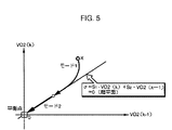
このような切換関数σに対して、スライディングモード制御用の超平面はσ=0なる式によって定義されるものである。この場合、前記状態量Xは二次系であるので超平面σ=0は図5に示すように直線となり、このとき、該超平面σ=0は切換線とも言われる。
【0212】
尚、本実施形態では、切換関数の成分として、実際には前記推定器24により求められる前記推定偏差出力VO2バーの時系列データを用いるのであるが、これについては後述する。
【0213】
スライディングモード制御器25が用いる適応スライディングモード制御は、状態量X=(VO2(k),VO2(k-1))を上記の如く設定した超平面σ=0に収束させる(切換関数σの値を「0」に収束させる)ための制御則である到達則と、その超平面σ=0への収束に際して外乱等の影響を補償するための制御則である適応則(適応アルゴリズム)とにより該状態量Xを超平面σ=0に収束させる(図5のモード1)。そして、該状態量Xを所謂、等価制御入力によって超平面σ=0に拘束しつつ(切換関数σの値を「0」に保持する)、該状態量Xを超平面σ=0上の平衡点であるVO2(k)=VO2(k-1)=0となる点、すなわち、O2センサ12の出力VO2/OUTの時系列データVO2/OUT(k ),VO2/OUT(k-1)が目標値VO2/TARGETに一致するような点に収束させる(図5のモード2)。
【0214】
尚、通常的なスライディングモード制御では、前記モード1において適応則が省略され、到達則のみによって、状態量Xを超平面σ=0に収束させる。
【0215】
上記のように状態量Xを超平面σ=0の平衡点に収束させるためにスライディングモード制御器25が生成する目標合成偏差空燃比kcmd/tは、状態量Xを超平面σ=0上に拘束するための制御則に従って前記対象等価系18に与えるべき入力成分である等価制御入力ueqと、前記到達則に従って対象等価系18に与えるべき入力成分urch(以下、到達則入力urchという)と、前記適応則に従って対象等価系18に与えるべき入力成分uadp(以下、適応則入力uadpという)との総和により与えられる(次式(18))。
【0216】
【数18】
これらの等価制御入力ueq、到達則入力urch及び適応則入力uadpは、本実施形態では、前記式(1)により表した対象等価系18のモデルに基づいて次のように決定する。
【0218】
まず、前記状態量Xを超平面σ=0に拘束する(切換関数σの値を「0」に保持する)ために対象等価系18に与えるべき入力成分である前記等価制御入力ueqは、σ(k+1)=σ(k)=0なる条件を満たす目標合成偏差空燃比kcmd/tである。そして、このような条件を満たす等価制御入力ueqは、式(1)と式(16)とを用いて次式(19)により与えられる。
【0219】
【数19】
この式(19)が、各制御サイクルにおける等価制御入力ueq(k)を求めるための基本式である。
【0221】
また、前記到達則入力urchは、本実施形態では、基本的には次式(20)により決定するものとする。
【0222】
【数20】
すなわち、各制御サイクルにおける到達則入力ur ch(k)は、対象等価系18の無駄時間dを考慮し、その無駄時間d後の切換関数σ(k+d)の値に比例させるように決定する。
【0224】
この場合、式(20)中の係数F(これは到達則のゲインを規定する)は、次式(21)の条件を満たすように設定する。
【0225】
【数21】
尚、式(21)に示した係数Fの好ましい条件は、切換関数σの値が「0」に対して振動的な変化(所謂チャタリング)を生じるのを抑制する上で好適な条件である。
【0227】
また、前記適応則入力uadpは、本実施形態では、基本的には次式(22)により決定するものとする。ここで式(22)中のΔTは空燃比処理制御器15の制御サイクルの周期(一定値)である。
【0228】
【数22】
すなわち、各制御サイクルにおける適応則入力uadp(k)は、対象等価系18の無駄時間dを考慮し、該無駄時間d後までにおける切換関数σの値と制御サイクルの周期ΔTとの積の制御サイクル毎の積算値(これは切換関数σの値の積分値に相当する)に比例させるように決定する。
【0230】
この場合、式(22)中の係数G(これは適応則のゲインを規定する)は、次式(23)の条件を満たすように設定する。
【0231】
【数23】
尚、前記式(21)、(23)の設定条件のより具体的な導出の仕方については、本願出願人が既に特開平11−93741号公報等にて詳細に説明しているので、ここでは詳細な説明を省略する。
【0233】
前記対象等価系18に与えるべき制御入力としてスライディングモード制御器25が生成する目標合成偏差空燃比kcmd/tは、基本的には前記式(19)、(20)、(22)により決定される等価制御入力ueq、到達則入力urch及び適応則入力uadpの総和(ueq+urch+uadp)として決定すればよい。しかるに、前記式(19)、(20)、(22)で使用するO2センサ12の偏差出力VO2(k+d),VO2(k+d-1)や、切換関数σの値σ(k+d)等は未来値であるので直接的には得られない。
【0234】
そこで、スライディングモード制御器25は、前記式(19)の演算に必要な偏差出力VO2(k+d),VO2(k+d-1)の代わりに、それらの推定値(予測値)として前記推定器24が前述の如く求める推定偏差出力VO2(k+d)バー,VO2(k+d-1)バーを用い、次式(24)により制御サイクル毎の等価制御入力ueq(k)を算出する。
【0235】
【数24】
また、本実施形態では、実際には、推定器24により前述の如く逐次求められた推定偏差出力VO2バーの時系列データを制御すべき状態量とし、前記式(16)により定義した切換関数σに代えて、次式(25)により切換関数σバーを定義する(この切換関数σバーは、前記式(16)の偏差出力VO2の時系列データを推定偏差出力VO2バーの時系列データで置き換えたものである)。
【0237】
【数25】
そして、スライディングモード制御器25は、前記式(20)により前記到達則入力urchを決定するための切換関数σの値の代わりに、前記式(25)により表される切換関数σバーの値を用いて次式(26)により制御サイクル毎の到達則入力urch(k)を算出する。
【0239】
【数26】
同様に、スライディングモード制御器25は、前記式(22)により前記適応則入力uadpを決定するための切換関数σの値の代わりに、前記式(20)により表される切換関数σバーの値を用いて次式(27)により制御サイクル毎の適応則入力uadp(k)を算出する。
【0241】
【数27】
尚、前記式(24),(26),(27)により等価制御入力ueq、到達則入力urch及び適応則入力uadpを算出する際に必要となる前記ゲイン係数a1,a2,b1は、基本的には前記同定器23により求められた最新の同定ゲイン係数a1(k)ハット,a2(k)ハット,b1(k)ハットを用いる。
【0243】
そして、スライディングモード制御器25は、前記式(24),(26),(27)によりそれぞれ求められる等価制御入力ueq、到達則入力urch及び適応則入力uadpの総和を目標合成偏差空燃比kcmd/tとして求める(前記式(18)を参照)。尚、この場合において、前記式(24),(26),(27)中で用いる前記係数s1,s2,F,Gの設定条件は前述の通りである。
【0244】
このようにしてスライディングモード制御器25が求める目標合成偏差空燃比kcmd/tは、O2センサ12の推定偏差出力VO2バーを「0」に収束させ、その結果としてO2センサ12の出力VO2/OUTを目標値VO2/TARGETに収束させる上で、対象等価系18に与えるべき制御入力である。
【0245】
以上説明した処理が、スライディングモード制御器25により目標合成偏差空燃比kcmd/tを制御サイクル毎に生成するための基本的なアルゴリズムである。
【0246】
次に、前記燃料供給制御器16を説明する。
【0247】
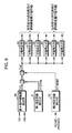
燃料供給制御器16は、図6に示すように、その機能的構成として、エンジン1の基本燃料噴射量Timを求める基本燃料噴射量算出部30と、基本燃料噴射量Timを補正するための第1補正係数KTOTAL及び第2補正係数KCMDMをそれぞれ求める第1補正係数算出部31及び第2補正係数算出部32と、これらの第1補正係数KTOTAL及び第2補正係数KCMDMにより基本燃料噴射量Timを補正してなる出力燃料噴射量Toutに、エンジン1の各気筒群3,4の各気筒毎に、図示しない吸気管の壁面への燃料の付着を考慮した補正を施す複数(エンジン1の気筒数と同数)の付着補正部33とを具備する。
【0248】
前記基本燃料噴射量算出部30は、エンジン1の回転数NEと吸気圧PBとから、それらに応じたエンジン1の基準の燃料噴射量(燃料供給量)をあらかじめ設定されたマップを用いて求め、その基準の燃料噴射量をエンジン1の図示しないスロットル弁の有効開口面積に応じて補正することで基本燃料噴射量Timを算出するものである。この基本燃料噴射量Timは、基本的には、エンジン1のクランク角周期の1周期(1TDC)当たりにエンジン1の各気筒に吸入される空気量と基本燃料噴射量Timとの比、すなわち空燃比が理論空燃比となるような燃料噴射量である。尚、この基本燃料噴射量Timはエンジン1の両気筒群3,4について共通である。
【0249】
また、第1補正係数算出部31が求める第1補正係数KTOTALは、エンジン1の排気還流率(エンジン1の吸入空気中に含まれる排ガスの割合)や、エンジン1の図示しないキャニスタのパージ時にエンジン1に供給される燃料のパージ量、エンジン1の冷却水温、吸気温等を考慮して前記基本燃料噴射量Timを補正するためのものである。
【0250】
また、第2補正係数算出部32が求める第2補正係数KCMDMは、エンジン1の各気筒群3,4で燃焼させる混合気の空燃比を前記空燃比処理制御器15が生成した目標空燃比KCMDに操作するために基本燃料噴射量Timをフィードフォワード的に補正するものであり、目標空燃比KCMDから、あらかじめ定められたデータテーブル(図示しない)を用いて求められる。このデータテーブルにより求められる第2補正係数KCMDMは、目標空燃比KCMDが理論空燃比に一致するとき「1」で、目標空燃比KCMDが理論空燃比よりも燃料のリッチ寄りの値になる程、「1」よりも大きな値とされる。また、目標空燃比KCMDが理論空燃比よりも燃料のリーン寄りの値になる程、第2補正係数KCMDMは「1」よりも小さな値とされる。より詳しくは、第2補正係数KCMDMは、目標空燃比KCMDの理論空燃比に対する比(目標空燃比KCMD/理論空燃比)の逆数値に、エンジン1の燃料噴射時の冷却効果による吸入空気量の充填効率を考慮した補正を施してなるものである。
【0251】
尚、これらの基本燃料噴射量Tim、第1補正係数KTOTAL、第2補正係数KCMDMは、エンジン1の両気筒群3,4について共通である。
【0252】
燃料供給制御器16は、上記のように求められる第1補正係数KTOTAL及び第2補正係数KCMDMを、基本燃料噴射量Timに乗算することで、該基本燃料噴射量Timを補正し、その補正してなる値を出力燃料噴射量Timとして得る。そして、この出力燃料噴射量Timに、前記付着補正部33によって、エンジン1の各気筒毎の図示しない吸気管の壁面への燃料の付着を考慮した補正を施したものを、各気筒群3,4の各気筒に対する燃料噴射量の最終的な指令値として決定し、それを図示しない燃料噴射装置に指令する。
【0253】
尚、前記基本燃料噴射量Timや、第1補正係数KTOTAL、第2補正係数KCMDMのより具体的な算出手法は、特開平5−79374号公報等に本願出願人が開示しているので、ここでは詳細な説明を省略する。また、前記付着補正部33が行なう付着補正については、本願出願人が例えば特開平8−21273号公報に詳細に開示してるので、ここでは詳細な説明を省略する。
【0254】
また、上述した燃料供給制御器16の説明では、便宜上、各気筒群3,4における空燃比を制御するために常に空燃比処理制御器15が生成する目標空燃比KCMDを使用するものとした。具体的には、前記第2補正係数算出部32が、その処理を行なうために、空燃比処理制御器15が生成する目標空燃比KCMDを使用するものとした。但し、燃料供給制御器16は、各気筒群3,4における空燃比を操作するために、後述するエンジン1の特定の運転状況下等(具体的には、エンジン1のフュエルカット中や、スロットル弁の全開時等)では、空燃比処理制御器15が逐次生成する目標空燃比KCMDとは別に定めた目標空燃比を上記第2補正係数算出部32で使用する場合がある。そして、この場合には、前述した制御処理に用いる目標空燃比KCMDの値を強制的に当該別の目標空燃比の値に設定して、各気筒群3,4における空燃比を制御する。つまり、前記第2補正係数算出部32がその処理で使用する目標空燃比KCMDは、実際には、前記した実使用目標空燃比RKCMD(通常的には、RKCMD=KCMD)である。
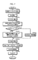
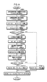
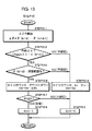
図面の説明図面の説明 次に、本実施形態のシステムの全体の作動を詳細に説明する。
【0255】
まず、図7及び図8のフローチャートを参照して、燃料供給制御器16による制御処理について説明する。燃料供給制御器16は、この処理をエンジン1のクランク角周期(TDC)と同期した制御サイクルで次のように行う。
【0256】
燃料供給制御器16は、まず、エンジン1の回転数NE、吸気圧PB等を検出する図示しないセンサやO2センサ12等、各種センサの出力を読み込む(STEPa)。
【0257】
この場合、本実施形態では、前記空燃比処理制御器15の処理に必要なO2センサ12の出力VO2/OUTは燃料供給制御器16を介して空燃比処理制御器15に与えられるようになっている。このため、O2センサ12の出力VO2/OUTの読み込まれたデータは、過去の制御サイクルで取得したものを含めて図示しないメモリに時系列的に記憶保持される。
【0258】
次いで、基本燃料噴射量算出部30によって、前述の如くエンジン1の回転数NE及び吸気圧PBに対応する燃料噴射量をスロットル弁の有効開口面積に応じて補正してなる基本燃料噴射量Timが求められる(STEPb)。さらに、第1補正係数算出部31によって、エンジン1の冷却水温やキャニスタのパージ量等に応じた第1補正係数KTOTALが算出される(STEPc)。
【0259】
次いで、燃料供給制御器16は、前記空燃比処理制御器15が求める目標空燃比KCMDをエンジン1の各気筒群3,4における空燃比を実際に操作するために使用するか否か(ここでは、空燃比操作のON/OFFという)の判別処理を行って、この空燃比操作のON/OFFを規定するフラグf/prism/onの値を設定する(STEPd)。このフラグf/prism/onの値は、それが「0」のとき、空燃比処理制御器15が求める目標空燃比KCMDを使用しないこと(OFF)を意味し、「1」のとき、空燃比処理制御器15が生成する目標空燃比KCMDを使用すること(ON)を意味する。
【0260】
上記の判別処理では、図8に示すように、まず、O2センサ12が活性化しているか否かの判別が行われる(STEPd−1)。この判別は、例えばO2センサ12の出力電圧に基づいて行われる。
【0261】
このとき、O2センサ12が活性化していない場合には、空燃比処理制御器15の処理に使用するO2センサ12の出力データ(検出データ)を精度よく得ることができないため、フラグf/prism/onの値を「0」にセットする(STEPd−9)。
【0262】
また、エンジン1のリーン運転中(希薄燃焼運転)であるか否か、エンジン1の始動直後の触媒装置3,4の早期活性化を図るためにエンジン1の点火時期が遅角側に制御されているか否か、エンジン1のスロットル弁が全開であるか否か、及びエンジン1のフュエルカット中(燃料供給の停止中)であるか否かの判別が行われる(STEPd−2〜d−5)。そして、これらのいずれかの条件が成立している場合には、空燃比処理制御器15が生成する目標空燃比KCMDを使用してエンジン1の空燃比を操作することは好ましくないか、もしくは操作することができないので、フラグf/prism/onの値を「0」にセットする(STEPd−9)。
【0263】
さらに、エンジン1の回転数NE及び吸気圧PBがそれぞれ所定範囲内(正常な範囲内)にあるか否かの判別が行われ(STEPd−6,d−7)、いずれかが所定範囲内にない場合には、空燃比処理制御器15が生成する目標空燃比KCMDを使用してエンジン1の空燃比を操作することは好ましくないので、フラグf/prism/onの値を「0」にセットする(STEPd−9)。
【0264】
そして、STEPd−1,d−6,d−7の条件が満たされ、且つ、STEPd−2〜d−5の条件が成立していない場合に(このような場合はエンジン1の通常的な運転状態である)、空燃比処理制御器15が生成する目標空燃比KCMDをエンジン1の空燃比の操作に使用すべく、フラグf/prism/onの値を「1」にセットする(STEPd−8)。
【0265】
図7に戻って、上記のようにフラグf/prism/onの値を設定した後、燃料供給制御器16は、フラグf/prism/onの値を判断する。(STEPe)。そして、このとき、f/prism/on=1である場合には、空燃比処理制御器15が生成した最新の目標空燃比KCMDを今回の制御サイクルにおける実使用目標空燃比RKCMDとして読み込む(STEPf)。また、f/prism/on=0である場合には、例えばエンジン1の回転数NEや吸気圧PBからあらかじめ定めたマップ等を用いて求めた所定値を今回の制御サイクルにおける実使用目標空燃比RKCMDとして設定する(STEPg)。
【0266】
尚、上記STEPe〜gの処理で燃料供給制御器16が決定した実使用目標空燃比RKCMDの値は、該燃料供給制御器16において、図示しないメモリに時系列的に記憶保持される。
【0267】
さらに、燃料供給制御器16は、上記STEPf又はSTEPgで決定された実使用目標空燃比RKCMDに応じた前記第2補正係数KCMDMを第2補正係数算出部32により算出する(STEPh)。
【0268】
次いで、燃料供給制御器16は、前述のように求められた基本燃料噴射量Timに、第1補正係数KTOTAL及び第2補正係数KCMDMを乗算することで、各気筒群3,4に対する出力燃料噴射量Toutを求める(STEPi)。そして、この出力燃料噴射量Toutが、付着補正部33によって、各気筒群3,4の各気筒毎に、吸気管の壁面への燃料の付着を考慮した補正が施された後(STEPj)、最終的な燃料噴射量の指令値として、エンジン1の図示しない燃料噴射装置に出力される(STEPk)。
【0269】
そして、エンジン1にあっては、各気筒群3,4の各気筒毎の出力燃料噴射量Toutに従って、各気筒への燃料噴射が行われる。
【0270】
以上のようなエンジン1の燃料噴射の制御がエンジン1のクランク角周期(TDC)に同期した制御サイクルで逐次行われ、これにより、各気筒群3,4で燃焼させる混合気の空燃比が前記実使用目標空燃比RKCMD(これは通常的には、空燃比処理制御器15が生成する目標空燃比KCMDである)にフィードフォワード的に操作される。すなわち、各気筒群3,4で燃焼する混合気の空燃比がフィードフォワード制御によって、前記実使用目標空燃比RKCMDに操作される。
【0271】
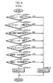
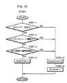
一方、前述のようなエンジン1の空燃比の操作(燃料噴射量の制御)と並行して、前記空燃比処理制御器15は、一定周期の制御サイクルで図9のフローチャートに示すメインルーチン処理を行う。
【0272】
すなわち、図9のフローチャートを参照して、空燃比処理制御器15は、まず、自身の演算処理(前記同定器23、推定器24、スライディングモード制御器25等の演算処理)を実行するか否かの判別処理を行なって、その実行の可否をそれぞれ値「1」、「0」で示すフラグf/prism/calの値を設定する(STEP1)。
【0273】
この判別処理は、図10のフローチャートに示すように行なわれる。
【0274】
すなわち、前記図7のSTEPdの場合と同様に、O2センサ12が活性化しているか否かの判別が行われる(STEP1−1)。このとき、O2センサ12が活性化していない場合には、空燃比処理制御器15の演算処理に使用するO2センサ12の検出データを精度よく得ることができないため、フラグf/prism/calの値を「0」にセットする(STEP1−5)。
【0275】
さらにこのとき、同定器23の後述する初期化を行うために、その初期化を行うか否かをそれぞれ値「1」、「0」で示すフラグf/id/resetの値を「1」にセットする(STEP1−6)。
【0276】
また、エンジン1のリーン運転中(希薄燃焼運転)であるか否か(STEP1−2)、及びエンジン1の始動直後の触媒装置9〜11の早期活性化を図るためにエンジン1の点火時期が遅角側に制御されているか否か(STEP1−3)の判別が行われる。これらのいずれかの条件が成立している場合には、O2センサ12の出力VO2/OUTを目標値VO2/TARGETに収束させるような目標空燃比KCMDを算出しても、それがエンジン1の燃料制御に使用されることはないので、フラグf/prism/calの値を「0」にセットする(STEP1−5)。さらにこのとき、同定器23の初期化を行うために、フラグf/id/resetの値を「1」にセットする(STEP1−6)。
【0277】
そして、STEP1−1の条件が満たされ、且つSTEP1−2,1−3の条件が成立していない場合には、フラグf/prism/calの値を「1」にセットする(STEP1−4)。
【0278】
尚、このようにフラグf/prism/calの値を設定することで、空燃比処理制御器15が生成する目標空燃比KCMDを燃料供給制御器16が使用しない状況(図8を参照)であっても、例えばエンジン1のフュエルカット中やスロットル弁の全開時には、フラグf/prism/calの値が「1」に設定される。従って、エンジン1のフュエルカット中や、スロットル弁の全開時には、空燃比処理制御器15は、同定器23、推定器24、スライディングモード制御器25等の演算処理(詳しくは、O2センサ12の出力VO2/OUTを目標値VO2/TARGETに収束させるための目標合成偏差空燃比kcmd/tを求める処理)を行なうこととなる。これは、このようなエンジン1の運転状況は基本的には一時的なものであるからである。
【0279】
図9に戻って、上記のような判別処理を行った後、空燃比処理制御器15は、さらに、同定器23による前記ゲイン係数a1,a2,b1の同定(更新)処理を実行するか否かの判別処理を行って、その実行の可否をそれぞれ値「1」、「0」で示すフラグf/id/calの値を設定する(STEP2)。
【0280】
このSTEP2の判別処理では、図示を省略するが、エンジン1のスロットル弁が全開であるか否か、及びエンジン1のフュエルカット中であるか否かの判別が行われる。これらのいずれかの条件が成立している場合には、前記ゲイン係数a1,a2,b1を適正に同定することができないため、フラグf/id/calの値を「0」にセットする。そして、上記のいずれの条件も成立していない場合には、同定器23による前記ゲイン係数a1,a2,b1の同定(更新)処理を実行すべくフラグf/id/calの値を「1」にセットする。
【0281】
次いで、空燃比処理制御器15は、前記減算処理器22によりO2センサ12の最新の偏差出力VO2(k)(=VO2/OUT−VO2/TARGET)を算出する(STEP3)。
【0282】
この場合、減算処理器22は、前記図7のSTEPaにおいて前記燃料供給制御器16が取り込んで図示しないメモリに記憶させたO2センサ12の出力VO2/OUTの時系列データの中から、最新のものを選択して前記偏差出力VO2(k)を算出する。
【0283】
さらに、このSTEP3では、前記減算処理器28により、燃料供給制御器16が各気筒群3,4の空燃比の制御のために現在使用している実使用目標空燃比RKCMDに相当する実使用目標偏差空燃比rkcmd(k)(=RKCMD−FLAF/BASE)を算出する。
【0284】
この場合、減算処理器28は、前述のように燃料供給制御器16がその制御サイクル毎に図示しないメモリに記憶保持する実使用目標空燃比RKCMDの時系列データの中から、最新のものを選択して実使用目標偏差空燃比rkcmdを算出する。ここで、燃料供給制御器16が現在使用している実使用目標空燃比RKCMDは、空燃比処理制御器15が前回の制御サイクルで求めた目標空燃比KCMD(k-1)に対応するもので、通常的には、該目標空燃比KCMD(k-1)に等しい。
【0285】
尚、上述のようにSTEP3で算出される偏差出力VO2及び実使用目標偏差空燃比rkcmdは、空燃比処理制御器15において、過去に算出したものを含めて時系列的に図示しないメモリに記憶保持される。
【0286】
次いで、空燃比処理制御器15は、前記フィルタ29によって、今回の制御サイクルにおける実使用目標合成偏差空燃比rkcmd/t(k)を算出する(STEP4)。
【0287】
この場合、前述のように記憶保持される実使用目標偏差空燃比rkcmdの時系列データの中から、現在値及び過去値の時系列データrkcmd(k),rkcmd(k-1),rkcmd(k-dD),rkcmd(k-dD-1)が選択され、それらのデータの値を用いて前記式(7)の右辺の演算を行うことで、実使用目標合成偏差空燃比rkcmd/t(k)が算出される。
【0288】
尚、上述のようにSTEP4で算出される実使用目標合成偏差空燃比rkcmdは、空燃比処理制御器15において、過去に算出したものを含めて時系列的に図示しないメモリに記憶保持される。
【0289】
次いで、空燃比処理制御器15は、前記STEP1で設定したフラグf/prism/calの値を判断する(STEP5)。このとき、f/prism/cal=0である場合、すなわち、空燃比処理制御器15の演算処理を行わない場合には、今回の制御サイクルにおける目標偏差空燃比kcmd(k)の値を強制的に所定値に設定する(STEP14)。この場合、該所定値は、例えばあらかじめ定めた固定値(例えば「0」)あるいは前回の制御サイクルで決定した目標偏差空燃比kcmdの値kcmd(k- 1)とする。
【0290】
尚、このように目標偏差空燃比kcmd(k)を所定値とした場合において、空燃比処理制御器15は、前記加算処理器27によって、その所定値の目標偏差空燃比kcmd(k)に前記基準空燃比FLAF/BASEを加算することで、今回の制御サイクルにおける目標空燃比KCMD(k)を決定し(STEP13)、今回の制御サイクルの処理を終了する。
【0291】
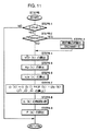
一方、STEP5の判断で、f/prism/cal=1である場合、すなわち、空燃比処理制御器15の演算処理を行う場合には、空燃比処理制御器15は、まず、前記同定器23による演算処理を行う(STEP6)。
【0292】
この同定器23による演算処理は図11のフローチャートに示すように行われる。
【0293】
すなわち、同定器23は、まず、前記STEP2で設定されたフラグf/id/calの値を判断する(STEP6−1)。このときf/id/cal=0であれば(エンジン1のスロットル弁が全開状態であるか、もしくはエンジン1のフュエルカット中の場合)、前述の通り同定器23によるゲイン係数a1,a2,b1の同定処理を行わないので、直ちに図9のメインルーチンに復帰する。
【0294】
一方、f/id/cal=1であれば、同定器23は、さらに該同定器23の初期化に係わる前記フラグf/id/resetの値(これは、前記STEP1でその値が設定される)を判断し(STEP6−2)、f/id/reset=1である場合には、同定器23の初期化を行う(STEP6−3)。この初期化では、前記同定ゲイン係数a1ハット,a2ハット,b1ハットの各値があらかじめ定めた初期値に設定される(前記同定ゲイン係数ベクトルΘが初期化される)。また前記式(13)の行列P(対角行列)の各成分があらかじめ定めた初期値に設定される。さらに、フラグf/id/res etの値は「0」にリセットされる。
【0295】
次いで、同定器23は、現在の同定ゲイン係数a1(k-1)ハット,a2(k-1)ハット,b1(k-1)ハット(前回の制御サイクルで求められた同定ゲイン係数)を用いて表される対象等価系18のモデル(前記式(8)参照)の出力である前記同定偏差出力VO2(k)ハットを前記式(9)によって算出する(STEP6−4)。すなわち、前記STEP3で制御サイクル毎に算出される偏差出力VO2の過去値のデータVO2(k-1),VO2(k-2)と、前記STEP4で制御サイクル毎に算出される実使用目標合成偏差空燃比rkcmd/tの過去値のデータrkcmd/t(k-d)と、上記同定ゲイン係数a1(k-1)ハット,a2(k-1)ハット,b1(k-1)ハットの値とを用いて前記式(9)により同定偏差出力VO2(k)ハットを算出する。
【0296】
さらに同定器23は、新たな同定ゲイン係数a1ハット,a2ハット,b1ハットを決定する際に使用する前記ベクトルKp(k)を式(12)により算出した後(STEP6−5)、前記同定誤差ID/E(k)(式(10)参照)を算出する(STEP6−6)。
【0297】
ここで、STEP6−6で求める同定誤差ID/E(k)は、基本的には、前記式(10)の演算により算出すればよいのであるが、本実施形態では、前記STEP3(図9参照)で制御サイクル毎に算出する偏差出力VO2と、前記STEP6−4で制御サイクル毎に算出する同定偏差出力VO2ハットとから式(10)の演算により得られた値(=VO2−VO2ハット)に、さらに所定の周波数通過特性(具体的にはローパス特性)を有するフィルタリング処理を施すことで同定誤差ID/E(k)を求める。
【0298】
このようなフィルタリング処理を行うのは次の理由による。すなわち、前記対象等価系18の入力量である目標合成空燃比KCMD/Tの変化に対する、該対象等価系18の出力量であるO2センサ12の出力VO2/OUTの変化の周波数特性は、特に対象等価系18の基礎となる前記対象排気系17に含まれる触媒装置9〜11の影響で、一般には低周波数側で高ゲインなものとなる。
【0299】
このため、対象等価系18のモデルのゲイン係数a1,a2,b1対象等価系18の実際の挙動特性に則して適正に同定する上では、該対象等価系18の低周波数側の挙動を重視することが好ましい。そこで、本実施形態では、式(10)の演算により得られた値(=VO2−VO2ハット)に、ローパス特性のフィルタリング処理を施すことで同定誤差ID/E(k)を求めるようにしている。
【0300】
尚、本実施形態で上記フィルタリングの周波数通過特性としたローパス特性は例示的なもので、より一般的には、実際の対象系17の挙動に基づいて、前記対象等価系18の入力量の変化に対する出力量の変化の周波数特性(これは触媒装置9〜11だけでなくエンジン1の特性が影響する場合もある)をあらかじめ実験等により確認しておき、その周波数特性が比較的高ゲインとなるような周波数域に通過特性を有するフィルタリングを行なうようにすればよい。
【0301】
また、上記のようなフィルタリング処理は、結果的に、偏差出力VO2及び同定偏差出力VO2ハットの両者に同じ周波数通過特性のフィルタリングが施されていればよく、例えば偏差出力VO2及び同定偏差出力VO2ハットにそれぞれ各別にフィルタリングを施した後に式(10)の演算を行って同定誤差ID/E(k)を求めるようにしてもよい。また、前記のフィルタリング処理は、例えばディジタルフィルタの一手法である移動平均処理によって行われる。
【0302】
上記のようにして同定誤差ID/E(k)を求めた後、同定器23は、この同定誤差ID/E(k)と、前記STEP5−5で算出したKp(k)とを用いて前記式(11)により新たな同定ゲイン係数ベクトルΘ(k)、すなわち、新たな同定ゲイン係数a1(k)ハット,a2(k)ハット,b1(k)ハットを算出する(STEP6−7)。
【0303】
このようにして新たな同定ゲイン係数a1(k)ハット,a2(k)ハット,b1(k)ハットを算出した後、同定器23は、同定ゲイン係数a1ハット,a2ハット,b1ハットの値を、所定の条件を満たすように制限する処理を行う(STEP6−8)。そして、同定器23は、次回の制御サイクルの処理のために前記行列P(k)を前記式(13)により更新し(STEP6−9)、図9のメインルーチンの処理に復帰する。
【0304】
この場合、上記STEP6−8における同定ゲイン係数a1ハット,a2ハット,b1ハットの値を制限する処理は、同定ゲイン係数a1ハット,a2ハットの値の組み合わせを所定の組み合わせに制限する処理(同定ゲイン係数a1ハット,a2ハットを成分とする座標平面上の所定の領域内に点(a1ハット,a2ハット)を制限する処理)と、同定ゲイン係数b1ハットの値を所定の範囲内に制限する処理とからなる。前者の処理では、STEP6−7で算出された同定ゲイン係数a1(k)ハット,a2(k)ハットにより定まる上記座標平面上の点(a1(k)ハット,a2(k)ハット)が該座標平面上にあらかじめ定めた所定の領域から逸脱している場合に同定ゲイン係数a1(k)ハット,a2(k)ハットの値を強制的に上記所定の領域内の点の値に制限する。また、後者の処理では、STEP6−7で算出された同定ゲイン係数b1ハットの値が所定の範囲の上限値あるいは下限値を超えている場合に、該同定ゲイン係数b1ハットの値を強制的にその上限値あるいは下限値に制限する。
【0305】
このような同定ゲイン係数a1ハット,a2ハット,b1ハットの制限処理は、スライディングモード制御器25が生成する目標合成偏差出力kcmd/tの安定性を確保するためのものである。
【0306】
尚、このような同定ゲイン係数a1ハット,a2ハット,b1ハットの制限処理のより具体的な手法については、本願出願人が例えば特願平10−106738号にて詳細に説明しているので、ここでは、詳細な説明を省略する。
【0307】
以上が図9のSTEP6における同定器23の演算処理の詳細である。
【0308】
図9のメインルーチン処理の説明に戻って、前述の通り同定器23の演算処理を行った後、空燃比処理制御器15はゲイン係数a1,a2,b1の値を決定する(STEP7)。
【0309】
この処理では、前記STEP2で設定されたフラグf/id/calの値が「1」である場合、すなわち、同定器23によるゲイン係数a1,a2,b1の同定処理を行った場合には、ゲイン係数a1,a2,b1の値として、それぞれ前記STEP6で前述の通り同定器23により求められた同定ゲイン係数a1(k)ハット,a2(k)ハット,b1(k)ハット(STEP6−8の制限処理を施したもの)を設定する。また、f/id/cal=0である場合、すなわち、同定器23によるゲイン係数a1,a2,b1の同定処理を行わなかった場合には、ゲイン係数a1,a2,b1の値をそれぞれ所定値に設定する。この場合、f/id/cal=0である場合(エンジン1のスロットル弁が全開状態であるか、もしくはエンジン1のフュエルカット中の場合)にゲイン係数a1,a2,b1の値として設定する所定値は、あらかじめ定めた固定値としてもよいが、f/id/cal=0となる状態が一時的であるような場合(同定器23による同定処理を一時的に中断する場合)には、f/id/cal=0となる直前に同定器23が求めた同定ゲイン係数a1ハット,a2ハット,b1ハットにゲイン係数a1,a2,b1の値を保持してもよい。
【0310】
次いで、空燃比処理制御器15は、図9のメインルーチンにおいて、前記推定器24による演算処理、すなわち現在の制御サイクルから対象等価系18の無駄時間d後のO2センサ12の偏差出力VO2の推定値である推定偏差出力VO2(k+d)バーを算出する処理を行う(STEP8)。
【0311】
このとき推定器24は、まず、前記STEP7で決定されたゲイン係数a1,a2,b1(これらの値は基本的には、前記図11のSTEP5−8の制限処理を経た同定ゲイン係数a1(k)ハット,a2(k)ハット,b1(k)ハットである)を用いて、前記式(15)で使用する係数値α1,α2,β(j)(j=1,2,…,d)をそれぞれ式(14)中の但し書きの定義に従って算出する。
【0312】
そして、推定器24は、前記図9のSTEP3で制御サイクル毎に算出されるO2センサ12の偏差出力VO2の現在の制御サイクル以前の二つの時系列データVO2(k),VO2(k-1)と、STEP4で制御サイクル毎に算出される前記実使用目標合成偏差空燃比rkcmd/tの現在値及び過去値の時系列データrkcmd/t(j)(j=1,…,d)と、上記の如く算出した係数値α1,α2,β(j)(j=1,2,…,d)とを用いて前記式(15)により、推定偏差出力VO2(k+d)バー(今回の制御サイクルの時点から無駄時間d後の偏差出力VO2の推定値)を算出する。
【0313】
尚、上記のように算出された推定偏差出力VO2(k+d)バーは、その値が過大あるいは過小なものになるのを防止するために、その値を所定の許容範囲内に制限するリミット処理が施され、その値が、該許容範囲の上限値あるいは下限値を超えている場合には、強制的に該上限値あるいは下限値に設定される。そして、これにより最終的に推定偏差出力VO2(k+d)バーの値が確定される。但し、通常的には、式(15)により算出される値がそのまま推定偏差出力VO2(k+d)バーとなる。
【0314】
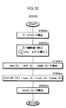
このように推定器24によりO2センサ12の推定偏差出力VO2(k+d)バーを求めた後、空燃比処理制御器15は、スライディングモード制御器25と前記目標偏差空燃比算出器26とによって、今回の制御サイクルにおける目標偏差空燃比kcmd(k)を算出する(STEP9)。
【0315】
このSTEP9の算出処理は、図12のフローチャートに示すように行われる。
【0316】
まず、空燃比処理制御器10は、スライディングモード制御器25により前記目標合成偏差空燃比kcmd/t(k)を算出する処理を行なう(STEP9−1〜STEP9−4)。
【0317】
すなわち、スライディングモード制御器25は、まず、前記式(25)により定義した切換関数σバーの今回の制御サイクルから無駄時間d後の値σ(k+d)バー(これは、式(16)で定義した切換関数σの無駄時間d後の推定値に相当する)を算出する(STEP9−1)。
【0318】
このとき、切換関数σ(k+d)バーの値は、前記STEP8で推定器24が求めた推定偏差出力VO2バーの今回値VO2(k+d)バー及び前回値VO2(k+d-1)バー(より正確にはそれらの値に前述のリミット処理を施したもの)を用いて、前記式(25)に従って算出される。
【0319】
尚、この場合、切換関数σ(k+d)バーの値が過大であると、この切換関数σバーの値に応じて定まる前記到達則入力urchの値が過大となると共に、前記適応則入力uadpの急変が生じ、スライディングモード制御器25が求める目標合成偏差空燃比k cmd/t(対象等価系18に対する制御入力)がO2センサ12の出力VO2/OUTを安定に目標値VO2/TARGETに収束させる上で不適切なものとなる虞れがある。このため、本実施形態では、切換関数σバーの値があらかじめ定めた所定の許容範囲内に収まるようにし、上記の如く式(25)に基づき求めたσバーの値が、該許容範囲の上限値又は下限値を超えた場合には、それぞれσバーの値を強制的に該上限値又は下限値に設定する。
【0320】
次いで、スライディングモード制御器25は、上記のように制御サイクル毎に算出される切換関数σ(k+d)バーの値に、空燃比処理制御器15の制御サイクルの周期ΔT(一定周期)を乗算したものσ(k+d)バー・ΔTを累積的に加算していく、すなわち前回の制御サイクルで求められた加算結果に今回の制御サイクルで算出されたσ(k+d)バーと周期ΔTとの積σ(k+d)バー・ΔTを加算することで、式(27)のΣ(σバー・ΔT)の項の演算結果であるσバーの積算値(以下、この積算値をΣσバーにより表す)を算出する(STEP9−2)。
【0321】
尚、この場合、上記積算値Σσバーに応じて定まる前記適応則入力uadpが過大なものとなるのを回避するため、該積算値Σσバーがあらかじめ定めた所定の許容範囲内に収まるようにし、該積算値Σσバーが該許容範囲の上限値又は下限値を超えた場合には、それぞれ該積算値Σσバーを強制的に該上限値又は下限値に制限する。
【0322】
また、この積算値Σσバーは、前記図7のSTEPdで設定されるフラグf/prism/onの値が「0」であるとき、すなわち、空燃比処理制御器15が生成する目標空燃比KCMDを前記燃料供給制御器15が使用しない状態であるときには、現状の値(前回の制御サイクルで決定された値)に保持される。
【0323】
次いで、スライディングモード制御器25は、前記STEP8で推定器24が求めた推定偏差出力VO2バーの今回値VO2(k+d)バー及び前回値VO2(k+d-1)バーと、今回の制御サイクルにおけるSTEP9−1及び9−2でそれぞれ求めた切換関数σバーの値σ(k+d)バー及び積算値Σσバーと、STEP7で決定されたゲイン係数a1,a2,b1(これらの値は基本的には、今回の制御サイクルにおける前記STEP6で同定器23が求めた同定ゲイン係数a1(k)ハット,a2(k)ハット,b1(k)ハットである)とを用いて、前記式(24)、(26)、(27)に従って、それぞれ今回の制御サイクルに対応する等価制御入力ueq(k)、到達則入力urch(k)及び適応則入力uadp(k)を算出する(STEP9−3)。
【0324】
そして、スライディングモード制御器25は、このSTEP9−4で求めた等価制御入力ueq(k)、到達則入力urch(k)及び適応則入力uadp(k)を式(18)に従って加算することで、今回の制御サイクルにおける目標合成偏差空燃比kcmd/t(k)、すなわち、O2センサ12の出力VO2/OUTを目標値VO2/TARGETに収束させる上で対象等価系18に与えるべき制御入力を算出する(STEP9−4)。
【0325】
次いで、空燃比処理制御器15は、目標偏差空燃比算出器26によって、前記式(5)に従って、今回の制御サイクルにおける目標偏差空燃比kcmd(k)を算出する(STEP9−5)。
【0326】
この場合、目標偏差空燃比算出器26は、スライディングモード制御器25がSTEP9−4で求めた目標合成偏差空燃比kcmd/t(k)と、自身が過去の制御サイクルで求めた目標偏差空燃比kcmdの過去値の時系列データkcmd(k-1),kcmd(k-dD),kcmd(k-dD-1)とから、式(5)の右辺の演算を行うことで、今回の制御サイクルにおける目標偏差空燃比kcmd(k)を求める。
【0327】
以上がSTEP9における処理内容である。
【0328】
図10に戻って、空燃比処理制御器15は、スライディングモード制御器25が行っている適応スライディングモード制御の安定性(より詳しくは、適応スライディングモード制御に基づくO2センサ12の出力VO2/OUTの制御状態(以下、SLD制御状態という)の安定性)を判別する処理を行って、該SLD制御状態が安定であるか否の示すフラグf/stbの値を設定する(STEP10)。
【0329】
この判別処理は図14のフローチャートに示すように行われる。
【0330】
すなわち、空燃比処理制御器15は、まず、前記STEP9−1でスライディングモード制御器25が算出する切換関数σバーの今回値σ(k+d)バーと前回値σ(k+d-1)バーとの偏差Δσバー(これは切換関数σバーの変化速度に相当する)を算出する(STEP10−1)。
【0331】
次いで、空燃比処理制御器15は、上記偏差Δσバーと切換関数σバーの今回値σ(k+d)バーとの積Δσバー・σ(k+d)バー(これはσバーに関するリアプノフ関数σバー2/2の時間微分関数に相当する)があらかじめ定めた所定値ε(>0)以下であるか否を判断する(STEP10−2)。
【0332】
ここで、上記積Δσバー・σ(k+d)バー(以下、これを安定判別パラメータPstbという)について説明すると、この安定判別パラメータPstbの値がPstb>0となる状態は、基本的には、切換関数σバーの値が「0」から離間しつつある状態である。また、安定判別パラメータPstbの値がPstb≦0となる状態は、基本的には、切換関数σバーの値が「0」に収束しているか、もしくは収束しつつある状態である。そして、一般に、スライディングモード制御ではその制御量を目標値に安定に収束させるためには、切換関数の値が安定に「0」に収束する必要がある。従って、基本的には、前記安定判別パラメータPstbの値が「0」以下であるか否かによって、それぞれ前記SLD処理状態が安定、不安定であると判断することができる。
【0333】
但し、安定判別パラメータPstbの値を「0」と比較することでSLD制御状態の安定性を判断すると、切換関数σバーの値に僅かなノイズが含まれただけで、安定性の判別結果に影響を及ぼしてしまう。
【0334】
このため、本実施形態では、前記STEP10−2で安定判別パラメータPstbと比較する所定値εは、「0」より若干大きな正の値としている。
【0335】
そして、このSTEP10−2の判断で、Pstb>εである場合には、SLD制御状態が不安定であるとし、前記STEP9で算出された目標偏差空燃比kcmd(k)に対応する目標空燃比KCMD(k)(=kcmd(k)+FLAF/BASE)を用いた燃料供給制御器16の処理を所定時間、禁止するためにタイマカウンタtm(カウントダウンタイマ)の値を所定の初期値TMにセットする(タイマカウンタtmの起動。STEP10−4)。さらに、前記フラグf/stbの値を「0」(f/stb=0はSLD処理状態が不安定であることを示す)に設定した後(STEP10−5)、図9のメインルーチンの処理に復帰する。
【0336】
一方、前記STEP10−2の判断で、Pstb≦εである場合には、空燃比処理制御器15は、さらに、スライディングモード制御器25がSTEP9−1で求めた切換関数σバーの今回値σ(k+d)バーがあらかじめ定めた所定範囲内にあるか否かを判断する(STEP10−3)。
【0337】
この場合、切換関数σバーの今回値σ(k+d)バーが、所定範囲内に無い状態は、切換関数σバーの今回値σ(k+d)バーが「0」から大きく離間しているので、前記STEP9で求めた目標合成偏差空燃比kcmd/t(k)、ひいては目標偏差空燃比kcmd(k)がO2センサ12の出力VO2/OUTを安定に目標値VO2/TARGETに収束させる上で不適切なものとなっている虞れがある。このため、STEP10−3の判断で、切換関数σバーの今回値σ(k+d)バーが、所定範囲内に無い場合には、SLD制御状態が不安定であるとして、前述の場合と同様に、STEP10−4及びSTEP10−5の処理を行ってタイマカウンタtmを起動すると共にフラグf/stbの値を「0」に設定する。
【0338】
尚、本実施形態では、スライディングモード制御器25が行う前記STEP9−1の処理において前述したように切換関数σバーの値を制限するため、STEP10−3の判断処理は省略してもよい。
【0339】
また、STEP10−3の判断で、切換関数σバーの今回値σ(k+d)バーが、所定範囲内にある場合には、スライディングモード制御器25は、前記タイマカウンタtmを所定時間Δtm分、カウントダウンする(STEP10−6)。そして、このタイマカウンタtmの値が「0」以下であるか否か、すなわち、タイマカウンタtmを起動してから前記初期値TM分の所定時間が経過したか否かを判断する(STEP10−7)。
【0340】
このとき、tm>0である場合、すなわち、タイマカウンタtrが計時動作中でまだタイムアップしていない場合には、STEP10−2あるいはSTEP10−3の判断でSLD制御状態が不安定であると判断されてから、さほど時間を経過していないので、SLD制御状態が不安定なものになりやすい。このため、このような場合(STEP10−7でtm>0である場合)には、前記STEP10−5の処理を行って前記フラグf/stbの値を「0」に設定する。
【0341】
そして、STEP10−7でtm≦0である場合、すなわち、タイマカウンタtmがタイムアップしている場合には、SLD制御状態が安定であるとして、フラグf/stbの値を「1」(f/stb=1はSLD制御状態が安定であることを示す)に設定する(STEP10−8)。
【0342】
以上のような処理によって、SLD制御状態の安定性が判断され、不安定であると判断した場合には、フラグf/stbの値が「0」に設定され、安定であると判断した場合には、フラグf/stbの値が「1」に設定される。
【0343】
尚、以上説明したSLD制御状態の安定性の判断の手法は例示的なもので、この他の手法によって、安定性の判断を行うことも可能である。例えば、制御サイクルよりも長い所定期間毎に、各所定期間内における前記安定判別パラメータPrtbの値が前記所定値εよりも大きくなる頻度を計数する。そして、その頻度があらかじめ定めた所定値を超えるような場合にSLD制御状態が不安定であると判断し、逆の場合には、SLD制御状態で安定であると判断するようにしてもよい。
【0344】
図9に戻って、上記のようにSLD制御状態の安定性を示すフラグf/stbの値を設定した後、空燃比処理制御器15は、このフラグf/stbの値を判断する(STEP11)。このとき、f/stb=1である場合、すなわち、SLD制御状態が安定であると判断した場合には、空燃比処理制御器15は、今回の制御サイクルにおいて前記STEP9で求めた目標偏差空燃比kcmd(k)にその値を制限するリミット処理を施す(STEP12)。
【0345】
このリミット処理では、目標偏差空燃比kcmd(k)の値が所定の許容範囲内の値であるか否かが判断され、その値が該許容範囲の上限値又は下限値を超えている場合には、それぞれ、目標偏差空燃比kcmd(k)の値を強制的に許容範囲の上限値、下限値に制限する。
【0346】
そして、空燃比処理制御器15は、このリミット処理を施したkcmd(k)(これは通常的には、STEP9で求められたkcmd(k)である)に、前記加算処理器27によって、前記基準空燃比FLAF/BASEを加算することで、今回の制御サイクルにおける目標空燃比KCMD(k)を決定する(STEP13)。これにより、今回の制御サイクルにおける空燃比処理制御器15の処理が終了する。
【0347】
一方、前記STEP11の判断で、f/stb=0である場合、すなわち、STEP10でSLD制御状態が不安定であると判断した場合には、空燃比処理制御器15は、前述したSTEP14の処理を行なって今回の制御サイクルにおける目標偏差空燃比kcmd(k)の値を強制的に所定値(例えば「0」)に設定する。そして、前記STEP13で、目標空燃比KCMD(k)を決定した後、今回の制御サイクルの処理を終了する。
【0348】
尚、前記STEP12あるいはSTEP14で制御サイクル毎に最終的に決定される目標偏差空燃比kcmdは、前記目標偏差空燃比算出器26が新たな目標偏差空燃比kcmd(k)を制御サイクル毎に求めるために、空燃比処理制御器15において図示しないメモリに時系列的に記憶保持される。また、前記STEP13で求められる目標空燃比KCMDは、燃料供給制御器16の処理に供するために空燃比処理制御器15において時系列的に記憶保持される。
【0349】
以上説明した内容が本実施形態の装置の作動の詳細である。
【0350】
すなわち、その作動を要約すれば、基本的には、空燃比処理制御器15によって、触媒装置9〜11の下流側のO2センサ12の出力VO2/OUTを目標値VO2/TARGETに収束(整定)させるように、各気筒群3,4に対する目標空燃比KCMDが逐次求められる。さらに、燃料供給制御器16によって、この目標空燃比KCMDに応じて、フィードフォワード制御により各気筒群3,4に対する燃料噴射量が調整され、各気筒群3,4で燃焼する混合気の空燃比が目標空燃比KCMDに操作される。これにより、O2センサ12の出力VO2/OUTがその目標値VO2/TARGETに収束制御され、ひいては各触媒装置9〜11の劣化等によらずに、それらの触媒装置9〜11の全体の最適な浄化性能を確保することができる。
【0351】
このとき、空燃比処理制御器15は、前記対象系17が1入力1出力の系である前記対象等価系18(図3参照)と等価であるとし、その対象等価系18の単一の入力量としての前記合成偏差空燃比kact/t(=KACT/T−FLAF/BASE)を前記式(3)の混ざりモデル形式のフィルタリング処理によって定義している。そして、各気筒群3,4に対する目標空燃比KCMDを求めるに際しては、上記対象等価系18を制御対象とし、O2センサの出力VO2/OUTをその目標値VO2/TARGETに収束させるために要求される対象等価系18への制御入力としての目標合成偏差空燃比kcmd /tを求める。さらに、上記混ざりモデル形式のフィルタリング処理の特性に基づいて、各気筒群3,4に対する目標空燃比KCMDを共通として、該目標空燃比KCMDと前記目標合成偏差空燃比kcmd/tとの相関関係を前記式(4)により定め、目標合成偏差空燃比kcmd/tから間接的に目標空燃比KCMDを求める。
【0352】
この場合、対象等価系18は、1入力1出力の系であるので、目標合成偏差空燃比kcmd/tを求めるために、該対象等価系18のモデルを前記式(1)のように比較的簡素な構成とすることができるとともに、そのモデルを使用して目標合成偏差空燃比kcmd/tを求めるアルゴリズムも比較的簡略な構成とすることができる。従って、空燃比処理制御器15は、気筒群3,4毎に各別に目標空燃比KCMDを求めたりする複雑なアルゴリズムやモデルを必要とすることなく、比較的簡略なモデルやアルゴリズムによって、O2センサ12の出力VO2/OUTを目標値VO2/TARGETに収束制御する上で適正な、各気筒群3,4に対する目標値空燃比KCMDを求めることができる。
【0353】
また、空燃比処理制御器15が目標合成偏差空燃比kcmd/tを求めるに際しては、制御対象としての対象等価系18を、エンジン1や、触媒装置9〜11、副排気管6,7等に起因する応答遅れ要素と無駄時間要素とによりモデル化しておく。そして、前記推定器24が、その対象等価系18のモデルに基づいて構築されたアルゴリズムによって、対象等価系18の無駄時間d後のO2センサ12の偏差出力VO2の推定値である推定偏差出力VO2バーを制御サイクル毎に逐次求める。
【0354】
さらに、空燃比処理制御器15のスライディングモード制御器25が、外乱等の影響に対する安定性が極めて高い適応スライディングモード制御のアルゴリズムによって、上記推定偏差出力VO2バーを「0」に収束させ、その結果としてO2センサ12の出力VO2/OUTを目標値VO2/TARGETに収束させるように目標合成偏差空燃比kcmd/tを求める。
【0355】
このため、対象等価系18の無駄時間dや外乱等の影響を適正に補償して、O2センサ12の出力VO2/OUTを目標値VO2/TARGETに安定に収束させる上で的確な目標合成偏差空燃比kcmd/t、ひいては各気筒群3,4に対する的確な目標空燃比KCMDを求めることができる。その結果、O2センサ12の出力VO2/OUTの目標値VO2/TA RGETへの収束制御を高い安定性で行なうことができる。
【0356】
さらには、空燃比処理制御器15の同定器23は、前記推定器24やスライディングモード制御器25がそれらの演算処理で使用する対象等価系18のモデルのパラメータである前記ゲイン係数a1,a2,b1の同定値、すなわち前記同定ゲイン係数a1ハット,a2ハット,b1ハットを逐次リアルタイムで同定する。
【0357】
このため、O2センサ12の推定偏差出力VO2バーを、対象等価系18の基礎となる前記対象排気系17の実際の挙動状態に則して精度よく求めることができると共に、O2センサ12の出力VO2/OUTを目標値VO2/TARGETに収束させる上で要求される前記目標合成偏差空燃比kcmd/tも対象排気系17の実際の挙動状態に則して適正に求めることができる。
【0358】
その結果、O2センサ12の出力VO2/OUTを目標値VO2/TARGETへの収束制御を極めて高い安定性と速応性で良好に行なうことができ、ひいては、触媒装置9〜11の最適な浄化性能を確実に確保することができる。
【0359】
また、本実施形態では、推定器24は、スライディングモード制御器25が生成する目標合成偏差空燃比kcmd/tの代わりに、燃料供給制御器16が各気筒群3,4における空燃比を操作するために実際に使用している目標空燃比、すなわち前記実使用目標空燃比RKCMDにより定まる実使用目標合成偏差空燃比rkcmd/tを用いて前記式(15)により、推定偏差出力VO2バーを求める。このため、該推定偏差出力VO2バーが各気筒群3,4における実際の空燃比の操作状態に則して求められることとなり、該推定偏差出力VO2バーの信頼性を高めることができる。
【0360】
同様に、本実施形態では、前記同定器23は、スライディングモード制御器25が生成する目標合成偏差空燃比kcmd/tの代わりに、前記実使用目標合成偏差空燃比rkcmd/tを用いた前記式(9)によって、前記同定ゲイン係数a1ハット,a2ハット,b1ハットを求めるために必要な前記同定偏差出力VO2ハットを求める。このため、対象等価系18のモデルのパラメータである同定ゲイン係数a1ハット,a2ハット,b1ハットを、各気筒群3,4における実際の空燃比の操作状態に則して求めることが可能となり、それらの同定ゲイン係数の信頼性を高めることができる。
さらに、本実施形態では、前記対象等価系18のモデルは、離散時間系で構築しているため、前記推定器24や、スライディングモード制御器25、同定器26の演算処理のアルゴリズムの構築を容易なものとすることができる。
【0361】
尚、本発明は、以上説明した実施形態に限定されるものではなく、例えば次のような各種の変形態様が可能である。
【0362】
すなわち、前記実施形態では、エンジン1を、前記図15に示した排気系構成を有するV型6気筒エンジンとして、該エンジン1の空燃比制御装置について説明した。但し、エンジン1は、例えば図14あるいは図16に示した排気系構成を有するV型エンジンであってもよく、さらには、図17に示した直列6気筒エンジンであってもよい。また、例えばV型8気筒エンジンについても本実施形態と同様に本発明を適用したシステムを構築することができる。この場合には、前記燃料供給制御器16における付着補正部33を8気筒分、備えるようにすればよい。
【0363】
また、前記実施形態では、前記空燃比処理制御器15が生成する目標空燃比KCMDを燃料供給制御器16が各気筒群3,4における空燃比の操作のために使用しない場合があることを考慮し、前記同定器23は、スライディングモード制御器25が生成する目標合成偏差空燃比kcmd/tの代わりに、前記実使用目標合成偏差空燃比rkcmd/tを用いた前記式(9)によって、前記同定ゲイン係数a1ハット,a2ハット,b1ハットを求めるために必要な前記同定偏差出力VO2ハットを求めた。しかし、通常的には、実使用目標合成偏差空燃比rkcmd/tは、目標合成偏差空燃比kcmd/tに一致するので、該目標合成偏差空燃比kcmd/tを用いる前記式(8)によって、同定偏差出力VO2ハットを求めるようにしてもよい。但し、同定ゲイン係数a1ハット,a2ハット,b1ハットの信頼性をより高める上では、前記実施形態のように式(9)によって、同定偏差出力VO2ハットを求めることが好ましい。
【0364】
同様に、前記実施形態では、推定器24は、目標合成偏差空燃比kcmd/tの代わりに、実使用目標合成偏差空燃比rkcmd/tを用いた前記式(15)によりO2センサ12の推定偏差出力VO2バーを求めることとしたが、目標合成偏差空燃比kcmd/tのデータをそのまま用いて、前記式(14)により推定偏差出力VO2バーを求めるようにしてもよい。式(14)によれば、推定偏差出力VO2(k+d)バーを、O2センサ12の偏差出力VO2の現在値及び過去値の時系列データVO2(k),VO2(k-1)と、スライディングモード制御器25が求める目標合成偏差空燃比kcmd/tの過去値の時系列データkcmd/t(k-j)(j=1,2,…,d)とから求めることができる。但し、推定偏差出力VO2バーの信頼性をより高める上では、前記実施形態のように式(15)によって、推定偏差出力VO2バーを求めることが好ましい。
【0365】
尚、同定器23及び推定器24の両者において、スライディングモード制御器25が求める目標合成偏差空燃比kcmd/tをそのまま用いる場合には、前記実施形態で図4に示した前記フィルタ29や減算処理器28は不要となり、それらの演算処理を省略することができる。
【0366】
また、推定器24に関し、対象等価系18の無駄時間d(前記気筒群3側無駄時間dAと気筒群4側無駄時間dBのうちの短い方)が空燃比処理制御器15の制御サイクルの周期に比して十分に短いような場合には、前記推定器24を省略してもよい。この場合には、空燃比処理制御器15は、前記実施形態における推定器24の演算処理を省略する(図9のSTEP8の処理を省略する)。そして、スライディングモード制御器25は、前記式(19),(20),(22)において、d=0とした演算式によって、等価制御入力ueq、到達則入力urch、適応則入力uadpを求め、それらの総和を目標合成偏差空燃比kcmd/tとして求めればよい。
【0367】
また、前記実施形態では、気筒群3側排気系無駄時間dAが気筒群4側排気系無駄時間dBよりも大きく前記気筒群別排気系無駄時間差dD(=dA−dB)がdD>0であるとしたため、前記目標偏差空燃比算出器26は前記式(5)により、目標偏差空燃比kcmdを求めている。但し、上記気筒群別排気系無駄時間差dDがほぼ「0」であるような場合には、式(6)により、目標偏差空燃比kcmdを求めるようにすればよい。
【0368】
また、前記実施形態では、スライディングモード制御器25は、適応スライディングモード制御により、目標合成偏差空燃比kcmd/tを求めるようにしたが、適応アルゴリズムを用いない通常的なスライディングモード制御により目標合成偏差空燃比kcmd/tを求めるようにしてもよい。この場合には、スライディングモード制御器25は、前記等価制御入力ueqと、到達則入力urchとの総和を目標合成偏差空燃比kcmd/tとして算出すればよい。
【0369】
また、前記実施形態では、目標合成偏差空燃比kcmd/tを求めるために、スライディングモード制御のアルゴリズムを用いたが、適応制御や、最適制御、あるいはH∞制御等、他のフィードバック制御手法を用いてもよい。
【0370】
また、前記実施形態では、対象等価系18のモデルのパラメータである前記ゲイン係数a1,a2,b1の値を同定器23によりリアルタイムで同定するようにしたが、それらのゲイン係数a1,a2,b1の値をあらかじめ定めた所定値としたり、エンジン1の回転数や吸気圧等からマップ等を用いて適宜設定するようにしてもよい。
【0371】
また、前記実施形態では、推定器24が推定偏差出力VO2バーを求めるための対象等価系18のモデルと、スライディングモード制御器25が目標合成偏差空燃比kcmd/tを求めるための対象等価系18のモデルとを同一としたが、それらを各別のモデルとしてもよい。
【0372】
また、前記実施形態では、対象等価系18のモデルを離散時間系で構築したが、該モデルを連続時間系で構築しておき、そのモデルに基づいて、O2センサ12の推定偏差出力VO2バーを求めるアルゴリズムを構築したり、前記目標合成偏差空燃比kcmd/tを求めるフィードバック制御のアルゴリズムを構築するようにすることも可能である。
【0373】
また、前記実施形態では、排ガスセンサとしてO2センサ12を用いたが、該排ガスセンサは、触媒装置の下流の制御すべき排ガスの特定成分の濃度を検出できるセンサであれば、他のセンサを用いてもよい。すなわち、例えば触媒装置の下流の排ガス中の一酸化炭素(CO)を制御する場合はCOセンサ、窒素酸化物(NOx)を制御する場合にはNOxセンサ、炭化水素(HC)を制御する場合にはHCセンサを用いる。三元触媒により触媒装置を構成した場合には、上記のいずれのガス成分の濃度を検出するようにしても、触媒装置の浄化性能を最大限に発揮させるように制御することができる。また、還元触媒や酸化触媒を用いて触媒装置を構成した場合には、浄化したいガス成分を直接検出することで、浄化性能の向上を図ることができる。
【図面の簡単な説明】
【図1】本発明の一実施形態の多気筒内燃機関の空燃比制御装置の全体的システム構成図。
【図2】図1の装置で用いるO2センサ及び空燃比検出用センサの出力特性を示す線図。
【図3】図1の多気筒内燃機関の排気系と等価な系を示すブロック図。
【図4】図1の装置の排気系制御器の基本構成を示すブロック図。
【図5】図4の排気系制御器が用いるスライディングモード制御を説明するための線図。
【図6】図1の装置の燃料供給制御器の基本構成を示すブロック図。
【図7】図1の装置の燃料供給制御器の処理を説明するためのフローチャート。
【図8】図7のフローチャートのサブルーチン処理を説明するためのフローチャート。
【図9】図1の装置の排気系制御器の処理を説明するためのフローチャート。
【図10】図9のフローチャートのサブルーチン処理を説明するためのフローチャート。
【図11】図9のフローチャートのサブルーチン処理を説明するためのフローチャート。
【図12】図9のフローチャートのサブルーチン処理を説明するためのフローチャート。
【図13】図9のフローチャートのサブルーチン処理を説明するためのフローチャート。
【図14】多気筒内燃機関としてのV型エンジンの排気系構成を例示する説明図。
【図15】多気筒内燃機関としてのV型エンジンの排気系構成を例示する説明図。
【図16】多気筒内燃機関としてのV型エンジンの排気系構成を例示する説明図。
【図17】多気筒内燃機関としての直列6気筒エンジンの排気系構成を例示する説明図。
【符号の説明】
1…エンジン(多気筒内燃機関)、3,4…気筒群、6,7…副排気管(副排気通路)、8…主排気管(主排気通路)、9〜11…触媒装置、12…O2センサ(排ガスセンサ)、16…燃料供給制御器(空燃比操作手段)、18…対象等価系(制御対象系)、23…同定器(同定手段)、24…推定器(推定手段)、25…スライディングモード制御器(目標合成空燃比データ生成手段)、26…目標偏差空燃比算出器(目標空燃比データ生成手段)、29…フィルタ(フィルタ手段)。[0001]
BACKGROUND OF THE INVENTION
The present invention relates to an apparatus for controlling an air-fuel ratio of a multi-cylinder internal combustion engine.
[0002]
[Prior art]
In an internal combustion engine having many cylinders such as a V-type 6-cylinder engine, a V-type 8-cylinder engine, or an in-line 6-cylinder engine, exhaust gas generated by combustion of the air-fuel mixture in each cylinder is near the cylinders. It is often difficult to join them due to structural limitations. For this reason, in this type of multi-cylinder internal combustion engine exhaust system, generally, all the cylinders are grouped into a plurality of sets of cylinder groups, and separate long auxiliary exhaust passages are derived from each set of cylinder groups. The The downstream ends of these sub exhaust passages are joined to a common main exhaust passage for all cylinders. In other words, in such an exhaust system, the exhaust gas generated in the cylinders belonging to each cylinder group is first merged into the sub exhaust passage corresponding to the cylinder group in the vicinity of the cylinder group and discharged. Then, the exhaust gas of each cylinder group discharged to each of the sub exhaust passages is merged from the sub exhaust passage to the main exhaust passage.
[0003]
For example, the V-
[0004]
Further, for example, in the in-line 6-
[0005]
Further, in a multi-cylinder internal combustion engine having, as described above, a sub exhaust passage for each of a plurality of cylinder groups and a main exhaust passage that joins them together in an exhaust system, exhaust gas purification constituted by a three-way catalyst or the like In general, the catalyst apparatus is provided in the following layout.
[0006]
That is, as illustrated in FIG. 14, when the
[0007]
Note that the layout configuration of such a catalyst device is not limited to the exhaust system of the V-
[0008]
On the other hand, not only the above-described multi-cylinder internal combustion engine, but also an exhaust gas purification system for an internal combustion engine, it has been more important than ever to ensure the required purification performance of exhaust gas by a catalytic device.
[0009]
Based on such problems, the applicant of the present application has determined that the concentration of the specific component in the exhaust gas that has passed through the catalyst device in order to ensure the required purification performance of the catalyst device without depending on the deterioration of the catalyst device. For example, an O2 sensor that detects the oxygen concentration is provided on the downstream side of the catalyst device, and the fuel that is burned in the internal combustion engine so that the output (detected value of the oxygen concentration) of the O2 sensor converges to a predetermined target value (a constant value). And a technique for manipulating the air-fuel ratio of the air-fuel mixture has been previously proposed (for example, Japanese Patent Application Laid-Open No. 11-93741).
[0010]
In this case, in this technique, exhaust gas from all cylinders is merged into a single exhaust pipe in the vicinity of the engine, such as an exhaust system of an in-line four-cylinder engine, and a catalyst device is provided only in the single exhaust pipe. An O2 sensor is arranged on the downstream side of the catalyst device with respect to the exhaust system as described above. Then, the target air-fuel ratio of the air-fuel mixture burned by the engine so that the output of the O2 sensor converges to the predetermined target value (more precisely, depending on the oxygen concentration of the exhaust gas at the location where the exhaust gas of each cylinder of the engine merges) The air / fuel ratio of the air-fuel ratio burned in each cylinder of the engine is manipulated according to the target air / fuel ratio.
[0011]
From such a technical background, in the exhaust system of a multi-cylinder internal combustion engine provided with a sub exhaust passage for each of a plurality of cylinder groups as described above, a catalyst device provided in each sub exhaust passage or main exhaust passage. As a system for controlling the air-fuel ratio of the internal combustion engine in order to ensure the required purification performance, for example, the following system can be considered.
[0012]
That is, when the
[0013]
Further, in the case where the
[0014]
Further, when the
[0015]
In this case, due to the difference in the length and shape of the
[0016]
Therefore, in order to perform the convergence control of the output of the
[0017]
However, in order to determine the target air-fuel ratio for each of the
[0018]
[Problems to be solved by the invention]
The present invention has been made in view of such a background, and it is a relatively simple method without requiring a complicated model or algorithm, and an exhaust gas sensor such as an O2 sensor provided in the main exhaust passage on the downstream side of the catalyst device. It is an object of the present invention to provide an air-fuel ratio control device for a multi-cylinder internal combustion engine that can appropriately determine a target air-fuel ratio of each cylinder group for causing the output to converge to a predetermined target value.
[0019]
It is another object of the present invention to provide an air-fuel ratio control apparatus for a multi-cylinder internal combustion engine that can accurately and stably perform convergence control of the output of the exhaust gas sensor to a target value.
[0020]
[Means for Solving the Problems]
In order to achieve this object, an air-fuel ratio control apparatus for a multi-cylinder internal combustion engine according to the present invention is provided corresponding to each of a plurality of cylinder groups formed by grouping all cylinders of a multi-cylinder internal combustion engine. A plurality of sub-exhaust passages through which exhaust gas generated by combustion of a mixture of fuel and air is discharged from the group, a main exhaust passage formed by joining the plurality of sub-exhaust passages downstream thereof, and the main exhaust An exhaust gas sensor provided in the main exhaust passage to detect the concentration of a specific component in the exhaust gas flowing through the passage, and a catalyst provided in each sub exhaust passage and / or the main exhaust passage upstream of the exhaust gas sensor For a multi-cylinder internal combustion engine equipped with an exhaust system, the target air-fuel ratio data representing the target air-fuel ratio of the air-fuel mixture burned in each cylinder group so that the output of the exhaust gas sensor converges to a predetermined target value is sequentially Generate Standard air-fuel ratio data generating means, air-fuel ratio operating means for operating the air-fuel ratio of the air-fuel mixture burned in each cylinder group in accordance with the target air-fuel ratio data, upstream of the exhaust gas sensor in the exhaust system A system comprising a target exhaust system including the plurality of sub exhaust passages and a catalyst device, the air-fuel ratio operation means, and a multi-cylinder internal combustion engine, the target air-fuel ratio value for each cylinder group is set to all cylinder groups. Is equivalent to a system that generates the output of the exhaust gas sensor from a target combined air-fuel ratio determined as a mixture synthesized by filtering processing in a model form, and the output of the exhaust gas sensor is set as the control target system. Target synthetic air-fuel ratio data generating means for sequentially generating target synthetic air-fuel ratio data representing the target synthetic air-fuel required to converge to a predetermined target value, The target air-fuel ratio data generation means uses the target synthesis by a predetermined conversion process that is determined based on the characteristics of the mixing model type filtering process, with the target air-fuel ratio of the air-fuel mixture burned in each cylinder group being common to each cylinder group. The target air-fuel ratio data is sequentially generated from the target composite air-fuel ratio data generated by the air-fuel ratio data generating means (the invention according to claim 1). Embodiments According to the present invention, the target composite air-fuel ratio determined as a mixture of the target air-fuel ratios of the air-fuel mixture burned in each cylinder group and synthesized by a model-type filtering process for all cylinder groups is obtained. Introducing the exhaust system includes a target exhaust system upstream of the exhaust gas sensor and including the plurality of sub exhaust passages and a catalyst device, the air-fuel ratio operation means, and a multi-cylinder internal combustion engine. A system (in the following description of the present invention, this system is called an actual target system) can be regarded as equivalent to a system (the control target system) that generates the output of the exhaust gas sensor from the target synthetic air-fuel ratio. . That is, the actual target system can be regarded as equivalent to a one-input one-output system in which only the target synthetic air-fuel ratio is an input amount and only the output of the exhaust gas sensor is an output amount.
[0021]
When a system equivalent to the actual target system is introduced in this way, in order to control the output of the exhaust gas sensor, which is the output amount of the equivalent system, to the predetermined target value, the target composite air-fuel ratio is controlled. What is necessary is just to operate as a control input with respect to the object system. Therefore, in the present invention, the target synthesized air-fuel ratio data generating means uses the target that is required to converge the output of the exhaust gas sensor to the predetermined target value using a system equivalent to the actual target system as a control target system. Target composite air-fuel ratio data representing the composite air-fuel ratio is sequentially generated.
[0022]
In this case, the target composite air-fuel ratio data generation means may generate only the target composite air-fuel ratio data as a single control input for the control target system. Therefore, the target composite air-fuel ratio data can be generated using a relatively simple feedback control algorithm (for example, PID control) without using a complicated model of the control target system.
[0023]
The target composite air-fuel ratio data generated by the target composite air-fuel ratio data generation unit may of course be the target composite air-fuel ratio value itself. For example, the target composite air-fuel ratio value and a predetermined reference air-fuel ratio ( For example, it may be a deviation from the stoichiometric air-fuel ratio.
[0024]
Further, when the target composite air-fuel ratio is defined as described above, the target air-fuel ratio for each cylinder group can be made common to all cylinder groups due to the characteristics of the filtering process in the mixing model format. Therefore, if the value of the target composite air-fuel ratio is determined, the target air-fuel ratio for each cylinder group can be determined from the target composite air-fuel ratio by the inverse conversion process of the filtering process.
[0025]
Therefore, in the present invention, the target air-fuel ratio data generation means uses a predetermined target air-fuel ratio to be combusted in each cylinder group as a common target air-fuel ratio for each cylinder group and is determined based on characteristics of the mixing model type filtering process. The target air-fuel ratio data is sequentially generated from the target combined air-fuel ratio data generated by the target combined air-fuel ratio data generating means by conversion processing (inverse conversion processing of the filtering processing).
[0026]
Thereby, the target air-fuel ratio of each cylinder group required to converge the output of the exhaust gas sensor to the predetermined target value can be obtained.
[0027]
The target air-fuel ratio data may be the target air-fuel ratio value itself as in the target composite air-fuel ratio data. For example, the target air-fuel ratio value and a predetermined reference air-fuel ratio (for example, the theoretical air-fuel ratio) ).
[0028]
In the present invention, the air-fuel ratio operation means operates the air-fuel ratio of the air-fuel mixture burned in each cylinder group according to the target air-fuel ratio data generated by the target air-fuel ratio data as described above. Thus, the air-fuel ratio burned in each cylinder group can be operated so that the output of the exhaust gas sensor converges to a predetermined target value.
[0029]
Thus, according to the present invention, each cylinder group for converging the output of the exhaust gas sensor on the downstream side of the catalyst device to a predetermined target value by a relatively simple method without requiring a complicated model or algorithm. The target air-fuel ratio can be determined appropriately. Then, by controlling the air-fuel ratio of each cylinder group in accordance with the target air-fuel ratio, it is possible to accurately control the convergence of the output of the exhaust gas sensor to a predetermined target value. As a result, it is possible to ensure the required purification performance by the catalyst devices provided in the sub exhaust passages and the main exhaust passage on the upstream side of the exhaust gas sensor.
[0030]
In the present invention, in order to ensure optimal purification performance of the catalytic device upstream of the exhaust gas sensor, the exhaust gas sensor may be an O2 sensor, and the target value of the output of the exhaust gas sensor may be a predetermined constant value. Is preferred.
[0031]
In the present invention, the mixing model type filtering processing is performed, for example, by using the target composite air-fuel ratio for each predetermined control cycle as a plurality of time-series values of the target air-fuel ratio of each cylinder group in the control cycle before the control cycle. Filtering processing obtained by synthesizing the plurality of time series values using a linear function having a component as a component (invention of claim 2).
[0032]
In this way, it is possible to define an appropriate target composite air-fuel ratio in determining the target air-fuel ratio of each cylinder group by filtering processing using a linear function.
[0033]
The linear function having a plurality of time series values of the target air-fuel ratio of each cylinder group as a component is, for example, a linear combination of the plurality of time series values. In this case, the filtering process is a process for obtaining a weighted average value of the plurality of time series values as the target composite air-fuel ratio.
[0034]
When the mixing model type filtering process is determined by the linear function as described above, the target composite air-fuel ratio data for each predetermined control cycle is the component of the linear function as a component of the target air-fuel ratio data before the control cycle. Since the target air-fuel ratio data generating means is obtained by a linear function using time-series data, the target air-fuel ratio data generating means generates the target composition generated by the target composite air-fuel ratio data generating means by a predetermined calculation process determined by the linear function. The target air-fuel ratio data for each predetermined control cycle can be generated from the air-fuel ratio data (the invention according to claim 3).
[0035]
In this case, the target air-fuel ratio data for each control cycle can be obtained in more detail using the target composite air-fuel ratio data in the control cycle and the target air-fuel ratio data in the control cycle in the past than the control cycle. .
[0036]
In the present invention, the air-fuel ratio operation means operates the air-fuel ratio of the air-fuel mixture burned in each cylinder group by feedforward control with respect to the target air-fuel ratio data generated by the target air-fuel ratio data. (Claim 4).
[0037]
Thus, each cylinder group can converge the output of the exhaust gas sensor to the predetermined target value by a simple method without using a sensor or the like for detecting the air-fuel ratio of the air-fuel mixture burned in each cylinder group. The air-fuel ratio of the air-fuel mixture to be burned can be manipulated. In this case, the influence of the error between the actual air-fuel ratio in each cylinder group and the target air-fuel ratio represented by the target air-fuel ratio data is absorbed by the target synthesized air-fuel ratio data generated by the target synthesized air-fuel ratio data generating means. be able to.
[0038]
In the present invention, the target composite air-fuel ratio data can be generated using a feedback control method that does not require a model to be controlled, such as PID control. However, since the actual target system includes a multi-cylinder internal combustion engine, a catalyst device, and the like, the change in the input amount of the control target system equivalent to the actual target system corresponds to the output amount of the control target system. Changes in the output of the exhaust gas sensor are easily affected by response delays caused by the multi-cylinder internal combustion engine, the catalyst device, and the like.
[0039]
For this reason, in the present invention, the model of the control target system determined in advance as the control target system is a system that generates data representing the output of the exhaust gas sensor with at least a response delay from the target composite air-fuel ratio data. The target composite air-fuel ratio data is generated so that the output of the exhaust gas sensor converges to the predetermined target value using an algorithm of feedback control constructed based on (Invention of Claim 5).
[0040]
In this way, the target composite air-fuel ratio data is generated using the feedback control algorithm constructed based on the model of the control target system in consideration of the response delay characteristic of the control target system, so that the actual target system includes various data. It is possible to appropriately compensate for the influence of response delay caused by a cylinder internal combustion engine, a catalyst device, etc., and to generate accurate target composite air-fuel ratio data in order to converge the output of the exhaust gas sensor to the predetermined target value. At this time, since the control target system is a one-input one-output system, the model of the control target system can also be constructed with a simple configuration.
[0041]
In the model, the target synthetic air-fuel ratio data is, for example, a deviation between the actual target synthetic air-fuel ratio and a predetermined reference air-fuel ratio, and the data representing the output of the exhaust gas sensor is, for example, the actual output of the exhaust gas sensor. And the predetermined target value are preferable in terms of convenience of constructing the feedback control algorithm and improving the reliability of the target composite air-fuel ratio data generated using the algorithm.
[0042]
When the feedback control algorithm executed by the target synthetic air-fuel ratio data generating means to generate the target synthetic air-fuel ratio data is constructed based on the model of the control target system as described above, the feedback control algorithm is It is preferable that the algorithm is a sliding mode control algorithm.
[0043]
In particular, the sliding mode control is preferably adaptive sliding mode control (the invention according to claim 7).
[0044]
That is, the sliding mode control generally has a characteristic that the control stability against a disturbance or the like is high. Therefore, by generating the target composite air-fuel ratio data using such a sliding mode control algorithm, the reliability of the target composite air-fuel ratio data is improved, and consequently, the convergence control of the output of the exhaust gas sensor to the target value is performed. Can improve the stability.
[0045]
In particular, adaptive sliding mode control is obtained by adding a so-called adaptive law (adaptive algorithm) to a normal sliding mode control in order to eliminate the influence of disturbances and the like as much as possible. For this reason, the reliability of the target composite air-fuel ratio data can be further improved.
[0046]
More specifically, in the sliding mode control, a function called a switching function is used that uses a deviation between the control amount (the output of the exhaust gas sensor in the present invention) and its target value, and the value of this switching function is used. It is important to converge to “0”. In this case, in the normal sliding mode control, a so-called reaching law is used to converge the value of the switching function to “0”. However, under the influence of disturbance or the like, it may be difficult to ensure sufficient stability of convergence of the value of the switching function to “0” only with this reaching law. On the other hand, the adaptive sliding mode control has a control law called an adaptive law (adaptive algorithm) in addition to the above reaching law in order to converge the value of the switching function to “0” by eliminating the influence of disturbances as much as possible. Is also used. By using such an adaptive sliding mode control algorithm, the value of the switching function can be converged to “0” with high stability, and as a result, the output of the exhaust gas sensor can be converged to the predetermined target value with high stability. The target composite air-fuel ratio data can be generated.
[0047]
Thus, in the present invention in which the feedback control algorithm is a sliding mode control (including adaptive sliding mode control) algorithm, the sliding mode control algorithm serves as a switching function for sliding mode control, and the output of the exhaust gas sensor. It is preferable to use a linear function whose component is a plurality of time-series data of deviation between the predetermined target value and the predetermined target value.
[0048]
That is, in the sliding mode control, the switching function used for the control mode is usually configured by using the control amount and its change speed. However, the change speed is generally difficult to detect directly and the control amount is detected. It is often calculated from the value. At this time, an error is likely to occur in the value of the change rate of the control amount.
[0049]
On the other hand, in the present invention, the switching function for sliding mode control is constituted by a linear function having a plurality of time-series data of deviations between the output of the exhaust gas sensor and the predetermined target value as components. An algorithm for generating the target composite air-fuel ratio data can be constructed without requiring an output change rate. For this reason, the reliability of the target composite air-fuel ratio data to be generated can be improved.
[0050]
When the switching function is configured in this way, the sliding mode control algorithm converges each value of the plurality of time-series data of the deviation between the output of the exhaust gas sensor and the predetermined target value to “0”. The target composite air-fuel ratio data will be generated.
[0051]
Further, in the present invention using the feedback control algorithm based on the model of the control target system including the sliding mode control algorithm to generate the target composite air-fuel ratio data as described above, in the present invention, the model includes the control Although it is good also as a model which expresses the behavior of an object system by a continuous time system, it is preferred that it is a model which expressed the behavior of the controlled object system by a discrete time system (the invention of claim 9).
[0052]
This makes it easier to construct the feedback control algorithm, and makes the algorithm suitable for computer processing.
[0053]
In this case, the model that expresses the behavior of the control target system in a discrete time system is, for example, the data representing the output of the exhaust gas sensor for each predetermined control cycle, the data of the exhaust gas sensor in the control cycle in the past of the control cycle. This is a model expressed by data representing output and the target composite air-fuel ratio data.
[0054]
By configuring the model in this way, the behavior of the control target system can be appropriately expressed by the model.
[0055]
In this case, the data representing the output of the exhaust gas sensor in the past control cycle is a so-called autoregressive term and relates to the response delay of the control target system.
[0056]
As described above, in the present invention in which the model of the control target system is a discrete-time model, the target synthetic air-fuel ratio data generating unit generates the target synthetic air-fuel ratio data generated in the past and the data representing the output of the exhaust gas sensor; Identifying means for sequentially identifying the value of the parameter to be set using the model, and the feedback control algorithm executed by the target synthesized air-fuel ratio data generating means is the value of the parameter identified by the identifying means. Preferably, the algorithm is used to generate new target composite air-fuel ratio data.
[0057]
That is, the model has a parameter that should be set to a value for defining its behavior. For example, as described above, the model represents data representing the output of the exhaust gas sensor for each predetermined control cycle, the data representing the output of the exhaust gas sensor in a control cycle prior to the control cycle, and the target composite air-fuel ratio data, When the model is expressed as follows, coefficient parameters relating to the data representing the output of the exhaust gas sensor in the past control cycle and the target composite air-fuel ratio data are included as parameters of the model.
[0058]
In the feedback control algorithm constructed based on the model, the target composite air-fuel ratio data is generated using parameters of the model. Therefore, in order to further improve the reliability of the target composite air-fuel ratio data, the parameter value of the model is set based on the actual behavior of the control target system (this is based on the actual behavior characteristics of the real target system, It is preferable to identify in real time according to (which often changes with time).
[0059]
Further, in the model that expresses the control target system in a discrete time system, target synthetic air-fuel ratio data generated by the target synthetic air-fuel ratio data generation unit and data representing the output of the exhaust gas sensor are used. The parameters of the model can be sequentially identified according to the actual behavior of the controlled system.
[0060]
For this reason, in the present invention, the identification means is provided, the parameter values of the model are sequentially identified, and the target synthesized air-fuel ratio data is generated using the identified parameter values. This makes it possible to generate the target composite air-fuel ratio data in accordance with the actual behavior of the controlled system based on the actual behavior of the actual system every moment. As a result, the reliability of the target composite air-fuel ratio data can be further improved, and the convergence control of the output of the exhaust gas sensor to the predetermined target value can be performed accurately and stably.
[0061]
Note that, as described above, the model represents the data representing the output of the exhaust gas sensor for each predetermined control cycle, the data representing the output of the exhaust gas sensor in a control cycle prior to the control cycle, and the target composite air-fuel ratio data. The parameter identified by the identifying means is at least one of coefficient parameters relating to the data representing the output of the exhaust gas sensor and the target synthesized air-fuel ratio data (preferably all coefficients). Parameter).
[0062]
The identification means may be an algorithm constructed to minimize an error between the output of the exhaust gas sensor and the actual output of the exhaust gas sensor on the model (eg, least square method, weighted least squares). The value of the parameter can be sequentially identified by an identification algorithm such as a multiplication method, a fixed gain method, a gradually decreasing gain method, and a fixed trace method.
[0063]
Further, in the present invention having the identification means as described above, the air-fuel ratio operation means always follows the target air-fuel ratio represented by the target air-fuel ratio data generated from the target composite air-fuel ratio data by the target air-fuel ratio data generation means. The air-fuel ratio of the air-fuel mixture in each cylinder group does not have to be manipulated, but depends on the operating state of the multi-cylinder internal combustion engine (for example, during fuel cut operation of the internal combustion engine or when high output is required) If necessary, the air-fuel ratio in each cylinder group may be manipulated according to a target air-fuel ratio other than the target air-fuel ratio data generated by the target air-fuel ratio data generating means.
[0064]
In this way, the air-fuel ratio operation means is configured so that the target air-fuel ratio other than the target air-fuel ratio represented by the target air-fuel ratio data generated by the target air-fuel ratio data generation means according to the operating state of the multi-cylinder internal combustion engine. In the case where the means for operating the air-fuel ratio of the air-fuel mixture to be combusted in each cylinder group according to the fuel ratio is provided, and the identification means is provided, the air-fuel ratio operating means determines the air-fuel ratio in each cylinder group. By performing the same filtering process as the mixing model type filtering process on the data representing the target air-fuel ratio actually used for operation, the target composite air-fuel ratio data corresponding to the actual target air-fuel ratio is obtained. Filter means for sequentially obtaining actual use target composite air-fuel ratio data, wherein the identification means is a target composite air-fuel ratio data generated by the target composite air-fuel ratio data generation means. It is preferable to identify the values of the parameters of the model using the actually used target combined air-fuel ratio data in which the filter means is determined in place of the data (the invention of
That is, for the data representing the target air-fuel ratio actually used by the air-fuel ratio operation means (this is not necessarily the target air-fuel ratio data generated by the target air-fuel ratio data), the mixing model is used by the filter means. By performing the same filtering process as the type of filtering process, the actual used target combined air-fuel ratio data as the target combined air-fuel ratio data corresponding to the target air-fuel ratio actually used by the air-fuel ratio operating means is obtained. Then, the actual use target composite air-fuel ratio data is used in place of the target composite air-fuel ratio data by the identification unit in order to identify the parameter value of the model. The parameter values of the model are identified in a form that takes into account the actual operating conditions of the fuel ratio.
[0065]
Therefore, the actual operation status of the air-fuel ratio of each cylinder group by the air-fuel ratio operation means is reflected in the parameter value of the model identified by the identification means. As a result, the reliability of the identification value of the parameter of the model can be improved.
[0066]
On the other hand, in the air-fuel ratio control apparatus for a multi-cylinder internal combustion engine of the present invention, the control target is affected by the multi-cylinder internal combustion engine, the catalyst device, and each sub-exhaust pipe (which is relatively long) included in the actual target system. The system may have a relatively long dead time (time required for the value at each time point of the target composite air-fuel ratio, which is the input amount of the control target system, to be reflected in the output of the exhaust gas sensor). . If such dead time exists in the control target system, the target combined air-fuel ratio data is generated without considering the dead time, and the air-fuel ratio of each cylinder group is manipulated. The stability of the convergence control to the predetermined target value is likely to decrease.
[0067]
Therefore, in the present invention, the control target system is a system that generates data representing the output of the exhaust gas sensor with a response delay and dead time from the target composite air-fuel ratio data. An estimation unit that sequentially generates data representing an estimated value of the output of the exhaust gas sensor after the dead time by an algorithm constructed based on a model, and the target synthesized air-fuel ratio data generation unit is generated by the estimation unit The target composite air-fuel ratio data is generated so that the output of the exhaust gas sensor converges to the predetermined target value by a feedback control algorithm constructed using the data (the invention according to claim 13).
[0068]
That is, by determining a model of the control target system in consideration of the response delay and the dead time of the control target system as described above, the estimation unit can perform the dead time using an algorithm constructed based on the model. Data representing the estimated value of the output of the subsequent exhaust gas sensor can be sequentially generated.
[0069]
Then, the target composite air-fuel ratio data generating means generates the target composite air-fuel ratio data by the feedback control algorithm constructed using the data representing the estimated value of the output of the exhaust gas sensor. It is possible to compensate for the influence of the system dead time, and to generate appropriate target composite air-fuel ratio data in order to stably converge the output of the exhaust gas sensor to a predetermined target value.
[0070]
In the model of the control target system related to the estimation means, the target synthesized air-fuel ratio data is, for example, a deviation between an actual target synthesized air-fuel ratio and a predetermined reference air-fuel ratio, and represents the output of the exhaust gas sensor. The data is, for example, a deviation between the actual output of the exhaust gas sensor and the predetermined target value. In this way, the convenience of constructing an algorithm for generating data representing the estimated value of the output of the exhaust gas sensor and the reliability of the data representing the estimated value of the output of the exhaust gas sensor generated using the algorithm This is advantageous in terms of improvement. In this case, the data representing the estimated value of the exhaust gas sensor output is a deviation between the estimated value of the exhaust gas sensor output and the predetermined target value.
[0071]
In the present invention provided with the estimating means as described above, the algorithm executed by the estimating means is the data representing the output of the exhaust gas sensor and the synthesized sky generated by the target synthesized air-fuel ratio data generating means in the past. The data representing the estimated value of the exhaust gas sensor output can be sequentially generated by using an algorithm that generates data representing the estimated value of the exhaust gas sensor output using the fuel ratio data. invention).
[0072]
In this case, in particular, the air-fuel ratio operation means has a target air-fuel ratio other than the target air-fuel ratio represented by the target air-fuel ratio data generated by the target air-fuel ratio data generation means according to the operating state of the multi-cylinder internal combustion engine. In the case where a means for manipulating the air-fuel ratio of the air-fuel mixture burned in each cylinder group in accordance with the target air-fuel ratio is provided, for the same reason as described in relation to the above-described invention of
[0073]
Thus, the actual use target composite air-fuel ratio data is obtained by the filter means from the data representing the target air-fuel ratio actually used by the air-fuel ratio operation means, and this actual use target composite air-fuel ratio data is generated as target composite air-fuel ratio data generation. In consideration of the actual operation status of the air-fuel ratio of each cylinder group by the air-fuel ratio operation means by generating data representing the estimated value of the exhaust gas sensor output instead of the target composite air-fuel ratio data generated by the means Thus, data representing the estimated value of the output of the exhaust gas sensor is generated.
[0074]
Accordingly, the data representing the estimated value of the output of the exhaust gas sensor generated by the estimating means reflects the actual operation state of the air-fuel ratio of each cylinder group by the air-fuel ratio operating means, and the data representing the estimated value is Reliability can be increased.
[0075]
As described above, in the present invention including the estimation means, the algorithm of the estimation means can be constructed using the model of the control target system as a model expressing the behavior of the system in a continuous time system. The model of the control target system is preferably a model expressing the behavior of the system in a discrete time system (inventions according to
[0076]
This makes it easier to construct an algorithm executed by the estimation means, and makes the algorithm suitable for computer processing.
[0077]
As described above, the model of the control target system that expresses the behavior of the control target system in a discrete-time system is, for example, data representing the output of the exhaust gas sensor for each predetermined control cycle. A model expressed by data representing an output of an exhaust gas sensor in a control cycle and the target composite air-fuel ratio data in a control cycle before the dead time of the control target system than the control cycle (the invention according to claim 18). ).
[0078]
By configuring the model in this way, the behavior of the control target system can be appropriately expressed by the model including its response delay and dead time.
[0079]
In this case, the data representing the output of the exhaust gas sensor in the past control cycle is a so-called autoregressive term and relates to the response delay of the control target system. Further, the dead time of the control target system is expressed by the target composite air-fuel ratio data before the dead time of the control target system.
[0080]
In this way, when the model of the control target system is expressed in a discrete time system, the target synthesized air-fuel ratio data generating means generates the target synthesized air-fuel ratio data generated in the past and the data representing the output of the exhaust gas sensor. An identification unit that sequentially identifies values of parameters to be set in the model of the control target system, and an algorithm executed by the estimation unit includes: an identification unit configured to generate data representing an estimated value of the output of the exhaust gas sensor; The algorithm preferably uses the identified value of the parameter (the invention according to claim 19).
[0081]
In particular, the air-fuel ratio operating means is operated in each cylinder group according to a target air-fuel ratio other than the target air-fuel ratio represented by the target air-fuel ratio data generated by the target air-fuel ratio data generating means as described above. Means for manipulating the air-fuel ratio of the air-fuel mixture to be burned, and when the algorithm of the estimating means uses actual use target composite air-fuel ratio data obtained sequentially by the filter means instead of the target composite air-fuel ratio data Is an identification means for sequentially identifying values of parameters to be set in the model of the control target system using the actually used combined air-fuel ratio data obtained in the past by the filter means and data representing the output of the exhaust gas sensor. And an algorithm executed by the estimating means is configured to generate the data representing the estimated value of the output of the exhaust gas sensor. It is preferred that an algorithm using the value of the meter (the invention of claim 20, wherein).
[0082]
That is, the model of the control target system has a parameter that should be set to a value for defining its behavior. For example, as described above, the model represents data representing the output of the exhaust gas sensor for each predetermined control cycle, data representing the output of the exhaust gas sensor in a control cycle in the past of the control cycle, and the data representing the output of the exhaust gas sensor. When the model is expressed by the target synthetic air-fuel ratio data in the control cycle before the dead time of the control target system, the data representing the output of the exhaust gas sensor in the past control cycle and the control cycle in the control cycle before the dead time Coefficient parameters related to the target composite air-fuel ratio data are included as parameters of the model.
[0083]
Since the algorithm of the estimation means is based on the model of the control target system, data representing the estimated value of the output of the exhaust gas sensor is generated using the parameters of the model. For this reason, in order to further increase the reliability of the data representing the estimated value of the output of the exhaust gas sensor, it is preferable to identify the parameter value of the model in real time according to the actual behavior of the control countermeasure system.
[0084]
Further, in the model expressing the control target system in a discrete time system, the target synthetic air-fuel ratio data generating unit generates target synthetic air-fuel ratio data generated in the past and data representing the output of the exhaust gas sensor, The model parameters can be sequentially identified in accordance with the actual behavior of the controlled system.
[0085]
Further, at this time, if the filter means for obtaining the actual use target composite air-fuel ratio data is provided, the actual use target composite air-fuel ratio is used instead of the target composite air-fuel ratio data in order to identify the parameter value. It is preferable to use fuel ratio data.
[0086]
For this reason, in the present invention including the estimation unit, the identification unit sequentially identifies the parameter value of the model of the control target system, and the estimation unit uses the identified parameter value. Then, data representing the estimated value of the output of the exhaust gas sensor is sequentially generated. Accordingly, it is possible to generate data representing an estimated value of the output of the exhaust gas sensor in accordance with the actual behavior of the control target system based on the actual behavior of the real target system every moment. As a result, the reliability of the data representing the estimated value can be further increased.
[0087]
In particular, when the air-fuel ratio operation means includes means for operating the air-fuel ratio of the air-fuel mixture burned in each cylinder group in accordance with a target air-fuel ratio other than the target air-fuel ratio represented by the target air-fuel ratio data. The identification means uses the actual use target composite air-fuel ratio data instead of the target composite air-fuel ratio data to identify the parameter value, so that each cylinder group by the air-fuel ratio operation means is used as the parameter identification value. The actual operating condition of the air / fuel ratio of the engine will be reflected. For this reason, the reliability of the identification value of the parameter is increased, and the reliability of the data representing the estimated value of the output of the exhaust gas sensor generated by the estimation means can be further increased.
[0088]
As a result, highly reliable target composite air-fuel ratio data can be generated by the feedback control algorithm constructed using the data representing the estimated value, and the output of the exhaust gas sensor to the predetermined target value can be generated. Convergence control can be performed accurately and stably.
[0089]
As described above, the model of the control target system includes data representing the output of the exhaust gas sensor for each predetermined control cycle, data representing the output of the exhaust gas sensor in a control cycle in the past of the control cycle, and When the model is expressed by the target composite air-fuel ratio data in the control cycle before the dead time that the control countermeasure system has than the control cycle, the parameter identified by the identification unit includes data representing the output of the exhaust gas sensor and It is at least one (preferably all coefficient parameters) of coefficient parameters related to the target composite air-fuel ratio data.
[0090]
Further, the identification means is an algorithm (for example, least square method, weight) constructed so as to minimize an error between the output of the exhaust gas sensor and the actual output of the exhaust gas sensor on the model to be controlled. The value of the parameter can be sequentially identified by an identification algorithm such as an added least square method, a fixed gain method, a gradually decreasing gain method, and a fixed trace method.
[0091]
In the present invention having the identification means in addition to the estimation means as described above, the feedback control algorithm for generating the target composite air-fuel ratio data is determined separately from, for example, the model of the control target system in the estimation means. It may be constructed based on a model of the control target system. However, the algorithm of the feedback control executed by the target composite air-fuel ratio data generation unit is constructed based on the model of the control target system, and the target composite air-fuel ratio data is determined using the parameter value identified by the identification unit. It is preferable that the algorithm is to generate (the invention according to claim 21).
[0092]
As described above, the feedback control algorithm is constructed based on the model of the control target system defined for constructing the algorithm of the estimation unit, thereby representing an estimated value of the output of the exhaust gas sensor generated by the estimation unit. It is easy to construct a feedback control algorithm using data. At the same time, the target composite air-fuel ratio data can be generated in accordance with the actual behavior of the control target system by using the parameter value of the control target system identified by the identification means in the feedback control algorithm. it can. That is, highly reliable target composite air-fuel ratio data can be generated when the output of the exhaust gas sensor is controlled to converge to a predetermined target value.
[0093]
Further, in the present invention provided with the estimation means, the feedback control algorithm executed by the target synthetic air-fuel ratio data generation means uses the estimated value of the output of the exhaust gas sensor represented by the data generated by the estimation means. An algorithm for generating the target composite air-fuel ratio data so as to converge to a predetermined target value (the invention according to claim 22).
[0094]
By such a feedback control algorithm, the influence of the dead time of the control target system is appropriately compensated, and a highly reliable target composite air-fuel ratio is generated in order to converge the exhaust gas sensor output to a predetermined target value. Can do.
[0095]
Further, in the present invention provided with the estimation means, the target synthesized air-fuel ratio data generation means is the same as the case of the feedback control algorithm based on the above-described control target system model (see the
[0096]
In particular, the sliding mode control is preferably adaptive sliding mode control (the invention according to claim 24).
[0097]
That is, since the sliding mode control including the adaptive sliding mode control has the characteristics as described above, the target composite air-fuel ratio data is obtained by using the algorithm of the sliding mode control, particularly the adaptive sliding mode control. By generating, the reliability of the target composite air-fuel ratio data can be improved, and as a result, the stability of the convergence control to the target value of the output of the exhaust gas sensor can be improved.
[0098]
In the present invention, the sliding mode control algorithm further includes an estimated value of the exhaust gas sensor output represented by the data generated by the estimating means, and the predetermined target value as a switching function for sliding mode control. A linear function having a plurality of time-series data of deviations as components is used (invention of claim 25).
[0099]
By configuring the switching function for sliding mode control in this way, it is possible to construct an algorithm for generating target synthesized air-fuel ratio data without requiring data on the change rate of the exhaust gas sensor output. Thus, the reliability of the generated target composite air-fuel ratio data can be improved.
[0100]
At this time, the sliding mode control algorithm also sets the target combined air-fuel ratio so that each value of the plurality of time-series data of the deviation between the estimated value of the exhaust gas sensor output and the predetermined target value converges to “0”. Since data is generated, the influence of the dead time of the control target system can be appropriately compensated.
[0101]
DETAILED DESCRIPTION OF THE INVENTION
An embodiment of the present invention will be described with reference to FIGS.
[0102]
Referring to FIG. 1, the present embodiment relates to an air-fuel ratio control device for a V-type engine 1 (hereinafter simply referred to as engine 1) as a multi-cylinder internal combustion engine having an exhaust system having the configuration shown in FIG. FIG. 1 is a block diagram showing the overall system configuration of this apparatus.
[0103]
In this case, for the sake of convenience, FIG. 1 shows the
[0104]
The exhaust system of the
[0105]
The
[0106]
This
[0107]
The system of the present embodiment is basically an air-fuel mixture burned in each of the
[0108]
The system of this embodiment includes the following controller in order to perform control for converging (settling) the output VO2 / OUT of the O2 sensor to a constant target value VO2 / TARGET.
[0109]
That is, by using the output of the
[0110]
The
[0111]
These
[0112]
Further, the control process (fuel injection amount adjustment process) executed by the
[0113]
The constant cycle of the control cycle of the air-fuel
[0114]
The control processes of the air-fuel
[0115]
First, the air-fuel
[0116]
In order to perform this processing, in the present embodiment, the
[0117]
That is, as shown in FIG. 3, the
[0118]
Here, the response delay element of the target equivalent system 18 is mainly caused by the
[0119]
In the basic control process executed by the air-fuel
[0120]
In the present embodiment, in order to execute the control process as described above, a model expressing the behavior of the target equivalent system 18 is constructed in advance. In this case, in constructing this model, as an input amount of the target equivalent system 18, a deviation (= KCMD / T−FLAF /) between the target composite air-fuel ratio KCMD / T and a predetermined reference air-fuel ratio FLAF / BASE is set. BASE, hereinafter referred to as a target composite deviation air-fuel ratio kcmd / t). Further, as the output amount of the target equivalent system 18, a deviation between the output VO2 / OUT of the
[0121]
The reference air-fuel ratio FLAF / BASE is, for example, “theoretical air-fuel ratio” in the present embodiment. Further, according to the configuration of the present invention, the target composite deviation air-fuel ratio kcmd / t corresponds to the target composite air-fuel ratio data, and the deviation output VO2 of the
[0122]
In this embodiment, a model of the target equivalent system 18 is constructed as follows by using the target composite deviation air-fuel ratio kcmd / t and the deviation output VO2 of the
[0123]
That is, the model of the target equivalent system 18 is a model that expresses the behavior of the target equivalent system 18 in a discrete time system as shown in the following equation (1) (more specifically, the target composite deviation as an input quantity of the target equivalent system 18). It is constructed as an autoregressive model with dead time at air / fuel ratio kcmd / t.
[0124]
[Expression 1]
Here, in the above equation (1), “k” is an integer representing the number of discrete-time control cycles of the air-fuel ratio processing controller 15 (hereinafter the same). “D” is the dead time of the target equivalent system 18, that is, the value of the target composite air-fuel ratio KCMD / T or the target composite deviation air-fuel ratio kcmd / t in each control cycle is the output VO2 / OUT or deviation of the
[0126]
Further, the first term and the second term on the right side of the equation (1) are autoregressive terms representing the response delay elements of the target equivalent system 18, respectively. “A1” and “a2” are the gain coefficient of the first-order autoregressive term and the gain coefficient of the second-order autoregressive term, respectively. In other words, these gain coefficients a1 and a2 are coefficient parameters related to the deviation output VO2 of the
[0127]
Further, the third term on the right side of the equation (1) represents the dead time element of the target equivalent system 18, and more precisely, the target combined deviation air-fuel ratio kcmd / t as the input amount of the target equivalent system 18 is represented. This is expressed including the dead time d of the target equivalent system 18. “B1” is a gain coefficient related to this element. In other words, “b1” is a coefficient parameter related to the target composite deviation air-fuel ratio kcmd as the input amount of the target equivalent system 18.
[0128]
These gain coefficients a1, a2, and b1 are parameters that should be set (identified) to a certain value in defining the behavior of the model of the target equivalent system 18, and in this embodiment, are sequentially identified by an identifier described later. Is.
[0129]
In this way, the model of the target equivalent system 18 expressed in the discrete time system by the expression (1) can be expressed as words as the output amount of the target equivalent system 18 in each control cycle of the air-fuel
[0130]
On the other hand, the target composite air-fuel ratio KCMD / T, which is the input amount of the target equivalent system 18 as described above, is set to the target air-fuel ratios KCMD / A and KCMD / B for the
[0131]
In other words, in the present embodiment, the target combined deviation air-fuel ratio kcmd / t is a mixing model type filtering process that represents the target deviation air-fuel ratios kcmd / a and kcmd / b for the
[0132]
[Expression 2]
Here, “dA” appearing on the right side of the equation (2) indicates that the target air-fuel ratio KCMD / A on the
[0134]
The values of these dead times dA and dB are the operating characteristics of the
[0135]
The coefficients A1, A2, B1, and B2 of the respective terms on the right side of the equation (2) are set in advance as will be described later.
[0136]
That is, in the present embodiment, the target combined deviation air-fuel ratio kcmd / t (kd) before the dead time d of the target equivalent system 18 is set to the
[0137]
In this case, each time series data kcmd / a (k-dA), kcmd / a (k-dA-1), kcmd / b (k-dB), kcmd / b (k-dB-1) The coefficients A1, A2, B1, B2 are A1 + A2 + B1 + B2 = 1 (preferably A1 + A2 = B1 + B2 = 0.5), and values such that A1> A2 and B1> B2 (for example, A1 = B1 = 0.4, A2 = B2 = 0.1) Set in advance.
[0138]
When the target composite deviation air-fuel ratio kcdm / t is determined in this way, the target composite deviation air-fuel ratio kcmd / t is calculated using the time series data kcmd / a (k-dA), kcmd / a (k-dA-1 ), Kcmd / b (k-dB), kcmd / b (k-dB-1) as a weighted average value.
[0139]
In order to determine the target composite deviation air-fuel ratio kcmd / t, more time-series data of the target deviation air-fuel ratios kcmd / a and kcmd / b for each of the
[0140]
When the target composite deviation air-fuel ratio kcmd / t is determined as described above, the target composite deviation air-fuel ratio kcmd / t (k) for each control cycle is a waste of the target equivalent system 18 over the entire right side of the equation (2). This is given by an expression shifted to the future side by a control cycle of time d.
[0141]
Here, the
[0142]
[Equation 3]
Therefore, the target composite deviation air-fuel ratio kcmd / t (k) for each control cycle is the time series data kcmd / a () of the target deviation air-fuel ratios kcmd / a and kcmd / b of the
[0144]
Further, in the present embodiment, by obtaining the target composite deviation air-fuel ratio kcmd / t as the control input of the target equivalent system 18 so that the output VO2 / OUT of the
[0145]
[Expression 4]
Then, using this equation (4), if the target composite air-fuel ratio KCMD / T or the target composite deviation air-fuel ratio kcmd / t (k) for each control cycle is determined, each
[0147]
Specifically, a deviation dD between the
[0148]
[Equation 5]
[Formula 6]
That is, the target deviation air-fuel ratio kcmd (k) for each control cycle for each of the
[0151]
In this embodiment, the cylinder group exhaust time difference dD is dD> 0 (for example, dD = 2). In this case, the target composite deviation air-fuel ratio kcmd / t ( The target deviation air-fuel ratio kcmd (k) of each
[0152]
As described above, in this embodiment, the value of the dead time d in the model of the target equivalent system 18 is the shorter of the
[0153]
In this embodiment, the target air-fuel ratio KCMD for each of the
[0154]
Note that the target composite deviation air-fuel ratio kcmd / t determined in this way is obtained when the exhaust gas discharged from the
[0155]
Further, according to the configuration of the present invention, the target composite deviation air-fuel ratio kcmd / t corresponds to target composite air-fuel ratio data, and the target deviation air-fuel ratio kcmd corresponds to target air-fuel ratio data. is there.
[0156]
The air-fuel
[0157]
In order to perform such processing, the air-fuel
[0158]
That is, the air-fuel
[0159]
Further, the air-fuel
[0160]
In addition, the air-fuel
[0161]
Further, in the present embodiment, the
[0162]
That is, the air-fuel
[0163]
In this case, the filtering process of the
[0164]
[Expression 7]
That is, the actual use target composite deviation air-fuel ratio rkcmd / t (k) for each control cycle is used by the
[0166]
The actual use target air-fuel ratio RKCMD (k) actually used by the
[0167]
The algorithm of processing by the
[0168]
First, the
[0169]
That is, for each control cycle of the air-fuel
[0170]
[Equation 8]
Here, according to this equation (8), the identification deviation output VO2 (k) hat for each control cycle is basically the identification gain coefficient a1 (k-1) hat determined in the previous control cycle, a2 (k-1) hat, b1 (k-1) hat, past values VO2 (k-1) and VO2 (k-2) of the deviation output VO2 of the
[0172]
However, in the present embodiment, as described above, the
[0173]
Therefore, in the present embodiment, instead of the target composite deviation air-fuel ratio kcmd / t on the right side of the equation (8), the actual use target composite deviation air-fuel ratio rkcmd / t obtained by the
[0174]
In this case, as described above, normally, taking into account that rkcmd / t (k) = kcmd / t (k-1), the identification deviation output VO2 (k) hat is, specifically, It calculates | requires by following Formula (9).
[0175]
[Equation 9]
That is, in the present embodiment, the
[0177]
The value of the dead time d of the target equivalent system 18 used in the third term of the equation (9) is the value set as described above (a constant value. In this embodiment, this is the dead time dB of the
[0178]
Further, the
[0179]
[Expression 10]
The
[0181]
[Expression 11]
That is, the
[0183]
Here, “Kp (k)” in the equation (11) is a third-order vector determined by the following equation (12) for each control cycle, and the identification error ID of each identification gain coefficient a1 hat, a2 hat, b1 hat. Specifies the degree of change (gain) according to / E.
[0184]
[Expression 12]
In addition, “P (k)” in the above equation (12) is a cubic square matrix updated by the recurrence equation of the following equation (13) every control cycle.
[0186]
[Formula 13]
Note that the initial value P (0) of the matrix P (k) in the equation (13) is a diagonal matrix in which each diagonal component is a positive number. Further, “λ1” and “λ2” in the equation (13) are set so as to satisfy the conditions of 0 <λ1 ≦ 1 and 0 ≦ λ2 <2.
[0188]
In this case, various specific algorithms such as a least square method, a weighted least square method, a fixed gain method, a gradually decreasing gain method, a fixed trace method, and the like are configured depending on how to set λ1 and λ2. In this embodiment, for example, the least square method (in this case, λ1 = λ2 = 1) is employed.
[0189]
In the present embodiment, the
[0190]
The algorithm described above is the basic processing algorithm by the
[0191]
Next, the
[0192]
Such an algorithm for obtaining the estimated deviation output VO2 bar of the
[0193]
That is, by using the equation (1), the estimated deviation output VO2 (k + d) bar that is an estimated value of the deviation output VO2 (k + d) of the
[0194]
[Expression 14]
Here, in equation (14), “α1” and “α2” are the powers A of the matrix A defined in the proviso of equation (14), respectively. d These are the first row and first column components and the first row and second column components of (d: dead time). In addition, “βj” (j = 1, 2,..., D) is a power A of the matrix A, respectively. j-1 (J = 1, 2,..., D) and the product A with the vector B defined by the proviso of the equation (14) j-1 -The first row component of B.
[0196]
Further, in this equation (17), the time series data kc md / t (k−1),..., Kcmd / t (k−d2 + 1) of the past value of the target composite deviation air-fuel ratio kcmd / t is basically Specifically, the
[0197]
Therefore, in the present embodiment, the past value of the target composite deviation air-fuel ratio kcmd / t in equation (14) is usually considered in consideration of rkcmd / t (k) = kcmd / t (k−1). Instead of the time-series data kcmd / t (kj) (j = 1, 2,..., D), the current value and the past value of the actual use target composite deviation air-fuel ratio rkcmd / t obtained sequentially by the
[0198]
[Expression 15]
In other words, in the present embodiment, the
[0200]
In this case, the coefficient values α1, α2 and β (j) (j = 1, 2,..., D) necessary for the calculation of the equation (15) are basically the identification gain obtained by the
[0201]
The processing described above is a basic algorithm executed by the
[0202]
Next, the sliding
[0203]
The sliding
[0204]
First, a switching function necessary for an algorithm of adaptive sliding mode control executed by the sliding
[0205]
The basic idea of the sliding mode control by the sliding
[0206]
[Expression 16]
That is, the switching function σ is a plurality of time series data VO2 (k), VO2 (k-1) before the present of the deviation output VO2 of the O2 sensor 12 (more specifically, the current control) Defined by a linear function (linear combination of time-series data VO2 (k), VO2 (k-1)) whose component is the deviation output VO2 (k), VO2 (k-1) between the previous cycle and the previous control cycle . The vector X defined in the equation (16) as a vector having the deviation outputs VO2 (k) and VO2 (k-1) as components is hereinafter referred to as a state quantity X.
[0208]
In this case, the coefficients s1 and s2 related to the components VO2 (k) and VO2 (k-1) of the switching function σ are set in advance to satisfy the condition of the following equation (17). This condition is a condition that the coefficients s1 and s2 should satisfy in order for the deviation output VO2 to stably converge to “0” when the value of the switching function σ is “0”.
[0209]
[Expression 17]
In this embodiment, for simplification, the coefficient s1 is set to s1 = 1 (in this case, s2 / s1 = s2), and the value of the coefficient s2 is set so as to satisfy the condition of −1 <s2 <1 (constant). Value).
[0211]
For such a switching function σ, the hyperplane for sliding mode control is defined by the equation σ = 0. In this case, since the state quantity X is a secondary system, the hyperplane σ = 0 is a straight line as shown in FIG. 5, and at this time, the hyperplane σ = 0 is also called a switching line.
[0212]
In this embodiment, the time series data of the estimated deviation output VO2 bar obtained by the
[0213]
The adaptive sliding mode control used by the sliding
[0214]
In the normal sliding mode control, the adaptation law is omitted in the
[0215]
As described above, the target composite deviation air-fuel ratio kcmd / t generated by the sliding
[0216]
[Expression 18]
In the present embodiment, the equivalent control input ueq, the reaching law input urch, and the adaptive law input uadp are determined as follows based on the model of the target equivalent system 18 expressed by the equation (1).
[0218]
First, the equivalent control input ueq, which is an input component to be given to the target equivalent system 18 in order to constrain the state quantity X to the hyperplane σ = 0 (keep the value of the switching function σ at “0”) is σ The target composite deviation air-fuel ratio kcmd / t that satisfies the condition (k + 1) = σ (k) = 0. An equivalent control input ueq that satisfies such a condition is given by the following equation (19) using equations (1) and (16).
[0219]
[Equation 19]
This equation (19) is a basic equation for obtaining the equivalent control input ueq (k) in each control cycle.
[0221]
In the present embodiment, the reaching law input urch is basically determined by the following equation (20).
[0222]
[Expression 20]
That is, the reaching law input ur ch (k) in each control cycle is determined so as to be proportional to the value of the switching function σ (k + d) after the dead time d in consideration of the dead time d of the target equivalent system 18. To do.
[0224]
In this case, the coefficient F in the equation (20) (which defines the reaching law gain) is set so as to satisfy the condition of the following equation (21).
[0225]
[Expression 21]
It should be noted that the preferable condition of the coefficient F shown in the equation (21) is a preferable condition for suppressing occurrence of a vibrational change (so-called chattering) with respect to the value of the switching function σ with respect to “0”.
[0227]
In the present embodiment, the adaptive law input uadp is basically determined by the following equation (22). Here, ΔT in the equation (22) is the cycle (constant value) of the control cycle of the air-fuel
[0228]
[Expression 22]
That is, the adaptive law input uadp (k) in each control cycle takes into account the dead time d of the target equivalent system 18 and controls the product of the value of the switching function σ and the control cycle period ΔT until after the dead time d. It is determined so as to be proportional to the integrated value for each cycle (this corresponds to the integral value of the value of the switching function σ).
[0230]
In this case, the coefficient G (which defines the gain of the adaptive law) in the equation (22) is set so as to satisfy the condition of the following equation (23).
[0231]
[Expression 23]
Incidentally, since the applicant of the present application has already explained in detail in Japanese Patent Laid-Open No. 11-93741 etc., a more specific method of deriving the setting conditions of the equations (21) and (23) is described here. Detailed description is omitted.
[0233]
The target composite deviation air-fuel ratio kcmd / t generated by the sliding
[0234]
Therefore, the sliding
[0235]
[Expression 24]
In the present embodiment, actually, the time series data of the estimated deviation output VO2 bar successively obtained by the
[0237]
[Expression 25]
Then, the sliding
[0239]
[Equation 26]
Similarly, the sliding
[0241]
[Expression 27]
The gain coefficients a1, a2, and b1 necessary for calculating the equivalent control input ueq, the reaching law input urch, and the adaptive law input uadp by the equations (24), (26), and (27) are basically The latest identification gain coefficients a1 (k) hat, a2 (k) hat, and b1 (k) hat obtained by the
[0243]
The sliding
[0244]
The target composite deviation air-fuel ratio kcmd / t obtained by the sliding
[0245]
The processing described above is a basic algorithm for generating the target composite deviation air-fuel ratio kcmd / t by the sliding
[0246]
Next, the
[0247]
As shown in FIG. 6, the
[0248]
The basic fuel injection
[0249]
Further, the first correction coefficient KTOTAL obtained by the first correction
[0250]
The second correction coefficient KCMDM obtained by the second correction
[0251]
The basic fuel injection amount Tim, the first correction coefficient KTOTAL, and the second correction coefficient KCMDM are common to both
[0252]
The
[0253]
Since the applicant of the present invention has disclosed a more specific calculation method of the basic fuel injection amount Tim, the first correction coefficient KTOTAL, and the second correction coefficient KCMDM in Japanese Patent Laid-Open No. 5-79374, etc. Then, detailed explanation is omitted. Further, the adhesion correction performed by the
[0254]
In the description of the
Description of Drawings Description of Drawings Next, the overall operation of the system of this embodiment will be described in detail.
[0255]
First, the control process by the
[0256]
First, the
[0257]
In this case, in this embodiment, the output VO2 / OUT of the
[0258]
Next, the basic fuel injection amount Tim obtained by correcting the fuel injection amount corresponding to the engine speed NE and the intake pressure PB according to the effective opening area of the throttle valve by the basic fuel injection
[0259]
Next, the
[0260]
In the above determination processing, as shown in FIG. 8, first, it is determined whether or not the
[0261]
At this time, if the
[0262]
Whether the
[0263]
Further, it is determined whether or not the engine speed NE and the intake pressure PB are within a predetermined range (normal range) (STEP d-6, d-7), and either of them is within the predetermined range. If not, it is not preferable to operate the air / fuel ratio of the
[0264]
When the conditions of STEPd-1, d-6, and d-7 are satisfied and the conditions of STEPd-2 to d-5 are not satisfied (in such a case, normal operation of the
[0265]
Returning to FIG. 7, after setting the value of the flag f / prism / on as described above, the
[0266]
Note that the actual use target air-fuel ratio RKCMD determined by the
[0267]
Further, the
[0268]
Next, the
[0269]
In the
[0270]
The fuel injection control of the
[0271]
On the other hand, in parallel with the above-described operation of the air-fuel ratio of the engine 1 (control of the fuel injection amount), the air-fuel
[0272]
That is, referring to the flowchart of FIG. 9, the air-fuel
[0273]
This determination process is performed as shown in the flowchart of FIG.
[0274]
That is, as in STEPd in FIG. 7, it is determined whether or not the
[0275]
Further, at this time, in order to perform initialization of the
[0276]
Further, whether or not the
[0277]
If the conditions of STEP 1-1 are satisfied and the conditions of STEP 1-2 and 1-3 are not satisfied, the value of the flag f / prism / cal is set to “1” (STEP 1-4). .
[0278]
It should be noted that setting the value of the flag f / prism / cal in this way prevents the
[0279]
Returning to FIG. 9, after performing the discrimination processing as described above, the air-fuel
[0280]
In the determination process of STEP2, although not shown, it is determined whether or not the throttle valve of the
[0281]
Next, the air-fuel
[0282]
In this case, the
[0283]
Further, in
[0284]
In this case, the
[0285]
As described above, the deviation output VO2 and the actual use target deviation air-fuel ratio rkcmd calculated in
[0286]
Next, the air-fuel
[0287]
In this case, the time series data rkcmd (k), rkcmd (k-1), rkcmd (k) of the current value and the past value from the time series data of the actual use target deviation air-fuel ratio rkcmd stored and held as described above. -dD), rkcmd (k-dD-1) are selected, and the value of those data is used to calculate the right side of the equation (7), so that the actual target composite deviation air-fuel ratio rkcmd / t (k ) Is calculated.
[0288]
Note that the actual use target composite deviation air-fuel ratio rkcmd calculated in
[0289]
Next, the air-fuel
[0290]
When the target deviation air-fuel ratio kcmd (k) is set to a predetermined value in this way, the air-fuel
[0291]
On the other hand, when it is determined in
[0292]
The calculation process by the
[0293]
That is, the
[0294]
On the other hand, if f / id / cal = 1, the
[0295]
Next, the
[0296]
Further, the
[0297]
Here, the identification error ID / E (k) obtained in STEP 6-6 may be basically calculated by the calculation of the equation (10). In the present embodiment, the STEP 3 (see FIG. 9) is used. ) To the value (= VO2−VO2 hat) obtained by the calculation of equation (10) from the deviation output VO2 calculated for each control cycle and the identification deviation output VO2 hat calculated for each control cycle in STEP 6-4. Further, the identification error ID / E (k) is obtained by performing a filtering process having a predetermined frequency pass characteristic (specifically, a low-pass characteristic).
[0298]
Such filtering processing is performed for the following reason. That is, the frequency characteristic of the change in the output VO2 / OUT of the
[0299]
For this reason, in order to properly identify the target equivalent system 18 in accordance with the actual behavior characteristics of the gain coefficient a1, a2, b1 target equivalent system 18 of the model, importance is attached to the behavior of the target equivalent system 18 on the low frequency side. It is preferable to do. Therefore, in the present embodiment, the identification error ID / E (k) is obtained by subjecting the value (= VO2-VO2 hat) obtained by the calculation of Expression (10) to low-pass filtering. .
[0300]
Note that the low-pass characteristic as the frequency pass characteristic of the filtering in the present embodiment is illustrative, and more generally, the change in the input amount of the target equivalent system 18 based on the actual behavior of the
[0301]
Further, as a result of the filtering process as described above, both the deviation output VO2 and the identification deviation output VO2 hat need only be filtered with the same frequency pass characteristic, for example, the deviation output VO2 and the identification deviation output VO2 hat. Then, after filtering each separately, the calculation of Expression (10) may be performed to obtain the identification error ID / E (k). The filtering process is performed by a moving average process which is one method of a digital filter, for example.
[0302]
After obtaining the identification error ID / E (k) as described above, the
[0303]
After the new identification gain coefficients a1 (k) hat, a2 (k) hat, and b1 (k) hat are calculated in this way, the
[0304]
In this case, the process of limiting the values of the identification gain coefficients a1 hat, a2 hat, and b1 hat in STEP 6-8 is a process of limiting the combination of the values of the identification gain coefficients a1 hat and a2 hat to a predetermined combination (identification gain). Processing to limit the point (a1 hat, a2 hat) within a predetermined area on the coordinate plane with the coefficients a1 hat and a2 hat as components, and to limit the value of the identification gain coefficient b1 hat within a predetermined range It consists of. In the former processing, the points (a1 (k) hat, a2 (k) hat) on the coordinate plane determined by the identification gain coefficients a1 (k) hat and a2 (k) hat calculated in STEP 6-7 are the coordinates. If the plane deviates from a predetermined area on the plane, the values of the identification gain coefficients a1 (k) hat and a2 (k) hat are forcibly limited to the values of the points in the predetermined area. In the latter process, if the value of the identification gain coefficient b1 hat calculated in STEP 6-7 exceeds the upper limit value or the lower limit value of the predetermined range, the value of the identification gain coefficient b1 hat is forcibly set. Limit to the upper or lower limit.
[0305]
Such limiting processing of the identification gain coefficients a1 hat, a2 hat, and b1 hat is for ensuring the stability of the target composite deviation output kcmd / t generated by the sliding
[0306]
In addition, since the present applicant has described in detail, for example, Japanese Patent Application No. 10-106738, for a more specific method of the limiting process of such identification gain coefficients a1 hat, a2 hat, b1 hat, Here, detailed description is omitted.
[0307]
The above is the details of the arithmetic processing of the
[0308]
Returning to the description of the main routine processing in FIG. 9, after the arithmetic processing of the
[0309]
In this process, when the value of the flag f / id / cal set in
[0310]
Next, the air-fuel
[0311]
At this time, the
[0312]
Then, the
[0313]
Note that the estimated deviation output VO2 (k + d) bar calculated as described above is a limit that limits the value within a predetermined allowable range in order to prevent the value from becoming excessive or excessive. When the processing is performed and the value exceeds the upper limit value or the lower limit value of the allowable range, the upper limit value or the lower limit value is forcibly set. As a result, the value of the estimated deviation output VO2 (k + d) bar is finally determined. However, normally, the value calculated by equation (15) is directly used as the estimated deviation output VO2 (k + d) bar.
[0314]
After obtaining the estimated deviation output VO2 (k + d) bar of the
[0315]
The calculation process of
[0316]
First, the air-fuel
[0317]
That is, the sliding
[0318]
At this time, the value of the switching function σ (k + d) bar is the current value VO2 (k + d) bar and the previous value VO2 (k + d−1) of the estimated deviation output VO2 bar obtained by the
[0319]
In this case, if the value of the switching function σ (k + d) bar is excessive, the value of the reaching law input urch determined according to the value of the switching function σ bar is excessive and the adaptive law input A sudden change of uadp occurs, and the target composite deviation air-fuel ratio k cmd / t (control input to the target equivalent system 18) obtained by the sliding
[0320]
Next, the sliding
[0321]
In this case, in order to avoid that the adaptive law input uadp determined according to the integrated value Σσ bar becomes excessive, the integrated value Σσ bar is set within a predetermined allowable range, When the integrated value Σσ bar exceeds the upper limit value or the lower limit value of the allowable range, the integrated value Σσ bar is forcibly limited to the upper limit value or the lower limit value, respectively.
[0322]
Further, this integrated value Σσ bar indicates the target air-fuel ratio KCMD generated by the air-fuel
[0323]
Next, the sliding
[0324]
Then, the sliding
[0325]
Next, the air / fuel
[0326]
In this case, the target deviation air-
[0327]
The above is the processing content in STEP9.
[0328]
Returning to FIG. 10, the air-fuel
[0329]
This determination processing is performed as shown in the flowchart of FIG.
[0330]
That is, the air-fuel
[0331]
Next, the air-fuel
[0332]
Here, the product Δσ bar · σ (k + d) bar (hereinafter referred to as the stability determination parameter Pstb) will be described. The state where the value of the stability determination parameter Pstb is Pstb> 0 is basically as follows. In this state, the value of the switching function σ bar is moving away from “0”. The state where the value of the stability determination parameter Pstb satisfies Pstb ≦ 0 is basically a state where the value of the switching function σ bar has converged to “0” or is being converged. In general, in sliding mode control, the value of the switching function needs to stably converge to “0” in order to stably converge the control amount to the target value. Therefore, basically, the SLD processing state can be determined to be stable and unstable depending on whether the value of the stability determination parameter Pstb is “0” or less.
[0333]
However, when the stability determination parameter Pstb is compared with “0” to determine the stability of the SLD control state, the value of the switching function σ bar includes only a small amount of noise. It will have an effect.
[0334]
Therefore, in the present embodiment, the predetermined value ε compared with the stability determination parameter Pstb in STEP 10-2 is a positive value slightly larger than “0”.
[0335]
If Pstb> ε is determined in STEP 10-2, it is determined that the SLD control state is unstable, and the target air-fuel ratio KCMD corresponding to the target deviation air-fuel ratio kcmd (k) calculated in
[0336]
On the other hand, if Pstb ≦ ε is determined in STEP 10-2, the air-fuel
[0337]
In this case, when the current value σ (k + d) bar of the switching function σ bar is not within the predetermined range, the current value σ (k + d) bar of the switching function σ bar is greatly separated from “0”. Therefore, the target composite deviation air-fuel ratio kcmd / t (k) obtained in
[0338]
In this embodiment, since the value of the switching function σ bar is limited as described above in the process of STEP9-1 performed by the sliding
[0339]
If it is determined in STEP 10-3 that the current value σ (k + d) bar of the switching function σ bar is within the predetermined range, the sliding
[0340]
At this time, if tm> 0, that is, if the timer counter tr has not yet timed up during the time counting operation, it is determined that the SLD control state is unstable based on the determination in STEP 10-2 or STEP 10-3. Since not much time has elapsed since then, the SLD control state tends to become unstable. For this reason, in such a case (when tm> 0 in STEP 10-7), the processing of STEP 10-5 is performed to set the value of the flag f / stb to “0”.
[0341]
When tm ≦ 0 in STEP 10-7, that is, when the timer counter tm has timed up, the SLD control state is assumed to be stable and the value of the flag f / stb is set to “1” (f / stb = 1 indicates that the SLD control state is stable) (STEP 10-8).
[0342]
Through the above processing, when the stability of the SLD control state is determined and it is determined that it is unstable, the value of the flag f / stb is set to “0”, and when it is determined that it is stable The value of the flag f / stb is set to “1”.
[0343]
Note that the method for determining the stability of the SLD control state described above is exemplary, and the stability can be determined by another method. For example, for each predetermined period longer than the control cycle, the frequency at which the value of the stability determination parameter Prtb within each predetermined period is greater than the predetermined value ε is counted. Then, it may be determined that the SLD control state is unstable when the frequency exceeds a predetermined value, and in the opposite case, it may be determined that the SLD control state is stable.
[0344]
Returning to FIG. 9, after setting the value of the flag f / stb indicating the stability of the SLD control state as described above, the air-fuel
[0345]
In this limit processing, it is determined whether or not the value of the target deviation air-fuel ratio kcmd (k) is within a predetermined allowable range, and when the value exceeds the upper limit value or lower limit value of the allowable range. Respectively, forcibly limit the value of the target deviation air-fuel ratio kcmd (k) to the upper limit value and the lower limit value of the allowable range.
[0346]
Then, the air-fuel
[0347]
On the other hand, if it is determined in
[0348]
The target deviation air-fuel ratio kcmd finally determined for each control cycle in
[0349]
The details described above are the details of the operation of the apparatus of the present embodiment.
[0350]
That is, to summarize the operation, basically, the output VO2 / OUT of the
[0351]
At this time, the air-fuel
[0352]
In this case, since the target equivalent system 18 is a system with one input and one output, in order to obtain the target combined deviation air-fuel ratio kcmd / t, the model of the target equivalent system 18 is relatively as shown in the equation (1). In addition to the simple configuration, an algorithm for obtaining the target composite deviation air-fuel ratio kcmd / t using the model can also be configured to be relatively simple. Therefore, the air-fuel
[0353]
Further, when the air-fuel
[0354]
Further, the sliding
[0355]
For this reason, the target composite deviation 18 is accurately compensated for properly compensating for the effect of the dead time d and disturbance of the target equivalent system 18 and stably converging the output VO2 / OUT of the
[0356]
Further, the
[0357]
For this reason, the estimated deviation output VO2 bar of the
[0358]
As a result, the convergence control of the output VO2 / OUT of the
[0359]
In the present embodiment, the
[0360]
Similarly, in the present embodiment, the
Furthermore, in the present embodiment, since the model of the target equivalent system 18 is constructed in a discrete time system, it is easy to construct an arithmetic processing algorithm of the
[0361]
The present invention is not limited to the embodiment described above, and various modifications such as the following are possible.
[0362]
That is, in the embodiment, the air-fuel ratio control device of the
[0363]
Further, in the embodiment, it is considered that the
[0364]
Similarly, in the above-described embodiment, the
[0365]
In both the
[0366]
In addition, regarding the
[0367]
In the above embodiment, the
[0368]
In the above embodiment, the sliding
[0369]
In the above embodiment, the sliding mode control algorithm is used to obtain the target composite deviation air-fuel ratio kcmd / t. However, other feedback control methods such as adaptive control, optimal control, or H∞ control are used. May be.
[0370]
In the above embodiment, the values of the gain coefficients a1, a2, and b1 that are parameters of the model of the target equivalent system 18 are identified in real time by the
[0371]
In the above embodiment, the target equivalent system 18 for the
[0372]
In the above embodiment, the model of the target equivalent system 18 is constructed in a discrete time system. However, the model is constructed in a continuous time system, and the estimated deviation output VO2 bar of the
[0373]
In the above embodiment, the
[Brief description of the drawings]
FIG. 1 is an overall system configuration diagram of an air-fuel ratio control apparatus for a multi-cylinder internal combustion engine according to an embodiment of the present invention.
FIG. 2 is a diagram showing output characteristics of an
3 is a block diagram showing a system equivalent to an exhaust system of the multi-cylinder internal combustion engine of FIG. 1. FIG.
4 is a block diagram showing a basic configuration of an exhaust system controller of the apparatus of FIG. 1. FIG.
FIG. 5 is a diagram for explaining sliding mode control used by the exhaust system controller of FIG. 4;
6 is a block diagram showing a basic configuration of a fuel supply controller of the apparatus of FIG. 1. FIG.
7 is a flowchart for explaining processing of a fuel supply controller of the apparatus of FIG. 1;
8 is a flowchart for explaining subroutine processing of the flowchart of FIG. 7;
9 is a flowchart for explaining processing of an exhaust system controller of the apparatus of FIG. 1;
10 is a flowchart for explaining subroutine processing of the flowchart of FIG. 9;
11 is a flowchart for explaining subroutine processing of the flowchart of FIG. 9;
12 is a flowchart for explaining subroutine processing of the flowchart of FIG. 9;
13 is a flowchart for explaining subroutine processing of the flowchart of FIG. 9;
FIG. 14 is an explanatory diagram illustrating an exhaust system configuration of a V-type engine as a multi-cylinder internal combustion engine.
FIG. 15 is an explanatory view illustrating an exhaust system configuration of a V-type engine as a multi-cylinder internal combustion engine.
FIG. 16 is an explanatory diagram illustrating an exhaust system configuration of a V-type engine as a multi-cylinder internal combustion engine.
FIG. 17 is an explanatory diagram illustrating an exhaust system configuration of an in-line 6-cylinder engine as a multi-cylinder internal combustion engine.
[Explanation of symbols]
DESCRIPTION OF
Claims (25)
前記排ガスセンサの出力を所定の目標値に収束させるように各気筒群で燃焼させる混合気の目標空燃比を表す目標空燃比データを逐次生成する目標空燃比デーア生成手段と、
該目標空燃比データに応じて前記各気筒群で燃焼させる混合気の空燃比を操作する空燃比操作手段と、
前記排気系のうちの前記排ガスセンサの上流側の部分であって前記複数の副排気通路及び触媒装置を含む対象排気系と前記空燃比操作手段と多気筒内燃機関とからなる系が、前記各気筒群に対する目標空燃比の値を全ての気筒群について混ざりモデル形式のフィルタリング処理により合成したものとして定めた目標合成空燃比から前記排ガスセンサの出力を生成する系と等価であるとし、当該等価な系を制御対象系として前記排ガスセンサの出力を前記所定の目標値に収束させるために要求される前記目標合成空燃を表す目標合成空燃比データを逐次生成する目標合成空燃比データ生成手段とを具備し、
前記目標空燃比データ生成手段は、前記各気筒群で燃焼させる混合気の目標空燃比を各気筒群について共通として、前記混ざりモデル形式のフィルタリング処理の特性に基づき定まる所定の変換処理により、前記目標合成空燃比データ生成手段が生成した目標合成空燃比データから前記目標空燃比データを逐次生成することを特徴とする多気筒内燃機関の空燃比制御装置。A plurality of cylinders formed by grouping all cylinders of a multi-cylinder internal combustion engine are provided in correspondence with each other, and a plurality of exhaust gases generated by combustion of a mixture of fuel and air are discharged from the corresponding cylinder groups, respectively. A sub-exhaust passage, a main exhaust passage formed by joining the plurality of sub-exhaust passages on the downstream side thereof, and a main exhaust passage provided to detect the concentration of a specific component in the exhaust gas flowing through the main exhaust passage. For a multi-cylinder internal combustion engine equipped with an exhaust gas sensor and a catalyst device provided in each of the sub exhaust passage and / or the main exhaust passage on the upstream side of the exhaust gas sensor,
Target air-fuel ratio data generating means for sequentially generating target air-fuel ratio data representing the target air-fuel ratio of the air-fuel mixture burned in each cylinder group so as to converge the output of the exhaust gas sensor to a predetermined target value;
Air-fuel ratio operation means for operating the air-fuel ratio of the air-fuel mixture burned in each cylinder group in accordance with the target air-fuel ratio data;
Each of the exhaust systems upstream of the exhaust gas sensor, the system including a target exhaust system including the plurality of sub exhaust passages and a catalyst device, the air-fuel ratio operation means, and a multi-cylinder internal combustion engine, It is assumed that the target air-fuel ratio value for the cylinder group is equivalent to a system that generates the output of the exhaust gas sensor from the target composite air-fuel ratio determined as a mixture of all the cylinder groups and synthesized by a filtering process of a model type. Target synthetic air-fuel ratio data generation means for sequentially generating target synthetic air-fuel ratio data representing the target synthetic air-fuel required for converging the output of the exhaust gas sensor to the predetermined target value with the system as a control target system; Equipped,
The target air-fuel ratio data generating means sets the target air-fuel ratio to be combusted in each cylinder group in common for each cylinder group, and performs the target conversion by a predetermined conversion process determined based on the characteristics of the mixing model type filtering process. An air-fuel ratio control apparatus for a multi-cylinder internal combustion engine, which sequentially generates the target air-fuel ratio data from the target composite air-fuel ratio data generated by the combined air-fuel ratio data generating means.
該空燃比操作手段が各気筒群における空燃比を操作するために実際に使用した目標空燃比を表すデータに対して前記混ざりモデル形式のフィルタリング処理と同一のフィルタリング処理を施すことにより、当該実際の目標空燃比に対応する目標合成空燃比データとしての実使用目標合成空燃比データを逐次求めるフィルタ手段を備え、
前記同定手段は、前記目標合成空燃比データ生成手段が生成した目標合成空燃比データの代わりに前記フィルタ手段が求めた前記実使用目標合成空燃比データを用いて前記モデルのパラメータの値を同定することを特徴とする請求項11記載の多気筒内燃機関の空燃比制御装置。The air-fuel ratio operating means is responsive to a target air-fuel ratio other than the target air-fuel ratio represented by the target air-fuel ratio data generated by the target air-fuel ratio data generating means according to the operating state of the multi-cylinder internal combustion engine. Means for operating the air-fuel ratio of the air-fuel mixture burned in each cylinder group,
By applying the same filtering process as the mixing model type filtering process to the data representing the target air-fuel ratio actually used for operating the air-fuel ratio in each cylinder group by the air-fuel ratio operation means, Filter means for successively obtaining actual use target composite air-fuel ratio data as target composite air-fuel ratio data corresponding to the target air-fuel ratio,
The identification means identifies the parameter value of the model using the actual use target composite air-fuel ratio data obtained by the filter means instead of the target composite air-fuel ratio data generated by the target composite air-fuel ratio data generation means. The air-fuel ratio control apparatus for a multi-cylinder internal combustion engine according to claim 11.
前記目標合成空燃比データ生成手段は、該推定手段により生成されたデータを用いて構築されたフィードバック制御のアルゴリズムにより前記排ガスセンサの出力を前記所定の目標値に収束させるように前記目標合成空燃比データを生成することを特徴とする請求項1〜4のいずれか1項に記載の多気筒内燃機関の空燃比制御装置。The control target system is constructed based on a model of the control target system determined in advance as a system that generates data representing the output of the exhaust gas sensor with a response delay and dead time from the target composite air-fuel ratio data. An estimation unit that sequentially generates data representing an estimated value of the exhaust gas sensor output after the dead time by an algorithm;
The target synthesized air-fuel ratio data generating means is configured to converge the output of the exhaust gas sensor to the predetermined target value by a feedback control algorithm constructed using the data generated by the estimating means. The air-fuel ratio control apparatus for a multi-cylinder internal combustion engine according to any one of claims 1 to 4, wherein data is generated.
該空燃比操作手段が各気筒群における空燃比を操作するために実際に使用した目標空燃比を表すデータに対して前記混ざりモデル形式のフィルタリング処理と同一のフィルタリング処理を施すことにより、当該実際の目標空燃比に対応する目標合成空燃比データとしての実使用目標合成空燃比データを逐次求めるフィルタ手段を備え、
前記推定手段は、前記目標合成空燃比データ生成手段が生成した目標合成空燃比データの代わりに前記フィルタ手段が求めた前記実使用目標合成空燃比データを用いて前記排ガスセンサの出力の推定値を表すデータを生成することを特徴とする請求項14記載の多気筒内燃機関の空燃比制御装置。The air-fuel ratio operating means is responsive to a target air-fuel ratio other than the target air-fuel ratio represented by the target air-fuel ratio data generated by the target air-fuel ratio data generating means according to the operating state of the multi-cylinder internal combustion engine. Means for operating the air-fuel ratio of the air-fuel mixture burned in each cylinder group,
By applying the same filtering process as the mixing model type filtering process to the data representing the target air-fuel ratio actually used for operating the air-fuel ratio in each cylinder group by the air-fuel ratio operation means, Filter means for successively obtaining actual use target composite air-fuel ratio data as target composite air-fuel ratio data corresponding to the target air-fuel ratio,
The estimating means calculates an estimated value of the output of the exhaust gas sensor using the actual use target synthetic air-fuel ratio data obtained by the filter means instead of the target synthetic air-fuel ratio data generated by the target synthetic air-fuel ratio data generating means. 15. The air-fuel ratio control apparatus for a multi-cylinder internal combustion engine according to claim 14, wherein the data to be expressed is generated.
Priority Applications (4)
| Application Number | Priority Date | Filing Date | Title |
|---|---|---|---|
| JP28851299A JP3655146B2 (en) | 1999-10-08 | 1999-10-08 | Air-fuel ratio control device for multi-cylinder internal combustion engine |
| US09/680,482 US6327850B1 (en) | 1999-10-08 | 2000-10-06 | Air-fuel ratio control apparatus for multicylinder internal combustion engine |
| EP00308875A EP1091110B1 (en) | 1999-10-08 | 2000-10-09 | Air-fuel ratio control apparatus for multicylinder internal combustion engine |
| DE60029893T DE60029893T2 (en) | 1999-10-08 | 2000-10-09 | Air-fuel ratio controller for multi-cylinder internal combustion engine |
Applications Claiming Priority (1)
| Application Number | Priority Date | Filing Date | Title |
|---|---|---|---|
| JP28851299A JP3655146B2 (en) | 1999-10-08 | 1999-10-08 | Air-fuel ratio control device for multi-cylinder internal combustion engine |
Publications (2)
| Publication Number | Publication Date |
|---|---|
| JP2001107782A JP2001107782A (en) | 2001-04-17 |
| JP3655146B2 true JP3655146B2 (en) | 2005-06-02 |
Family
ID=17731201
Family Applications (1)
| Application Number | Title | Priority Date | Filing Date |
|---|---|---|---|
| JP28851299A Expired - Fee Related JP3655146B2 (en) | 1999-10-08 | 1999-10-08 | Air-fuel ratio control device for multi-cylinder internal combustion engine |
Country Status (4)
| Country | Link |
|---|---|
| US (1) | US6327850B1 (en) |
| EP (1) | EP1091110B1 (en) |
| JP (1) | JP3655146B2 (en) |
| DE (1) | DE60029893T2 (en) |
Families Citing this family (25)
| Publication number | Priority date | Publication date | Assignee | Title |
|---|---|---|---|---|
| JP3506975B2 (en) * | 1999-10-29 | 2004-03-15 | 本田技研工業株式会社 | Hybrid vehicle control device |
| JP3782269B2 (en) * | 1999-11-12 | 2006-06-07 | 本田技研工業株式会社 | Air-fuel ratio control device for internal combustion engine |
| JP3968075B2 (en) * | 2001-06-18 | 2007-08-29 | トヨタ自動車株式会社 | Air-fuel ratio control device for internal combustion engine |
| JP3857169B2 (en) * | 2002-03-29 | 2006-12-13 | 本田技研工業株式会社 | Plant control equipment |
| US6745747B2 (en) | 2002-06-04 | 2004-06-08 | Ford Global Technologies, Llc | Method for air-fuel ratio control of a lean burn engine |
| US6769398B2 (en) | 2002-06-04 | 2004-08-03 | Ford Global Technologies, Llc | Idle speed control for lean burn engine with variable-displacement-like characteristic |
| US6735938B2 (en) | 2002-06-04 | 2004-05-18 | Ford Global Technologies, Llc | Method to control transitions between modes of operation of an engine |
| US6715462B2 (en) | 2002-06-04 | 2004-04-06 | Ford Global Technologies, Llc | Method to control fuel vapor purging |
| US6568177B1 (en) | 2002-06-04 | 2003-05-27 | Ford Global Technologies, Llc | Method for rapid catalyst heating |
| US6868827B2 (en) * | 2002-06-04 | 2005-03-22 | Ford Global Technologies, Llc | Method for controlling transitions between operating modes of an engine for rapid heating of an emission control device |
| US6758185B2 (en) * | 2002-06-04 | 2004-07-06 | Ford Global Technologies, Llc | Method to improve fuel economy in lean burn engines with variable-displacement-like characteristics |
| US6736121B2 (en) | 2002-06-04 | 2004-05-18 | Ford Global Technologies, Llc | Method for air-fuel ratio sensor diagnosis |
| JP3980424B2 (en) * | 2002-07-03 | 2007-09-26 | 本田技研工業株式会社 | Air-fuel ratio control device for internal combustion engine |
| US7194392B2 (en) * | 2003-10-23 | 2007-03-20 | Taner Tuken | System for estimating model parameters |
| JP4443985B2 (en) * | 2004-04-07 | 2010-03-31 | 本田技研工業株式会社 | Control device |
| DE102004057210B4 (en) * | 2004-11-26 | 2011-12-22 | Continental Automotive Gmbh | Method for controlling a tank ventilation |
| SE528515C2 (en) * | 2005-04-29 | 2006-12-05 | Peltor Ab | Earphone with microphone device |
| DE102005027650B4 (en) * | 2005-06-15 | 2018-02-08 | Robert Bosch Gmbh | Method and device for operating an internal combustion engine |
| SE530023C2 (en) * | 2006-06-20 | 2008-02-12 | Peltor Ab | The ear cup |
| SE532379C2 (en) * | 2008-03-26 | 2009-12-29 | 3M Svenska Ab | Hearing protection including processing devices for treating repeatable and non-repeatable noise |
| JP5316576B2 (en) * | 2011-04-14 | 2013-10-16 | 株式会社デンソー | Vehicle control device |
| DE102011084635A1 (en) * | 2011-10-17 | 2013-04-18 | Robert Bosch Gmbh | Method for operating an internal combustion engine and arithmetic unit |
| DE102011084630B4 (en) * | 2011-10-17 | 2023-12-14 | Robert Bosch Gmbh | Method for operating an internal combustion engine and computing unit |
| US10227940B2 (en) * | 2012-07-17 | 2019-03-12 | Honda Motor Co., Ltd. | Control device for internal combustion engine |
| JP6077483B2 (en) * | 2014-03-26 | 2017-02-08 | 本田技研工業株式会社 | Control device |
Family Cites Families (25)
| Publication number | Priority date | Publication date | Assignee | Title |
|---|---|---|---|---|
| DE3826527A1 (en) * | 1988-08-04 | 1990-02-08 | Bosch Gmbh Robert | STEREO LAMBING |
| JPH0326845A (en) * | 1989-06-23 | 1991-02-05 | Toyota Motor Corp | Air-fuel ratio controller for internal combustion engine |
| JP3076417B2 (en) * | 1991-07-23 | 2000-08-14 | マツダ株式会社 | Engine exhaust purification device |
| JP2678985B2 (en) | 1991-09-18 | 1997-11-19 | 本田技研工業株式会社 | Air-fuel ratio control device for internal combustion engine |
| JP3039162B2 (en) * | 1992-10-13 | 2000-05-08 | 株式会社デンソー | Air-fuel ratio control device for internal combustion engine |
| JP2880872B2 (en) * | 1993-02-26 | 1999-04-12 | 本田技研工業株式会社 | Air-fuel ratio control device for each cylinder group of internal combustion engine |
| JP2869911B2 (en) * | 1993-04-15 | 1999-03-10 | 本田技研工業株式会社 | Oxygen sensor deterioration detection device for internal combustion engine |
| US5385016A (en) * | 1993-12-27 | 1995-01-31 | Ford Motor Company | Air/fuel control system responsive to duo upstream EGO sensors with converter monitoring |
| JP3449011B2 (en) * | 1994-05-31 | 2003-09-22 | 株式会社デンソー | Air-fuel ratio control device for internal combustion engine |
| US5600056A (en) * | 1994-06-20 | 1997-02-04 | Honda Giken Kogyo Kabushiki Kaisha | Air/fuel ratio detection system for multicylinder internal combustion engine |
| JP3325392B2 (en) | 1994-07-06 | 2002-09-17 | 本田技研工業株式会社 | Fuel injection control device for internal combustion engine |
| JP3422393B2 (en) | 1995-02-24 | 2003-06-30 | 本田技研工業株式会社 | Air-fuel ratio control device for internal combustion engine |
| JPH08261045A (en) * | 1995-03-27 | 1996-10-08 | Toyota Motor Corp | Air-fuel ratio control device for internal combustion engine |
| JP3498817B2 (en) * | 1995-06-14 | 2004-02-23 | 株式会社デンソー | Exhaust system failure diagnosis device for internal combustion engine |
| DE19626405B4 (en) * | 1995-06-30 | 2008-09-18 | Denso Corp., Kariya | Air / fuel ratio control device for an internal combustion engine |
| JP3299109B2 (en) | 1996-04-05 | 2002-07-08 | 本田技研工業株式会社 | Sliding mode control method |
| JP3373724B2 (en) | 1996-04-05 | 2003-02-04 | 本田技研工業株式会社 | Air-fuel ratio control device for internal combustion engine |
| JP3261038B2 (en) | 1996-04-05 | 2002-02-25 | 本田技研工業株式会社 | Air-fuel ratio control device for internal combustion engine |
| US5852930A (en) | 1996-04-05 | 1998-12-29 | Honda Giken Kogyo Kabushiki Kaisha | Air-fuel ratio control system for internal combustion engines |
| JP3300598B2 (en) | 1996-04-05 | 2002-07-08 | 本田技研工業株式会社 | Air-fuel ratio control device for internal combustion engine |
| US5743244A (en) * | 1996-11-18 | 1998-04-28 | Motorola Inc. | Fuel control method and system with on-line learning of open-loop fuel compensation parameters |
| JP3331161B2 (en) * | 1996-11-19 | 2002-10-07 | 本田技研工業株式会社 | Deterioration determination method for exhaust gas purification catalyst device |
| JP3354088B2 (en) | 1997-09-16 | 2002-12-09 | 本田技研工業株式会社 | Air-fuel ratio control system for exhaust system of internal combustion engine |
| JP3592519B2 (en) * | 1997-09-16 | 2004-11-24 | 本田技研工業株式会社 | Air-fuel ratio control device for exhaust system of internal combustion engine and control device for plant |
| JP3331159B2 (en) | 1997-09-16 | 2002-10-07 | 本田技研工業株式会社 | Plant control equipment |
-
1999
- 1999-10-08 JP JP28851299A patent/JP3655146B2/en not_active Expired - Fee Related
-
2000
- 2000-10-06 US US09/680,482 patent/US6327850B1/en not_active Expired - Lifetime
- 2000-10-09 DE DE60029893T patent/DE60029893T2/en not_active Expired - Lifetime
- 2000-10-09 EP EP00308875A patent/EP1091110B1/en not_active Expired - Lifetime
Also Published As
| Publication number | Publication date |
|---|---|
| JP2001107782A (en) | 2001-04-17 |
| DE60029893T2 (en) | 2006-12-07 |
| EP1091110A3 (en) | 2003-01-08 |
| US6327850B1 (en) | 2001-12-11 |
| DE60029893D1 (en) | 2006-09-21 |
| EP1091110B1 (en) | 2006-08-09 |
| EP1091110A2 (en) | 2001-04-11 |
Similar Documents
| Publication | Publication Date | Title |
|---|---|---|
| JP3655146B2 (en) | Air-fuel ratio control device for multi-cylinder internal combustion engine | |
| JP3655145B2 (en) | Air-fuel ratio control device for multi-cylinder internal combustion engine | |
| JP4265704B2 (en) | Air-fuel ratio control apparatus for internal combustion engine and control apparatus for plant | |
| JP3773684B2 (en) | Air-fuel ratio control device for internal combustion engine | |
| JP3484088B2 (en) | Plant control equipment | |
| JP3967524B2 (en) | Air-fuel ratio control device for internal combustion engine | |
| JP3354088B2 (en) | Air-fuel ratio control system for exhaust system of internal combustion engine | |
| JP4184058B2 (en) | Control device | |
| JP3484074B2 (en) | Plant control equipment | |
| JP3998136B2 (en) | Air-fuel ratio control device for internal combustion engine | |
| US6920388B2 (en) | Device, method, and program recording medium for control of air-fuel ratio of internal combustion engine | |
| JP4437626B2 (en) | Air-fuel ratio control device for internal combustion engine | |
| US7162359B2 (en) | Device, method, and program recording medium for control of air-fuel ratio of internal combustion engine | |
| JP2000234550A (en) | Air-fuel ratio controller for internal combustion engine | |
| JP2012219683A (en) | Controller for internal combustion engine | |
| JP4368928B2 (en) | Control device for internal combustion engine | |
| JP4074142B2 (en) | Air-fuel ratio control device for internal combustion engine | |
| JPH08232735A (en) | Fuel injection control device for internal combustion engine | |
| JPH08232729A (en) | Fuel injection control device for internal combustion engine | |
| JP2003013778A (en) | Air-fuel ratio control device for internal combustion engine | |
| JPH08232714A (en) | Fuel injection control device for internal combustion engine |
Legal Events
| Date | Code | Title | Description |
|---|---|---|---|
| TRDD | Decision of grant or rejection written | ||
| A01 | Written decision to grant a patent or to grant a registration (utility model) |
Free format text: JAPANESE INTERMEDIATE CODE: A01 Effective date: 20050301 |
|
| A61 | First payment of annual fees (during grant procedure) |
Free format text: JAPANESE INTERMEDIATE CODE: A61 Effective date: 20050302 |
|
| R150 | Certificate of patent or registration of utility model |
Free format text: JAPANESE INTERMEDIATE CODE: R150 |
|
| FPAY | Renewal fee payment (event date is renewal date of database) |
Free format text: PAYMENT UNTIL: 20080311 Year of fee payment: 3 |
|
| FPAY | Renewal fee payment (event date is renewal date of database) |
Free format text: PAYMENT UNTIL: 20090311 Year of fee payment: 4 |
|
| FPAY | Renewal fee payment (event date is renewal date of database) |
Free format text: PAYMENT UNTIL: 20100311 Year of fee payment: 5 |
|
| FPAY | Renewal fee payment (event date is renewal date of database) |
Free format text: PAYMENT UNTIL: 20100311 Year of fee payment: 5 |
|
| FPAY | Renewal fee payment (event date is renewal date of database) |
Free format text: PAYMENT UNTIL: 20110311 Year of fee payment: 6 |
|
| FPAY | Renewal fee payment (event date is renewal date of database) |
Free format text: PAYMENT UNTIL: 20110311 Year of fee payment: 6 |
|
| FPAY | Renewal fee payment (event date is renewal date of database) |
Free format text: PAYMENT UNTIL: 20120311 Year of fee payment: 7 |
|
| FPAY | Renewal fee payment (event date is renewal date of database) |
Free format text: PAYMENT UNTIL: 20120311 Year of fee payment: 7 |
|
| FPAY | Renewal fee payment (event date is renewal date of database) |
Free format text: PAYMENT UNTIL: 20130311 Year of fee payment: 8 |
|
| FPAY | Renewal fee payment (event date is renewal date of database) |
Free format text: PAYMENT UNTIL: 20130311 Year of fee payment: 8 |
|
| FPAY | Renewal fee payment (event date is renewal date of database) |
Free format text: PAYMENT UNTIL: 20140311 Year of fee payment: 9 |
|
| LAPS | Cancellation because of no payment of annual fees |