EP1297983A1 - Ligne d'échappement de véhicule automobile, comportant un batteur inertiel - Google Patents
Ligne d'échappement de véhicule automobile, comportant un batteur inertiel Download PDFInfo
- Publication number
- EP1297983A1 EP1297983A1 EP02292251A EP02292251A EP1297983A1 EP 1297983 A1 EP1297983 A1 EP 1297983A1 EP 02292251 A EP02292251 A EP 02292251A EP 02292251 A EP02292251 A EP 02292251A EP 1297983 A1 EP1297983 A1 EP 1297983A1
- Authority
- EP
- European Patent Office
- Prior art keywords
- exhaust
- mixer
- support
- suspension
- exhaust line
- Prior art date
- Legal status (The legal status is an assumption and is not a legal conclusion. Google has not performed a legal analysis and makes no representation as to the accuracy of the status listed.)
- Granted
Links
Images

Classifications
-
- F—MECHANICAL ENGINEERING; LIGHTING; HEATING; WEAPONS; BLASTING
- F01—MACHINES OR ENGINES IN GENERAL; ENGINE PLANTS IN GENERAL; STEAM ENGINES
- F01N—GAS-FLOW SILENCERS OR EXHAUST APPARATUS FOR MACHINES OR ENGINES IN GENERAL; GAS-FLOW SILENCERS OR EXHAUST APPARATUS FOR INTERNAL-COMBUSTION ENGINES
- F01N13/00—Exhaust or silencing apparatus characterised by constructional features
- F01N13/18—Construction facilitating manufacture, assembly, or disassembly
- F01N13/1805—Fixing exhaust manifolds, exhaust pipes or pipe sections to each other, to engine or to vehicle body
- F01N13/1811—Fixing exhaust manifolds, exhaust pipes or pipe sections to each other, to engine or to vehicle body with means permitting relative movement, e.g. compensation of thermal expansion or vibration
- F01N13/1822—Fixing exhaust manifolds, exhaust pipes or pipe sections to each other, to engine or to vehicle body with means permitting relative movement, e.g. compensation of thermal expansion or vibration for fixing exhaust pipes or devices to vehicle body
-
- B—PERFORMING OPERATIONS; TRANSPORTING
- B60—VEHICLES IN GENERAL
- B60K—ARRANGEMENT OR MOUNTING OF PROPULSION UNITS OR OF TRANSMISSIONS IN VEHICLES; ARRANGEMENT OR MOUNTING OF PLURAL DIVERSE PRIME-MOVERS IN VEHICLES; AUXILIARY DRIVES FOR VEHICLES; INSTRUMENTATION OR DASHBOARDS FOR VEHICLES; ARRANGEMENTS IN CONNECTION WITH COOLING, AIR INTAKE, GAS EXHAUST OR FUEL SUPPLY OF PROPULSION UNITS IN VEHICLES
- B60K13/00—Arrangement in connection with combustion air intake or gas exhaust of propulsion units
- B60K13/04—Arrangement in connection with combustion air intake or gas exhaust of propulsion units concerning exhaust
-
- F—MECHANICAL ENGINEERING; LIGHTING; HEATING; WEAPONS; BLASTING
- F16—ENGINEERING ELEMENTS AND UNITS; GENERAL MEASURES FOR PRODUCING AND MAINTAINING EFFECTIVE FUNCTIONING OF MACHINES OR INSTALLATIONS; THERMAL INSULATION IN GENERAL
- F16F—SPRINGS; SHOCK-ABSORBERS; MEANS FOR DAMPING VIBRATION
- F16F7/00—Vibration-dampers; Shock-absorbers
- F16F7/10—Vibration-dampers; Shock-absorbers using inertia effect
- F16F7/104—Vibration-dampers; Shock-absorbers using inertia effect the inertia member being resiliently mounted
Definitions
- the present invention relates to a vehicle exhaust line automobile, comprising an inertial mixer.
- An exhaust line usually includes a pipe exhaust system, an exhaust bracket attached to the exhaust pipe, and suspension and filtration means mounted between the exhaust support and the vehicle body.
- the suspension and filtration means normally include a elastic stud with two frames for fixing on the one hand to the support exhaust and on the other hand at the checkout. These means are mounted on the support exhaust, the assembly being connected to the body. The mounting location of means of suspension and filtration is imposed by the structure of the body which must have sufficient stiffness to allow mounting of the exhaust line.
- the exhaust line can also include an inertial mixer.
- Such a drummer usually consists a metal mass coated with rubber, mounted on the exhaust line through a gallows at an acoustically optimum location.
- the inertial mixer is usually spaced from the suspension means and filtration.
- this automatic assembly is carried out using a table automatic assembly consisting of a plate on which all the elements to be mounted under the body.
- the plate allows the correct positioning elements relative to each other and the establishment of different screwdrivers. Then, the whole is placed under the body, the different elements then screwed under the body, and the mounting table is removed.
- the present invention relates to an exhaust line with inertial mixer allowing in particular a simplified assembly, a reduced cost, a better compactness without affecting the performance of the exhaust system. while keeping the
- the motor vehicle exhaust line object of this invention includes an exhaust pipe, an exhaust bracket attached to the exhaust pipe, suspension and filtration means mounted between the exhaust support and the vehicle body, and an inertial mixer.
- Drummer inertial is attached to the exhaust pipe at the location of the exhaust support, the means for fixing the beater to the exhaust pipe also ensuring the fixing suspension and filtration means at the exhaust support.
- the placement of the inertial mixer on the exhaust line at the location of the suspension and filtration means does not degrade the operation of the inertial mixer while providing a series of advantages among which it is worth mentioning in particular the ease of integration of the mixer on the exhaust line as well as the elimination of specific means of attachment for the mixer and for the means of suspension and filtration.
- the suspension means and two filtration frames connected together by an elastic pad and the exhaust pipe side frame includes an interposed flange portion between the beater and the exhaust support, the beater, the flange and the support exhaust being assembled by a fixing screw.
- the fixing screw can advantageously be engaged from the mixer, at through a hole in the flange, in a threaded hole in the support exhaust.
- the through hole in the strap can be an elongated buttonhole in a corresponding direction.
- the beater may preferably have, for the fixing screw, a hole passageway with a counterbore on the side remote from the suspension support with a shoulder for the head of the screw.
- the counterbore diameter can be chosen in function of the screw head and the screwing accessory provided on the screwdriver so that the counterbore serves as a guide for the screwdriver.
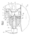
- the support 2 comprises, perpendicular to the longitudinal axis A of the pipe 2, a flat fixing face 4 in which a passage hole is made tapped 5.
- the suspension and filtration pad 3 comprises on the one hand an armature 6 metal for fixing to the vehicle body and secondly a frame metal 7 for fixing to the support 2, the frame 7 comprising for this purpose a part 8 forming a flange, pierced with a through hole 9.
- An inertial mixer 10 preferably in the form of a body of revolution, pierced with an axial passage hole 11 has an interface 12 at one end washer shape.
- the through hole 11 is a stepped hole comprising on the side of the interface 12 a portion 11a of small diameter connected by a shoulder 11b to a portion 11c of large diameter (counterbore).
- the suspension stud 3 With its armatures 6 and 7 and the mixer 10, positions the three elements on an assembly table not shown, the flange 8 being interposed between the face 4 of the support 2 fixed to the pipe 1 and the interface 12 of the mixer 10, the holes 5, 9 and 11 being aligned. Is positioned in the socket 13 of a screwdriver 14, the head 15a of a fixing screw 15 and the threaded rod 15b of the screw 15 is engaged.
- the fixing screw 15 secures in a homogeneous assembly the mixer 11 with the frame 7 of the suspension pad and filtration 3 and the exhaust support 2.
- the through hole 9 in the flange 8 of the frame 7 of the stud 3 can advantageously consist of an elongated buttonhole in a direction perpendicular to the body of the vehicle, which allows a position isostatic of the exhaust line on the assembly table, the dispersions in this direction of the exhaust pipe and the exhaust support being absorbed by the buttonhole.
- FIG. 2 differs from that of FIG. 1 by the provision, on the flange 8 of the frame 7 of the stud 3, on the side of the mixer 10, of projections 16 which, by cooperating with female imprints 17 of shape corresponding to the mixer 10, act as anti-rotation means.
- the inertial mixer could in principle present a form other than of revolution, but the form of revolution is preferable insofar as it dispenses with any indexing provision and immobilization in rotation during assembly.
- the fixing screw 15 could also include a head other than the head 15a with external impression, in which case the socket 13 of the screwdriver would be replaced by another accessory or bit or by a screwing accessory holder capable of being guided in the countersinking 11c of the hole 11 of the beater 10.
Landscapes
- Engineering & Computer Science (AREA)
- Mechanical Engineering (AREA)
- General Engineering & Computer Science (AREA)
- Chemical & Material Sciences (AREA)
- Combustion & Propulsion (AREA)
- Transportation (AREA)
- Cooling, Air Intake And Gas Exhaust, And Fuel Tank Arrangements In Propulsion Units (AREA)
- Exhaust Silencers (AREA)
Abstract
Description
Claims (7)
- Ligne d'échappement de véhicule automobile comprenant un tuyau d'échappement (1), un support d'échappement (2) fixé au tuyau d'échappement, des moyens de suspension et de filtration (3) montés entre le support d'échappement et la caisse du véhicule, et un batteur inertiel (10), caractérisée par le fait que le batteur inertiel (10) est fixé au tuyau d'échappement (1) à l'endroit du support d'échappement (2), les moyens (15) de fixation du batteur (10) au tuyau d'échappement (1) assurant également la fixation des moyens de suspension et de filtration (3) au support d'échappement (2).
- Ligne d'échappement suivant la revendication 1, caractérisée par le fait que les moyens de suspension et de filtration comprennent deux armatures (6, 7) reliées entre elles par un plot élastique (3) et l'armature (7) côté tuyau d'échappement comprend une partie formant bride (8) intercalée entre le batteur (10) et le support de d'échappement (2), le batteur, la bride et le support d'échappement étant assemblés par une vis de fixation (15).
- Ligne d'échappement suivant la revendication 2, caractérisée par le fait la vis de fixation (15) est engagée depuis le batteur (10), à travers un trou de passage (9) de la bride (8), dans un trou taraudé (5) du support d'échappement (2).
- Ligne d'échappement suivant la revendication 3, caractérisée par le fait que le trou de passage (9) dans la bride (8) est une boutonnière allongée dans une direction perpendiculaire à la caisse du véhicule.
- Ligne d'échappement suivant la revendication 3, caractérisée par le fait que le batteur (10) comporte, pour la vis de fixation (15), un trou de passage (11) étagé présentant du côté éloigné du support d'échappement (2) un lamage (11c) pour la tête (15a) de la vis.
- Ligne d'échappement suivant la revendication 5, caractérisée par le fait que le diamètre du lamage (11c) est choisi en fonction de la tête (15a) de la vis de fixation (15) et de l'accessoire de vissage (13) d'une visseuse de manière que le lamage serve de guide pour la visseuse.
- Ligne d'échappement suivant l'une quelconque des revendications 2 à 6, caractérisée par le fait que la bride (8) de l'armature (7) du plot de suspension et de filtration (3) présente, du côté du batteur (10), au moins une saillie (16) qui, en coopérant avec au moins une empreinte femelle (17) de forme correspondante du batteur (10), fait office de moyen anti-rotation.
Applications Claiming Priority (2)
| Application Number | Priority Date | Filing Date | Title |
|---|---|---|---|
| FR0112300A FR2829972B1 (fr) | 2001-09-25 | 2001-09-25 | Ligne d'echappement de vehicule automobile, comportant un batteur inertiel |
| FR0112300 | 2001-09-25 |
Publications (2)
| Publication Number | Publication Date |
|---|---|
| EP1297983A1 true EP1297983A1 (fr) | 2003-04-02 |
| EP1297983B1 EP1297983B1 (fr) | 2005-01-26 |
Family
ID=8867569
Family Applications (1)
| Application Number | Title | Priority Date | Filing Date |
|---|---|---|---|
| EP20020292251 Expired - Lifetime EP1297983B1 (fr) | 2001-09-25 | 2002-09-13 | Ligne d'échappement de véhicule automobile, comportant un batteur inertiel |
Country Status (4)
| Country | Link |
|---|---|
| EP (1) | EP1297983B1 (fr) |
| DE (1) | DE60202728T2 (fr) |
| ES (1) | ES2232721T3 (fr) |
| FR (1) | FR2829972B1 (fr) |
Families Citing this family (1)
| Publication number | Priority date | Publication date | Assignee | Title |
|---|---|---|---|---|
| FR3083580B1 (fr) | 2018-07-05 | 2021-03-19 | Renault Sas | Dispositif d'amortissement de vibrations d'un composant mecanique |
Citations (5)
| Publication number | Priority date | Publication date | Assignee | Title |
|---|---|---|---|---|
| FR2570785A1 (fr) * | 1984-09-25 | 1986-03-28 | Renault | Amortisseur de vibrations de torsion |
| FR2710381A1 (fr) * | 1993-09-23 | 1995-03-31 | Hutchinson | Batteur pour barre vibrante. |
| EP0862013A1 (fr) * | 1997-01-17 | 1998-09-02 | Hutchinson | Dispositif de suspension élastique pour tubulure d'échappement |
| FR2761730A1 (fr) * | 1997-04-04 | 1998-10-09 | Hutchinson | Suspente pour tubulure d'echappement de vehicule automobile |
| EP1132645A1 (fr) * | 2000-03-06 | 2001-09-12 | Hutchinson | Dispositif élastique de suspension d'une structure vibrante à une structure rigide |
-
2001
- 2001-09-25 FR FR0112300A patent/FR2829972B1/fr not_active Expired - Fee Related
-
2002
- 2002-09-13 EP EP20020292251 patent/EP1297983B1/fr not_active Expired - Lifetime
- 2002-09-13 DE DE2002602728 patent/DE60202728T2/de not_active Expired - Fee Related
- 2002-09-13 ES ES02292251T patent/ES2232721T3/es not_active Expired - Lifetime
Patent Citations (5)
| Publication number | Priority date | Publication date | Assignee | Title |
|---|---|---|---|---|
| FR2570785A1 (fr) * | 1984-09-25 | 1986-03-28 | Renault | Amortisseur de vibrations de torsion |
| FR2710381A1 (fr) * | 1993-09-23 | 1995-03-31 | Hutchinson | Batteur pour barre vibrante. |
| EP0862013A1 (fr) * | 1997-01-17 | 1998-09-02 | Hutchinson | Dispositif de suspension élastique pour tubulure d'échappement |
| FR2761730A1 (fr) * | 1997-04-04 | 1998-10-09 | Hutchinson | Suspente pour tubulure d'echappement de vehicule automobile |
| EP1132645A1 (fr) * | 2000-03-06 | 2001-09-12 | Hutchinson | Dispositif élastique de suspension d'une structure vibrante à une structure rigide |
Also Published As
| Publication number | Publication date |
|---|---|
| DE60202728T2 (de) | 2005-12-29 |
| EP1297983B1 (fr) | 2005-01-26 |
| DE60202728D1 (de) | 2005-03-03 |
| FR2829972B1 (fr) | 2003-12-12 |
| FR2829972A1 (fr) | 2003-03-28 |
| ES2232721T3 (es) | 2005-06-01 |
Similar Documents
| Publication | Publication Date | Title |
|---|---|---|
| EP2430321B1 (fr) | Dispositif pour fixer une premiere piece sur une deuxieme piece qui est elle-meme fixee sur une troisieme piece, assemblage de trois pieces en particulier d'un vehicule automobile | |
| EP1297983A1 (fr) | Ligne d'échappement de véhicule automobile, comportant un batteur inertiel | |
| FR3105120B1 (fr) | Fixation de dispositif de vibration sur un siège | |
| EP1794019B1 (fr) | Maintien de catalyseur par sangle sur carter cylindres | |
| FR2776606A1 (fr) | Unite d'essuie-glace | |
| JP3542949B2 (ja) | ハンドレール装置 | |
| WO2010001076A1 (fr) | Moteur d'essuie-vitre de vehicule a multiples points de fixation et structure de support dudit moteur | |
| FR3052492A1 (fr) | Palier de transmission servant de support pour une pompe a eau sur un groupe motopropulseur | |
| CN100379638C (zh) | 轻型车辆的罩支承构造 | |
| JP2003184142A (ja) | 水栓の天板に対する取付金具 | |
| FR3108691B1 (fr) | Agencement pour le montage en aveugle d'un câble de frein sur un levier d'actionnement d'un frein à tambour de véhicule automobile | |
| FR2795783A1 (fr) | Dispositif de liaison mecanique a amortissement | |
| WO2013110871A2 (fr) | Dispositif de fixation d'un groupe motopropulseur a la caisse d'un vehicule a moyen de liaison anti-couple | |
| JPH09119425A (ja) | 被取付体のねじ止め構造 | |
| EP1640620B1 (fr) | Dispositif de fixation et de filtration des vibrations, et procédé d'assemblage utilisant ce dispositif pour l'industrie automobile | |
| JPH09310735A (ja) | 自動車部材の揺動支持装置 | |
| FR2847959A1 (fr) | Dispositif antivibratoire | |
| JPH1032916A (ja) | 電線クランプ | |
| FR3058192B1 (fr) | Ensemble de collier de serrage et de fixation | |
| EP2851917B1 (fr) | Interrupteur de position | |
| CN113371110A (zh) | 后视镜及摩托车 | |
| JP2007229134A (ja) | アームレスト及びアームレストを備えた車両用シート | |
| JPH11264407A (ja) | ナット付きワッシャ及びサスペンション固定装置 | |
| FR2826411A1 (fr) | Dispositif de liaison mecanique securise | |
| JP2504934Y2 (ja) | パワ―ユニットのマウント構造 |
Legal Events
| Date | Code | Title | Description |
|---|---|---|---|
| PUAI | Public reference made under article 153(3) epc to a published international application that has entered the european phase |
Free format text: ORIGINAL CODE: 0009012 |
|
| AK | Designated contracting states |
Kind code of ref document: A1 Designated state(s): AT BE BG CH CY CZ DE DK EE ES FI FR GB GR IE IT LI LU MC NL PT SE SK TR Designated state(s): AT BE BG CH CY CZ DE DK EE ES FI FR GB GR IE IT LI LU MC NL PT SE SK TR |
|
| AX | Request for extension of the european patent |
Extension state: AL LT LV MK RO SI |
|
| 17P | Request for examination filed |
Effective date: 20030918 |
|
| AKX | Designation fees paid |
Designated state(s): BE DE ES IT |
|
| GRAP | Despatch of communication of intention to grant a patent |
Free format text: ORIGINAL CODE: EPIDOSNIGR1 |
|
| RTI1 | Title (correction) |
Free format text: AUTOMOTIVE VEHICLE EXHAUST LINE WITH INERTIAL VIBRATION DAMPENING MASS |
|
| GRAS | Grant fee paid |
Free format text: ORIGINAL CODE: EPIDOSNIGR3 |
|
| GRAA | (expected) grant |
Free format text: ORIGINAL CODE: 0009210 |
|
| AK | Designated contracting states |
Kind code of ref document: B1 Designated state(s): BE DE ES IT |
|
| REF | Corresponds to: |
Ref document number: 60202728 Country of ref document: DE Date of ref document: 20050303 Kind code of ref document: P |
|
| REG | Reference to a national code |
Ref country code: ES Ref legal event code: FG2A Ref document number: 2232721 Country of ref document: ES Kind code of ref document: T3 |
|
| PLBE | No opposition filed within time limit |
Free format text: ORIGINAL CODE: 0009261 |
|
| STAA | Information on the status of an ep patent application or granted ep patent |
Free format text: STATUS: NO OPPOSITION FILED WITHIN TIME LIMIT |
|
| 26N | No opposition filed |
Effective date: 20051027 |
|
| PGFP | Annual fee paid to national office [announced via postgrant information from national office to epo] |
Ref country code: DE Payment date: 20060926 Year of fee payment: 5 |
|
| PGFP | Annual fee paid to national office [announced via postgrant information from national office to epo] |
Ref country code: ES Payment date: 20060928 Year of fee payment: 5 |
|
| PGFP | Annual fee paid to national office [announced via postgrant information from national office to epo] |
Ref country code: IT Payment date: 20060930 Year of fee payment: 5 |
|
| PGFP | Annual fee paid to national office [announced via postgrant information from national office to epo] |
Ref country code: BE Payment date: 20061012 Year of fee payment: 5 |
|
| BERE | Be: lapsed |
Owner name: *RENAULT S.A.S. Effective date: 20070930 |
|
| PG25 | Lapsed in a contracting state [announced via postgrant information from national office to epo] |
Ref country code: DE Free format text: LAPSE BECAUSE OF NON-PAYMENT OF DUE FEES Effective date: 20080401 |
|
| PG25 | Lapsed in a contracting state [announced via postgrant information from national office to epo] |
Ref country code: BE Free format text: LAPSE BECAUSE OF NON-PAYMENT OF DUE FEES Effective date: 20070930 |
|
| REG | Reference to a national code |
Ref country code: ES Ref legal event code: FD2A Effective date: 20070914 |
|
| PG25 | Lapsed in a contracting state [announced via postgrant information from national office to epo] |
Ref country code: ES Free format text: LAPSE BECAUSE OF NON-PAYMENT OF DUE FEES Effective date: 20070914 |
|
| PG25 | Lapsed in a contracting state [announced via postgrant information from national office to epo] |
Ref country code: IT Free format text: LAPSE BECAUSE OF NON-PAYMENT OF DUE FEES Effective date: 20070913 |