EP1297896A2 - Handbetätigte Ausgabeeinrichtung für Pestizide und Herbizide - Google Patents
Handbetätigte Ausgabeeinrichtung für Pestizide und Herbizide Download PDFInfo
- Publication number
- EP1297896A2 EP1297896A2 EP02380203A EP02380203A EP1297896A2 EP 1297896 A2 EP1297896 A2 EP 1297896A2 EP 02380203 A EP02380203 A EP 02380203A EP 02380203 A EP02380203 A EP 02380203A EP 1297896 A2 EP1297896 A2 EP 1297896A2
- Authority
- EP
- European Patent Office
- Prior art keywords
- piston
- tank
- lever
- cylinder
- pumping unit
- Prior art date
- Legal status (The legal status is an assumption and is not a legal conclusion. Google has not performed a legal analysis and makes no representation as to the accuracy of the status listed.)
- Withdrawn
Links
Images


Classifications
-
- B—PERFORMING OPERATIONS; TRANSPORTING
- B05—SPRAYING OR ATOMISING IN GENERAL; APPLYING FLUENT MATERIALS TO SURFACES, IN GENERAL
- B05B—SPRAYING APPARATUS; ATOMISING APPARATUS; NOZZLES
- B05B9/00—Spraying apparatus for discharge of liquids or other fluent material, without essentially mixing with gas or vapour
- B05B9/03—Spraying apparatus for discharge of liquids or other fluent material, without essentially mixing with gas or vapour characterised by means for supplying liquid or other fluent material
- B05B9/04—Spraying apparatus for discharge of liquids or other fluent material, without essentially mixing with gas or vapour characterised by means for supplying liquid or other fluent material with pressurised or compressible container; with pump
- B05B9/08—Apparatus to be carried on or by a person, e.g. of knapsack type
- B05B9/085—Apparatus to be carried on or by a person, e.g. of knapsack type with a liquid pump
- B05B9/0877—Apparatus to be carried on or by a person, e.g. of knapsack type with a liquid pump the pump being of pressure-accumulation type or being connected to a pressure accumulation chamber
-
- A—HUMAN NECESSITIES
- A01—AGRICULTURE; FORESTRY; ANIMAL HUSBANDRY; HUNTING; TRAPPING; FISHING
- A01M—CATCHING, TRAPPING OR SCARING OF ANIMALS; APPARATUS FOR THE DESTRUCTION OF NOXIOUS ANIMALS OR NOXIOUS PLANTS
- A01M7/00—Special adaptations or arrangements of liquid-spraying apparatus for purposes covered by this subclass
- A01M7/0003—Atomisers or mist blowers
- A01M7/0017—Portable atomisers, e.g. knapsack type
Definitions
- the present invention relates to a lever-actuated manual sprayer, of those known as backpack sprayers, which is provided with a tank containing the product to be sprayed and a pumping unit actuated by a manual lever, as well as straps for securing the unit on the user's back.
- the object of the invention is to provide a unit of the aforementioned type for spraying phytosanitary liquids and leaf and herbicidal applications on fruit, horticultural, cereal, leguminous etc. crops, as well as in parks and gardens, which equipment incorporates a number of improvements over conventional ones concerning the ergonomics of the tank and the interchangeable lever mounting system, as well as the pumping unit as a whole and even the means for assembling and removing the support straps, resulting in a greater comfort for the user and a more efficient and better operation.
- Lever-actuated sprayers used in phytosanitary and other applications, and specifically backpack type sprayers are basically comprised of: a tank containing the product to be sprayed; a pumping system based on a piston mounted above a cylinder with valves and a product suction duct; a manually operated lever; and the corresponding support straps and other means and components that complete the equipment to enable its operation.
- Certain sprayers of this type have a tank designed with ergonomic areas on both sides to conform to the user's back, although these areas generally do not encompass the entire area of contact with the back. In general, this is a band of material in the lumbar zone with a certain curvature, so that the other areas in contact with the back (shoulder blades, area above the lumbar zone, column, etc.) has no adaptation considered to the anatomical shape, in general having a lumbar support on one or both sides.
- Units provided with a mobile shaft have a complex operation for changing the rotation axis, as manual tools are needed, so that the shaft must be changed by the distributor of the product, who must modify a right-handed product upon a request for a left-handed one.
- the distributor of the product who must modify a right-handed product upon a request for a left-handed one.
- Another aspect to consider is the difficulty encountered with conventional sprayers for assembling and removing the sprayer support straps in order to perform an operative change in the equipment.
- the pumping group has a number of disadvantages, among which is that the suction duct for the product to be sprayed runs inside the chamber formed by the corresponding piston, the duct in turn being mounted on the lid of the piston to then secure the lid indestructibly to the piston body.
- the result is that in the event of a poor assembly or welding of the duct, or wear due to occlusion, etc., the entire piston must be replaced by a new assembly and it is not possible to replace only the suction duct.
- malfunctions of the suction duct can occur gradually: before its final failure the user may have suffered a reduced performance for a long time without being aware of it, as it is not possible after all to detect a physical damage in the connection of a part that is concealed inside the piston.
- the sprayer disclosed has been designed to solve all the aforementioned problems by means of a number of improvements affecting certain parts and components of the equipment.
- one of the improvements of the invention consists of the tank having an external surface with a double curvature, to determine a double curvature that resembles that of the user's back: in one case the classically determined curvature in a horizontal sense (the curvature being contained in a plane parallel to the ground) and in the other case the one defined in an upwards sense by the backbone in the upright and forward working position, with the centers of both curvatures being in the in the virtual plane of symmetry, at a certain distance in front of it.
- the tank of the invention has a bi-directional ergonomic configuration that allows its perfect adaptation to the user's back, reducing the user's fatigue and simplifying the operation of the pumping group, which is easily actuated with either hand by simply changing the position of the lever.
- Another improvement of the invention, specifically related to the tank, is that the lower part of said tank is provided with support legs that, in addition to providing a great sturdiness to the lower part of the tank allow a correct stabilization of the equipment when it rests directly on the ground.
- said legs are provided with openings for a simple assembly and removal of the corresponding actuation lever, such that the tank is obtained by the mold insert technique with the legs being produced independently in an injection mold and later inserted in each of the four corners of the base of the tank mold, so that the tank itself is constructed with the legs fully integrated.
- Another novel characteristic that also affects the tank is that incorporation of the aforementioned legs results in a tank that is raised a certain height above the ground, enabling the disposition of a collection duct at the central lower area of the tank that concentrates the residual liquid towards the corresponding pump piston.
- Another improvement or novel characteristic of the invention relates to the means for attaching the straps with which the equipment is held on the user's back, and that allow a simple and fast change of the operational mode of the equipment.
- the top part is characterized in that its extraction, and therefore that of the folded strap, is performed with the aid of a double handle that allows the user to remove the folded strap from its position with a simple pushing and extraction movement, so that between the two handles there is enough space to extract the folded strap and to place it, without time being wasted, in the same orifice but from the opposite side of the tank.
- the piston-cylinder assembly is characterized in that the corresponding duct for suctioning the product from the corresponding pressure chamber to the outlet orifice is externally connected to the piston body by means of two coupling zones, one defined by a cavity established tightly on the piston lid and through which the product will travel towards the outlet, and another zone defined by a cavity, also tightly fitted that establishes connection with the lower area of the piston and which will receive the product retained under pressure in the corresponding chamber.
- the suction duct becomes an easily replaceable component, without requiring to discard the piston and allowing to perceive easily possible leaks or malfunctions as it is not enclosed in the piston chamber, as is conventional.
- the shaft-chamber conformation is determined by two non-concentric cylinders, so that the suction duct is disposed aligned along the entire piston and partially concealed inside a channel placed in the area of greatest diameter of the piston, which channel is not subjected to any internal pressure but simply constitutes a guide for the suction duct towards an upper anchoring on the piston lid, with the lower segment of said duct being fully exposed to allow its handling but adjacent to the part of lesser diameter of the piston that acts as a shaft.
- Another improvement of the invention affects the cylinder on which the piston itself is mounted, which cylinder projects upwards to embrace the entire piston, including the chamber defined by it, attaching said cylinder to the corresponding upper orifice of the tank where the sealing problem is easily solved, such that the cylinder is comprised of two non-concentric parts joined tangentially by one of their generating lines, one on the top with a size suitable for circulation of the piston, with a flange on its end to rest on the upper orifice of the tank, and another lower part in which is housed the feeding duct and the cylinder of the shaft of the piston, with a diameter adjusted to ensure a tight fit with a retainer provided for such purpose.
- the aforementioned cylinder of the piston is housed in a neck determined by an opening made for such purpose in the top of the tank, and is secured by a bolt without requiring any internal attachment to the tank that would compromise its tightness, so that on its bottom a base filter is fitted that in addition to performing the filtering function prevents the axial movement of the pumping unit.
- the tight fit and centering of the piston is achieved by means of a ring of soft material with a low coefficient of friction, positioned above the cylinder and locked in place around it by the displacement towards said cylinder of the aforementioned ring as a result of the compression caused by the bolt attaching the cylinder to the piston.
- Said ring also ensures tightness of the tank in the area, preventing liquid from leaking accidentally through the opening or orifice provided on the top of the tank to house the entire pumping unit.
- Another improvement of the invention corresponds to the assembly of the actuation lever, which is designed so that it can be changed without any difficulty from one side to another, that is, so that the equipment can be used by both right-handed and left-handed persons.
- the assembly of the connecting rod that relates the top of the equipment to the actuation lever is also a novelty, consisting of a part that is provided on the top lid of the pumping unit that includes an open cylinder to which the vertical segment of the connecting rod is attached and a pair of concentric passages where a horizontal segment of said connecting rod is positioned, so that said rod is secured without requiring bolts or pins and is attached to the lever by a simple pin.
- the lever On its part, the lever is mounted on the tank at the bottom end of the latter, at a horizontal segment of said lever that is positioned in corresponding passages provided for such purpose in one pair of the four legs provided for such purpose on the bottom of the tank; that is, on the pair of legs located in correspondence with the edge near one of the sides, allowing to change the position of the lever to establish it in the passages provided on the other two legs so that an ambidextrous use is made possible.
- the lever in the vertical position the lever can be extracted by opposing protrusions of it in the form of keys with keyslots established in the corresponding legs, while when the lever is not vertical the protrusions will meet against the legs, preventing the accidental disassembly of the lever.
- Another improvement of the sprayer of the invention relates to the assembly of the filter provided on the bottom and on which the pumping unit rests.
- This filter is not only a support for the pumping unit with respect to the tank to prevent the axial displacement of the assembly, but also acts as a filter for particles that may eventually block the pumping unit, and is also used to house and retain an intake valve for the liquid or product from the tank to the compression chamber.
- the equipment is complemented by a stirrer placed inside the tank, which is provided with a hexagonal protrusion defining an improvised Allen wrench that facilitates tightening and loosening of a nut meant to hold the corresponding retainer in the piston, as well as to house the compression valve for the assembly.
- the stirrer is provided on its upper end with a sort of dovetail-shaped heel for its assembly on a complementary configuration provided on the body of the pumping unit, with the aforementioned stirrer being tightly fitted to the piston in a sense perpendicular to the latter's oscillatory motion, thereby preventing an accidental dislodgement while it is in operation.
- Said stirrer has a configuration with an optimized sigmoid profile in order to generate a fluid circulation flow during pumping that facilitates the solution of product particles.
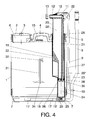
- the sprayer equipment of the invention is comprised of a tank (1) containing the product to be sprayed, above which is established a discharge nozzle with a corresponding lid (2), provided with an air suction and spill-proof valve (3), with a microperforated filter (6) being provided on said nozzle.
- the tank On the bottom part, almost at its corners, the tank is provided with corresponding solid legs (7) that are obtained independently by injection and are placed in the mold with which the tank itself is formed by molding, so that the legs (7) are integrated on the bottom of the tank and constitute a reinforcement of its bottom as well as having other functions that will be described further below.
- the equipment is also provided with a manually actuated lever (8) that is attached to a connecting rod (9) by means of a lower segment (10) of said rod (9) which passes through a transverse orifice of the lever (8), secured by a pin, while on the top the connecting rod (9) is attached to a part (11) mounted on the top lid (12) of the piston (20) that is part of the pumping unit.
- Said top lid (12) is provided with a securing nut (13) for the rubber tube that leads the product to be sprayed to the spray nozzle.
- the tank (1) as shown in figures 2 and 3, has a fully ergonomic configuration on both of its sides, so that it has a transverse curvature and a longitudinal curvature, in order to conform perfectly to the corresponding areas of the back of the user.
- the actuation lever (8) is designed so that its position can be changed quickly, that is, so that it can be used with optimal movements by both right-handed and left-handed persons.
- the fast assembly and removal system is based on the fact that the orifices (7'), provided in the solid legs (7) for housing the horizontal segment of the lever (8), have a keyslot which can be set opposite a protrusion (14) provided in said horizontal segment of the lever (8), such that in the vertical position of the latter the protrusions (14) are placed opposite the keyslots established in the orifices (7') of the legs (7), at which time if the connecting rod (9) is disengaged from the lever (8) simply by removing the pin housed in the outer segment (10) of said rod (9), it is possible by pulling outwards on the lever (8) to remove it and assemble it on the orifices (7'') of the opposite side, as long as it is vertical; after it is mounted the lever (8) and the connecting rod (9) are again connected to each other so that when the
- the means of passage for said straps consist of a part (15) placed on both the top part (main strap) and on the sides of the lower part (optional lumbar strap), through which parts the straps are passed folded and extracted by a double handle (16) that allows the user to remove the folded strap from its housing by simply pressing and pulling on it. Enough space is left between the two handles (16) to allow extracting the folded strap and placing it again in the same passage, introducing it from the opposite side of the device.
- the pumping unit comprises a cylinder (19) on which is mounted a piston (20) with a longitudinal channel (21) that is displaced from its geometrical axis, with the channel (21) being placed collaterally for assembling and guiding the corresponding suction duct (22) of the sprayer unit, with said duct (22) mounted between the top lid (12) of the piston (20) or pumping unit itself and a cavity or housing (23) provided on the bottom of said piston (20), such that it is possible to see that the latter is provided with a top segment (20') that has a greater diameter that a lower segment (20").
- suction duct (22) is connected externally to the body of the piston (20) at the two extremal coupling areas described above, one corresponding to the top part belonging to the lid (12) and another corresponding to the lower housing (23) formed for such purpose of the piston (20).
- the cylinder (19) is inferiorly provided with a segment (19') with a smaller diameter in which is established the corresponding compression chamber (24), on the bottom of which is provided a check valve (25) that prevents the passage of the product from the tank to said chamber (24); there is a second valve (26) on the lower segment of the piston (20'') that remains closed while the product is entering the compression chamber (24).
- the suction duct (22) is aligned along the entire piston (20), remaining concealed in the channel (21) of said piston, such that the lower segment of said suction duct (22) is free, as labeled (27), allowing to access it and be easily changed.
- the area of assembly of the valves (25) and (26) and the area of the top lid (12) are provided with the corresponding sealing means to ensure a leak-proof pumping operation.
- the cylinder (19) is mounted on the neck of an opening provided for such purpose on the upper part of the tank (1), with said cylinder (19) being locked in place by the aforementioned nut (5), so that the adjustment and perfect centering of the piston (20) on the cylinder (19) is achieved by a ring (28) of a soft material positioned on the top of the cylinder (19), with the ring (28) being trapped against the lateral surface of the piston (20) as a result of the force exerted by tightening the nut (5).
- the lower part of the pumping unit rests on a filter (29) that is housed in a recess (30) established for such purpose in the bottom part of the tank, as shown in figure 6, with the filter (29) also determining a means for housing and retaining the intake valve (25).
- stirrer (31) having a sigmoid shaped profile that allows generating a fluid circulation flow during the pumping to facilitate the solution of product particles.
- the stirrer (31) is provided on its top end with a dovetail shaped heel (32) complementary of a housing (33) provided for it in the piston (20) or the pumping unit, and oriented perpendicularly to the oscillatory motion of the piston (20), making it unlikely that it will accidentally disengage while in operation.
- the bottom part of said stirrer (31) is provided with a hexagonal protrusion (34) that acts as an improvised key to facilitate the screwing on and off of a part (35) that, in addition to housing the valve (26), keeps the corresponding retainer (36) on the piston (20).
Landscapes
- Life Sciences & Earth Sciences (AREA)
- Engineering & Computer Science (AREA)
- Insects & Arthropods (AREA)
- Pest Control & Pesticides (AREA)
- Wood Science & Technology (AREA)
- Zoology (AREA)
- Environmental Sciences (AREA)
- Catching Or Destruction (AREA)
- Containers And Packaging Bodies Having A Special Means To Remove Contents (AREA)
Applications Claiming Priority (2)
| Application Number | Priority Date | Filing Date | Title |
|---|---|---|---|
| ES200102181A ES2224762B1 (es) | 2001-09-28 | 2001-09-28 | Equipo pulverizador manual para pesticidas y herbicidas. |
| ES200102181 | 2001-09-28 |
Publications (2)
| Publication Number | Publication Date |
|---|---|
| EP1297896A2 true EP1297896A2 (de) | 2003-04-02 |
| EP1297896A3 EP1297896A3 (de) | 2005-08-17 |
Family
ID=8499047
Family Applications (1)
| Application Number | Title | Priority Date | Filing Date |
|---|---|---|---|
| EP02380203A Withdrawn EP1297896A3 (de) | 2001-09-28 | 2002-09-27 | Handbetätigte Ausgabeeinrichtung für Pestizide und Herbizide |
Country Status (4)
| Country | Link |
|---|---|
| EP (1) | EP1297896A3 (de) |
| BR (1) | BR0206210A (de) |
| CO (1) | CO5380023A1 (de) |
| ES (1) | ES2224762B1 (de) |
Cited By (14)
| Publication number | Priority date | Publication date | Assignee | Title |
|---|---|---|---|---|
| ES2385968A1 (es) * | 2012-03-06 | 2012-08-06 | Goizper, S. Coop. | Aplicador de fluidos con capacidad de dosificacion |
| CN101745483B (zh) * | 2009-12-18 | 2013-11-20 | 魏华春 | 具有吸水功能的喷雾器 |
| US8960649B2 (en) | 2010-07-29 | 2015-02-24 | Guarany Indústria E Comércio Ltda. | Joystick control for backpack sprayer |
| CN108347913A (zh) * | 2015-11-04 | 2018-07-31 | 住友化学株式会社 | 驱动装置及使用该驱动装置的喷雾装置 |
| CN111011331A (zh) * | 2018-10-10 | 2020-04-17 | 蔡平制造业公司 | 按需混合的智能背包式喷洒器 |
| JP2021013913A (ja) * | 2019-07-16 | 2021-02-12 | 株式会社麻場 | 吊金具取付構造 |
| CN112514880A (zh) * | 2020-12-07 | 2021-03-19 | 浙江陆雄建鑫农业机械有限公司 | 一种喷雾机及其扇型喷杆 |
| CN112690263A (zh) * | 2020-10-14 | 2021-04-23 | 田丰 | 一种生物农药喷洒装置 |
| CN113080177A (zh) * | 2021-03-24 | 2021-07-09 | 高波 | 一种农作物种植用自走式喷杆喷雾机及其使用方法 |
| CN114287412A (zh) * | 2021-12-30 | 2022-04-08 | 浙江三骐科技有限公司 | 一种电动喷雾器 |
| CN114504908A (zh) * | 2022-02-25 | 2022-05-17 | 叶松 | 一种便于安装拆卸的建筑工地喷雾机 |
| CN114643150A (zh) * | 2022-03-18 | 2022-06-21 | 市下控股有限公司 | 一种背负式喷雾器药箱口密封结构及瓶口定型工艺 |
| CN115299374A (zh) * | 2022-09-07 | 2022-11-08 | 漳浦县赵木兰养殖有限公司 | 一种用于后备猪诱情期的设备 |
| CN115336569A (zh) * | 2022-09-02 | 2022-11-15 | 安徽辰昌建设有限公司 | 一种公路绿化养护装置 |
Family Cites Families (10)
| Publication number | Priority date | Publication date | Assignee | Title |
|---|---|---|---|---|
| FR745213A (de) * | 1933-05-06 | |||
| GB201280A (en) * | 1922-05-10 | 1923-08-02 | Henry Milward & Sons Ltd | Improvements relating to liquid spray pumps or apparatus |
| US3034686A (en) * | 1960-02-18 | 1962-05-15 | Santarelli Vincent | Sprayer with pump and screen |
| US3239109A (en) * | 1964-10-26 | 1966-03-08 | Santarelli Vincent | Sprayer pump |
| DE1653638A1 (de) * | 1966-07-11 | 1971-07-22 | Tecnoma | Rueckenzerstaeuber mit einer mittels eines Schwenkhebels betaetigten Pumpe |
| AT355858B (de) * | 1976-05-12 | 1980-03-25 | Keller Kg Wilhelm | Spritzvorrichtung fuer fluessigkeiten |
| ES2024847A6 (es) * | 1990-06-08 | 1992-03-01 | Coop Goizper S | Mejoras en pulverizadores de palanca a presion retenida. |
| ES2054544B1 (es) * | 1992-01-10 | 1997-02-16 | Coop Goizper S | Mejoras introducidas en pulverizadores de productos fitosanitarios. |
| ES1025527Y (es) * | 1993-08-23 | 1994-07-16 | Coop Goizper S | Tanque fitosanitario |
| US5755361A (en) * | 1996-01-11 | 1998-05-26 | The Fountainhead Group, Inc. | Pump sprayer |
-
2001
- 2001-09-28 ES ES200102181A patent/ES2224762B1/es not_active Expired - Fee Related
-
2002
- 2002-09-26 CO CO02086714A patent/CO5380023A1/es not_active Application Discontinuation
- 2002-09-27 EP EP02380203A patent/EP1297896A3/de not_active Withdrawn
- 2002-09-30 BR BR0206210-0A patent/BR0206210A/pt not_active IP Right Cessation
Non-Patent Citations (1)
| Title |
|---|
| None |
Cited By (19)
| Publication number | Priority date | Publication date | Assignee | Title |
|---|---|---|---|---|
| CN101745483B (zh) * | 2009-12-18 | 2013-11-20 | 魏华春 | 具有吸水功能的喷雾器 |
| US8960649B2 (en) | 2010-07-29 | 2015-02-24 | Guarany Indústria E Comércio Ltda. | Joystick control for backpack sprayer |
| ES2385968A1 (es) * | 2012-03-06 | 2012-08-06 | Goizper, S. Coop. | Aplicador de fluidos con capacidad de dosificacion |
| CN108347913A (zh) * | 2015-11-04 | 2018-07-31 | 住友化学株式会社 | 驱动装置及使用该驱动装置的喷雾装置 |
| CN108347913B (zh) * | 2015-11-04 | 2021-03-12 | 住友化学株式会社 | 驱动装置及使用该驱动装置的喷雾装置 |
| CN111011331A (zh) * | 2018-10-10 | 2020-04-17 | 蔡平制造业公司 | 按需混合的智能背包式喷洒器 |
| JP2021013913A (ja) * | 2019-07-16 | 2021-02-12 | 株式会社麻場 | 吊金具取付構造 |
| CN112690263A (zh) * | 2020-10-14 | 2021-04-23 | 田丰 | 一种生物农药喷洒装置 |
| CN112514880A (zh) * | 2020-12-07 | 2021-03-19 | 浙江陆雄建鑫农业机械有限公司 | 一种喷雾机及其扇型喷杆 |
| CN112514880B (zh) * | 2020-12-07 | 2022-04-19 | 浙江陆雄建鑫农业机械有限公司 | 一种喷雾机及其扇型喷杆 |
| CN113080177A (zh) * | 2021-03-24 | 2021-07-09 | 高波 | 一种农作物种植用自走式喷杆喷雾机及其使用方法 |
| CN114287412A (zh) * | 2021-12-30 | 2022-04-08 | 浙江三骐科技有限公司 | 一种电动喷雾器 |
| CN114504908A (zh) * | 2022-02-25 | 2022-05-17 | 叶松 | 一种便于安装拆卸的建筑工地喷雾机 |
| CN114504908B (zh) * | 2022-02-25 | 2023-08-22 | 江苏宜安建设有限公司 | 一种便于安装拆卸的建筑工地喷雾机 |
| CN114643150A (zh) * | 2022-03-18 | 2022-06-21 | 市下控股有限公司 | 一种背负式喷雾器药箱口密封结构及瓶口定型工艺 |
| CN115336569A (zh) * | 2022-09-02 | 2022-11-15 | 安徽辰昌建设有限公司 | 一种公路绿化养护装置 |
| CN115336569B (zh) * | 2022-09-02 | 2023-12-01 | 安徽辰昌建设有限公司 | 一种公路绿化养护装置 |
| CN115299374A (zh) * | 2022-09-07 | 2022-11-08 | 漳浦县赵木兰养殖有限公司 | 一种用于后备猪诱情期的设备 |
| CN115299374B (zh) * | 2022-09-07 | 2023-08-01 | 漳浦县赵木兰养殖有限公司 | 一种用于后备猪诱情期的设备 |
Also Published As
| Publication number | Publication date |
|---|---|
| EP1297896A3 (de) | 2005-08-17 |
| ES2224762B1 (es) | 2007-06-16 |
| CO5380023A1 (es) | 2004-03-31 |
| BR0206210A (pt) | 2004-08-10 |
| ES2224762A1 (es) | 2005-03-01 |
Similar Documents
| Publication | Publication Date | Title |
|---|---|---|
| EP1297896A2 (de) | Handbetätigte Ausgabeeinrichtung für Pestizide und Herbizide | |
| US5984199A (en) | Backpack sprayer with an expandable accumulator chamber | |
| US9079200B2 (en) | Multi-container backpack style sprayer | |
| US20170106385A1 (en) | Portable pressurized sprayer | |
| US10766046B2 (en) | Mix on demand smart backpack sprayer with removable concentrate tank | |
| US20060261181A1 (en) | Backpack sprayer | |
| EP1872657A1 (de) | Tragbare landwirtschaftliche spritzvorrichtung | |
| US5150837A (en) | Backpack spraying equipment | |
| US4984742A (en) | Container and pump assembly | |
| US20090320751A1 (en) | Texture sprayer | |
| US10994294B2 (en) | Backpack sprayer with selectable internal pump | |
| CN101027135A (zh) | 用于多容器喷雾系统的具有车辆轮胎阀型加压元件的盖 | |
| US20150238987A1 (en) | Backpack Sprayer | |
| KR20150047175A (ko) | 농약 분무기 | |
| WO2022007498A1 (zh) | 喷枪 | |
| EP2364104B1 (de) | Verteiler für automatischen sprüher | |
| US4557669A (en) | Pumping apparatus | |
| US6588929B1 (en) | Portable mixing and dispensing apparatus and method | |
| KR101948585B1 (ko) | 상단과 하단이 탈부착되며, 농약분무방향이 유연한 농약 분무기통 | |
| US10471453B2 (en) | Pump suction/expulsion for liquids and gases versatile | |
| KR20240000442A (ko) | 가압식 분무기 | |
| KR102634891B1 (ko) | 충전식 자동 휴대 분무기 | |
| CN211746443U (zh) | 一种农业种植喷药设备 | |
| CN216906579U (zh) | 一种景观养护用打药装置 | |
| US20210394207A1 (en) | Sprayer apparatus with removable solution container |
Legal Events
| Date | Code | Title | Description |
|---|---|---|---|
| PUAI | Public reference made under article 153(3) epc to a published international application that has entered the european phase |
Free format text: ORIGINAL CODE: 0009012 |
|
| AK | Designated contracting states |
Kind code of ref document: A2 Designated state(s): AT BE BG CH CY CZ DE DK EE ES FI FR GB GR IE IT LI LU MC NL PT SE SK TR Designated state(s): AT BE BG CH CY CZ DE DK EE ES FI FR GB GR IE IT LI LU MC NL PT SE SK TR |
|
| AX | Request for extension of the european patent |
Extension state: AL LT LV MK RO SI |
|
| PUAL | Search report despatched |
Free format text: ORIGINAL CODE: 0009013 |
|
| AK | Designated contracting states |
Kind code of ref document: A3 Designated state(s): AT BE BG CH CY CZ DE DK EE ES FI FR GB GR IE IT LI LU MC NL PT SE SK TR |
|
| AX | Request for extension of the european patent |
Extension state: AL LT LV MK RO SI |
|
| 17P | Request for examination filed |
Effective date: 20060216 |
|
| AKX | Designation fees paid |
Designated state(s): AT BE BG CH CY CZ DE DK EE ES FI FR GB GR IE IT LI LU MC NL PT SE SK TR |
|
| GRAP | Despatch of communication of intention to grant a patent |
Free format text: ORIGINAL CODE: EPIDOSNIGR1 |
|
| STAA | Information on the status of an ep patent application or granted ep patent |
Free format text: STATUS: THE APPLICATION IS DEEMED TO BE WITHDRAWN |
|
| 18D | Application deemed to be withdrawn |
Effective date: 20080701 |