EP1297804A2 - Vorrichtung zum Ausschneiden eines Artikels aus einem langen Band und zum Anhaften eines Artikels an einem Klebeband - Google Patents
Vorrichtung zum Ausschneiden eines Artikels aus einem langen Band und zum Anhaften eines Artikels an einem Klebeband Download PDFInfo
- Publication number
- EP1297804A2 EP1297804A2 EP02256744A EP02256744A EP1297804A2 EP 1297804 A2 EP1297804 A2 EP 1297804A2 EP 02256744 A EP02256744 A EP 02256744A EP 02256744 A EP02256744 A EP 02256744A EP 1297804 A2 EP1297804 A2 EP 1297804A2
- Authority
- EP
- European Patent Office
- Prior art keywords
- roll
- pad
- article
- adhering
- adhesive tape
- Prior art date
- Legal status (The legal status is an assumption and is not a legal conclusion. Google has not performed a legal analysis and makes no representation as to the accuracy of the status listed.)
- Granted
Links
Images
Classifications
-
- A—HUMAN NECESSITIES
- A61—MEDICAL OR VETERINARY SCIENCE; HYGIENE
- A61F—FILTERS IMPLANTABLE INTO BLOOD VESSELS; PROSTHESES; DEVICES PROVIDING PATENCY TO, OR PREVENTING COLLAPSING OF, TUBULAR STRUCTURES OF THE BODY, e.g. STENTS; ORTHOPAEDIC, NURSING OR CONTRACEPTIVE DEVICES; FOMENTATION; TREATMENT OR PROTECTION OF EYES OR EARS; BANDAGES, DRESSINGS OR ABSORBENT PADS; FIRST-AID KITS
- A61F13/00—Bandages or dressings; Absorbent pads
- A61F13/02—Adhesive bandages or dressings
- A61F13/0276—Apparatus or processes for manufacturing adhesive dressings or bandages
- A61F13/0279—Apparatus or processes for manufacturing adhesive dressings or bandages by attaching individual patches on moving webs
-
- Y—GENERAL TAGGING OF NEW TECHNOLOGICAL DEVELOPMENTS; GENERAL TAGGING OF CROSS-SECTIONAL TECHNOLOGIES SPANNING OVER SEVERAL SECTIONS OF THE IPC; TECHNICAL SUBJECTS COVERED BY FORMER USPC CROSS-REFERENCE ART COLLECTIONS [XRACs] AND DIGESTS
- Y10—TECHNICAL SUBJECTS COVERED BY FORMER USPC
- Y10T—TECHNICAL SUBJECTS COVERED BY FORMER US CLASSIFICATION
- Y10T156/00—Adhesive bonding and miscellaneous chemical manufacture
- Y10T156/12—Surface bonding means and/or assembly means with cutting, punching, piercing, severing or tearing
- Y10T156/1317—Means feeding plural workpieces to be joined
- Y10T156/1322—Severing before bonding or assembling of parts
- Y10T156/133—Delivering cut part to indefinite or running length web
-
- Y—GENERAL TAGGING OF NEW TECHNOLOGICAL DEVELOPMENTS; GENERAL TAGGING OF CROSS-SECTIONAL TECHNOLOGIES SPANNING OVER SEVERAL SECTIONS OF THE IPC; TECHNICAL SUBJECTS COVERED BY FORMER USPC CROSS-REFERENCE ART COLLECTIONS [XRACs] AND DIGESTS
- Y10—TECHNICAL SUBJECTS COVERED BY FORMER USPC
- Y10T—TECHNICAL SUBJECTS COVERED BY FORMER US CLASSIFICATION
- Y10T156/00—Adhesive bonding and miscellaneous chemical manufacture
- Y10T156/17—Surface bonding means and/or assemblymeans with work feeding or handling means
- Y10T156/1702—For plural parts or plural areas of single part
- Y10T156/1712—Indefinite or running length work
- Y10T156/1734—Means bringing articles into association with web
-
- Y—GENERAL TAGGING OF NEW TECHNOLOGICAL DEVELOPMENTS; GENERAL TAGGING OF CROSS-SECTIONAL TECHNOLOGIES SPANNING OVER SEVERAL SECTIONS OF THE IPC; TECHNICAL SUBJECTS COVERED BY FORMER USPC CROSS-REFERENCE ART COLLECTIONS [XRACs] AND DIGESTS
- Y10—TECHNICAL SUBJECTS COVERED BY FORMER USPC
- Y10T—TECHNICAL SUBJECTS COVERED BY FORMER US CLASSIFICATION
- Y10T156/00—Adhesive bonding and miscellaneous chemical manufacture
- Y10T156/17—Surface bonding means and/or assemblymeans with work feeding or handling means
- Y10T156/1702—For plural parts or plural areas of single part
- Y10T156/1744—Means bringing discrete articles into assembled relationship
- Y10T156/1768—Means simultaneously conveying plural articles from a single source and serially presenting them to an assembly station
- Y10T156/1771—Turret or rotary drum-type conveyor
-
- Y—GENERAL TAGGING OF NEW TECHNOLOGICAL DEVELOPMENTS; GENERAL TAGGING OF CROSS-SECTIONAL TECHNOLOGIES SPANNING OVER SEVERAL SECTIONS OF THE IPC; TECHNICAL SUBJECTS COVERED BY FORMER USPC CROSS-REFERENCE ART COLLECTIONS [XRACs] AND DIGESTS
- Y10—TECHNICAL SUBJECTS COVERED BY FORMER USPC
- Y10T—TECHNICAL SUBJECTS COVERED BY FORMER US CLASSIFICATION
- Y10T83/00—Cutting
- Y10T83/04—Processes
- Y10T83/0524—Plural cutting steps
- Y10T83/0529—Blanking and cutting
-
- Y—GENERAL TAGGING OF NEW TECHNOLOGICAL DEVELOPMENTS; GENERAL TAGGING OF CROSS-SECTIONAL TECHNOLOGIES SPANNING OVER SEVERAL SECTIONS OF THE IPC; TECHNICAL SUBJECTS COVERED BY FORMER USPC CROSS-REFERENCE ART COLLECTIONS [XRACs] AND DIGESTS
- Y10—TECHNICAL SUBJECTS COVERED BY FORMER USPC
- Y10T—TECHNICAL SUBJECTS COVERED BY FORMER US CLASSIFICATION
- Y10T83/00—Cutting
- Y10T83/202—With product handling means
- Y10T83/2066—By fluid current
- Y10T83/207—By suction means
-
- Y—GENERAL TAGGING OF NEW TECHNOLOGICAL DEVELOPMENTS; GENERAL TAGGING OF CROSS-SECTIONAL TECHNOLOGIES SPANNING OVER SEVERAL SECTIONS OF THE IPC; TECHNICAL SUBJECTS COVERED BY FORMER USPC CROSS-REFERENCE ART COLLECTIONS [XRACs] AND DIGESTS
- Y10—TECHNICAL SUBJECTS COVERED BY FORMER USPC
- Y10T—TECHNICAL SUBJECTS COVERED BY FORMER US CLASSIFICATION
- Y10T83/00—Cutting
- Y10T83/465—Cutting motion of tool has component in direction of moving work
- Y10T83/4766—Orbital motion of cutting blade
- Y10T83/4769—Work feeder mounted on tool support
- Y10T83/4772—Gripper-type feeder
-
- Y—GENERAL TAGGING OF NEW TECHNOLOGICAL DEVELOPMENTS; GENERAL TAGGING OF CROSS-SECTIONAL TECHNOLOGIES SPANNING OVER SEVERAL SECTIONS OF THE IPC; TECHNICAL SUBJECTS COVERED BY FORMER USPC CROSS-REFERENCE ART COLLECTIONS [XRACs] AND DIGESTS
- Y10—TECHNICAL SUBJECTS COVERED BY FORMER USPC
- Y10T—TECHNICAL SUBJECTS COVERED BY FORMER US CLASSIFICATION
- Y10T83/00—Cutting
- Y10T83/465—Cutting motion of tool has component in direction of moving work
- Y10T83/4766—Orbital motion of cutting blade
- Y10T83/4795—Rotary tool
- Y10T83/483—With cooperating rotary cutter or backup
- Y10T83/4836—With radial overlap of the cutting members
Definitions
- the present invention relates to a device for cutting out an article from a long tape and adhering the article on an adhesive tape. Further the present invention relates to a device for cutting and adhering pads having a variety of shapes, in particular, to a compact device for cutting and adhering capable of mass production of a pad without occupying a large area or volume for setting.
- the device of the present invention for cutting and adhering a pad is, in particular, suitable for cutting and adhering a pad for dressing, adhesive bandage and the like.
- a continuous production device of adhesive bandage including a process of cutting a pad and a process of sequentially adhering the pad at predetermined intervals
- a continuous production device of adhesive bandage including a process of cutting an adhesive bandage using a rotary die cutter and a process of sequentially delivering the cut adhesive bandage to a transfer machine while holding the adhesive bandage by suction
- a continuous method and device for adhering a pad to an adhesive film including processes comprising receiving a pad which has been cut in predetermined dimensions at a pad receiving position and broadening a spacing between adjacent pads by continuously accelerating transferring rate during continuous transfer of the pad aligned in a predetermined orientation
- a continuous method and device for adhering pad to adhesive film including processes comprising receiving a pad which has been cut in a predetermined dimension at a pad receiving position and continuously transferring a pad at a constant rate and adhering the pad to an adhesive surface of a long adhesive tape which moves faster than the pad transfer speed
- a continuous method and device for adhering a pad to a long adhesive film including processes comprising transferring a pad which has been cut at predetermined dimensions at a constant rate while holding the pad by sucking arranged at a spacing corresponding to a distance between adjacent pad adhering position on an adhesive film, approaching the pad to an adhesive surface of the long adhesive film moving at nearly the same rate as that of the pad, and stopping suction of the pad at the approaching position
- adhesive bandages were produced by adhering a long pad material tape having a width several times shorter than that of a long adhesive tape which is manufactured by coating an adhesive on a base sheet of a long tape to a central part of the long adhesive tape in a longitudinal direction of the long adhesive tape, cutting the long tape in the shape of the adhesive bandage so that the pad is positioned at a central part, or by making a pad by simply cutting a long tape and adhering the pad on adhesive surface of the adhesive bandage.
- the whole width pad is simple in structure and easy to manufacture and widely used in related industrial world, however contamination of pad from outside or leak of permeated body fluid from wounded part to outside is apt to occur because there is no adhesive layer in lateral sides of the pad.
- the island pad can be formed in various design products, however it takes comparatively long time for production and arrangement of the pad is apt to be inaccurate.
- the present invention relates to a device for cutting out an article from a long tape and adhering the article to an adhesive tape
- a cutting roll having blade molds on the roll surface for cutting out an article by holding and pressing a long tape between the roll and an adhering roll
- the adhering roll having anvils of which shapes correspond to those of the mold blades of the cutting roll and cylinders each having a shaft capable of piston action having suction mouth protrudable from the roll surface wherein the cylinder is disposed in each anvil shape
- a transfer device for an adhesive tape to which the articles are adhered wherein the shaft is contained in the cylinder before sucking the article and when reaching predetermined position on the adhesive tape to which the article is adhered the cylinder adheres the article to the adhesive tape in protruding state while sucking the article.
- the present invention relates to a device for cutting out a pad from a long tape and adhering the pad to an adhesive tape
- a cutting roll having blade molds on the roll surface for cutting out a pad by holding and pressing a long tape between the cutting roll and an adhering roll
- the adhering roll having a number of cylinders on the roll surface wherein respective cylinders have shafts protrudable from the roll surface and having a suction mouth for sucking the pad wherein each cylinder is disposed corresponding to each shape of the pad to be cut
- a transfer device of an adhesive tape on which the pad is adhered wherein the shaft is contained in the cylinder before sucking the pad and adheres the pad in protruding state while sucking the pad when reaching predetermined position on the adhesive tape to which the pad is adhered, and further the device for cutting and adhering the pad wherein the sucking mouth is contained in the cylinder by vacuum after the protruded shaft adheres the pad, and also the device for cutting and adhering the pad according to
- the article in the present invention includes all kind of material used by adhering to an adhesive tape such as a pad for an adhesive bandage and dressing for wound, a water-absorbing material for disposable diaper.
- the pad in this invention is a material of adhesive bandage, dressing and the like for covering wound surface, absorbing body fluid such as permeated blood, protecting the wound surface and keeping clean, sterilizing or treating with pharmaceutical drugs.
- the pad is composed of woven fabrics, nonwoven fabrics, water-absorbable materials or composite materials thereof made of various fibers such as cotton and synthetic fibers and in the present invention the pad is cut out of a long tape.
- the principal part of the device of the present invention is composed of a combination of two rolls, a cutting roll and an adhering roll. Two rolls rotate synchronously so that the velocities of the outer surfaces of both rolls become identical.
- the cutting roll has blade molds around the roll outer surface to cut out articles.
- Anvil surfaces are formed around the outer surface of the adhering roll at positions corresponding to the blade mold positions.
- the tape after cutting out the articles is still continuous at both sides and may be disposed of as it is from the process using a tape take-up machine, no fine fragment of pad material or fiber is formed which can contaminate the product.
- a shaft protrudable from the outer surface of the adhering roll is arranged inside the anvil surface. The top of said shaft has an air suction mouth connected to a decompressor which holds an article by sucking the air from the start of cutting the article until adhering the article to an adhesive surface of an adhesive tape.
- An adhesive tape transfer machine is located adjacent to the adhering roll and transfers the adhesive tape which is formed by coating an adhesive on a side of the base sheet of the adhesive bandage toward the transfer roll at a constant rate.
- the shaft holding the article begins to protrude out of the outer surface of the roll by air pressure or centrifugal force due to the roll rotation and reaches a predetermined distance from the outer surface.
- the air pressure at the time is from 0.2 kg/cm 2 to 1 kg/cm 2 .
- the predetermined distance of the shaft protrusion is set so that the article may reach the adhesive surface of the adhesive tape on the transferring machine, and as the roll rotates the article at the end of the shaft, the article approaches to the adhesive surface of the adhesive tape on the transferring machine to adhere the article to the adhesive surface.
- the adhering roll and the adhesive tape transferring machine is synchronized with each other to control where the article should be attached to the adhesive tape. Consequently spacing distance between adjacent pads on the adhesive surface of the adhesive tape may be easily controlled or altered by changing the ratio of the revolution rate of the adhering roll to the transfer rate of the adhesive tape transfer machine. This facilitates change in spacing distance between adjacent articles when adhering a comparatively small pad to a central part of a wide adhesive surface and the like.
- the system of the present invention is effective when the distance between articles adhered on the adhesive tape is made longer than the distance between articles when they are cut out.
- the transfer rate of articles at the air suction mouth can be made identical with the transfer rate of the adhesive tape when the ratio of the distance between articles when the articles are cut out to the distance between the articles on the adhesive tape is made identical with the ratio of the radius of the adhering roll to the radius at the position of the air suction mouth when the shaft is protruded.
- the air suction from the suction mouth of the shaft is stopped and the shaft is drew back into the cylinder in the roll. Then reaching again the contact point with the cutting roll in the state the shaft is drew back, the processes of article cutting and adhering are finished and the processes are repeated.
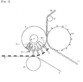
- FIG. 1 is a front view of the first Example of the device of the present invention.
- the present invention is described in the case of a pad of an adhesive bandage as an example of the article.
- a long tape 10 of composite material laminating Delnet (registered trademark) and a nonwoven fabric made of SBS-type block copolymer is used for the pad material tape.
- the width of the tape 10 is 35 mm and the thickness is 1 mm.
- the tape 10 is provided from above to the contact point, that is, to the cutting point, of cutting roll 1 and adhering roll 2.
- the radius of the cutting roll 1 is 300 mm
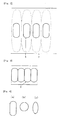
- each shape of the blade mold on the outer surface of the roll is identical to that of the pad 5 in Figure 2 and 140 molds are aligned on the outer surface.
- FIG. 3 An example of the alignment of the blade mold is shown in Figure 3.
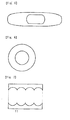
- the pad of Figure 3 has parallel linear parts of 20 mm length at the central part of the pad in longitudinal direction and half approximate oval shapes in the shape shown by the figure are attached to the linear parts respectively.
- a blade constructs a parallel linear part of adjacent pad in common, and two half approximate oval shape parts are attached to both sides thereof.
- An angle of the blade top is 30° to 90°, preferably 40° to 80°, and more preferably 50° to 70°. In case less than 30°, the blade becomes easy to wear and shortens the blade life. On the other hand in case exceeding 90°, it is necessary to increase load pressure to the adhering roll to cut and no sharp cutting surface may be formed. It is preferred to arrange the inside angle, that is to say, an angle formed by the pad material tape surface and the inside blade wall near to perpendicular.
- the pressing pressure of cutting roll against adhering roll is 1 to 3 kg/cm 2 . If the pressure is less than 1 kg/cm 2 , the blade sometimes will not cut out the pad accurately. If exceeding 3 kg/cm 2 , the blade will soon be worn and it hinders a long-time continuous operation.
- Figure 7 shows a shape of the pad material tape after pads are cut.
- the central area compartmentalized by the dotted lines at both upper and lower sides in the longitudinal direction is a hole formed by cutting out pads, and the rest areas partitioned by the both sides of the tape are remained waste parts of the long tape after cutting out pads, which continue for long distance as shown in 11 in Figure 1 and they are wound up and disposed of. Therefore no smaller waste of the tape material is formed.
- the radius of the adhering roll is 300 mm the same as that of the cutting roll. Consequently both rolls are synchronously driven at same rotation rate.
- the width of the anvil face is 1 mm and each anvil is arranged so as to correspond to each blade mold of the cutting roll. The position of the blade mold and anvil face always coincide with each other because both rolls are driven synchronously.
- Cylinder 4 shown in Figure 1 is arranged inside the cutting roll in the surface area surrounded by the anvil face. For the smooth adhesion of the pad without excessive stresses on the shaft, it is preferred to adjust the central axis of the cylinder in the longitudinal direction on the straight line passing through central line of the adhering roll rotation axis.
- Outer diameter of cylinder is 10 mm and piston connected to the shaft moves reciprocally in the cylinder.
- an air suction path is formed and connected to an air suction apparatus.
- the air suction path is connected to the pad suction mouth opened in central part of the shaft surface to hold a pad by suction.
- the shaft is hidden inside the cylinder by reducing air pressure in the piston room after adhering a pad.
- the bottom of the cylinder is connected to the air suction apparatus.
- the pad suction mouth for holding a pad is positioned at the same level as the anvil surface when the shaft is contained in the cylinder.
- the suction mouth is positioned in central area of the shaft face.
- the cylinder and shaft are constructed as shown in Figure 1 and the shaft is contained in the cylinder before the pad is cut. After the pad is cut, the air is sucked from the suction mouth of the shaft and the pad is held by suction on the shaft face.
- the shaft begins to protrude out of the adhering roll surface as the roll rotates.
- the suction from the suction mouth is stopped, concurrently the shaft begins to enter into the cylinder by reduced pressure, the shaft face returns to the level of the adhering roll surface and the pad cutting operation is ready.
- the adhesive tape 7 to which a pad is to be adhered is a long tape of a bandage base sheet on a side of which an adhesive is coated.
- the adhesive tape 7 is transferred by the adhesive tape transfer machine and a pad is attached thereto on the tape support roll 30 as shown in Figure 1.
- the article cutting and adhering device of the present invention may easily produce articles with a number of shapes other than conventional tetragons and the like and complete cutting and adhering of the articles to the adhesive surface of the bandage in one operation. Consequently the device of the present invention is in particular preferred to produce island pads and may easily set and alter spacing between adjacent pads on an adhesive tape by changing the ratio of the adhering roll rotation rate to the transfer rate of the adhesive tape transfer machine.
Landscapes
- Health & Medical Sciences (AREA)
- Engineering & Computer Science (AREA)
- General Health & Medical Sciences (AREA)
- Public Health (AREA)
- Heart & Thoracic Surgery (AREA)
- Vascular Medicine (AREA)
- Life Sciences & Earth Sciences (AREA)
- Animal Behavior & Ethology (AREA)
- Manufacturing & Machinery (AREA)
- Biomedical Technology (AREA)
- Veterinary Medicine (AREA)
- Absorbent Articles And Supports Therefor (AREA)
- Adhesive Tapes (AREA)
- Adhesive Tape Dispensing Devices (AREA)
- Auxiliary Devices For And Details Of Packaging Control (AREA)
- Collation Of Sheets And Webs (AREA)
- Folding Of Thin Sheet-Like Materials, Special Discharging Devices, And Others (AREA)
Applications Claiming Priority (2)
| Application Number | Priority Date | Filing Date | Title |
|---|---|---|---|
| JP2001303824A JP2003104620A (ja) | 2001-09-28 | 2001-09-28 | 長尺テープから物品を切出し粘着テープに貼付ける装置 |
| JP2001303824 | 2001-09-28 |
Publications (3)
| Publication Number | Publication Date |
|---|---|
| EP1297804A2 true EP1297804A2 (de) | 2003-04-02 |
| EP1297804A3 EP1297804A3 (de) | 2005-08-03 |
| EP1297804B1 EP1297804B1 (de) | 2007-06-06 |
Family
ID=19123849
Family Applications (1)
| Application Number | Title | Priority Date | Filing Date |
|---|---|---|---|
| EP02256744A Expired - Lifetime EP1297804B1 (de) | 2001-09-28 | 2002-09-27 | Vorrichtung zum Ausschneiden eines Artikels aus einem langen Band und zum Anhaften eines Artikels an einem Klebeband |
Country Status (6)
| Country | Link |
|---|---|
| US (1) | US6719031B2 (de) |
| EP (1) | EP1297804B1 (de) |
| JP (1) | JP2003104620A (de) |
| CN (1) | CN1303956C (de) |
| CA (1) | CA2405655A1 (de) |
| DE (1) | DE60220487T2 (de) |
Cited By (2)
| Publication number | Priority date | Publication date | Assignee | Title |
|---|---|---|---|---|
| DE10301837A1 (de) * | 2003-01-20 | 2004-07-29 | Beiersdorf Ag | Verfahren zur Herstellung von Pflastern |
| WO2010118096A1 (en) * | 2009-04-07 | 2010-10-14 | The Procter & Gamble Company | Apparatus and method for placing a desired length of tape material onto a moving web of material in a transverse orientation |
Families Citing this family (26)
| Publication number | Priority date | Publication date | Assignee | Title |
|---|---|---|---|---|
| DE10316235B3 (de) * | 2003-04-09 | 2004-09-16 | Siemens Ag | Einrichtung zum Ändern der Transportrichtung von flachen Sendungen und der Lage der Sendungen relativ zu ihrer Transportrichtung |
| US7306222B2 (en) * | 2003-05-14 | 2007-12-11 | Goss International Americas, Inc. | Sheet material feeder |
| US6848566B2 (en) * | 2003-06-30 | 2005-02-01 | The Procter & Gamble Company | Continuously adjustable apparatus for repositioning discrete articles |
| DE10361856A1 (de) * | 2003-12-30 | 2005-07-28 | Paul Hartmann Ag | Verfahren und Vorrichtung zum Applizieren eines Flachmaterialbahnabschnitts |
| WO2005075163A1 (ja) * | 2004-02-05 | 2005-08-18 | Zuiko Corporation | ウエブの加工装置および加工方法 |
| EP2100840A1 (de) * | 2008-03-12 | 2009-09-16 | Philip Morris Products S.A. | Patchapplikator-Vorrichtung und Verfahren |
| JP5572309B2 (ja) * | 2008-12-18 | 2014-08-13 | ユニ・チャーム株式会社 | 吸収性物品に係るシート状部材の複合体の製造方法及び製造装置 |
| WO2011086626A1 (ja) * | 2010-01-18 | 2011-07-21 | シャープ株式会社 | 粘着テープ貼付装置、及びそれを備えた液晶表示装置の製造装置、並びに粘着テープの貼付方法 |
| CN102824249A (zh) * | 2011-06-14 | 2012-12-19 | 上海智联精工机械有限公司 | 一种无纺布左右贴分切机构 |
| EP2626322A1 (de) | 2012-02-10 | 2013-08-14 | Nederlandse Organisatie voor toegepast -natuurwetenschappelijk onderzoek TNO | Folienverarbeitungsvorrichtung |
| CN104828324B (zh) * | 2015-05-11 | 2017-03-22 | 广东技术师范学院 | 一种普通胶带纸输送机构和输送方法 |
| CN105398757A (zh) * | 2015-12-16 | 2016-03-16 | 苏州太湖国家旅游度假区华刚金属制品厂 | 一种送料挂盘 |
| DE102016101985B4 (de) * | 2016-02-04 | 2018-06-21 | Khs Gmbh | Transportstern zum Führen von Behältern in einer Behälterbehandlungsanlage |
| ITUA20161815A1 (it) * | 2016-03-18 | 2017-09-18 | Gdm Spa | Unità di alimentazione di un componente di un articolo assorbente igienico provvista di un motore elettrico lineare. |
| CN107522001B (zh) * | 2016-06-20 | 2023-09-01 | 江阴市诚堡印刷包装机械有限公司 | 一种提手胶带用贴片复合机 |
| CN109110534B (zh) * | 2017-06-26 | 2020-02-28 | 东莞市雅康精密机械有限公司 | 贴胶装置 |
| DE102017118007A1 (de) * | 2017-08-08 | 2019-02-14 | Ditte Endriß | Abrollvorrichtung |
| CN109051974B (zh) * | 2018-07-05 | 2023-10-31 | 山东钢铁股份有限公司 | 一种随动式薄膜在线铺设切割装置 |
| CN108838023A (zh) * | 2018-09-18 | 2018-11-20 | 苏州市贝地龙新型材料有限公司 | 一种底板生产表面滚涂装置及其滚涂工艺 |
| CN109665367B (zh) * | 2018-12-14 | 2020-08-25 | 上海福赛特机器人有限公司 | 一种自动贴胶带的装置和方法 |
| MX2022012500A (es) * | 2020-04-06 | 2022-10-27 | Essity Hygiene & Health Ab | Un metodo para transferir uno o mas miembros de material no tejido recortados para uso en un articulo absorbente. |
| CN113855391B (zh) * | 2021-11-04 | 2023-01-10 | 河北广艺高新自动化科技有限公司 | 一种导管固定贴的生产工艺及生产设备 |
| CN113753654B (zh) * | 2021-11-11 | 2022-02-08 | 张家港马提亚科技有限公司 | 一种电子纸贴合设备 |
| DE102023111081A1 (de) * | 2023-04-28 | 2024-10-31 | Tesa Se | Applikationsvorrichtung für die Applikation von bahnförmigen Klebeelementen |
| CN116394628B (zh) * | 2023-05-09 | 2025-08-12 | 浙江慕伦纺织科技有限公司 | 一种防静电防火窗帘面料多层复合系统及方法 |
| CN118144406B (zh) * | 2024-05-10 | 2024-08-20 | 佛山市宾宏设备有限公司 | 一种自动焊接吸水垫的弹性绷带生产设备 |
Family Cites Families (10)
| Publication number | Priority date | Publication date | Assignee | Title |
|---|---|---|---|---|
| US3728191A (en) * | 1971-03-19 | 1973-04-17 | Kimberly Clark Co | Waistband tape application for disposable diapers |
| US3879246A (en) * | 1972-09-11 | 1975-04-22 | Robert J Walker | Laminating apparatus and method |
| US4664736A (en) * | 1983-01-24 | 1987-05-12 | Faasse Jr Adrain L | Pharmaceutical packaging method |
| US4767487A (en) * | 1985-10-18 | 1988-08-30 | Kimberly-Clark Corporation | Method for repositioning discrete articles |
| US4726876A (en) * | 1985-10-18 | 1988-02-23 | Kimberly-Clark Corporation | Apparatus for repositioning discrete articles |
| JPH07108305B2 (ja) * | 1987-10-09 | 1995-11-22 | 大正製薬株式会社 | 絆創膏の連続形成方法及びその装置 |
| DE3918470A1 (de) * | 1989-06-06 | 1990-12-13 | Joergen Gerhardt | Vorrichtung zum abfuehren von aus einem blattfoermigen material ausgestanzten materialbereichen |
| US5104116A (en) * | 1990-04-06 | 1992-04-14 | Kimberly-Clark Corporation | Applicator apparatus and process for rotating and placing a strip of material on a substrate |
| US6165306A (en) * | 1998-06-01 | 2000-12-26 | Kimberly-Clark Worldwide, Inc. | Process and apparatus for cutting of discrete components of a multi-component workpiece and depositing them with registration on a moving web of material |
| US6139004A (en) * | 1999-07-01 | 2000-10-31 | Kimberly-Clark Worldwide, Inc. | Assembly and method for rotating and placing strip of material on a substrate |
-
2001
- 2001-09-28 JP JP2001303824A patent/JP2003104620A/ja active Pending
-
2002
- 2002-09-24 US US10/253,253 patent/US6719031B2/en not_active Expired - Lifetime
- 2002-09-26 CN CNB021439451A patent/CN1303956C/zh not_active Expired - Fee Related
- 2002-09-27 EP EP02256744A patent/EP1297804B1/de not_active Expired - Lifetime
- 2002-09-27 CA CA002405655A patent/CA2405655A1/en not_active Abandoned
- 2002-09-27 DE DE60220487T patent/DE60220487T2/de not_active Expired - Fee Related
Cited By (4)
| Publication number | Priority date | Publication date | Assignee | Title |
|---|---|---|---|---|
| DE10301837A1 (de) * | 2003-01-20 | 2004-07-29 | Beiersdorf Ag | Verfahren zur Herstellung von Pflastern |
| WO2010118096A1 (en) * | 2009-04-07 | 2010-10-14 | The Procter & Gamble Company | Apparatus and method for placing a desired length of tape material onto a moving web of material in a transverse orientation |
| CN102378730A (zh) * | 2009-04-07 | 2012-03-14 | 宝洁公司 | 用于在横取向上将期望长度的带材放置到移动的纤维网材料上的装置和方法 |
| RU2509710C2 (ru) * | 2009-04-07 | 2014-03-20 | Дзе Проктер Энд Гэмбл Компани | Устройство и способ для укладки отрезка ленточного материала заданной длины на движущийся тонколистовой материал в поперечной ориентации |
Also Published As
| Publication number | Publication date |
|---|---|
| CA2405655A1 (en) | 2003-03-28 |
| CN1411791A (zh) | 2003-04-23 |
| DE60220487T2 (de) | 2008-02-07 |
| DE60220487D1 (de) | 2007-07-19 |
| US6719031B2 (en) | 2004-04-13 |
| EP1297804A3 (de) | 2005-08-03 |
| JP2003104620A (ja) | 2003-04-09 |
| US20030089210A1 (en) | 2003-05-15 |
| EP1297804B1 (de) | 2007-06-06 |
| CN1303956C (zh) | 2007-03-14 |
Similar Documents
| Publication | Publication Date | Title |
|---|---|---|
| US6719031B2 (en) | Device for cutting out an article from a long tape and adhering the article to an adhesive tape | |
| US11617687B2 (en) | Methods and apparatuses for assembling elastic laminates with different bond densities for absorbent articles | |
| EP1415628B1 (de) | Apparatur und Verfahren zur Herstellung eines Artikels | |
| EP1994919B1 (de) | Verfahren und Vorrichtung zur Anwendung einer geschachtelten ausschussfreien Öse auf eine laufende Bahn | |
| EP1295581B1 (de) | Verfahren und Vorrichtung zur Herstellung von Wegwerfkleidungsstücken | |
| US3728191A (en) | Waistband tape application for disposable diapers | |
| EP2374437B1 (de) | Verfahren und vorrichtung zur herstellung eines für saugfähige artikel adaptierten verbundelements aus blattähnlichen elementen | |
| US4364787A (en) | Apparatus for applying elastic ribbon segments to diapers | |
| US6820671B2 (en) | Apparatus and method for assembling absorbent garments | |
| US5562793A (en) | Methods and apparatus for making multi-layer absorbent products | |
| EP3092995B1 (de) | Ultraschallschweissvorrichtung und ultraschallschweissverfahren für bahnenförmiges element im zusammenhang mit saugfähigem artikel | |
| EP3092993B1 (de) | Ultraschallschweissvorrichtung und ultraschallschweissverfahren für bahnenförmige werkstücke in verbindung mit saugfähigen artikeln | |
| EP1864768B1 (de) | Schneidvorrichtung zur Herstellung von Hygieneprodukten und entsprechende Verwendung einer solchen Vorrichtung | |
| JP3681333B2 (ja) | 搬送物の搬送方法 | |
| JP5723859B2 (ja) | 吸収性物品に係る吸収体の製造装置、及び製造方法 | |
| KR102048717B1 (ko) | 휴대용 환부 보호용 드레싱 밴드 제조를 위한 원단 이송장치 | |
| JP5155809B2 (ja) | 複合シートの製造方法 | |
| RU2756266C2 (ru) | Абсорбирующие изделия для женской гигиены с прикрепляемыми боковыми створками и устройство для их производства |
Legal Events
| Date | Code | Title | Description |
|---|---|---|---|
| PUAI | Public reference made under article 153(3) epc to a published international application that has entered the european phase |
Free format text: ORIGINAL CODE: 0009012 |
|
| AK | Designated contracting states |
Kind code of ref document: A2 Designated state(s): AT BE BG CH CY CZ DE DK EE ES FI FR GB GR IE IT LI LU MC NL PT SE SK TR Designated state(s): AT BE BG CH CY CZ DE DK EE ES FI FR GB GR IE IT LI LU MC NL PT SE SK TR |
|
| AX | Request for extension of the european patent |
Extension state: AL LT LV MK RO SI |
|
| PUAL | Search report despatched |
Free format text: ORIGINAL CODE: 0009013 |
|
| AK | Designated contracting states |
Kind code of ref document: A3 Designated state(s): AT BE BG CH CY CZ DE DK EE ES FI FR GB GR IE IT LI LU MC NL PT SE SK TR |
|
| AX | Request for extension of the european patent |
Extension state: AL LT LV MK RO SI |
|
| 17P | Request for examination filed |
Effective date: 20060118 |
|
| AKX | Designation fees paid |
Designated state(s): DE FR GB IE |
|
| GRAP | Despatch of communication of intention to grant a patent |
Free format text: ORIGINAL CODE: EPIDOSNIGR1 |
|
| GRAS | Grant fee paid |
Free format text: ORIGINAL CODE: EPIDOSNIGR3 |
|
| GRAA | (expected) grant |
Free format text: ORIGINAL CODE: 0009210 |
|
| AK | Designated contracting states |
Kind code of ref document: B1 Designated state(s): DE FR GB IE |
|
| REG | Reference to a national code |
Ref country code: GB Ref legal event code: FG4D |
|
| REG | Reference to a national code |
Ref country code: IE Ref legal event code: FG4D |
|
| REF | Corresponds to: |
Ref document number: 60220487 Country of ref document: DE Date of ref document: 20070719 Kind code of ref document: P |
|
| PGFP | Annual fee paid to national office [announced via postgrant information from national office to epo] |
Ref country code: IE Payment date: 20070913 Year of fee payment: 6 |
|
| PGFP | Annual fee paid to national office [announced via postgrant information from national office to epo] |
Ref country code: DE Payment date: 20070920 Year of fee payment: 6 |
|
| ET | Fr: translation filed | ||
| PGFP | Annual fee paid to national office [announced via postgrant information from national office to epo] |
Ref country code: GB Payment date: 20070926 Year of fee payment: 6 |
|
| PLBE | No opposition filed within time limit |
Free format text: ORIGINAL CODE: 0009261 |
|
| STAA | Information on the status of an ep patent application or granted ep patent |
Free format text: STATUS: NO OPPOSITION FILED WITHIN TIME LIMIT |
|
| PGFP | Annual fee paid to national office [announced via postgrant information from national office to epo] |
Ref country code: FR Payment date: 20070914 Year of fee payment: 6 |
|
| 26N | No opposition filed |
Effective date: 20080307 |
|
| GBPC | Gb: european patent ceased through non-payment of renewal fee |
Effective date: 20080927 |
|
| REG | Reference to a national code |
Ref country code: FR Ref legal event code: ST Effective date: 20090529 |
|
| PG25 | Lapsed in a contracting state [announced via postgrant information from national office to epo] |
Ref country code: IE Free format text: LAPSE BECAUSE OF NON-PAYMENT OF DUE FEES Effective date: 20080929 |
|
| PG25 | Lapsed in a contracting state [announced via postgrant information from national office to epo] |
Ref country code: DE Free format text: LAPSE BECAUSE OF NON-PAYMENT OF DUE FEES Effective date: 20090401 |
|
| PG25 | Lapsed in a contracting state [announced via postgrant information from national office to epo] |
Ref country code: FR Free format text: LAPSE BECAUSE OF NON-PAYMENT OF DUE FEES Effective date: 20080930 |
|
| PG25 | Lapsed in a contracting state [announced via postgrant information from national office to epo] |
Ref country code: GB Free format text: LAPSE BECAUSE OF NON-PAYMENT OF DUE FEES Effective date: 20080927 |