EP1297225B1 - Strassenbaueinrichtung mit scharnierdeckel - Google Patents
Strassenbaueinrichtung mit scharnierdeckel Download PDFInfo
- Publication number
- EP1297225B1 EP1297225B1 EP20010947508 EP01947508A EP1297225B1 EP 1297225 B1 EP1297225 B1 EP 1297225B1 EP 20010947508 EP20010947508 EP 20010947508 EP 01947508 A EP01947508 A EP 01947508A EP 1297225 B1 EP1297225 B1 EP 1297225B1
- Authority
- EP
- European Patent Office
- Prior art keywords
- cover
- public
- frame
- finger
- road device
- Prior art date
- Legal status (The legal status is an assumption and is not a legal conclusion. Google has not performed a legal analysis and makes no representation as to the accuracy of the status listed.)
- Expired - Lifetime
Links
- 230000009975 flexible effect Effects 0.000 claims description 41
- 229910001141 Ductile iron Inorganic materials 0.000 claims description 3
- 230000005489 elastic deformation Effects 0.000 claims description 2
- 238000007373 indentation Methods 0.000 description 4
- 240000008042 Zea mays Species 0.000 description 2
- 238000006073 displacement reaction Methods 0.000 description 2
- 238000002513 implantation Methods 0.000 description 2
- 230000000284 resting effect Effects 0.000 description 2
- 238000013459 approach Methods 0.000 description 1
- 238000005452 bending Methods 0.000 description 1
- 230000010485 coping Effects 0.000 description 1
- 230000000694 effects Effects 0.000 description 1
- 239000000463 material Substances 0.000 description 1
- 238000000034 method Methods 0.000 description 1
- 230000035939 shock Effects 0.000 description 1
- XLYOFNOQVPJJNP-UHFFFAOYSA-N water Substances O XLYOFNOQVPJJNP-UHFFFAOYSA-N 0.000 description 1
Images


Classifications
-
- E—FIXED CONSTRUCTIONS
- E02—HYDRAULIC ENGINEERING; FOUNDATIONS; SOIL SHIFTING
- E02D—FOUNDATIONS; EXCAVATIONS; EMBANKMENTS; UNDERGROUND OR UNDERWATER STRUCTURES
- E02D29/00—Independent underground or underwater structures; Retaining walls
- E02D29/12—Manhole shafts; Other inspection or access chambers; Accessories therefor
- E02D29/14—Covers for manholes or the like; Frames for covers
- E02D29/1463—Hinged connection of cover to frame
-
- E—FIXED CONSTRUCTIONS
- E02—HYDRAULIC ENGINEERING; FOUNDATIONS; SOIL SHIFTING
- E02D—FOUNDATIONS; EXCAVATIONS; EMBANKMENTS; UNDERGROUND OR UNDERWATER STRUCTURES
- E02D29/00—Independent underground or underwater structures; Retaining walls
- E02D29/12—Manhole shafts; Other inspection or access chambers; Accessories therefor
- E02D29/14—Covers for manholes or the like; Frames for covers
- E02D29/1427—Locking devices
-
- Y—GENERAL TAGGING OF NEW TECHNOLOGICAL DEVELOPMENTS; GENERAL TAGGING OF CROSS-SECTIONAL TECHNOLOGIES SPANNING OVER SEVERAL SECTIONS OF THE IPC; TECHNICAL SUBJECTS COVERED BY FORMER USPC CROSS-REFERENCE ART COLLECTIONS [XRACs] AND DIGESTS
- Y10—TECHNICAL SUBJECTS COVERED BY FORMER USPC
- Y10T—TECHNICAL SUBJECTS COVERED BY FORMER US CLASSIFICATION
- Y10T137/00—Fluid handling
- Y10T137/6851—With casing, support, protector or static constructional installations
- Y10T137/6966—Static constructional installations
- Y10T137/6991—Ground supporting enclosure
- Y10T137/6995—Valve and meter wells
Definitions
- the invention relates to a road device with an articulated lid, in particular with lid formed in the form of a grid. It applies in particular the chimney coping devices of rainwater or closure devices for chimneys or chimneys inspecting an underground water system, such as manholes or sidewalk.
- a device for crowning chimneys access or evacuation comprising a frame and a lid constituted by a removable grid adapted to be articulated to the frame about an axis extending in the vicinity of one side of the gate, this gate being constituted, in the direction of its pivot axis, a middle part and two side parts with protruding trunnions in frame housing elastically connected to the middle part, which gives it a structure globally deformable.
- the deformability of the frame of the grid is put to advantage by giving it also one or more bars also deformable resiliently adapted to come in snap engagement with snap lugs worn by the frame to prevent opening purely manual look allowing removal of the grid.
- the shrinkage of it is possible by pinching the outermost side bars in order to release its trunnions from their housing of the frame, by means of levers of fortune.
- the object of the invention is to remedy these drawbacks and concerns for this purpose a road device consisting of a hinged rigid cover on a frame, the cover comprising two lateral edges carrying two trunnions defining an axis of articulation parallel to a hinge line lid and coming into two corresponding cells of the chassis at least partially supported by a wall of the chassis, characterized in that the lid further comprises an elastically flexible finger extending parallel to the side edges, the free end of this finger being located near the hinge edge and being adapted for cooperate with a thrust pin carried by the corresponding hinge edge of the chassis so as to allow, by elastic deformation of the finger resting against the pin, the establishment of the pins in their cells and their withdrawal from them.
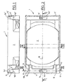
- the road device illustrated by the figures is a crowning device for sewerage network, intended to be sealed in the ground, for example in a pavement, at the top end an evacuation or access chimney (not shown); this device is here a quadrilateral but this form is not naturally limiting.
- the device consists of two pieces of ductile iron, namely a frame 1 here of rectangular general shape delimiting an access 2, here circular, at the chimney, and a rigid grid 3 forming a shutter cover of the chassis.
- the cover 3 and the frame 1 are articulated to one another by means of means of mutual articulation, so that the lid can be moved between a closed position where it rests on the frame and covers approximately access and an open position where he releases it substantially, more precisely in an approximately pivotal movement around an approximately horizontal axis parallel to the small sides of the rectangle of the device resting in the chassis between the two positions mentioned above.
- the word “horizontal (e)” means (and will mean throughout the text) "Parallel to the plane in which the chassis extends", although this plan may be inclined if the device is intended to be implanted at the surface of an inclined floor, and the word “vertical (e)” will mean "perpendicular to the plane in which the chassis extends.
- the means of mutual articulation of the cover 3 and the chassis 1 are respectively two journals 30A, 30B laterally projecting respectively on both sides of the lid, carried by the two lateral edges near an end bank 31 called in the suite "shore of the latter, these two journals being aligned axially one with each other to define the approximately horizontal pivot axis of the cover, and two cells 10 of the chassis adapted to receive respectively these two trunnions of the lid.
- the cells 10 of the chassis are bordered by an end edge 11 and side edges 12 of the frame that belong to the outer wall of it, the end edge 11 being intended to receive facing the shore articulation 31 of the cover near which are placed the trunnions 30A, 30B; this end edge 11 of the frame serves as a stop on the lid 3 to define an open position abutting thereof.
- the two cells 10 are overhung by a wall 13 whose upper face is coplanar with the upper face of the frame, that is to say the upper edge of the outer wall of the latter, and approximately with the upper face of the lid 3 when it is in position closure; for one of the cells, the overhanging wall 13 presents a notch 130 whose function will be mentioned later, while for the other cell, the wall 13 connects without discontinuity to the end edge 11 of the chassis and therefore constitutes a bridge of material above it.
- each lug comprises, at its upper part, inclined lateral surfaces converging on one towards the other in the direction of its upper face, the lateral surface 141, 141 'of each lug located on the side of the large median 15 being intended to constitute a thrust surface acting on a flexible member of the lid as will be seen later; at their lower part, the two pins also have inclined lateral surfaces, and more particularly a lateral surface 142, 142 'situated on the side of the high median of the chassis and deviating from this great median by going to the underside ergot
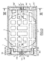
- the grid constituting the lid 3 is formed in one piece, generally rectangular shape, of longitudinal bars extending perpendicular to its axis of articulation and bars cross-sections extending parallel to the axis, these bars delimiting windows through and through the thickness of the lid so that it is light while having a rigid frame.
- the regions of longitudinal bars 32A, 32B entering the forming the lateral edges of the grid 3 which carry the journals 30A, 30B have an inverted L-shaped section whose horizontal branch extends to the top of the grid and whose free end of the branch vertical is at the bottom of the grid; horizontal branches Ls returned from these two bars 32A, 32B extend in the same sense, and so the vertical branch of the L returned from one of the bars 32A defines a side edge of the grid, while the opposite side edge is defined by the free end of the horizontal branch of the L returned from the other bar 32B whose vertical branch is set back from this song lateral; as the two trunnions 30A, 30B extend out of the contour of the grid on approximately the same length, the 30A pin carried by the first bar 32A is shorter than the trunnion 30B carried by the second bar 32B (see Figures 7 and 8); to facilitate its implementation, the shorter trunnion 30A is further chamfered or truncated so as to present a region further shortened on
- the end bank 31 of the grid near which are placed the journals 30A, 30B consists of aligned sections, here two sections 31A, 31B extending longitudinally to form this edge, separated by a space 33 extending over a distance approximately equal on both sides of the median 15 of the chassis 1 when the grid 3 is inserted in the closed position.
- This space 33 is extended by an indentation 34 extending towards the central region of the grid, whose bottom is constituted by a parallel transverse bar at the hinge bank 31; this notch 34, wider than the space 33 extends on both sides of the large median 15.
- the transverse bar 35 belonging to the rigid frame carries, in one piece with it, an elastically flexible finger 36 extending into the notch approximately along the large median 15 of the chassis when the grid is in the closed position, that is to say perpendicularly to the hinge pin approximately from the middle of the crossbar 35, into the space 33 between the two sections 31A, 31B, from a distance of these, the region of the free end of the flexible finger 36 being approximately equidistant from these two sections.
- the surface of the free end region of the coplanar finger with the upper face of the grid has a large opening 361 opening in this upper face as well as on the side of the near section 31B the longest 30B journal;
- this recess 361 constitutes a housing for the lateral region of the lug 14 of the frame situated on the side of the large median 15, when the grid is in the closed position in the chassis;
- the lateral surface of the same region of the finger 36 extending below the level of the recess 361 defines an inverted V-shaped ridge pointing in opposite of section 31B, consisting of an upper inclined surface 365 and a lower surface 362 overhanging.
- a substantially vertical face 363 connects the inclined surface 365 to the upper face of the grid.
- the end edge 31 'of the opposite and approximately parallel grid at the hinge bank 31, is also constituted of sections, here of three sections 31A ', 31B', 31C 'extending longitudinally to form this bank of which two sections 31A ', 31B' are separated by a space 33 ' extending about an equal distance on either side of the large median 15 of the frame when the grid 3 is inserted in position of closing.
- This space 33 ' is also extended by an indentation 34' extending towards the central region of the grid, the bottom of which is constituted by a transverse bar 35 'parallel to the end edge 31'; this notch 34 ', wider than the space 33', extends on both sides of the great median 15.
- the transverse bar 35 'of the rigid frame carries, in a single piece with him, a finger 36 'locking the lid in the closed position, also elastically flexible, extending into the notch approximately along the big median 15 of the chassis when the grid is in the closed position, that is to say perpendicular to the axis articulation approximately from the middle of the transverse bar 35 ', in the space 33 'between the two sections 31A', 31B ', at a distance of these, the free end region of the flexible finger 36 'being approximately equidistant from these two sections.
- the surface of the free end region of the finger 36 'coplanar with the upper face of the grid has a recess 361 'opening in this upper face and on the side of the section 31B 'which is itself on the side of the longer trunnion 30B; this recess 361 'constitutes a housing for the lateral region of the lug 14 'of the chassis located on the side of the large median 15, when the gate is in the closed position in the frame ;
- the free end of the flexible finger 36 passes under the thrust pin 14 and the inclined surface 365 of the finger approaches the inclined lateral surface 142 of the lug 14 from below to constrain the flexible finger 36 whose second function is to maintain the bank articulation 31 of the grid in contact with the frame 1.
- the inclination the surface 365 corresponds to that of the surface 142.
- the second finger flexible 36 ' located opposite the articulation and adapted to cooperate by snapping with the second thrust pin 14 'of the chassis.
- the push pin 14 ' has a shape as seen inverted V-shaped convex with a surface forming an upper ramp 141 ' turned upward and a lower ramp surface 142 'overhanging.
- the surface 141 ' is less inclined on the vertical than the surface 142 ', typical inclination values being of the order of 20 ° and 30 ° respectively.
- a tool for example a crowbar between the grill and the frame in a remote area of the articulation, in particular at the level of the end rim 31 'or at the level lateral edges 12 near the shore 31 '; then, taking support against the chassis, a tilting effort is made in the direction of the opening.
- the flexible finger 36 'thus ensures locking and unlocking grid 3, without the need to act directly on this one, which could damage it.
- the surface 362 of the finger 36 therefore plays no part active role, and that the surface 142 of the thrust pin 14 does not intervene when assembly or disassembly of the grid; on the other hand, this surface allows, in cooperation with the inclined surface 366 of the finger 36, to grid on the frame in the closed position of the grid.
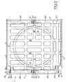
- FIG. 12 shows an alternative embodiment of a road device according to the invention, in which the device has a general shape approximately square.
- the general form is square and not rectangular, and in that the grid 3 has a geometry only slightly different as a result of this square shape, the device of Figure 12 will not be described in detail; the visible elements on FIG. 12 which have already been described with reference to FIGS. the same numerical references.
- the invention is not limited to these forms realization, and we can foresee others without leaving its framework; we may in particular provide embodiments in which the lid is not in the form of a grid, and forms in which it exists along the same edge of the lid several spaces extended by an indentation in which extends an elastically flexible finger.
- the lid is a tampon and has at least one flexible finger on the underside, that is to say, extending under its lower face, cooperating with at least one the lug of the frame shifted downward relative to the embodiments which have been described above.
Landscapes
- Engineering & Computer Science (AREA)
- Civil Engineering (AREA)
- Life Sciences & Earth Sciences (AREA)
- General Life Sciences & Earth Sciences (AREA)
- Mining & Mineral Resources (AREA)
- Paleontology (AREA)
- General Engineering & Computer Science (AREA)
- Structural Engineering (AREA)
- Environmental & Geological Engineering (AREA)
- Sewage (AREA)
- Underground Structures, Protecting, Testing And Restoring Foundations (AREA)
- Refuge Islands, Traffic Blockers, Or Guard Fence (AREA)
- Emergency Lowering Means (AREA)
- Pivots And Pivotal Connections (AREA)
- Bridges Or Land Bridges (AREA)
- Connector Housings Or Holding Contact Members (AREA)
- Road Signs Or Road Markings (AREA)
- Carriages For Children, Sleds, And Other Hand-Operated Vehicles (AREA)
- Refuse Receptacles (AREA)
- Road Paving Structures (AREA)
Claims (10)
- Straßenbauvorrichtung, die aus einem steifen Deckel (3) besteht, der gelenkig auf einem Rahmen (1) befestigt ist, wobei der Deckel (3) zwei Seitenränder (32A, 32B) aufweist, die zwei Zapfen (30A, 30B) tragen, welche eine Gelenkachse parallel zu einer Gelenkleiste (31) des Deckels definieren und sich in zwei entsprechende Vertiefungen (10) des Rahmens einfügen, die zumindest zum Teil von einer Wand (13) des Rahmens überlagert werden, dadurch gekennzeichnet, dass der Deckel (3) außerdem einen elastisch biegsamen Finger (36) aufweist, der sich parallel zu den Seitenrändern (32A, 32B) erstreckt, wobei das freie Ende dieses Fingers (36) sich in der Nähe der Gelenkleiste (31) befindet und ausgelegt ist, um mit einer Schubnase (14) zusammenzuwirken, die auf dem entsprechenden Gelenkrand (11) des Rahmens sitzt, um durch elastische Verformung des Fingers (36) in Anlage gegen die Nase (14) das Einsetzen der Zapfen (30A, 30B) in ihre jeweiligen Vertiefungen (10) und ihr Zurückziehen aus diesen zu ermöglichen.
- Straßenbauvorrichtung nach Anspruch 1, dadurch gekennzeichnet, dass die Schubnase (14) eine obere Seitenfläche (141), die schräg nach oben zeigt, und eine überstehende untere Seitenfläche (142) aufweist, die in der Schließstellung des Deckels (3) auf dem Rahmen (1) mit einer entsprechenden Schrägfläche (365) zusammenwirkt, die vom freien Ende des elastisch biegsamen Fingers (36) getragen wird.
- Straßenbauvorrichtung nach einem der Ansprüche 1 und 2, dadurch gekennzeichnet, dass der Rahmen (1) gegenüber der Nase (14) eine zweite Schubnase (14') aufweist, die von einer Endleiste (31') getragen wird, die der Gelenkleiste (31) gegenüberliegt und ausgelegt ist, um durch Einklinken mit dem freien Ende eines zweiten elastisch biegsamen Fingers (36') zusammenzuwirken, der vom Deckel (3) getragen wird.
- Straßenbauvorrichtung nach Anspruch 3, dadurch gekennzeichnet, dass die zweite Schubnase (14') und das freie Ende des zweiten elastisch biegsamen Fingers (36') zusammenwirkende Flächen (141', 142', 365', 362') aufweisen, die Nocken bilden, welche in Öffnungs- und/oder Schließrichtung des Deckels aktiv sind.
- Straßenbauvorrichtung nach einem der Ansprüche 3 und 4, dadurch gekennzeichnet, dass das freie Ende jedes elastisch biegsamen Fingers (36, 36') eine Vertiefung (361, 361') für einen Seitenbereich der Nase (14, 14') aufweist.
- Straßenbauvorrichtung nach einem der Ansprüche 3 bis 5, dadurch gekennzeichnet, dass die elastisch biegsamen Finger (36, 36') senkrecht zu der Richtung verlaufen, in der sich die Gelenkzapfen (30A, 30B) erstrecken.
- Straßenbauvorrichtung nach einem der Ansprüche 3 bis 6, dadurch gekennzeichnet, dass die elastisch biegsamen Finger (36, 36') sich in jeweiligen Aussparungen (34, 34') des Deckels (3) erstrecken, wobei das freie Ende jedes Fingers in einem Raum (33, 33') mündet, der in der entsprechenden Leiste (31, 31') des Deckels ausgebildet ist.
- Straßenbauvorrichtung nach einem der Ansprüche 1 bis 7, dadurch gekennzeichnet, dass der Deckel (3) ein Rost ist.
- Straßenbauvorrichtung nach einem der Ansprüche 1 bis 8, dadurch gekennzeichnet, dass der Deckel (3) aus Gusseisen ist.
- Straßenbauvorrichtung nach einem der Ansprüche 1 bis 9, dadurch gekennzeichnet, dass der Deckel (3) die allgemeine Form eines Vierecks hat.
Priority Applications (2)
| Application Number | Priority Date | Filing Date | Title |
|---|---|---|---|
| DK01947508T DK1297225T3 (da) | 2001-06-18 | 2001-06-18 | Vejindretning med hængslet dæksel |
| SI200130269T SI1297225T1 (en) | 2000-07-06 | 2001-06-18 | Road network device with articulated cover |
Applications Claiming Priority (3)
| Application Number | Priority Date | Filing Date | Title |
|---|---|---|---|
| FR0008834 | 2000-07-06 | ||
| FR0008834A FR2811346B1 (fr) | 2000-07-06 | 2000-07-06 | Dispositif de voirie a couvercle articule tel que les dispositifs de couronnement ou de fermeture des cheminees de sol |
| PCT/FR2001/001890 WO2002002878A1 (fr) | 2000-07-06 | 2001-06-18 | Dispositif de voirie a couvercle articule |
Publications (2)
| Publication Number | Publication Date |
|---|---|
| EP1297225A1 EP1297225A1 (de) | 2003-04-02 |
| EP1297225B1 true EP1297225B1 (de) | 2004-10-27 |
Family
ID=8852200
Family Applications (1)
| Application Number | Title | Priority Date | Filing Date |
|---|---|---|---|
| EP20010947508 Expired - Lifetime EP1297225B1 (de) | 2000-07-06 | 2001-06-18 | Strassenbaueinrichtung mit scharnierdeckel |
Country Status (21)
| Country | Link |
|---|---|
| US (1) | US6722813B2 (de) |
| EP (1) | EP1297225B1 (de) |
| AR (1) | AR031376A1 (de) |
| AT (1) | ATE280864T1 (de) |
| AU (1) | AU2001269177A1 (de) |
| BR (1) | BR0106938B1 (de) |
| CA (1) | CA2382704C (de) |
| CZ (1) | CZ298886B6 (de) |
| DE (1) | DE60106762T2 (de) |
| ES (1) | ES2230334T3 (de) |
| FR (1) | FR2811346B1 (de) |
| HR (1) | HRP20020202B1 (de) |
| HU (1) | HU226364B1 (de) |
| MY (1) | MY127418A (de) |
| NO (1) | NO20021087L (de) |
| PL (1) | PL208965B1 (de) |
| PT (1) | PT1297225E (de) |
| RS (1) | RS49950B (de) |
| SK (1) | SK286522B6 (de) |
| WO (1) | WO2002002878A1 (de) |
| ZA (1) | ZA200201340B (de) |
Families Citing this family (7)
| Publication number | Priority date | Publication date | Assignee | Title |
|---|---|---|---|---|
| GB2390629B (en) * | 2002-07-10 | 2005-12-21 | Saint Gobain Pipelines Plc | A frame for bounding a recess and related assemblies |
| US7293937B2 (en) * | 2003-03-25 | 2007-11-13 | Aco Severin Ahlmann Gmbh & Co. Kg | Cover arrangement |
| MX2009002116A (es) * | 2006-08-25 | 2009-05-12 | Gmi Composites Inc | Montaje de tapa de registro compuesto y reforzado, y componentes del mismo. |
| US20120177440A1 (en) * | 2011-01-10 | 2012-07-12 | Consolidated Edison Company Of New York, Inc. | Manhole safety gratings |
| CA2837496C (en) * | 2012-12-18 | 2016-12-13 | Canada Pipe Company ULC | Locking mechanism for a cover |
| WO2016133417A1 (en) | 2015-02-18 | 2016-08-25 | Majkić Doo Preduzeće Za Proizvodnju, Trgovinu I Usluge | Mechanism for prevention of theft of manhole covers |
| AU2021104670B4 (en) | 2021-06-30 | 2021-12-09 | Stormtech Pty Limited | Grating and method of manufacturing a grating |
Family Cites Families (12)
| Publication number | Priority date | Publication date | Assignee | Title |
|---|---|---|---|---|
| US2257791A (en) * | 1941-10-07 | iinltfft staffs patf nt | ||
| ES2028773T3 (es) * | 1987-04-07 | 1992-10-16 | Pont-A-Mousson S.A. | Registro de calzada de bisagra en t. |
| CH677244A5 (de) * | 1988-07-05 | 1991-04-30 | Von Roll Ag | |
| US4892221A (en) * | 1988-12-06 | 1990-01-09 | Menasha Corporation | Detachable lid container |
| CH678639A5 (de) * | 1989-07-11 | 1991-10-15 | Von Roll Ag | |
| FR2652598B1 (fr) * | 1989-09-29 | 1991-12-13 | Pont A Mousson | Regard de chaussee a charniere verrouille. |
| FR2674550B1 (fr) * | 1991-03-27 | 1993-05-21 | Pont A Mousson | Moyens pour assujettir une piece de recouvrement a un cadre de piece de voirie. |
| FR2674560B1 (fr) * | 1991-03-28 | 1993-06-11 | Pont A Mousson | Dispositif de couronnement d'une cheminee d'acces ou d'evacuation. |
| FR2681356B1 (fr) * | 1991-09-16 | 1997-04-04 | Pont A Mousson | Regard de chaussee a tampon verrouille. |
| US5324135A (en) * | 1993-04-28 | 1994-06-28 | Dennis Smith | Locking cover |
| US5628152A (en) * | 1995-08-16 | 1997-05-13 | Bowman; Harold M. | Adjustable manhole cover support with shield |
| FR2780997A1 (fr) * | 1998-07-13 | 2000-01-14 | Manoir Ind | Regard de chaussee a couvercle flottant |
-
2000
- 2000-07-06 FR FR0008834A patent/FR2811346B1/fr not_active Expired - Fee Related
-
2001
- 2001-06-06 AR ARP010102694 patent/AR031376A1/es active IP Right Grant
- 2001-06-18 SK SK457-2002A patent/SK286522B6/sk not_active IP Right Cessation
- 2001-06-18 ES ES01947508T patent/ES2230334T3/es not_active Expired - Lifetime
- 2001-06-18 US US10/070,163 patent/US6722813B2/en not_active Expired - Lifetime
- 2001-06-18 AU AU2001269177A patent/AU2001269177A1/en not_active Abandoned
- 2001-06-18 AT AT01947508T patent/ATE280864T1/de active
- 2001-06-18 PL PL352799A patent/PL208965B1/pl unknown
- 2001-06-18 BR BRPI0106938-1A patent/BR0106938B1/pt not_active IP Right Cessation
- 2001-06-18 DE DE2001606762 patent/DE60106762T2/de not_active Expired - Lifetime
- 2001-06-18 CA CA002382704A patent/CA2382704C/fr not_active Expired - Fee Related
- 2001-06-18 HU HU0204406A patent/HU226364B1/hu not_active IP Right Cessation
- 2001-06-18 WO PCT/FR2001/001890 patent/WO2002002878A1/fr not_active Ceased
- 2001-06-18 RS YUP15802 patent/RS49950B/sr unknown
- 2001-06-18 EP EP20010947508 patent/EP1297225B1/de not_active Expired - Lifetime
- 2001-06-18 PT PT01947508T patent/PT1297225E/pt unknown
- 2001-06-18 HR HR20020202A patent/HRP20020202B1/xx not_active IP Right Cessation
- 2001-06-18 CZ CZ20021321A patent/CZ298886B6/cs not_active IP Right Cessation
- 2001-07-03 MY MYPI20013166 patent/MY127418A/en unknown
-
2002
- 2002-02-18 ZA ZA200201340A patent/ZA200201340B/xx unknown
- 2002-03-05 NO NO20021087A patent/NO20021087L/no not_active Application Discontinuation
Also Published As
| Publication number | Publication date |
|---|---|
| HU226364B1 (en) | 2008-09-29 |
| HRP20020202A2 (en) | 2003-06-30 |
| MY127418A (en) | 2006-11-30 |
| ZA200201340B (en) | 2002-09-02 |
| CA2382704C (fr) | 2006-08-08 |
| ATE280864T1 (de) | 2004-11-15 |
| DE60106762D1 (de) | 2004-12-02 |
| SK4572002A3 (en) | 2002-10-08 |
| BR0106938A (pt) | 2002-05-14 |
| SK286522B6 (sk) | 2008-12-05 |
| PT1297225E (pt) | 2005-02-28 |
| NO20021087L (no) | 2002-05-06 |
| CA2382704A1 (fr) | 2002-01-10 |
| HUP0204406A2 (en) | 2003-03-28 |
| EP1297225A1 (de) | 2003-04-02 |
| BR0106938B1 (pt) | 2009-05-05 |
| RS49950B (sr) | 2008-09-29 |
| DE60106762T2 (de) | 2005-11-03 |
| WO2002002878A1 (fr) | 2002-01-10 |
| YU15802A (sh) | 2004-03-12 |
| CZ298886B6 (cs) | 2008-03-05 |
| HRP20020202B1 (en) | 2005-04-30 |
| FR2811346B1 (fr) | 2002-08-23 |
| PL208965B1 (pl) | 2011-06-30 |
| US20020141820A1 (en) | 2002-10-03 |
| AR031376A1 (es) | 2003-09-24 |
| AU2001269177A1 (en) | 2002-01-14 |
| US6722813B2 (en) | 2004-04-20 |
| PL352799A1 (en) | 2003-09-08 |
| NO20021087D0 (no) | 2002-03-05 |
| ES2230334T3 (es) | 2005-05-01 |
| FR2811346A1 (fr) | 2002-01-11 |
Similar Documents
| Publication | Publication Date | Title |
|---|---|---|
| EP1525354B1 (de) | Gitter zum verschliessen einer rinne oder ähnlichem | |
| CA2577042C (fr) | Dispositif permettant d'obturer un cadre, comprenant un panneau monte articule amovible sur le cadre | |
| EP1297225B1 (de) | Strassenbaueinrichtung mit scharnierdeckel | |
| EP2543800B1 (de) | Verriegelungs- und Entriegelungsvorrichtung mindestens eines Abdeckelements auf einem Gestellrahmen dieses Elements | |
| EP1160382B1 (de) | Einstiegschacht mit angelenktem Deckel und Diebstahlsicherungsvorrichtung für eine Ausschachtung im Boden | |
| EP1091046B1 (de) | Verschlussvorrichtung für einen Kontroll- oder Inspektionsschacht | |
| EP0724052B1 (de) | Türgriff eines Kraftfahrzeugs zur schnellen Montage durch ein Keil-Nockensystem | |
| EP0796949B1 (de) | Mit Scharnier versehene Verkehrswege-Vorrichtung mit einer Abdeckung von der Art eines Rostes oder Kanaldeckels und mit einem Stützrahmen | |
| EP2167736B1 (de) | Strassenvorrichtung mit stützrahmen und einem drehbar am rahmen montiertem abdeckelement nach art einer schachtabdeckung oder eines deckels | |
| EP3115515B1 (de) | Schachtabdeckung mit einem rahmen und einem paneel | |
| EP1936040B1 (de) | Straßenreinigungsvorrichtung | |
| WO2018104637A1 (fr) | Dispositif de recouvrement d'un caniveau | |
| EP1553233B1 (de) | Bodenablauf | |
| EP0771718A1 (de) | Fahrzeugaufbau, bestehend aus einem Unterbau, einem Oberbau und mindestens einer Schiebetür und zwei Flügeltüren | |
| EP1067242B1 (de) | Grubenabdeckung | |
| FR2731022A1 (fr) | Caniveau en beton | |
| EP0510288A1 (de) | Halter für Plomben zur Befestigung an den beiden Flügeln einer Tür, insbesondere eines Behälters | |
| WO2025224028A1 (fr) | Dispositif de couverture pour caniveau | |
| WO2011070263A1 (fr) | Ensemble a cadre et tampon de fermeture du cadre notamment pour regard de chaussee | |
| EP1375082A1 (de) | Einheit zum Lagern für eine öffentlich zugängliche Arbeitsstelle | |
| EP1191153A1 (de) | Schachtabdeckung mit Scharnier | |
| FR2731023A1 (fr) | Dispositif de voirie a charniere comprenant un couvercle du type grille ou tampon et un cadre support | |
| FR2576353A1 (fr) | Dispositif de blocage de volets de protection pour ouvertures dans les murs |
Legal Events
| Date | Code | Title | Description |
|---|---|---|---|
| PUAI | Public reference made under article 153(3) epc to a published international application that has entered the european phase |
Free format text: ORIGINAL CODE: 0009012 |
|
| 17P | Request for examination filed |
Effective date: 20020309 |
|
| AK | Designated contracting states |
Kind code of ref document: A1 Designated state(s): AT BE CH CY DE DK ES FI FR GB GR IE IT LI LU MC NL PT SE TR |
|
| AX | Request for extension of the european patent |
Extension state: AL LT LV MK RO SI |
|
| GRAP | Despatch of communication of intention to grant a patent |
Free format text: ORIGINAL CODE: EPIDOSNIGR1 |
|
| GRAS | Grant fee paid |
Free format text: ORIGINAL CODE: EPIDOSNIGR3 |
|
| GRAA | (expected) grant |
Free format text: ORIGINAL CODE: 0009210 |
|
| AK | Designated contracting states |
Kind code of ref document: B1 Designated state(s): AT BE CH CY DE DK ES FI FR GB GR IE IT LI LU MC NL PT SE TR |
|
| AX | Request for extension of the european patent |
Extension state: RO SI |
|
| REG | Reference to a national code |
Ref country code: GB Ref legal event code: FG4D Free format text: NOT ENGLISH |
|
| REG | Reference to a national code |
Ref country code: CH Ref legal event code: NV Representative=s name: KIRKER & CIE SA Ref country code: CH Ref legal event code: EP |
|
| GBT | Gb: translation of ep patent filed (gb section 77(6)(a)/1977) |
Effective date: 20041027 |
|
| REG | Reference to a national code |
Ref country code: IE Ref legal event code: FG4D Free format text: FRENCH |
|
| REF | Corresponds to: |
Ref document number: 60106762 Country of ref document: DE Date of ref document: 20041202 Kind code of ref document: P |
|
| REG | Reference to a national code |
Ref country code: SE Ref legal event code: TRGR |
|
| REG | Reference to a national code |
Ref country code: GR Ref legal event code: EP Ref document number: 20050400206 Country of ref document: GR |
|
| REG | Reference to a national code |
Ref country code: PT Ref legal event code: SC4A Free format text: AVAILABILITY OF NATIONAL TRANSLATION Effective date: 20041229 |
|
| REG | Reference to a national code |
Ref country code: DK Ref legal event code: T3 |
|
| LTIE | Lt: invalidation of european patent or patent extension |
Effective date: 20041027 |
|
| REG | Reference to a national code |
Ref country code: ES Ref legal event code: FG2A Ref document number: 2230334 Country of ref document: ES Kind code of ref document: T3 |
|
| PG25 | Lapsed in a contracting state [announced via postgrant information from national office to epo] |
Ref country code: CY Free format text: LAPSE BECAUSE OF FAILURE TO SUBMIT A TRANSLATION OF THE DESCRIPTION OR TO PAY THE FEE WITHIN THE PRESCRIBED TIME-LIMIT Effective date: 20050618 |
|
| PG25 | Lapsed in a contracting state [announced via postgrant information from national office to epo] |
Ref country code: MC Free format text: LAPSE BECAUSE OF NON-PAYMENT OF DUE FEES Effective date: 20050630 |
|
| PLBE | No opposition filed within time limit |
Free format text: ORIGINAL CODE: 0009261 |
|
| STAA | Information on the status of an ep patent application or granted ep patent |
Free format text: STATUS: NO OPPOSITION FILED WITHIN TIME LIMIT |
|
| 26N | No opposition filed |
Effective date: 20050728 |
|
| PGFP | Annual fee paid to national office [announced via postgrant information from national office to epo] |
Ref country code: DK Payment date: 20130611 Year of fee payment: 13 Ref country code: SE Payment date: 20130612 Year of fee payment: 13 |
|
| PGFP | Annual fee paid to national office [announced via postgrant information from national office to epo] |
Ref country code: GR Payment date: 20130514 Year of fee payment: 13 Ref country code: FI Payment date: 20130611 Year of fee payment: 13 |
|
| PGFP | Annual fee paid to national office [announced via postgrant information from national office to epo] |
Ref country code: BE Payment date: 20130614 Year of fee payment: 13 |
|
| REG | Reference to a national code |
Ref country code: DK Ref legal event code: EBP Effective date: 20140630 |
|
| PG25 | Lapsed in a contracting state [announced via postgrant information from national office to epo] |
Ref country code: SE Free format text: LAPSE BECAUSE OF NON-PAYMENT OF DUE FEES Effective date: 20140619 Ref country code: FI Free format text: LAPSE BECAUSE OF NON-PAYMENT OF DUE FEES Effective date: 20140618 |
|
| REG | Reference to a national code |
Ref country code: SE Ref legal event code: EUG |
|
| REG | Reference to a national code |
Ref country code: GR Ref legal event code: ML Ref document number: 20050400206 Country of ref document: GR Effective date: 20150105 |
|
| PG25 | Lapsed in a contracting state [announced via postgrant information from national office to epo] |
Ref country code: GR Free format text: LAPSE BECAUSE OF NON-PAYMENT OF DUE FEES Effective date: 20150105 |
|
| PG25 | Lapsed in a contracting state [announced via postgrant information from national office to epo] |
Ref country code: DK Free format text: LAPSE BECAUSE OF NON-PAYMENT OF DUE FEES Effective date: 20140630 |
|
| REG | Reference to a national code |
Ref country code: FR Ref legal event code: PLFP Year of fee payment: 16 |
|
| PGFP | Annual fee paid to national office [announced via postgrant information from national office to epo] |
Ref country code: LU Payment date: 20160610 Year of fee payment: 16 Ref country code: IE Payment date: 20160609 Year of fee payment: 16 |
|
| PGFP | Annual fee paid to national office [announced via postgrant information from national office to epo] |
Ref country code: NL Payment date: 20160610 Year of fee payment: 16 |
|
| REG | Reference to a national code |
Ref country code: FR Ref legal event code: PLFP Year of fee payment: 17 |
|
| PG25 | Lapsed in a contracting state [announced via postgrant information from national office to epo] |
Ref country code: BE Free format text: LAPSE BECAUSE OF NON-PAYMENT OF DUE FEES Effective date: 20140630 |
|
| PGFP | Annual fee paid to national office [announced via postgrant information from national office to epo] |
Ref country code: FR Payment date: 20170511 Year of fee payment: 17 Ref country code: CH Payment date: 20170613 Year of fee payment: 17 Ref country code: DE Payment date: 20170613 Year of fee payment: 17 Ref country code: GB Payment date: 20170614 Year of fee payment: 17 |
|
| PGFP | Annual fee paid to national office [announced via postgrant information from national office to epo] |
Ref country code: IT Payment date: 20170619 Year of fee payment: 17 Ref country code: PT Payment date: 20170620 Year of fee payment: 17 Ref country code: AT Payment date: 20170525 Year of fee payment: 17 |
|
| PGFP | Annual fee paid to national office [announced via postgrant information from national office to epo] |
Ref country code: TR Payment date: 20170526 Year of fee payment: 17 |
|
| PGFP | Annual fee paid to national office [announced via postgrant information from national office to epo] |
Ref country code: ES Payment date: 20170704 Year of fee payment: 17 |
|
| REG | Reference to a national code |
Ref country code: NL Ref legal event code: MM Effective date: 20170701 |
|
| REG | Reference to a national code |
Ref country code: IE Ref legal event code: MM4A |
|
| PG25 | Lapsed in a contracting state [announced via postgrant information from national office to epo] |
Ref country code: NL Free format text: LAPSE BECAUSE OF NON-PAYMENT OF DUE FEES Effective date: 20170701 |
|
| REG | Reference to a national code |
Ref country code: SI Ref legal event code: KO00 Effective date: 20180213 |
|
| PG25 | Lapsed in a contracting state [announced via postgrant information from national office to epo] |
Ref country code: LU Free format text: LAPSE BECAUSE OF NON-PAYMENT OF DUE FEES Effective date: 20170618 Ref country code: IE Free format text: LAPSE BECAUSE OF NON-PAYMENT OF DUE FEES Effective date: 20170618 |
|
| REG | Reference to a national code |
Ref country code: DE Ref legal event code: R119 Ref document number: 60106762 Country of ref document: DE |
|
| REG | Reference to a national code |
Ref country code: CH Ref legal event code: PL |
|
| REG | Reference to a national code |
Ref country code: AT Ref legal event code: MM01 Ref document number: 280864 Country of ref document: AT Kind code of ref document: T Effective date: 20180618 |
|
| GBPC | Gb: european patent ceased through non-payment of renewal fee |
Effective date: 20180618 |
|
| PG25 | Lapsed in a contracting state [announced via postgrant information from national office to epo] |
Ref country code: LI Free format text: LAPSE BECAUSE OF NON-PAYMENT OF DUE FEES Effective date: 20180630 Ref country code: AT Free format text: LAPSE BECAUSE OF NON-PAYMENT OF DUE FEES Effective date: 20180618 Ref country code: GB Free format text: LAPSE BECAUSE OF NON-PAYMENT OF DUE FEES Effective date: 20180618 Ref country code: DE Free format text: LAPSE BECAUSE OF NON-PAYMENT OF DUE FEES Effective date: 20190101 Ref country code: IT Free format text: LAPSE BECAUSE OF NON-PAYMENT OF DUE FEES Effective date: 20180618 Ref country code: CH Free format text: LAPSE BECAUSE OF NON-PAYMENT OF DUE FEES Effective date: 20180630 Ref country code: FR Free format text: LAPSE BECAUSE OF NON-PAYMENT OF DUE FEES Effective date: 20180630 |
|
| REG | Reference to a national code |
Ref country code: ES Ref legal event code: FD2A Effective date: 20190916 |
|
| PG25 | Lapsed in a contracting state [announced via postgrant information from national office to epo] |
Ref country code: ES Free format text: LAPSE BECAUSE OF NON-PAYMENT OF DUE FEES Effective date: 20180619 |
|
| PG25 | Lapsed in a contracting state [announced via postgrant information from national office to epo] |
Ref country code: TR Free format text: LAPSE BECAUSE OF NON-PAYMENT OF DUE FEES Effective date: 20180618 |
|
| PG25 | Lapsed in a contracting state [announced via postgrant information from national office to epo] |
Ref country code: PT Free format text: LAPSE BECAUSE OF NON-PAYMENT OF DUE FEES Effective date: 20181218 |