EP1525354B1 - Gitter zum verschliessen einer rinne oder ähnlichem - Google Patents
Gitter zum verschliessen einer rinne oder ähnlichem Download PDFInfo
- Publication number
- EP1525354B1 EP1525354B1 EP03755649A EP03755649A EP1525354B1 EP 1525354 B1 EP1525354 B1 EP 1525354B1 EP 03755649 A EP03755649 A EP 03755649A EP 03755649 A EP03755649 A EP 03755649A EP 1525354 B1 EP1525354 B1 EP 1525354B1
- Authority
- EP
- European Patent Office
- Prior art keywords
- frame
- grate
- bar
- grid
- locking
- Prior art date
- Legal status (The legal status is an assumption and is not a legal conclusion. Google has not performed a legal analysis and makes no representation as to the accuracy of the status listed.)
- Expired - Lifetime
Links
Images

Classifications
-
- E—FIXED CONSTRUCTIONS
- E02—HYDRAULIC ENGINEERING; FOUNDATIONS; SOIL SHIFTING
- E02D—FOUNDATIONS; EXCAVATIONS; EMBANKMENTS; UNDERGROUND OR UNDERWATER STRUCTURES
- E02D29/00—Independent underground or underwater structures; Retaining walls
- E02D29/12—Manhole shafts; Other inspection or access chambers; Accessories therefor
- E02D29/14—Covers for manholes or the like; Frames for covers
- E02D29/1427—Locking devices
-
- E—FIXED CONSTRUCTIONS
- E03—WATER SUPPLY; SEWERAGE
- E03F—SEWERS; CESSPOOLS
- E03F5/00—Sewerage structures
- E03F5/04—Gullies inlets, road sinks, floor drains with or without odour seals or sediment traps
- E03F5/06—Gully gratings
-
- E—FIXED CONSTRUCTIONS
- E03—WATER SUPPLY; SEWERAGE
- E03F—SEWERS; CESSPOOLS
- E03F5/00—Sewerage structures
- E03F5/04—Gullies inlets, road sinks, floor drains with or without odour seals or sediment traps
- E03F5/06—Gully gratings
- E03F2005/061—Gully gratings hinged to the body of the gully
-
- E—FIXED CONSTRUCTIONS
- E03—WATER SUPPLY; SEWERAGE
- E03F—SEWERS; CESSPOOLS
- E03F5/00—Sewerage structures
- E03F5/04—Gullies inlets, road sinks, floor drains with or without odour seals or sediment traps
- E03F5/06—Gully gratings
- E03F2005/065—Gully gratings with elastic locking elements
Definitions
- the present invention relates to a grid for closing gutters for example.
- a grid is known to be mounted in a frame for closing a manhole and comprising interlocking bars, two outer end bars of the grid being elastically deformable relative to the other bars so that the grid is fixed elastically in the frame .
- Each end bar is secured to the grid by its two ends between which is secured a hookable pin in a notch in the frame.
- a tool such as a mine bar, is inserted between the frame and one of the end bars which deforms in the direction of an adjacent bar so as to remove the pin from his notch.
- This known grid has the disadvantage that the tool needed to remove the grid may damage the elastically deformable end bar since this tool acts directly on the bar.
- the locking pin of each elastically deformable outer bar is visible from the outside in the mounted position of the grid in its frame, which allows malicious people to immediately know the gate locking means in its frame and fraudulently attempt to open the grid.
- the foundry manufacturing process of such grids when they are brought in bulk with each other in a recovery tank, they can collide with the risk of damaging including locking pins present on the external bars elastically deformable.
- a grid according to the preamble of claim 1 is known from document EP-A-0694654 .
- the present invention aims to eliminate the above disadvantages of known grids.
- the invention proposes a grid according to claim 1.
- the grid comprises a second elastically deformable inner bar having at its free end a locking finger to the frame and which is located below a solid outer edge of the grid, opposite the full outer edge of the finger protection of the first internal bar, and extending transversely to the second elastically deformable bar, so as to allow the grid to be fixed elastically in the frame regardless of their relative direction of orientation.
- the grid comprises a web consisting generally of parallel bars comprising the two elastically deformable inner bars and transverse bars, and each locking pin is in extension of the corresponding inner bar and offset downwardly relative to the outer surface thereof. bar to be disposed under the corresponding full outer edge of the grid and whose outer surface is in the same plane as that of the inner bar. Each locking finger engages elastically by force in a portion in the form of a locking hook integral with the internal face of the lateral wall corresponding frame and located near a corner of this frame.
- Each locking pin comprises a curvilinear guiding ramp extended by a free end with a rounded lug snapping into the portion in the form of a hook hook with a free end also rounded allowing elastically unlocking of the finger of the hook-shaped part during extracting the grid from the frame to bring it to its open position.
- the grid may be extracted from the frame on one side or its opposite side by introducing a tool, such as a mine bar, into the space between the frame and the outer bar of the grid adjacent to the inner bar elastically deformable and exerting under the outer bar a force of lifting and unlocking the grid.
- a tool such as a mine bar
- the grid comprises four support legs situated respectively at the four corners of the grid and which are each held in abutment on a seating surface located in a corner of the frame by the locking force exerted by the two hook-shaped portions on the two locking fingers.
- the grid can pivot on its opposite side relative to the frame until it is held at the frame at an angular opening position of about 120 °.
- the grid is held in the frame at its open position by two of its support feet located on the same side and locked in support respectively on two erected walls of the frame and one of which is constituted by one of hook-shaped locking parts.
- the grid can be directly and completely extracted from the frame after unlocking one of the two locking fingers.
- the locking fingers are diagonally opposite.
- the parallel and transverse bars of the grid define on one side thereof parallel lights for the passage of runoff water and on the other side of the transverse passages for the passage of runoff water, and the grid is fixed in the frame so that the parallel lights are arranged sidewalk and the transverse lights are arranged side of the road regardless of the direction of attachment of the frame in the roadway.
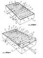
- the grid 1 essentially comprises a sheet of parallel bars 2 coming from foundry with parallel transverse bars 3, the bars 2 and 3 defining between them parallel lights 4 located on one side of the grid, transverse parallel lights 5 located on the opposite side of the grid and intermediate parallel transverse lights 6 located substantially in the center of this grid. Lights 4 to 6 allow the evacuation of runoff.
- the grid 1 is elastically fixed in a frame 7, in this case of rectangular shape, integral with a roadway (not shown) for closing a gutter, it being understood that it could be used to close a manhole.
- the grid 1 comprises two internal bars 2 elastically deformable relative to the other bars 2 and allowing the removable attachment of the grid in the frame 7.
- the two elastically deformable bars 2 are located opposite each other and are respectively adjacent to the two outer end bars 2 located near the walls constituting the width of the frame 7 when the grid 1 is fixed in this case. latest.
- the two elastically deformable bars 2 are integral at each of their ends with a transverse bar 3 and carry at their opposite free ends respectively two fingers 8 that can be locked to the frame 7 as will be seen later. and which are directed in opposite directions from each other in a direction parallel to the width of the frame so as to be substantially diagonally opposite.
- Each locking pin 8 is located in extension of the corresponding inner bar 2 and is offset downward relative to the outer surface of this bar so as to be disposed under a corresponding full outer edge 9 of the grid 1 and whose outer surface is located in the same plane as that of the inner bar 2.
- the two solid outer edges 9 of the grid respectively depart from two diagonally opposite corners of the grid while extending in parallel in opposite directions from one another over a determined distance on one side of the grid, each of these solid edges 9 being intended to be facing a portion of the longitudinal wall of the frame 7 when the grid is fixed therein.
- Each locking finger 8, being housed under the solid outer edge 9 of the grid extending over a length substantially equal to the width of this edge, is thus protected from shocks during the manufacture of the grids.
- each locking pin 8 is located immediately below its full outer edge 9 and thus protected from the outside, when the grids are brought in bulk in a recovery tank after manufacture, the locking fingers can not undergo shocks when the grids collide with each other.
- each locking finger 8 is not only protected from the outside by the edge 9, but is also virtually invisible from the outside, thus making it more difficult to access the lock finger for malicious people.
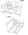
- Each locking pin 8 can elastically engage in a hook-shaped portion 10 secured to the inner face of the longitudinal wall of the frame 7 and located near a corner of this frame, the two hook-shaped portions 10 are of course located in the vicinity of the two diagonally opposite corners of this frame.
- Each hook-shaped portion 10 extends substantially perpendicularly to a seating surface 11 itself perpendicular to the longitudinal wall of the frame 7.
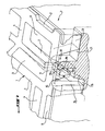
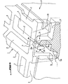
- each locking pin 8 which extends approximately perpendicularly below its solid outer edge 9, comprises a curvilinear ramp 8a guiding the finger 8 on the upper rounded end 10a of the locking hook-shaped part 10 and an upper free end in the form of a rounded nose 8b for snap-fastening engagement in the hook-shaped portion 10 as shown in FIG. figure 7 .
- the figure 8 shows the position of each locking finger 8 when the grid 1 is simply placed in the frame 7 before exerting on the grid the downward force for embedding the locking fingers respectively in their locking hooks 10.
- the figure 8 shows that the spout 8b of each locking finger 8 bears on the rounded upper end edge 10a of the locking hook-shaped portion 10.
- the rounded portions of the spout 8b of the finger 8 and the 10a end of the hook-shaped portion 10 cooperate to facilitate the unlocking of the finger 8 of the part 10 during a lifting force of the corresponding end of the gate by an operating tool, such as a mine bar 12.
- the grid 1 further comprises four support feet 13 located respectively at the four corners of the grid and which bear respectively on the four seating surfaces 11 located at each corner of the frame 7 when the grid is fixed in this frame.
- the two hook-lock portions 10 exert respectively on the two fingers of locking 8 a force maintaining the support legs 13 resting on the seating surfaces 11.
- the grid also comprises four other support feet 14 integral with the ends of two transverse plates 15 extending perpendicularly below the upper surface of the grid 1 at each inner parallel bar 2 adjacent to the corresponding elastically deformable inner bar 2.
- the four legs of the support 14 are held in abutment by the locking means 8 and 10, respectively on four seating surfaces 16 in extension of the seating surfaces 11 but at a lower level relative to these.
- the feet 14 and the stiffening plates 15 make it possible to eliminate any bending or deformation of the grid during the passage of heavy vehicles thereon.
- each locking pin 8 since it is between two support legs 13 and 14 projecting further below the gate than the finger, is even better protected during the manufacture of the grid.
- the frame 7 being set up and fixed on a floor for example, simply position the grid 1 to the right of the frame 7.
- the locking fingers 8 will then come into contact with the upper ends of the locking hook-shaped portions 10 as shown in FIG. figure 8 and, under the effect of a force exerted on at least one of the ends of the grid, the locking fingers 8 are elastically inserted by force into their respective hooks 10.
- figure 7 shows in phantom the elastic deformation undergone for each bar 2 during the engagement of the finger 8 in its locking hook 10.
- the elastic deformation of each internal bar 2 is made possible by the fact that the grid is made of cast iron GS (spheroidal graphite).
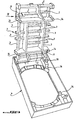
- the grid 1 can be manually lifted by gripping the outer bar 2 and it can pivot relatively to the frame 7 by its opposite side until it is brought to its open position represented in figure 3 to which it is held, at an angular position of opening of about 120 °, relative to the frame 7 by the two feet 13 located on the pivoting side of the gate and whose free ends are braced in support of a part on the hook-shaped portion 10 and on the other hand on an upstanding wall 17 integral with the longitudinal wall of the frame 7 opposite the frame 10 and extending perpendicularly above the corresponding seating surface 11
- the grid 1 is locked in its open position by bearing, by its corresponding side, on the two opposite seating surfaces 11. In its open position, the grid 1 can be disengaged from this position and removed completely by lifting
- the grid 1 can be invariably extracted from one side or the other by the tool 12 to unlock the corresponding finger 8 of its locking hook 10 and rotate the gate on its opposite side to open it in the direction shown on the figure 3 or open it the other way represented in figure 4 . It goes without saying that when the grid is unlocked on one side, the uprising of that side of the grid 1 allows an automatic disengagement of the other locking finger of its associated locking hook 10.
- the mounting direction of the grid 1 relative to the frame 7 can be performed independently of their relative orientations.
- the grid 1 may nevertheless be fixed in it thanks to the particular arrangement of the locking means 8, 10.
- the grid 1 can always be fixed in it so that the lights 4 are actually located sidewalk, the lights 5 being located on the road side.
- the frame 7 can be arranged without particular constraint.
- the grid may be fixed in one direction or the other in this frame if such a grid was of the type comprising parallel and transverse bars defining regular lights oriented in the same direction.
- the extraction of the grid from its frame is performed by a tool not acting directly on the elastically deformable bar but on the rigid outer end bar adjacent to the elastically deformable inner bar, which eliminates completely any risk of deterioration of the latter.
Landscapes
- Engineering & Computer Science (AREA)
- Life Sciences & Earth Sciences (AREA)
- Mining & Mineral Resources (AREA)
- General Engineering & Computer Science (AREA)
- Public Health (AREA)
- Water Supply & Treatment (AREA)
- Environmental & Geological Engineering (AREA)
- General Life Sciences & Earth Sciences (AREA)
- Health & Medical Sciences (AREA)
- Paleontology (AREA)
- Civil Engineering (AREA)
- Hydrology & Water Resources (AREA)
- Structural Engineering (AREA)
- Road Paving Structures (AREA)
- Sewage (AREA)
- Refuge Islands, Traffic Blockers, Or Guard Fence (AREA)
- Paper (AREA)
- Glass Compositions (AREA)
- Constitution Of High-Frequency Heating (AREA)
- Specific Sealing Or Ventilating Devices For Doors And Windows (AREA)
- Air-Flow Control Members (AREA)
- External Artificial Organs (AREA)
- Bidet-Like Cleaning Device And Other Flush Toilet Accessories (AREA)
- Baking, Grill, Roasting (AREA)
- Devices For Medical Bathing And Washing (AREA)
- Golf Clubs (AREA)
- Developing Agents For Electrophotography (AREA)
- Diaphragms For Electromechanical Transducers (AREA)
Claims (12)
- Gitter zum Einbauen in einen Rahmen (7) zum Verschließen einer Regenrinne oder dergleichen und umfassend sich kreuzende Stäbe (2, 3), wobei mindestens einer der Stäbe (2) des Gitters (1) im Verhältnis zu den anderen Stäben (2) elastisch verformbar ist und einen Zapfen (8) umfasst, der an dem Rahmen (7) verriegelt werden kann, so dass das Gitter (1) elastisch an dem Rahmen (7) befestigt ist, wobei der elastisch verformbare Stab ein innerer Stab (2) des Gitters (1) ist ein freies Ende aufweist, das den Verriegelungszapfen (8) umfasst, dadurch gekennzeichnet, dass der Verriegelungszapfen (8) sich unterhalb eines massiven Außenrandes (9) des Gitters befindet und sich quer zu dem elastisch verformbaren Stab (2) erstreckt, so dass der Zapfen (8) einerseits geschützt ist und andererseits von außen in der Position des in den Rahmen (7) eingebauten Gitters (1) nicht sichtbar ist.
- Gitter nach Anspruch 1, dadurch gekennzeichnet, dass es einen zweiten elastisch verformbaren inneren Stab (2) umfasst, der an seinem freien Ende einen Zapfen (8) aufweist, der mit dem Rahmen (7) verriegelt werden kann, und der sich unterhalb eines anderen massiven Außenrandes (9) des Gitters befindet, gegenüber dem massiven Außenrand (9) zum Schutz des Zapfens (8) des ersten inneren Stabs (8), und der sich quer zu dem zweiten elastisch verformbaren Stab (2) erstreckt, damit das Gitter (1) elastisch in dem Rahmen (7) befestigt werden kann, und zwar unabhängig von ihren relativen Ausrichtungen.
- Gitter nach Anspruch 2, gekennzeichnet durch ein Gelege aus parallelen Stäben (2), welche die beiden elastisch verformbaren inneren Stäbe (2) umfassen, und aus quer liegenden Stäben (3), und dass jeder Verriegelungszapfen (8) in der Verlängerung des entsprechenden inneren Stabs (2) liegt und im Verhältnis zur äußeren Oberfläche dieses Stabs nach unten versetzt ist, um unterhalb des entsprechenden massiven Außenrands (9) des Gitters (1) angeordnet zu sein, und dessen äußere Oberfläche sich in der gleichen Ebene befindet wie die des inneren Stabs (2).
- Gitter nach einem der vorhergehenden Ansprüche, dadurch gekennzeichnet, dass jeder Verriegelungszapfen (8) unter Druck elastisch in einen Abschnitt eingreift, der die Form eines Verriegelungshakens (10) hat, der mit der Innenseite der entsprechenden Seitenwand des Rahmens (7) einstückig ist und sich in der Nähe einer Ecke dieses Rahmens befindet.
- Gitter nach Anspruch 4, dadurch gekennzeichnet, dass jeder Verriegelungszapfen (8) eine gekrümmte Leitrampe (8a) umfasst, die sich in einem freien Ende (8b) als gerundeter Ansatz verlängert, der in den Abschnitt einrastet, der die Form eines Verriegelungshakens (10) hat, ebenfalls mit einem gerundeten freien Ende (10a), und elastisch ein Entriegeln des Zapfens (8) aus dem hakenförmigen Abschnitt (10) ermöglicht, wenn das Gitter (1) aus dem Rahmen (7) gezogen wird, um es in seine Öffnungsposition zu bringen.
- Gitter nach einem der Ansprüche 2 bis 5, dadurch gekennzeichnet, dass es auf einer Seite oder auf einer dieser entgegengesetzten Seite aus dem Rahmen (7) gezogen werden kann durch Einführen eines Werkzeugs (12), wie etwa einer Bohrstange, in den Raum, der zwischen dem Gitter (7) und dem äußeren Stab (2) des Gitters neben dem elastisch verformbaren inneren Stab (2) vorhanden ist, und durch Aufbringen unterhalb des äußeren Stabs (2) einer Kraft zum Anheben und Entriegeln des Gitters (1).
- Gitter nach einem der Ansprüche 4 bis 6, dadurch gekennzeichnet, dass es vier Stützfüße (13) umfasst, die sich jeweils in vier Ecken des Gitters (1) befinden und jeweils sich auf einer Auflagefläche (11) abstützend gehalten werden, die sich in einer Ecke des Rahmens (7) befindet, durch die Verriegelungskraft, die durch die beiden hakenförmigen Abschnitte (10) auf die beiden Verriegelungsstifte (8) ausgeübt wird.
- Gitter nach einem der Ansprüche 2 bis 7, dadurch gekennzeichnet, dass es, sobald es auf der einen oder anderen Seite entriegelt wurde, bis zu seiner entgegengesetzten Seite im Verhältnis zum Rahmen (7) verschwenkbar ist, bis es an dem Rahmen in einer Winkelöffnungsposition von ungefähr 120° festgehalten wird.
- Gitter nach Anspruch 8, in Kombination mit Anspruch 7 genommen, dadurch gekennzeichnet, dass es auf dem Rahmen (7) in seiner Öffnungsposition durch zwei seiner Stützfüße (13) festgehalten wird, die sich auf derselben Seite befinden und jeweils auf zwei aufrechten Wänden (10, 17) des Rahmens (7) abstützend blockiert sind, und von denen einer aus einem Abschnitt besteht, der die Form eines Verriegelungshakens (10) hat.
- Gitter nach einem der vorhergehenden Ansprüche, dadurch gekennzeichnet, dass es nach Entriegeln des Verriegelungszapfens (8) unmittelbar und vollständig aus dem Rahmen (7) gezogen werden kann.
- Gitter nach einem der Ansprüche 2 bis 10, dadurch gekennzeichnet, dass die Verriegelungsstifte (8) im Wesentlichen diagonal entgegengesetzt sind.
- Gitter nach einem der Ansprüche 3 bis 11, dadurch gekennzeichnet, dass die parallelen (2) und quer liegenden (3) Stäbe auf einer Seite des Gitters (1) parallele Einlässe (4) für den Durchgang von Regenwasser und auf der anderen Seite quer liegende Einlässe (5) für den Durchgang von Regenwasser definieren und das Gitter (1) innerhalb des Rahmens (7) befestigt ist, so dass die parallelen Einlässe (4) auf der Bürgersteigseite und die quer liegenden Einlässe (5) auf der Fahrbahnseite angeordnet sind, und zwar unabhängig von der Befestigungsrichtung des Rahmens (7) an der Fahrbahn.
Priority Applications (1)
| Application Number | Priority Date | Filing Date | Title |
|---|---|---|---|
| SI200331503T SI1525354T1 (sl) | 2002-08-02 | 2003-07-29 | Rešetka za zapiranje odtoka ali podobnega |
Applications Claiming Priority (3)
| Application Number | Priority Date | Filing Date | Title |
|---|---|---|---|
| FR0209895A FR2843139B1 (fr) | 2002-08-02 | 2002-08-02 | "grille pour obtruer un caniveau ou analogue" |
| FR0209895 | 2002-08-02 | ||
| PCT/FR2003/002391 WO2004015213A2 (fr) | 2002-08-02 | 2003-07-29 | Grille pour obturer un caniveau ou analogue |
Publications (2)
| Publication Number | Publication Date |
|---|---|
| EP1525354A2 EP1525354A2 (de) | 2005-04-27 |
| EP1525354B1 true EP1525354B1 (de) | 2008-12-03 |
Family
ID=30129668
Family Applications (1)
| Application Number | Title | Priority Date | Filing Date |
|---|---|---|---|
| EP03755649A Expired - Lifetime EP1525354B1 (de) | 2002-08-02 | 2003-07-29 | Gitter zum verschliessen einer rinne oder ähnlichem |
Country Status (16)
| Country | Link |
|---|---|
| US (1) | US7303669B2 (de) |
| EP (1) | EP1525354B1 (de) |
| JP (1) | JP2005534837A (de) |
| CN (1) | CN1330832C (de) |
| AT (1) | ATE416279T1 (de) |
| AU (1) | AU2003273490B2 (de) |
| DE (1) | DE60325058D1 (de) |
| DK (1) | DK1525354T3 (de) |
| ES (1) | ES2318159T3 (de) |
| FR (1) | FR2843139B1 (de) |
| ME (1) | ME00583A (de) |
| PL (1) | PL201236B1 (de) |
| PT (1) | PT1525354E (de) |
| RS (1) | RS50733B (de) |
| SI (1) | SI1525354T1 (de) |
| WO (1) | WO2004015213A2 (de) |
Families Citing this family (32)
| Publication number | Priority date | Publication date | Assignee | Title |
|---|---|---|---|---|
| GB0220165D0 (en) * | 2002-08-30 | 2002-10-09 | Saint Gobain Pipelines Plc | A drainage assembly |
| DE20302195U1 (de) * | 2003-02-12 | 2004-06-17 | Hydrotec Technologies Gmbh & Co. Kg | Entwässerungsvorrichtung |
| EP1606464A1 (de) | 2003-03-25 | 2005-12-21 | Aco Severin Ahlmann Gmbh & Co. Kg | Abdeckungsanordnug |
| DE102004023831B4 (de) * | 2004-05-13 | 2009-09-03 | Aco Severin Ahlmann Gmbh & Co. Kg | Abgedeckter Kunststoffriegel |
| FR2897880B1 (fr) * | 2006-02-28 | 2009-11-06 | Saint Gobain Pam Sa | Dispositif de fermeture. |
| ES2338290B1 (es) * | 2007-08-24 | 2011-02-10 | Cofunco, S.A. | Registro de servicios provisto de un dispositivo de cierre y de un util de apertura o cierre portatil de bolsillo. |
| USD582527S1 (en) * | 2008-03-25 | 2008-12-09 | Wang Jianbo | Floor drain device |
| GB2470074A (en) * | 2009-05-08 | 2010-11-10 | Savage Peter Ltd | A hinged gully grating assembly having a deformable engagement means |
| DE102010036509A1 (de) * | 2010-07-20 | 2012-01-26 | Aco Severin Ahlmann Gmbh & Co. Kg | Vorrichtung zum Arretieren einer Abdeckung auf einer Entwässerungsrinne oder dergleichen Entwässerungselement |
| DE102010061554B4 (de) * | 2010-12-23 | 2016-04-28 | Heinrich Meier Eisengiesserei Gmbh & Co Kg | Abdeckvorrichtung für eine Entwässerungsmulde |
| US20120210653A1 (en) * | 2011-02-22 | 2012-08-23 | Consolidated Edison Company Of New York, Inc. | Roadway grating system and method thereof |
| US8511295B2 (en) * | 2011-04-13 | 2013-08-20 | Rolf Bürkle | Modular-hinged grilling grate system |
| FR2986022B1 (fr) * | 2012-01-25 | 2015-02-20 | Norinco | Regard de chaussee a cadre et tampon ameliores |
| DE102012110941A1 (de) * | 2012-11-14 | 2014-05-15 | ACO Severin Ahlmann GmbH & Co Kommanditgesellschaft | Verschluss zum Verriegeln einer Abdeckung |
| CA2837496C (en) * | 2012-12-18 | 2016-12-13 | Canada Pipe Company ULC | Locking mechanism for a cover |
| CN103306363A (zh) * | 2013-06-25 | 2013-09-18 | 王秀东 | 防盗井篦子及使用方法 |
| US9347679B2 (en) * | 2014-01-13 | 2016-05-24 | Lynne Bruhnke | Grille door opener |
| CA157036S (en) | 2014-06-11 | 2015-03-05 | Decor Grates Inc | Floor register grille |
| USD763432S1 (en) * | 2014-09-18 | 2016-08-09 | Decor Grates Incorporated | Floor register grille |
| USD759791S1 (en) * | 2014-10-16 | 2016-06-21 | Oatey Co. | Grate |
| WO2016112928A1 (en) * | 2015-01-13 | 2016-07-21 | Knauf Gips Kg | Air outlet for a ventilation device |
| CA2925260C (en) * | 2016-02-22 | 2023-09-19 | Robert A. Diplacido | Elevator trench drain |
| USD787028S1 (en) | 2016-03-21 | 2017-05-16 | Zurn Industries, Llc | Elevator trench drain |
| USD789497S1 (en) * | 2016-05-31 | 2017-06-13 | Oatey Co. | Circular grate |
| USD788889S1 (en) * | 2016-05-31 | 2017-06-06 | Oatey Co. | Circular grate |
| JP6916978B2 (ja) * | 2017-07-18 | 2021-08-11 | 有限会社ウイング | グレーチング外れ止め装置 |
| RU2663589C1 (ru) * | 2017-08-04 | 2018-08-07 | Игорь Викторович Прохоров | Устройство и способ фиксации решётки на посадочном месте устройства, препятствующего проникновению предметов |
| USD831550S1 (en) * | 2018-02-06 | 2018-10-23 | John E. McLoughlin | Safety cover for automotive brake pedal |
| FR3091883B1 (fr) | 2019-01-23 | 2022-07-29 | Ej Emea | Dispositif de sécurisation du verrouillage d’un système d’obturation d’un regard |
| US11795703B2 (en) | 2021-02-04 | 2023-10-24 | Zurn Industries, Llc | Elevator trench drain |
| US12534899B2 (en) * | 2022-12-09 | 2026-01-27 | Midwest Design Group | Trench drains with suspended grates |
| US12546102B2 (en) * | 2023-02-23 | 2026-02-10 | Advanced Drainage Systems, Inc. | Linear or trench drain systems |
Family Cites Families (13)
| Publication number | Priority date | Publication date | Assignee | Title |
|---|---|---|---|---|
| US791381A (en) * | 1904-06-27 | 1905-05-30 | John M Thompson | Receiver or catch-basin. |
| US1056801A (en) * | 1911-11-04 | 1913-03-25 | August W Kurz | Vault-head. |
| US3881832A (en) * | 1974-05-16 | 1975-05-06 | Harry A Maguire | Low profile protective insert for sewers |
| GB1539677A (en) * | 1977-03-23 | 1979-01-31 | Selflevel Covers Ag | Grating |
| GB2079355B (en) * | 1980-06-26 | 1983-10-12 | British Steel Corp | Locking gully gratings or manhole covers |
| EP0280872B1 (de) * | 1987-02-02 | 1992-07-01 | Von Roll Ag | Einrichtung zum Sichern einer eine Öffnung abschliessenden Abdeckung |
| CH675604A5 (de) * | 1988-04-15 | 1990-10-15 | Von Roll Ag | |
| FR2669655B1 (fr) * | 1990-11-27 | 1993-03-05 | Pont A Mousson | Moyens de liaison pour pieces de voirie, et piece de voirie correspondante. |
| FR2674560B1 (fr) * | 1991-03-28 | 1993-06-11 | Pont A Mousson | Dispositif de couronnement d'une cheminee d'acces ou d'evacuation. |
| FR2716472B1 (fr) * | 1994-02-18 | 1996-05-03 | Norinco | Grille pour obturer des regards de chaussée. |
| FR2723118B1 (fr) * | 1994-07-29 | 1998-02-13 | Pont A Mousson | Dispositif de voirie |
| CN2215530Y (zh) * | 1994-11-01 | 1995-12-20 | 季国华 | 防盗格栅 |
| CN2319461Y (zh) * | 1998-03-12 | 1999-05-19 | 詹黄阿藤 | 落水栅板 |
-
2002
- 2002-08-02 FR FR0209895A patent/FR2843139B1/fr not_active Expired - Fee Related
-
2003
- 2003-07-29 DE DE60325058T patent/DE60325058D1/de not_active Expired - Lifetime
- 2003-07-29 US US10/523,554 patent/US7303669B2/en not_active Expired - Fee Related
- 2003-07-29 ME MEP-17/09A patent/ME00583A/xx unknown
- 2003-07-29 WO PCT/FR2003/002391 patent/WO2004015213A2/fr not_active Ceased
- 2003-07-29 RS YUP-364/04A patent/RS50733B/sr unknown
- 2003-07-29 AT AT03755649T patent/ATE416279T1/de active
- 2003-07-29 PT PT03755649T patent/PT1525354E/pt unknown
- 2003-07-29 EP EP03755649A patent/EP1525354B1/de not_active Expired - Lifetime
- 2003-07-29 CN CNB038186365A patent/CN1330832C/zh not_active Expired - Fee Related
- 2003-07-29 ES ES03755649T patent/ES2318159T3/es not_active Expired - Lifetime
- 2003-07-29 JP JP2004526957A patent/JP2005534837A/ja active Pending
- 2003-07-29 AU AU2003273490A patent/AU2003273490B2/en not_active Ceased
- 2003-07-29 SI SI200331503T patent/SI1525354T1/sl unknown
- 2003-07-29 DK DK03755649T patent/DK1525354T3/da active
- 2003-07-29 PL PL373070A patent/PL201236B1/pl not_active IP Right Cessation
Also Published As
| Publication number | Publication date |
|---|---|
| WO2004015213A3 (fr) | 2004-04-08 |
| ME00583A (en) | 2011-12-20 |
| EP1525354A2 (de) | 2005-04-27 |
| PL201236B1 (pl) | 2009-03-31 |
| HK1076849A1 (en) | 2006-01-27 |
| JP2005534837A (ja) | 2005-11-17 |
| US20050230295A1 (en) | 2005-10-20 |
| FR2843139B1 (fr) | 2005-03-18 |
| PL373070A1 (en) | 2005-08-08 |
| ATE416279T1 (de) | 2008-12-15 |
| US7303669B2 (en) | 2007-12-04 |
| FR2843139A1 (fr) | 2004-02-06 |
| PT1525354E (pt) | 2009-03-05 |
| AU2003273490B2 (en) | 2007-06-28 |
| AU2003273490A1 (en) | 2004-02-25 |
| CN1330832C (zh) | 2007-08-08 |
| WO2004015213A2 (fr) | 2004-02-19 |
| RS50733B (sr) | 2010-08-31 |
| DK1525354T3 (da) | 2009-03-16 |
| SI1525354T1 (sl) | 2009-04-30 |
| CN1675438A (zh) | 2005-09-28 |
| ES2318159T3 (es) | 2009-05-01 |
| DE60325058D1 (de) | 2009-01-15 |
| YU36404A (sh) | 2005-09-19 |
Similar Documents
| Publication | Publication Date | Title |
|---|---|---|
| EP1525354B1 (de) | Gitter zum verschliessen einer rinne oder ähnlichem | |
| CA2577042C (fr) | Dispositif permettant d'obturer un cadre, comprenant un panneau monte articule amovible sur le cadre | |
| CA2337276C (fr) | Dispositif d'obturation a verrouillage selectif | |
| EP2543800B1 (de) | Verriegelungs- und Entriegelungsvorrichtung mindestens eines Abdeckelements auf einem Gestellrahmen dieses Elements | |
| BE1007921A3 (fr) | Dispositif pour le coffrage de plafond. | |
| EP1297225B1 (de) | Strassenbaueinrichtung mit scharnierdeckel | |
| EP1160382B1 (de) | Einstiegschacht mit angelenktem Deckel und Diebstahlsicherungsvorrichtung für eine Ausschachtung im Boden | |
| EP1091046B1 (de) | Verschlussvorrichtung für einen Kontroll- oder Inspektionsschacht | |
| EP0681066A1 (de) | Vorrichtung zur gelenkigen Verbindung eines Deckels auf einem Rahmen, nähmlich zum Schliessen einer Öffnung in einer Fahrbahn | |
| EP0698692B1 (de) | Abdeckung, insbesondere für den Zugangsschacht zu einem Hydranten, und die sie bildenden Elemente | |
| FR3011694A1 (fr) | Dispositif formant caniveau a securite amelioree | |
| EP0407680A1 (de) | Verfahren zum Verbinden einer vorgefertigten Gerüstbühne mit einer horizontalen Traverse, und vorgefertigte Gerüstbühne dazu | |
| CH661605A5 (fr) | Dispositif consigneur et deconsigneur pour un objet utilitaire, tels qu'un chariot a bagages. | |
| EP0434481B1 (de) | Vorrichtung zur lösbaren Verankerung eines Pfostens im Boden, Sockel und Pfosten, der eine derartige Vorrichtung enthält, und Entriegelungswerkzeug für diese Vorrichtung | |
| WO2025224028A1 (fr) | Dispositif de couverture pour caniveau | |
| EP4556635A1 (de) | Vorrichtung zum sekundärschliessen einer unterirdischen kammer | |
| EP1553233B1 (de) | Bodenablauf | |
| EP1400634A1 (de) | Verriegelungselement für einen Gitterrost auf einer Entwässerungsrinne und Werkzeug zum Entfernen desselben | |
| FR2826679A1 (fr) | Dispositif de maintien en position d'une boite d'attente par rapport a une banche metallique | |
| FR2570210A2 (fr) | Dispositif consigneur et deconsigneur pour objets utilitaires, tels que des chariots a bagages | |
| WO2010004183A1 (fr) | Systeme et procede de manutention d'une plaque lourde | |
| FR2905387A1 (fr) | Support depliant pour panneau de signalisation routiere. | |
| CH655751A5 (fr) | Plaque-couvercle pour chambres de visite ou puits d'acces. | |
| FR2802589A1 (fr) | Dispositif d'immobilisation d'un container sur un chassis | |
| FR2896003A1 (fr) | Dispositif de couverture notamment d'une piscine |
Legal Events
| Date | Code | Title | Description |
|---|---|---|---|
| PUAI | Public reference made under article 153(3) epc to a published international application that has entered the european phase |
Free format text: ORIGINAL CODE: 0009012 |
|
| 17P | Request for examination filed |
Effective date: 20050218 |
|
| AK | Designated contracting states |
Kind code of ref document: A2 Designated state(s): AT BE BG CH CY CZ DE DK EE ES FI FR GB GR HU IE IT LI LU MC NL PT RO SE SI SK TR |
|
| AX | Request for extension of the european patent |
Extension state: AL LT LV MK |
|
| RIN1 | Information on inventor provided before grant (corrected) |
Inventor name: MONNERET, JEAN-JACQUES |
|
| RAX | Requested extension states of the european patent have changed |
Extension state: MK Payment date: 20050218 |
|
| REG | Reference to a national code |
Ref country code: HK Ref legal event code: DE Ref document number: 1076849 Country of ref document: HK |
|
| GRAP | Despatch of communication of intention to grant a patent |
Free format text: ORIGINAL CODE: EPIDOSNIGR1 |
|
| GRAS | Grant fee paid |
Free format text: ORIGINAL CODE: EPIDOSNIGR3 |
|
| GRAA | (expected) grant |
Free format text: ORIGINAL CODE: 0009210 |
|
| AK | Designated contracting states |
Kind code of ref document: B1 Designated state(s): AT BE BG CH CY CZ DE DK EE ES FI FR GB GR HU IE IT LI LU MC NL PT RO SE SI SK TR |
|
| AX | Request for extension of the european patent |
Extension state: MK |
|
| REG | Reference to a national code |
Ref country code: GB Ref legal event code: FG4D Free format text: NOT ENGLISH |
|
| REG | Reference to a national code |
Ref country code: CH Ref legal event code: EP |
|
| REG | Reference to a national code |
Ref country code: IE Ref legal event code: FG4D Free format text: LANGUAGE OF EP DOCUMENT: FRENCH |
|
| REF | Corresponds to: |
Ref document number: 60325058 Country of ref document: DE Date of ref document: 20090115 Kind code of ref document: P |
|
| REG | Reference to a national code |
Ref country code: CH Ref legal event code: NV Representative=s name: TROESCH SCHEIDEGGER WERNER AG |
|
| REG | Reference to a national code |
Ref country code: RO Ref legal event code: EPE |
|
| REG | Reference to a national code |
Ref country code: PT Ref legal event code: SC4A Free format text: AVAILABILITY OF NATIONAL TRANSLATION Effective date: 20090225 |
|
| REG | Reference to a national code |
Ref country code: DK Ref legal event code: T3 |
|
| REG | Reference to a national code |
Ref country code: SE Ref legal event code: TRGR |
|
| REG | Reference to a national code |
Ref country code: GR Ref legal event code: EP Ref document number: 20090400656 Country of ref document: GR |
|
| REG | Reference to a national code |
Ref country code: ES Ref legal event code: FG2A Ref document number: 2318159 Country of ref document: ES Kind code of ref document: T3 |
|
| REG | Reference to a national code |
Ref country code: HK Ref legal event code: GR Ref document number: 1076849 Country of ref document: HK |
|
| REG | Reference to a national code |
Ref country code: HU Ref legal event code: AG4A Ref document number: E005643 Country of ref document: HU |
|
| PLBE | No opposition filed within time limit |
Free format text: ORIGINAL CODE: 0009261 |
|
| STAA | Information on the status of an ep patent application or granted ep patent |
Free format text: STATUS: NO OPPOSITION FILED WITHIN TIME LIMIT |
|
| 26N | No opposition filed |
Effective date: 20090904 |
|
| PGFP | Annual fee paid to national office [announced via postgrant information from national office to epo] |
Ref country code: CY Payment date: 20090722 Year of fee payment: 7 |
|
| PG25 | Lapsed in a contracting state [announced via postgrant information from national office to epo] |
Ref country code: MC Free format text: LAPSE BECAUSE OF NON-PAYMENT OF DUE FEES Effective date: 20090731 |
|
| PGFP | Annual fee paid to national office [announced via postgrant information from national office to epo] |
Ref country code: GR Payment date: 20090730 Year of fee payment: 7 |
|
| PG25 | Lapsed in a contracting state [announced via postgrant information from national office to epo] |
Ref country code: LU Free format text: LAPSE BECAUSE OF NON-PAYMENT OF DUE FEES Effective date: 20090729 |
|
| PG25 | Lapsed in a contracting state [announced via postgrant information from national office to epo] |
Ref country code: CY Free format text: LAPSE BECAUSE OF NON-PAYMENT OF DUE FEES Effective date: 20100729 |
|
| PG25 | Lapsed in a contracting state [announced via postgrant information from national office to epo] |
Ref country code: GR Free format text: LAPSE BECAUSE OF NON-PAYMENT OF DUE FEES Effective date: 20110202 |
|
| PGFP | Annual fee paid to national office [announced via postgrant information from national office to epo] |
Ref country code: SE Payment date: 20130725 Year of fee payment: 11 Ref country code: PT Payment date: 20130129 Year of fee payment: 11 Ref country code: SK Payment date: 20130726 Year of fee payment: 11 Ref country code: EE Payment date: 20130722 Year of fee payment: 11 Ref country code: DK Payment date: 20130726 Year of fee payment: 11 Ref country code: BG Payment date: 20130723 Year of fee payment: 11 |
|
| PGFP | Annual fee paid to national office [announced via postgrant information from national office to epo] |
Ref country code: FI Payment date: 20140723 Year of fee payment: 12 |
|
| REG | Reference to a national code |
Ref country code: PT Ref legal event code: MM4A Free format text: LAPSE DUE TO NON-PAYMENT OF FEES Effective date: 20150129 |
|
| REG | Reference to a national code |
Ref country code: DK Ref legal event code: EBP Effective date: 20140731 |
|
| REG | Reference to a national code |
Ref country code: SE Ref legal event code: EUG |
|
| REG | Reference to a national code |
Ref country code: EE Ref legal event code: MM4A Ref document number: E002984 Country of ref document: EE Effective date: 20140731 |
|
| REG | Reference to a national code |
Ref country code: SK Ref legal event code: MM4A Ref document number: E 5039 Country of ref document: SK Effective date: 20140729 |
|
| PG25 | Lapsed in a contracting state [announced via postgrant information from national office to epo] |
Ref country code: EE Free format text: LAPSE BECAUSE OF NON-PAYMENT OF DUE FEES Effective date: 20140731 Ref country code: SK Free format text: LAPSE BECAUSE OF NON-PAYMENT OF DUE FEES Effective date: 20140729 Ref country code: PT Free format text: LAPSE BECAUSE OF NON-PAYMENT OF DUE FEES Effective date: 20150129 Ref country code: BG Free format text: LAPSE BECAUSE OF NON-PAYMENT OF DUE FEES Effective date: 20150331 |
|
| PG25 | Lapsed in a contracting state [announced via postgrant information from national office to epo] |
Ref country code: SE Free format text: LAPSE BECAUSE OF NON-PAYMENT OF DUE FEES Effective date: 20140730 |
|
| REG | Reference to a national code |
Ref country code: FR Ref legal event code: PLFP Year of fee payment: 13 |
|
| PG25 | Lapsed in a contracting state [announced via postgrant information from national office to epo] |
Ref country code: DK Free format text: LAPSE BECAUSE OF NON-PAYMENT OF DUE FEES Effective date: 20140731 |
|
| PGFP | Annual fee paid to national office [announced via postgrant information from national office to epo] |
Ref country code: NL Payment date: 20150722 Year of fee payment: 13 |
|
| PGFP | Annual fee paid to national office [announced via postgrant information from national office to epo] |
Ref country code: IE Payment date: 20150723 Year of fee payment: 13 Ref country code: RO Payment date: 20150720 Year of fee payment: 13 Ref country code: CZ Payment date: 20150728 Year of fee payment: 13 Ref country code: ES Payment date: 20150827 Year of fee payment: 13 Ref country code: CH Payment date: 20150722 Year of fee payment: 13 Ref country code: GB Payment date: 20150727 Year of fee payment: 13 |
|
| PGFP | Annual fee paid to national office [announced via postgrant information from national office to epo] |
Ref country code: SI Payment date: 20150716 Year of fee payment: 13 Ref country code: AT Payment date: 20150729 Year of fee payment: 13 Ref country code: HU Payment date: 20150804 Year of fee payment: 13 Ref country code: FR Payment date: 20150630 Year of fee payment: 13 Ref country code: TR Payment date: 20150724 Year of fee payment: 13 Ref country code: BE Payment date: 20150731 Year of fee payment: 13 |
|
| PGFP | Annual fee paid to national office [announced via postgrant information from national office to epo] |
Ref country code: IT Payment date: 20150730 Year of fee payment: 13 |
|
| PGFP | Annual fee paid to national office [announced via postgrant information from national office to epo] |
Ref country code: DE Payment date: 20150930 Year of fee payment: 13 |
|
| REG | Reference to a national code |
Ref country code: GR Ref legal event code: ML Ref document number: 20090400656 Country of ref document: GR Effective date: 20110202 |
|
| PG25 | Lapsed in a contracting state [announced via postgrant information from national office to epo] |
Ref country code: FI Free format text: LAPSE BECAUSE OF NON-PAYMENT OF DUE FEES Effective date: 20150729 |
|
| PG25 | Lapsed in a contracting state [announced via postgrant information from national office to epo] |
Ref country code: BE Free format text: LAPSE BECAUSE OF NON-PAYMENT OF DUE FEES Effective date: 20160731 |
|
| REG | Reference to a national code |
Ref country code: DE Ref legal event code: R119 Ref document number: 60325058 Country of ref document: DE |
|
| REG | Reference to a national code |
Ref country code: CH Ref legal event code: PL |
|
| REG | Reference to a national code |
Ref country code: NL Ref legal event code: MM Effective date: 20160801 |
|
| REG | Reference to a national code |
Ref country code: AT Ref legal event code: MM01 Ref document number: 416279 Country of ref document: AT Kind code of ref document: T Effective date: 20160729 |
|
| GBPC | Gb: european patent ceased through non-payment of renewal fee |
Effective date: 20160729 |
|
| PG25 | Lapsed in a contracting state [announced via postgrant information from national office to epo] |
Ref country code: LI Free format text: LAPSE BECAUSE OF NON-PAYMENT OF DUE FEES Effective date: 20160731 Ref country code: NL Free format text: LAPSE BECAUSE OF NON-PAYMENT OF DUE FEES Effective date: 20160801 Ref country code: HU Free format text: LAPSE BECAUSE OF NON-PAYMENT OF DUE FEES Effective date: 20160730 Ref country code: RO Free format text: LAPSE BECAUSE OF NON-PAYMENT OF DUE FEES Effective date: 20160729 Ref country code: FR Free format text: LAPSE BECAUSE OF NON-PAYMENT OF DUE FEES Effective date: 20160801 Ref country code: CH Free format text: LAPSE BECAUSE OF NON-PAYMENT OF DUE FEES Effective date: 20160731 Ref country code: DE Free format text: LAPSE BECAUSE OF NON-PAYMENT OF DUE FEES Effective date: 20170201 |
|
| REG | Reference to a national code |
Ref country code: FR Ref legal event code: ST Effective date: 20170331 |
|
| REG | Reference to a national code |
Ref country code: IE Ref legal event code: MM4A |
|
| PG25 | Lapsed in a contracting state [announced via postgrant information from national office to epo] |
Ref country code: CZ Free format text: LAPSE BECAUSE OF NON-PAYMENT OF DUE FEES Effective date: 20160729 Ref country code: SI Free format text: LAPSE BECAUSE OF NON-PAYMENT OF DUE FEES Effective date: 20160730 Ref country code: GB Free format text: LAPSE BECAUSE OF NON-PAYMENT OF DUE FEES Effective date: 20160729 Ref country code: AT Free format text: LAPSE BECAUSE OF NON-PAYMENT OF DUE FEES Effective date: 20160729 |
|
| REG | Reference to a national code |
Ref country code: SI Ref legal event code: KO00 Effective date: 20170407 |
|
| PG25 | Lapsed in a contracting state [announced via postgrant information from national office to epo] |
Ref country code: IE Free format text: LAPSE BECAUSE OF NON-PAYMENT OF DUE FEES Effective date: 20160729 |
|
| PG25 | Lapsed in a contracting state [announced via postgrant information from national office to epo] |
Ref country code: IT Free format text: LAPSE BECAUSE OF NON-PAYMENT OF DUE FEES Effective date: 20160729 |
|
| PG25 | Lapsed in a contracting state [announced via postgrant information from national office to epo] |
Ref country code: ES Free format text: LAPSE BECAUSE OF NON-PAYMENT OF DUE FEES Effective date: 20160730 |
|
| REG | Reference to a national code |
Ref country code: ES Ref legal event code: FD2A Effective date: 20181128 |
|
| PG25 | Lapsed in a contracting state [announced via postgrant information from national office to epo] |
Ref country code: TR Free format text: LAPSE BECAUSE OF NON-PAYMENT OF DUE FEES Effective date: 20160729 |