EP1296057A1 - Filtre à combustible intégré à un tube de calibrage pour un injecteur à combustible - Google Patents
Filtre à combustible intégré à un tube de calibrage pour un injecteur à combustible Download PDFInfo
- Publication number
- EP1296057A1 EP1296057A1 EP02256468A EP02256468A EP1296057A1 EP 1296057 A1 EP1296057 A1 EP 1296057A1 EP 02256468 A EP02256468 A EP 02256468A EP 02256468 A EP02256468 A EP 02256468A EP 1296057 A1 EP1296057 A1 EP 1296057A1
- Authority
- EP
- European Patent Office
- Prior art keywords
- calibration tube
- filter
- fuel filter
- fuel
- filtration
- Prior art date
- Legal status (The legal status is an assumption and is not a legal conclusion. Google has not performed a legal analysis and makes no representation as to the accuracy of the status listed.)
- Granted
Links
- 239000000446 fuel Substances 0.000 title claims abstract description 118
- 238000001914 filtration Methods 0.000 claims abstract description 56
- 239000002184 metal Substances 0.000 claims abstract description 7
- 229910052751 metal Inorganic materials 0.000 claims abstract description 7
- 229920001169 thermoplastic Polymers 0.000 claims abstract description 6
- 239000004416 thermosoftening plastic Substances 0.000 claims abstract description 6
- 229910001220 stainless steel Inorganic materials 0.000 claims description 6
- 239000010935 stainless steel Substances 0.000 claims description 6
- 239000004677 Nylon Substances 0.000 claims description 4
- 229920001778 nylon Polymers 0.000 claims description 4
- 238000005304 joining Methods 0.000 claims description 3
- 238000011144 upstream manufacturing Methods 0.000 claims description 3
- 238000002788 crimping Methods 0.000 claims description 2
- 230000013011 mating Effects 0.000 claims 1
- 230000008901 benefit Effects 0.000 description 6
- 239000002245 particle Substances 0.000 description 6
- 238000005299 abrasion Methods 0.000 description 3
- 239000000463 material Substances 0.000 description 3
- 238000001746 injection moulding Methods 0.000 description 2
- 238000004519 manufacturing process Methods 0.000 description 2
- 229910001369 Brass Inorganic materials 0.000 description 1
- 229910000906 Bronze Inorganic materials 0.000 description 1
- 230000002411 adverse Effects 0.000 description 1
- 239000010951 brass Substances 0.000 description 1
- 239000010974 bronze Substances 0.000 description 1
- 238000006243 chemical reaction Methods 0.000 description 1
- 238000002485 combustion reaction Methods 0.000 description 1
- 239000000356 contaminant Substances 0.000 description 1
- KUNSUQLRTQLHQQ-UHFFFAOYSA-N copper tin Chemical compound [Cu].[Sn] KUNSUQLRTQLHQQ-UHFFFAOYSA-N 0.000 description 1
- 239000003792 electrolyte Substances 0.000 description 1
- 239000011521 glass Substances 0.000 description 1
- 230000002452 interceptive effect Effects 0.000 description 1
- 150000002739 metals Chemical class 0.000 description 1
- 238000000034 method Methods 0.000 description 1
- 239000004033 plastic Substances 0.000 description 1
- 229920000642 polymer Polymers 0.000 description 1
- 238000005096 rolling process Methods 0.000 description 1
- 238000010008 shearing Methods 0.000 description 1
- 239000000126 substance Substances 0.000 description 1
- 239000012815 thermoplastic material Substances 0.000 description 1
Images

Classifications
-
- F—MECHANICAL ENGINEERING; LIGHTING; HEATING; WEAPONS; BLASTING
- F02—COMBUSTION ENGINES; HOT-GAS OR COMBUSTION-PRODUCT ENGINE PLANTS
- F02M—SUPPLYING COMBUSTION ENGINES IN GENERAL WITH COMBUSTIBLE MIXTURES OR CONSTITUENTS THEREOF
- F02M51/00—Fuel-injection apparatus characterised by being operated electrically
- F02M51/06—Injectors peculiar thereto with means directly operating the valve needle
- F02M51/061—Injectors peculiar thereto with means directly operating the valve needle using electromagnetic operating means
- F02M51/0625—Injectors peculiar thereto with means directly operating the valve needle using electromagnetic operating means characterised by arrangement of mobile armatures
- F02M51/0664—Injectors peculiar thereto with means directly operating the valve needle using electromagnetic operating means characterised by arrangement of mobile armatures having a cylindrically or partly cylindrically shaped armature, e.g. entering the winding; having a plate-shaped or undulated armature entering the winding
- F02M51/0667—Injectors peculiar thereto with means directly operating the valve needle using electromagnetic operating means characterised by arrangement of mobile armatures having a cylindrically or partly cylindrically shaped armature, e.g. entering the winding; having a plate-shaped or undulated armature entering the winding the armature acting as a valve or having a short valve body attached thereto
-
- F—MECHANICAL ENGINEERING; LIGHTING; HEATING; WEAPONS; BLASTING
- F02—COMBUSTION ENGINES; HOT-GAS OR COMBUSTION-PRODUCT ENGINE PLANTS
- F02M—SUPPLYING COMBUSTION ENGINES IN GENERAL WITH COMBUSTIBLE MIXTURES OR CONSTITUENTS THEREOF
- F02M51/00—Fuel-injection apparatus characterised by being operated electrically
- F02M51/06—Injectors peculiar thereto with means directly operating the valve needle
- F02M51/061—Injectors peculiar thereto with means directly operating the valve needle using electromagnetic operating means
- F02M51/0625—Injectors peculiar thereto with means directly operating the valve needle using electromagnetic operating means characterised by arrangement of mobile armatures
- F02M51/0664—Injectors peculiar thereto with means directly operating the valve needle using electromagnetic operating means characterised by arrangement of mobile armatures having a cylindrically or partly cylindrically shaped armature, e.g. entering the winding; having a plate-shaped or undulated armature entering the winding
- F02M51/0671—Injectors peculiar thereto with means directly operating the valve needle using electromagnetic operating means characterised by arrangement of mobile armatures having a cylindrically or partly cylindrically shaped armature, e.g. entering the winding; having a plate-shaped or undulated armature entering the winding the armature having an elongated valve body attached thereto
- F02M51/0682—Injectors peculiar thereto with means directly operating the valve needle using electromagnetic operating means characterised by arrangement of mobile armatures having a cylindrically or partly cylindrically shaped armature, e.g. entering the winding; having a plate-shaped or undulated armature entering the winding the armature having an elongated valve body attached thereto the body being hollow and its interior communicating with the fuel flow
-
- F—MECHANICAL ENGINEERING; LIGHTING; HEATING; WEAPONS; BLASTING
- F02—COMBUSTION ENGINES; HOT-GAS OR COMBUSTION-PRODUCT ENGINE PLANTS
- F02M—SUPPLYING COMBUSTION ENGINES IN GENERAL WITH COMBUSTIBLE MIXTURES OR CONSTITUENTS THEREOF
- F02M61/00—Fuel-injectors not provided for in groups F02M39/00 - F02M57/00 or F02M67/00
- F02M61/16—Details not provided for in, or of interest apart from, the apparatus of groups F02M61/02 - F02M61/14
- F02M61/165—Filtering elements specially adapted in fuel inlets to injector
-
- F—MECHANICAL ENGINEERING; LIGHTING; HEATING; WEAPONS; BLASTING
- F02—COMBUSTION ENGINES; HOT-GAS OR COMBUSTION-PRODUCT ENGINE PLANTS
- F02M—SUPPLYING COMBUSTION ENGINES IN GENERAL WITH COMBUSTIBLE MIXTURES OR CONSTITUENTS THEREOF
- F02M61/00—Fuel-injectors not provided for in groups F02M39/00 - F02M57/00 or F02M67/00
- F02M61/16—Details not provided for in, or of interest apart from, the apparatus of groups F02M61/02 - F02M61/14
- F02M61/20—Closing valves mechanically, e.g. arrangements of springs or weights or permanent magnets; Damping of valve lift
- F02M61/205—Means specially adapted for varying the spring tension or assisting the spring force to close the injection-valve, e.g. with damping of valve lift
Definitions
- An integrated fuel filter and calibration tube has been invented which eliminates the potential for release of particles from the filter element by abrasion with the calibration tube.
- the filter is contained within the calibration tube, yet still has at least 60 mm 2 of effective filtration surface area.
- the invention is a combination of a fuel injector and an integrated fuel filter and calibration tube comprising a fuel injector having a fuel flow channel therethrough and a spring inside the flow channel; and an integrated fuel filter and calibration tube inside the flow channel, the calibration tube contacting the spring, the fuel filter comprising a thermoplastic frame attached to the calibration tube, the frame having a proximal end, a distal end and at least one rib connecting the ends, the frame supporting filtration media to provide filtration of all fuel flowing through the fuel flow channel.
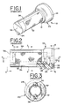
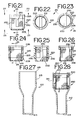
- FIGS. 5, 7 and 8 The integrated fuel filter and calibration tube 60 of the present invention is shown in combination with other components of a fuel injector 40 in FIG. 4.
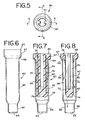
- the integrated fuel filter and calibration tube 60 is shown in FIGS. 5, 7 and 8. Its components include a housing or calibration tube 62, best seen in FIG. 6, and a filter element 70 best seen if FIGS. 9-14.
- the integrated fuel filter and calibration tube 60 has two major components, the calibration tube or housing 62 and the filter element 70.
- the calibration tube 62 is preferably an elongated, drawn, stainless steel tube. Although other metals could be used, stainless steel has the advantage of not reacting with components used in the wide variety of fuels that may be fed through injector 40.
- the metal tube 62 is rigidly attached to the filtration element 70 after both pieces are first produced independently.
- the tube 62 forms an elongated outside housing for the preferred filter element 70.
- the tube 62 has a main body portion 65, a neck 66 at the distal end of the housing and a shoulder 67 at the proximal end of the housing.
- the frame member 75 comprises a proximal end 76, a distal end 78 and at least one, and preferably two, rib members 80 joining the proximal end 76 to the distal 78.
- the two ribs 80 are spaced at 180° from each other around the perimeter of the filtration media cylinder.
- the proximal end 76 includes a shoulder 82 and a fuel inlet opening 84 along its axial center.
- the shoulder 82 is used to secure the filtration element 70 to the calibration tube 62.
- the outside diameter of the shoulder 82 of the proximal end of the filtration element is just smaller than the inside diameter of the shoulder section 67 of the calibration tube 62 but larger than the inside diameter of the housing body 65.
- the filtration element 70 is totally contained within the calibration tube 62. However, even fitting inside this small area, the preferred design still is made with an effective filtration surface area of at least 60 mm 2 .
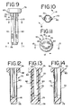
- the flow path of fuel through the filtration element is radially outward, as fuel enters through inlet opening 84 and is filtered as it passes outwardly through the filtration media 72 as shown by flow arrows in FIG. 8.
- the fuel then passes into the space 86 between the filter element 70 and the calibration tube 62, and flows out the opening 63 at the distal end of the calibration tube 62.
- the preferred frame material is a 35% glass filled 6-12 nylon.
- the preferred media 72 is a 30 micron woven nylon screen.
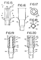
- FIGS. 15-20 is also an integrated fuel filter and calibration tube 100.
- the tube 110 is preferably made from stainless steel, and has a body portion 115 and an upper section 117.
- the filter element 120 is designed with a flow path of fuel through the filtration element radially inward. Fuel thus enters through media 122 held open by ribs 130 connecting the proximal end 126 and the base 128 of the filter frame. The flow then passes out an opening 134 in the base 128 of the filter element 120.
- the base 128 includes a shoulder 132 that is secured inside the upper section 117 of the calibration tube 110. The two pieces are held together by crimping in a center section 119 of the tube 110 to clamp over the shoulder 132 of the frame of the filter element 120 (FIGS. 19 and 20).
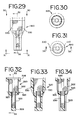
- FIGS. 21-28 A third embodiment of a combined filter element and calibration tube 200 is shown in FIGS. 21-28.
- the calibration tube 210 has a main body portion 215 that is used to totally contain the filter element 220.
- the frame of filter element 220 comprises longitudinal ribs 230 and a lateral rib 231 at the base.
- the proximal end 226 is completely open.
- the lateral rib 231 works with the distal end frame section 228 to hold filtration media 222 across the bottom. Fuel flow is thus in through the center open top and out through filtration media forming cylindrical side wall 223 or bottom 222. Flow can then enter the internal volume of the calibration tube 210 and flow out an opening 213 in the bottom thereof (see FIG. 28; showing flow arrows).
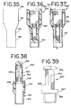
- FIG. 39 shows a sixth filtration element 520 that can be used with a calibration tube such as tube 60 that has a shoulder section 67 at its top.
- the flow is also radially inward through filtration media 522.
- the proximal end 526 and distal end 528 of the filter element 520 are connected by ribs 530.
- a shoulder 527 on distal end 528 is used to hold the filtration element 520 into a calibration tube so that the media 522 is exposed on the upstream side of the calibration tube.
Landscapes
- Engineering & Computer Science (AREA)
- Chemical & Material Sciences (AREA)
- Combustion & Propulsion (AREA)
- Mechanical Engineering (AREA)
- General Engineering & Computer Science (AREA)
- Physics & Mathematics (AREA)
- Electromagnetism (AREA)
- Fuel-Injection Apparatus (AREA)
- Filtration Of Liquid (AREA)
Applications Claiming Priority (2)
| Application Number | Priority Date | Filing Date | Title |
|---|---|---|---|
| US32375001P | 2001-09-19 | 2001-09-19 | |
| US323750P | 2001-09-19 |
Publications (2)
| Publication Number | Publication Date |
|---|---|
| EP1296057A1 true EP1296057A1 (fr) | 2003-03-26 |
| EP1296057B1 EP1296057B1 (fr) | 2011-01-05 |
Family
ID=23260543
Family Applications (1)
| Application Number | Title | Priority Date | Filing Date |
|---|---|---|---|
| EP02256468A Expired - Lifetime EP1296057B1 (fr) | 2001-09-19 | 2002-09-18 | Filtre à combustible intégré à un tube de calibrage pour un injecteur à combustible |
Country Status (5)
| Country | Link |
|---|---|
| US (1) | US20030052052A1 (fr) |
| EP (1) | EP1296057B1 (fr) |
| BR (1) | BR0203833B1 (fr) |
| CA (1) | CA2404247C (fr) |
| DE (1) | DE60238813D1 (fr) |
Cited By (5)
| Publication number | Priority date | Publication date | Assignee | Title |
|---|---|---|---|---|
| EP1806497A1 (fr) | 2006-01-10 | 2007-07-11 | Siemens Aktiengesellschaft | Injecteur |
| WO2009053219A1 (fr) * | 2007-10-18 | 2009-04-30 | Robert Bosch Gmbh | Injecteur de carburant |
| EP2426351A1 (fr) * | 2010-09-02 | 2012-03-07 | Continental Automotive GmbH | Réglage de l'ensemble de filtre de carburant et soupape d'injection |
| EP2549094A2 (fr) | 2011-07-18 | 2013-01-23 | Robert Bosch Gmbh | Soupape d'injection pour moteurs à combustion interne |
| EP3080434A1 (fr) * | 2013-12-13 | 2016-10-19 | Robert Bosch GmbH | Soupape d'injection de carburant |
Families Citing this family (35)
| Publication number | Priority date | Publication date | Assignee | Title |
|---|---|---|---|---|
| US6766825B2 (en) * | 2002-08-02 | 2004-07-27 | Bruce A. Antunez | Top-loaded replaceable flow control and particulate strainer |
| DE102005027617A1 (de) * | 2004-07-29 | 2006-03-23 | Ina-Schaeffler Kg | Ringfilter |
| EP1783360B1 (fr) * | 2005-11-02 | 2008-03-26 | Delphi Technologies, Inc. | Filtre interne pour un injecteur au carburant |
| US7617991B2 (en) * | 2006-03-31 | 2009-11-17 | Delphi Technologies, Inc. | Injector fuel filter with built-in orifice for flow restriction |
| JP2008194587A (ja) * | 2007-02-09 | 2008-08-28 | Toyo Roki Mfg Co Ltd | 濾過フィルタ及びその製造方法 |
| DE102013225829A1 (de) | 2013-12-13 | 2015-06-18 | Robert Bosch Gmbh | Brennstoffeinspritzventil |
| DE102013225817A1 (de) | 2013-12-13 | 2015-06-18 | Robert Bosch Gmbh | Brennstoffeinspritzventil |
| DE102013225812A1 (de) | 2013-12-13 | 2015-06-18 | Robert Bosch Gmbh | Brennstoffeinspritzventil |
| DE102013225840A1 (de) | 2013-12-13 | 2015-06-18 | Robert Bosch Gmbh | Brennstoffeinspritzventil |
| DE102013225820A1 (de) | 2013-12-13 | 2015-06-18 | Robert Bosch Gmbh | Brennstoffeinspritzventil |
| EP2896816A1 (fr) * | 2014-01-16 | 2015-07-22 | Continental Automotive GmbH | Ensemble de filtre pour injecteur de carburant, injecteur de carburant et procédé d'assemblage de l'ensemble de filtre |
| EP2910770B1 (fr) * | 2014-02-20 | 2018-09-19 | Continental Automotive GmbH | Ensemble de filtre et injecteur de carburant |
| DE102014225994A1 (de) | 2014-12-16 | 2016-06-16 | Robert Bosch Gmbh | Brennstoffeinspritzventil |
| DE102014226003A1 (de) | 2014-12-16 | 2016-06-16 | Robert Bosch Gmbh | Brennstoffeinspritzventil |
| DE102014225999A1 (de) | 2014-12-16 | 2016-06-16 | Robert Bosch Gmbh | Brennstoffeinspritzventil |
| FR3038938B1 (fr) * | 2015-07-17 | 2018-12-07 | Delphi Technologies Ip Limited | Filtre haute pression pour injecteur de carburant |
| DE102015226533A1 (de) | 2015-12-22 | 2017-06-22 | Robert Bosch Gmbh | Brennstoffeinspritzventil |
| DE102015226541A1 (de) | 2015-12-22 | 2017-06-22 | Robert Bosch Gmbh | Brennstoffeinspritzventil |
| DE102015226515A1 (de) | 2015-12-22 | 2017-06-22 | Robert Bosch Gmbh | Brennstoffeinspritzventil |
| DE102015226528A1 (de) | 2015-12-22 | 2017-06-22 | Robert Bosch Gmbh | Brennstoffeinspritzventil |
| DE102016226142A1 (de) | 2016-12-23 | 2018-06-28 | Robert Bosch Gmbh | Brennstoffeinspritzventil |
| DE102016226135A1 (de) | 2016-12-23 | 2018-06-28 | Robert Bosch Gmbh | Brennstoffeinspritzventil |
| JP6767293B2 (ja) * | 2017-03-23 | 2020-10-14 | 株式会社ニフコ | フィルター装置 |
| JP6782668B2 (ja) * | 2017-06-16 | 2020-11-11 | 日立オートモティブシステムズ株式会社 | 燃料噴射弁 |
| US10859051B2 (en) * | 2018-06-12 | 2020-12-08 | Delphi Technologies Ip Limited | Fuel injector with combined calibration tube, fuel filter, and pressure pulsation damping orifice |
| WO2020069726A1 (fr) * | 2018-10-02 | 2020-04-09 | Continental Automotive Gmbh | Filtre de réglage pour soupape d'injection de fluide et soupape d'injection de fluide associée |
| US20220136473A1 (en) * | 2020-10-30 | 2022-05-05 | Caterpillar Inc. | Filtration device for a common rail fuel injector |
| DE102020214154A1 (de) | 2020-11-11 | 2022-05-12 | Robert Bosch Gesellschaft mit beschränkter Haftung | Brennstoffeinspritzventil |
| US11852112B2 (en) * | 2020-11-24 | 2023-12-26 | Caterpillar Inc. | Fuel injector with internal filter element |
| DE102020215217A1 (de) | 2020-12-02 | 2022-06-02 | Robert Bosch Gesellschaft mit beschränkter Haftung | Brennstoffeinspritzventil |
| DE102020215218A1 (de) | 2020-12-02 | 2022-06-02 | Robert Bosch Gesellschaft mit beschränkter Haftung | Brennstoffeinspritzventil |
| DE102020215215A1 (de) | 2020-12-02 | 2022-06-02 | Robert Bosch Gesellschaft mit beschränkter Haftung | Brennstoffeinspritzventil |
| DE102020215621A1 (de) | 2020-12-10 | 2022-06-15 | Robert Bosch Gesellschaft mit beschränkter Haftung | Brennstoffeinspritzventil |
| DE102020215794A1 (de) | 2020-12-14 | 2022-06-15 | Robert Bosch Gesellschaft mit beschränkter Haftung | Brennstoffeinspritzventil |
| DE102022210875A1 (de) | 2022-10-14 | 2024-04-25 | Robert Bosch Gesellschaft mit beschränkter Haftung | Brennstoffeinspritzventil |
Citations (5)
| Publication number | Priority date | Publication date | Assignee | Title |
|---|---|---|---|---|
| US4608166A (en) | 1985-04-01 | 1986-08-26 | Filtertek, Inc. | Press fit filter |
| US5340032A (en) * | 1991-09-21 | 1994-08-23 | Robert Bosch Gmbh | Electromagnetically operated injection valve with a fuel filter that sets a spring force |
| US5921475A (en) * | 1997-08-07 | 1999-07-13 | Ford Motor Company | Automotive fuel injector |
| DE10102381A1 (de) * | 2000-01-19 | 2001-08-02 | Delphi Tech Inc | Federkraft-Kalibrierungsrohr für eine Kraftstoffeinspritzeinrichtung mit innen befestigtem Kraftstoffeinlaßfilter |
| EP1229239A2 (fr) * | 2001-02-02 | 2002-08-07 | Siemens VDO Automotive Corporation | Filtre et ajusteur combinés, pour injecteur de combustible |
Family Cites Families (5)
| Publication number | Priority date | Publication date | Assignee | Title |
|---|---|---|---|---|
| US4130622A (en) * | 1977-02-22 | 1978-12-19 | Abbott Laboratories | Method of making self-supporting tubular filter |
| US5252204A (en) * | 1992-08-20 | 1993-10-12 | Manufacturers Components, Inc. | Unimold filter |
| DE19647587A1 (de) * | 1996-11-18 | 1998-05-20 | Bosch Gmbh Robert | Brennstoffeinspritzventil |
| US6199775B1 (en) * | 2000-02-23 | 2001-03-13 | Siemens Automotive Corporation | Fuel injector filter unit having a composite housing |
| US6698664B2 (en) * | 2000-12-29 | 2004-03-02 | Siemens Automotive Corporation | Modular fuel injector having an integral or interchangeable inlet tube and having an integral filter and dynamic adjustment assembly |
-
2002
- 2002-09-18 EP EP02256468A patent/EP1296057B1/fr not_active Expired - Lifetime
- 2002-09-18 CA CA002404247A patent/CA2404247C/fr not_active Expired - Fee Related
- 2002-09-18 DE DE60238813T patent/DE60238813D1/de not_active Expired - Lifetime
- 2002-09-19 US US10/251,704 patent/US20030052052A1/en not_active Abandoned
- 2002-09-19 BR BRPI0203833-1A patent/BR0203833B1/pt not_active IP Right Cessation
Patent Citations (5)
| Publication number | Priority date | Publication date | Assignee | Title |
|---|---|---|---|---|
| US4608166A (en) | 1985-04-01 | 1986-08-26 | Filtertek, Inc. | Press fit filter |
| US5340032A (en) * | 1991-09-21 | 1994-08-23 | Robert Bosch Gmbh | Electromagnetically operated injection valve with a fuel filter that sets a spring force |
| US5921475A (en) * | 1997-08-07 | 1999-07-13 | Ford Motor Company | Automotive fuel injector |
| DE10102381A1 (de) * | 2000-01-19 | 2001-08-02 | Delphi Tech Inc | Federkraft-Kalibrierungsrohr für eine Kraftstoffeinspritzeinrichtung mit innen befestigtem Kraftstoffeinlaßfilter |
| EP1229239A2 (fr) * | 2001-02-02 | 2002-08-07 | Siemens VDO Automotive Corporation | Filtre et ajusteur combinés, pour injecteur de combustible |
Cited By (5)
| Publication number | Priority date | Publication date | Assignee | Title |
|---|---|---|---|---|
| EP1806497A1 (fr) | 2006-01-10 | 2007-07-11 | Siemens Aktiengesellschaft | Injecteur |
| WO2009053219A1 (fr) * | 2007-10-18 | 2009-04-30 | Robert Bosch Gmbh | Injecteur de carburant |
| EP2426351A1 (fr) * | 2010-09-02 | 2012-03-07 | Continental Automotive GmbH | Réglage de l'ensemble de filtre de carburant et soupape d'injection |
| EP2549094A2 (fr) | 2011-07-18 | 2013-01-23 | Robert Bosch Gmbh | Soupape d'injection pour moteurs à combustion interne |
| EP3080434A1 (fr) * | 2013-12-13 | 2016-10-19 | Robert Bosch GmbH | Soupape d'injection de carburant |
Also Published As
| Publication number | Publication date |
|---|---|
| EP1296057B1 (fr) | 2011-01-05 |
| US20030052052A1 (en) | 2003-03-20 |
| DE60238813D1 (de) | 2011-02-17 |
| CA2404247C (fr) | 2006-06-20 |
| BR0203833A (pt) | 2003-06-03 |
| CA2404247A1 (fr) | 2003-03-19 |
| BR0203833B1 (pt) | 2010-12-14 |
Similar Documents
| Publication | Publication Date | Title |
|---|---|---|
| EP1296057B1 (fr) | Filtre à combustible intégré à un tube de calibrage pour un injecteur à combustible | |
| US5335863A (en) | Filter cartridge mounting for a top-feed fuel injector | |
| EP0755485B1 (fr) | Filtre discret monte dans une rampe de carburant | |
| CN102325986B (zh) | 尤其用于机动车中的内燃机的燃料输送系统的脱水器 | |
| JPH06502902A (ja) | 電磁作動式の噴射弁 | |
| US20100206800A1 (en) | Water separator, in particular for fuel supply systems of internal combustion engines in motor vehicles | |
| US6846412B2 (en) | Combination filter assembly | |
| US20090199822A1 (en) | Fuel delivery system for heating fuel therein | |
| US7191767B2 (en) | Reservoir assembly having interchangeable fuel suction unit and fuel pump assembly for vehicles | |
| EP1921303B1 (fr) | Ensemble pompe à carburant et filtre | |
| US20110192786A1 (en) | Fuel filter | |
| TWI257450B (en) | Fuel supply device | |
| US20100213286A1 (en) | Adjusting and filter arrangement for an injection valve and injection valve | |
| JPH05504182A (ja) | 電磁作動式の弁 | |
| JPS585464A (ja) | 噴射弁 | |
| KR20000005687A (ko) | 연료용필터 | |
| US6446885B1 (en) | Secondary filter assembly for fuel injector | |
| KR102468478B1 (ko) | 적어도 하나의 가열 장치를 갖는 유체용 필터 및 그 제조방법 | |
| EP1415081A1 (fr) | Dispositif d'alimentation en carburant pour un vehicule automobile | |
| US6997404B2 (en) | Porous plastic fuel filter for a fuel injector | |
| JP2824761B2 (ja) | 燃料噴射弁におけるフィルター | |
| US20080072554A1 (en) | Filter Apparatus Especially for Filtration of Combustion Air in Internal Combustion Engines | |
| US20180333665A1 (en) | Filter System with a Filter Element | |
| US7407057B2 (en) | Plastic transmission filter | |
| JP2009174423A (ja) | 燃料噴射弁 |
Legal Events
| Date | Code | Title | Description |
|---|---|---|---|
| PUAI | Public reference made under article 153(3) epc to a published international application that has entered the european phase |
Free format text: ORIGINAL CODE: 0009012 |
|
| AK | Designated contracting states |
Kind code of ref document: A1 Designated state(s): AT BE BG CH CY CZ DE DK EE ES FI FR GB GR IE IT LI LU MC NL PT SE SK TR Designated state(s): AT BE BG CH CY CZ DE DK EE ES FI FR GB GR IE IT LI LU MC NL PT SE SK TR |
|
| AX | Request for extension of the european patent |
Extension state: AL LT LV MK RO SI |
|
| 17P | Request for examination filed |
Effective date: 20030828 |
|
| AKX | Designation fees paid |
Designated state(s): DE FR GB IE IT |
|
| RAP1 | Party data changed (applicant data changed or rights of an application transferred) |
Owner name: FILTERTEK INC. |
|
| 17Q | First examination report despatched |
Effective date: 20070801 |
|
| GRAP | Despatch of communication of intention to grant a patent |
Free format text: ORIGINAL CODE: EPIDOSNIGR1 |
|
| GRAS | Grant fee paid |
Free format text: ORIGINAL CODE: EPIDOSNIGR3 |
|
| GRAA | (expected) grant |
Free format text: ORIGINAL CODE: 0009210 |
|
| AK | Designated contracting states |
Kind code of ref document: B1 Designated state(s): DE FR GB IE IT |
|
| REG | Reference to a national code |
Ref country code: GB Ref legal event code: FG4D |
|
| REG | Reference to a national code |
Ref country code: IE Ref legal event code: FG4D |
|
| REF | Corresponds to: |
Ref document number: 60238813 Country of ref document: DE Date of ref document: 20110217 Kind code of ref document: P |
|
| REG | Reference to a national code |
Ref country code: DE Ref legal event code: R096 Ref document number: 60238813 Country of ref document: DE Effective date: 20110217 |
|
| PLBE | No opposition filed within time limit |
Free format text: ORIGINAL CODE: 0009261 |
|
| STAA | Information on the status of an ep patent application or granted ep patent |
Free format text: STATUS: NO OPPOSITION FILED WITHIN TIME LIMIT |
|
| 26N | No opposition filed |
Effective date: 20111006 |
|
| PG25 | Lapsed in a contracting state [announced via postgrant information from national office to epo] |
Ref country code: IT Free format text: LAPSE BECAUSE OF FAILURE TO SUBMIT A TRANSLATION OF THE DESCRIPTION OR TO PAY THE FEE WITHIN THE PRESCRIBED TIME-LIMIT Effective date: 20110105 |
|
| REG | Reference to a national code |
Ref country code: DE Ref legal event code: R097 Ref document number: 60238813 Country of ref document: DE Effective date: 20111006 |
|
| GBPC | Gb: european patent ceased through non-payment of renewal fee |
Effective date: 20110918 |
|
| REG | Reference to a national code |
Ref country code: IE Ref legal event code: MM4A |
|
| REG | Reference to a national code |
Ref country code: FR Ref legal event code: ST Effective date: 20120531 |
|
| REG | Reference to a national code |
Ref country code: DE Ref legal event code: R119 Ref document number: 60238813 Country of ref document: DE Effective date: 20120403 |
|
| PG25 | Lapsed in a contracting state [announced via postgrant information from national office to epo] |
Ref country code: IE Free format text: LAPSE BECAUSE OF NON-PAYMENT OF DUE FEES Effective date: 20110918 Ref country code: DE Free format text: LAPSE BECAUSE OF NON-PAYMENT OF DUE FEES Effective date: 20120403 |
|
| PG25 | Lapsed in a contracting state [announced via postgrant information from national office to epo] |
Ref country code: FR Free format text: LAPSE BECAUSE OF NON-PAYMENT OF DUE FEES Effective date: 20110930 Ref country code: GB Free format text: LAPSE BECAUSE OF NON-PAYMENT OF DUE FEES Effective date: 20110918 |