EP1296057A1 - Integrated fuel filter and calibration tube for a fuel injector - Google Patents
Integrated fuel filter and calibration tube for a fuel injector Download PDFInfo
- Publication number
- EP1296057A1 EP1296057A1 EP02256468A EP02256468A EP1296057A1 EP 1296057 A1 EP1296057 A1 EP 1296057A1 EP 02256468 A EP02256468 A EP 02256468A EP 02256468 A EP02256468 A EP 02256468A EP 1296057 A1 EP1296057 A1 EP 1296057A1
- Authority
- EP
- European Patent Office
- Prior art keywords
- calibration tube
- filter
- fuel filter
- fuel
- filtration
- Prior art date
- Legal status (The legal status is an assumption and is not a legal conclusion. Google has not performed a legal analysis and makes no representation as to the accuracy of the status listed.)
- Granted
Links
- 239000000446 fuel Substances 0.000 title claims abstract description 118
- 238000001914 filtration Methods 0.000 claims abstract description 56
- 239000002184 metal Substances 0.000 claims abstract description 7
- 229910052751 metal Inorganic materials 0.000 claims abstract description 7
- 229920001169 thermoplastic Polymers 0.000 claims abstract description 6
- 239000004416 thermosoftening plastic Substances 0.000 claims abstract description 6
- 229910001220 stainless steel Inorganic materials 0.000 claims description 6
- 239000010935 stainless steel Substances 0.000 claims description 6
- 239000004677 Nylon Substances 0.000 claims description 4
- 229920001778 nylon Polymers 0.000 claims description 4
- 238000005304 joining Methods 0.000 claims description 3
- 238000011144 upstream manufacturing Methods 0.000 claims description 3
- 238000002788 crimping Methods 0.000 claims description 2
- 230000013011 mating Effects 0.000 claims 1
- 230000008901 benefit Effects 0.000 description 6
- 239000002245 particle Substances 0.000 description 6
- 238000005299 abrasion Methods 0.000 description 3
- 239000000463 material Substances 0.000 description 3
- 238000001746 injection moulding Methods 0.000 description 2
- 238000004519 manufacturing process Methods 0.000 description 2
- 229910001369 Brass Inorganic materials 0.000 description 1
- 229910000906 Bronze Inorganic materials 0.000 description 1
- 230000002411 adverse Effects 0.000 description 1
- 239000010951 brass Substances 0.000 description 1
- 239000010974 bronze Substances 0.000 description 1
- 238000006243 chemical reaction Methods 0.000 description 1
- 238000002485 combustion reaction Methods 0.000 description 1
- 239000000356 contaminant Substances 0.000 description 1
- KUNSUQLRTQLHQQ-UHFFFAOYSA-N copper tin Chemical compound [Cu].[Sn] KUNSUQLRTQLHQQ-UHFFFAOYSA-N 0.000 description 1
- 239000003792 electrolyte Substances 0.000 description 1
- 239000011521 glass Substances 0.000 description 1
- 230000002452 interceptive effect Effects 0.000 description 1
- 150000002739 metals Chemical class 0.000 description 1
- 238000000034 method Methods 0.000 description 1
- 239000004033 plastic Substances 0.000 description 1
- 229920000642 polymer Polymers 0.000 description 1
- 238000005096 rolling process Methods 0.000 description 1
- 238000010008 shearing Methods 0.000 description 1
- 239000000126 substance Substances 0.000 description 1
- 239000012815 thermoplastic material Substances 0.000 description 1
Images

Classifications
-
- F—MECHANICAL ENGINEERING; LIGHTING; HEATING; WEAPONS; BLASTING
- F02—COMBUSTION ENGINES; HOT-GAS OR COMBUSTION-PRODUCT ENGINE PLANTS
- F02M—SUPPLYING COMBUSTION ENGINES IN GENERAL WITH COMBUSTIBLE MIXTURES OR CONSTITUENTS THEREOF
- F02M51/00—Fuel-injection apparatus characterised by being operated electrically
- F02M51/06—Injectors peculiar thereto with means directly operating the valve needle
- F02M51/061—Injectors peculiar thereto with means directly operating the valve needle using electromagnetic operating means
- F02M51/0625—Injectors peculiar thereto with means directly operating the valve needle using electromagnetic operating means characterised by arrangement of mobile armatures
- F02M51/0664—Injectors peculiar thereto with means directly operating the valve needle using electromagnetic operating means characterised by arrangement of mobile armatures having a cylindrically or partly cylindrically shaped armature, e.g. entering the winding; having a plate-shaped or undulated armature entering the winding
- F02M51/0667—Injectors peculiar thereto with means directly operating the valve needle using electromagnetic operating means characterised by arrangement of mobile armatures having a cylindrically or partly cylindrically shaped armature, e.g. entering the winding; having a plate-shaped or undulated armature entering the winding the armature acting as a valve or having a short valve body attached thereto
-
- F—MECHANICAL ENGINEERING; LIGHTING; HEATING; WEAPONS; BLASTING
- F02—COMBUSTION ENGINES; HOT-GAS OR COMBUSTION-PRODUCT ENGINE PLANTS
- F02M—SUPPLYING COMBUSTION ENGINES IN GENERAL WITH COMBUSTIBLE MIXTURES OR CONSTITUENTS THEREOF
- F02M51/00—Fuel-injection apparatus characterised by being operated electrically
- F02M51/06—Injectors peculiar thereto with means directly operating the valve needle
- F02M51/061—Injectors peculiar thereto with means directly operating the valve needle using electromagnetic operating means
- F02M51/0625—Injectors peculiar thereto with means directly operating the valve needle using electromagnetic operating means characterised by arrangement of mobile armatures
- F02M51/0664—Injectors peculiar thereto with means directly operating the valve needle using electromagnetic operating means characterised by arrangement of mobile armatures having a cylindrically or partly cylindrically shaped armature, e.g. entering the winding; having a plate-shaped or undulated armature entering the winding
- F02M51/0671—Injectors peculiar thereto with means directly operating the valve needle using electromagnetic operating means characterised by arrangement of mobile armatures having a cylindrically or partly cylindrically shaped armature, e.g. entering the winding; having a plate-shaped or undulated armature entering the winding the armature having an elongated valve body attached thereto
- F02M51/0682—Injectors peculiar thereto with means directly operating the valve needle using electromagnetic operating means characterised by arrangement of mobile armatures having a cylindrically or partly cylindrically shaped armature, e.g. entering the winding; having a plate-shaped or undulated armature entering the winding the armature having an elongated valve body attached thereto the body being hollow and its interior communicating with the fuel flow
-
- F—MECHANICAL ENGINEERING; LIGHTING; HEATING; WEAPONS; BLASTING
- F02—COMBUSTION ENGINES; HOT-GAS OR COMBUSTION-PRODUCT ENGINE PLANTS
- F02M—SUPPLYING COMBUSTION ENGINES IN GENERAL WITH COMBUSTIBLE MIXTURES OR CONSTITUENTS THEREOF
- F02M61/00—Fuel-injectors not provided for in groups F02M39/00 - F02M57/00 or F02M67/00
- F02M61/16—Details not provided for in, or of interest apart from, the apparatus of groups F02M61/02 - F02M61/14
- F02M61/165—Filtering elements specially adapted in fuel inlets to injector
-
- F—MECHANICAL ENGINEERING; LIGHTING; HEATING; WEAPONS; BLASTING
- F02—COMBUSTION ENGINES; HOT-GAS OR COMBUSTION-PRODUCT ENGINE PLANTS
- F02M—SUPPLYING COMBUSTION ENGINES IN GENERAL WITH COMBUSTIBLE MIXTURES OR CONSTITUENTS THEREOF
- F02M61/00—Fuel-injectors not provided for in groups F02M39/00 - F02M57/00 or F02M67/00
- F02M61/16—Details not provided for in, or of interest apart from, the apparatus of groups F02M61/02 - F02M61/14
- F02M61/20—Closing valves mechanically, e.g. arrangements of springs or weights or permanent magnets; Damping of valve lift
- F02M61/205—Means specially adapted for varying the spring tension or assisting the spring force to close the injection-valve, e.g. with damping of valve lift
Definitions
- An integrated fuel filter and calibration tube has been invented which eliminates the potential for release of particles from the filter element by abrasion with the calibration tube.
- the filter is contained within the calibration tube, yet still has at least 60 mm 2 of effective filtration surface area.
- the invention is a combination of a fuel injector and an integrated fuel filter and calibration tube comprising a fuel injector having a fuel flow channel therethrough and a spring inside the flow channel; and an integrated fuel filter and calibration tube inside the flow channel, the calibration tube contacting the spring, the fuel filter comprising a thermoplastic frame attached to the calibration tube, the frame having a proximal end, a distal end and at least one rib connecting the ends, the frame supporting filtration media to provide filtration of all fuel flowing through the fuel flow channel.
- FIGS. 5, 7 and 8 The integrated fuel filter and calibration tube 60 of the present invention is shown in combination with other components of a fuel injector 40 in FIG. 4.
- the integrated fuel filter and calibration tube 60 is shown in FIGS. 5, 7 and 8. Its components include a housing or calibration tube 62, best seen in FIG. 6, and a filter element 70 best seen if FIGS. 9-14.
- the integrated fuel filter and calibration tube 60 has two major components, the calibration tube or housing 62 and the filter element 70.
- the calibration tube 62 is preferably an elongated, drawn, stainless steel tube. Although other metals could be used, stainless steel has the advantage of not reacting with components used in the wide variety of fuels that may be fed through injector 40.
- the metal tube 62 is rigidly attached to the filtration element 70 after both pieces are first produced independently.
- the tube 62 forms an elongated outside housing for the preferred filter element 70.
- the tube 62 has a main body portion 65, a neck 66 at the distal end of the housing and a shoulder 67 at the proximal end of the housing.
- the frame member 75 comprises a proximal end 76, a distal end 78 and at least one, and preferably two, rib members 80 joining the proximal end 76 to the distal 78.
- the two ribs 80 are spaced at 180° from each other around the perimeter of the filtration media cylinder.
- the proximal end 76 includes a shoulder 82 and a fuel inlet opening 84 along its axial center.
- the shoulder 82 is used to secure the filtration element 70 to the calibration tube 62.
- the outside diameter of the shoulder 82 of the proximal end of the filtration element is just smaller than the inside diameter of the shoulder section 67 of the calibration tube 62 but larger than the inside diameter of the housing body 65.
- the filtration element 70 is totally contained within the calibration tube 62. However, even fitting inside this small area, the preferred design still is made with an effective filtration surface area of at least 60 mm 2 .
- the flow path of fuel through the filtration element is radially outward, as fuel enters through inlet opening 84 and is filtered as it passes outwardly through the filtration media 72 as shown by flow arrows in FIG. 8.
- the fuel then passes into the space 86 between the filter element 70 and the calibration tube 62, and flows out the opening 63 at the distal end of the calibration tube 62.
- the preferred frame material is a 35% glass filled 6-12 nylon.
- the preferred media 72 is a 30 micron woven nylon screen.
- FIGS. 15-20 is also an integrated fuel filter and calibration tube 100.
- the tube 110 is preferably made from stainless steel, and has a body portion 115 and an upper section 117.
- the filter element 120 is designed with a flow path of fuel through the filtration element radially inward. Fuel thus enters through media 122 held open by ribs 130 connecting the proximal end 126 and the base 128 of the filter frame. The flow then passes out an opening 134 in the base 128 of the filter element 120.
- the base 128 includes a shoulder 132 that is secured inside the upper section 117 of the calibration tube 110. The two pieces are held together by crimping in a center section 119 of the tube 110 to clamp over the shoulder 132 of the frame of the filter element 120 (FIGS. 19 and 20).
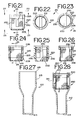
- FIGS. 21-28 A third embodiment of a combined filter element and calibration tube 200 is shown in FIGS. 21-28.
- the calibration tube 210 has a main body portion 215 that is used to totally contain the filter element 220.
- the frame of filter element 220 comprises longitudinal ribs 230 and a lateral rib 231 at the base.
- the proximal end 226 is completely open.
- the lateral rib 231 works with the distal end frame section 228 to hold filtration media 222 across the bottom. Fuel flow is thus in through the center open top and out through filtration media forming cylindrical side wall 223 or bottom 222. Flow can then enter the internal volume of the calibration tube 210 and flow out an opening 213 in the bottom thereof (see FIG. 28; showing flow arrows).
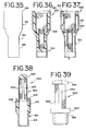
- FIG. 39 shows a sixth filtration element 520 that can be used with a calibration tube such as tube 60 that has a shoulder section 67 at its top.
- the flow is also radially inward through filtration media 522.
- the proximal end 526 and distal end 528 of the filter element 520 are connected by ribs 530.
- a shoulder 527 on distal end 528 is used to hold the filtration element 520 into a calibration tube so that the media 522 is exposed on the upstream side of the calibration tube.
Landscapes
- Engineering & Computer Science (AREA)
- Chemical & Material Sciences (AREA)
- Combustion & Propulsion (AREA)
- Mechanical Engineering (AREA)
- General Engineering & Computer Science (AREA)
- Physics & Mathematics (AREA)
- Electromagnetism (AREA)
- Fuel-Injection Apparatus (AREA)
- Filtration Of Liquid (AREA)
Abstract
Description
- The present application claims the benefit of the filing date under 35 U.S.C. § 119(e) of Provisional U.S. Patent Application Serial No. 60/323,750, filed September 19, 2001, which is hereby incorporated by reference in its entirety.
- The present invention relates to filters for fuel injectors, and particularly to such fuel filters integrated with a calibration tube.
- A fuel injector is used to inject fuel into a cylinder of an internal combustion engine. Typical a fuel filter is included inside the flow channel within the fuel injector to prevent any contaminants in the fuel from interfering with the operation of the fuel injector orifice. An example of such a filter is disclosed in U.S. Patent No. 4,608,166, which is hereby incorporated by reference. This filter, shown in FIGS. 1-3 herein, was itself an improvement over earlier filters in that it includes a
metal collar 26 that allowed thefilter 10 to be press fit into the fuel injector flow channel and to stay in place as the fuel injector heated and expanded with use. Themetal collar 26 was unique in that its leadingedge 22 was embedded in thermoplastic material used to construct the filter, so that as the filter was press fit into place, a smoothrounded corner 24 contacted the internal wall of the flow channel. This prevented any shearing of particles from the wall of the flow channel, generating debris that would have been downstream of the filter. - While this was a significant improvement over the prior art, there has still been a potential source of particles with the use of such filters. Inside of the flow channel there is also a spring and a calibration tube. These are used to adjust the flow rate of fuel injected by the fuel injector. Often the filter element rested on the proximal end of the calibration tube. As a result, there is the potential for abrasion between the calibration tube and the filter, resulting in debris downstream of the filter that can clog the fuel injector or otherwise adversely affect engine performance.
- There would be a great benefit if this source of potential particles could be eliminated. Also, it would be a benefit if the number of components used to construct a fuel injector were reduced, while maintaining a sufficient filtration capacity surface area.
- An integrated fuel filter and calibration tube has been invented which eliminates the potential for release of particles from the filter element by abrasion with the calibration tube. In preferred embodiments the filter is contained within the calibration tube, yet still has at least 60 mm2 of effective filtration surface area.
- In a first aspect, the invention is an integrated fuel filter and calibration tube for a fuel injector comprising a filtration element made from filtration media insert-molded into a thermoplastic frame member; and a calibration tube rigidly attached to the filtration element, the calibration tube being sized so as to fit inside of a fuel injector flow channel.
- In a second aspect, the invention is an integrated fuel filter and calibration tube for a fuel injector comprising an elongated outside metal housing having a body with an inside diameter and an outside diameter, a neck at the distal end of the housing smaller in outside diameter than the outside diameter of the body and a shoulder at the proximal end of the housing larger in inside diameter than the inside diameter of the body; and an injection-molded filter element inside the housing, the filter element comprising filtration media insert-molded into a frame, the frame comprising a proximal end having an outside diameter in between the inside diameters of the housing shoulder and the housing body, a distal end and a plurality of rib members joining the proximal end to the distal end, the frame holding the filtration media in a generally cylindrical shape.
- In a third aspect, the invention is a combination of a fuel injector and an integrated fuel filter and calibration tube comprising a fuel injector having a fuel flow channel therethrough and a spring inside the flow channel; and an integrated fuel filter and calibration tube inside the flow channel, the calibration tube contacting the spring, the fuel filter comprising a thermoplastic frame attached to the calibration tube, the frame having a proximal end, a distal end and at least one rib connecting the ends, the frame supporting filtration media to provide filtration of all fuel flowing through the fuel flow channel.
- The integrated fuel filter and calibration tube may be inserted into a fuel injector as a unit, thus eliminating the possibility of particles being generated from abrasion between the filter and the calibration tube, as well as reducing the number of individual parts needed for the assembly of the fuel injector. The preferred embodiment includes a filter element that is easy to manufacture and assemble.
- These and other advantages, as well as the invention itself, will be best understood in view of the attached drawings, a brief description of which follows:
-
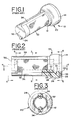
- FIGS. 1-3 are perspective and cross-sectional views of a prior art fuel injector filter.
- FIG. 4 is a cross-sectional view of a combination of a fuel injector and an integrated fuel filter and calibration tube of a first embodiment of the present invention.
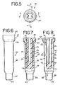
- FIG. 5 is an end view of the integrated fuel filter and calibration tube taken along line 5-5 of FIG. 4.
- FIG 6 is a cross-sectional view of the calibration tube used in the integrated fuel filter and calibration tube of FIG. 5.
- FIGS. 7 and 8 are cross-sectional views taken along lines 7-7 and 8-8, respectively, of FIG. 5.
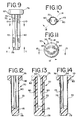
- FIG. 9 is a side view of the filter element used in the integrated fuel filter and calibration tube of FIGS. 4-5.
- FIG. 10 is a cross-sectional view taken along line 10-10 of FIG. 9.
- FIG. 11 is an end view taken along line 11-11 of FIG. 9.
- FIGS. 12, 13 and 14 are cross-sectional views taken along lines 12-12, 13-13 and 14-14, respectively, of FIGS. 10 and 11.
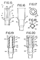
- FIG. 15 is a side elevational view of a fuel filter used in making a second embodiment of the integrated fuel filter and calibration tube of the present invention.
- FIG. 16 is a cross-sectional view of the calibration tube used in the second embodiment of the invention.
- FIG. 17 is an end view taken along line 17-17 of FIG. 15.
- FIG. 18 is a cross-sectional view taken along line 18-18 of FIG. 15.
- FIGS. 19 and 20 are cross-sectional views of the integrated fuel filter and calibration tube of FIGS. 15 and 16.
- FIG. 21 is a side elevational view of a fuel filter used in a third embodiment of an integrated fuel filter and calibration tube of the present invention.
- FIGS. 22 and 23 are end views taken along lines 22-22 and 23-23, respectively, of FIG. 21.
- FIGS. 24, 25 and 26 are cross-sectional views taken along lines 24-24, 25-25 and 26-26, respectively, of FIGS. 21, 24 and 23.
- FIG. 27 is a cross-sectional view of a calibration tube used with the fuel filter of FIG. 21 in making the third embodiment of the invention.
- FIG. 28 is a cross-sectional view of the integrated fuel filter and calibration tube of FIGS. 21 and 27.
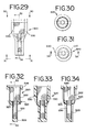
- FIG. 29 is a side elevational view of a fuel filter used in a fourth embodiment of an integrated fuel filter and calibration tube of the present invention.
- FIGS 30 and 31 are end views taken along lines 30-30 and 31-31, respectively, of FIG. 29.
- FIGS 32, 33 and 34 are cross-sectional views taken along lines 32-32, 33-33 and 34-34, respectively, of FIGS. 29, 32 and 31.
- FIG. 35 is a side elevational view of a calibration tube used with the fuel filter of FIG. 29 in making the fourth embodiment of the invention.
- FIGS. 36 and 37 are cross-sectional views of the integrated fuel filter and calibration tube of FIGS. 29 and 35.
- FIG. 38 is a side elevational view of a fifth embodiment of an integrated fuel filter and calibration tube of the present invention.
- FIG. 39 is a side elevational view of a filter element used to make an integrated fuel filter and calibration tube of a sixth embodiment of the present invention.
-
- The preferred embodiment of an integrated fuel filter and
calibration tube 60 of the present invention is shown in combination with other components of afuel injector 40 in FIG. 4. The integrated fuel filter andcalibration tube 60 is shown in FIGS. 5, 7 and 8. Its components include a housing orcalibration tube 62, best seen in FIG. 6, and afilter element 70 best seen if FIGS. 9-14. - The
fuel injector 40 has afuel flow channel 41 therethrough. Theflow channel 41 has alower portion 42 and anupper portion 44. Aspring 46 is inside theflow channel 41. The internal diameter of thelower portion 42 is less than the internal diameter of theupper portion 44. Thespring 46 rests on theshoulder 47 formed in the flow channel where the internal diameter changes. Other components of thefuel injector 40, such asball 48, are conventional and therefore not further described. Theupper portion 44 of the flow channel may have different internal diameters, as shown in FIG. 4, used to accommodate the integrated fuel filter andcalibration tube 60, which also fits within theflow channel 41. Thecalibration tube 62 contacts thespring 46 and is sized so as to fit inside theflow channel 41. - As best seen in FIGS. 5-14, the integrated fuel filter and
calibration tube 60 has two major components, the calibration tube orhousing 62 and thefilter element 70. Thecalibration tube 62 is preferably an elongated, drawn, stainless steel tube. Although other metals could be used, stainless steel has the advantage of not reacting with components used in the wide variety of fuels that may be fed throughinjector 40. Themetal tube 62 is rigidly attached to thefiltration element 70 after both pieces are first produced independently. Thetube 62 forms an elongated outside housing for thepreferred filter element 70. Thetube 62 has amain body portion 65, aneck 66 at the distal end of the housing and ashoulder 67 at the proximal end of the housing. Theneck 66 is smaller in outside diameter than the outside diameter of thebody 65. Theshoulder 67 has an internal diameter larger than that of thebody 65. Thisshoulder 67 is sized on its outside diameter so that the combined fuel filter andcalibration tube 60 may be press fit into the upper portion of thefuel flow channel 41. Thejuncture 68 of the housing between thebody 65 and theshoulder 67 forms an internal ledge. As shown in FIGS. 7 and 8, theproximal edge 69 of thehousing shoulder 67 is crimped over, preferably by rolling process, to hold aproximal end 76 of thefilter element 70 against theledge 68. - The fuel filter portion of the preferred integrated fuel filter and
calibration tube 60 is preferably an injection-molded filter element inside thehousing 62 made up offiltration media 72 insert molded into athermoplastic frame member 75. Themedia 72 is preferably a woven nylon screen, held in a generally cylindrical shape by theframe member 75. - The
frame member 75 comprises aproximal end 76, adistal end 78 and at least one, and preferably two,rib members 80 joining theproximal end 76 to the distal 78. The tworibs 80 are spaced at 180° from each other around the perimeter of the filtration media cylinder. Theproximal end 76 includes ashoulder 82 and a fuel inlet opening 84 along its axial center. Theshoulder 82 is used to secure thefiltration element 70 to thecalibration tube 62. In the embodiment shown in FIGS. 4-14, the outside diameter of theshoulder 82 of the proximal end of the filtration element is just smaller than the inside diameter of theshoulder section 67 of thecalibration tube 62 but larger than the inside diameter of thehousing body 65. Also, in the first embodiment, thefiltration element 70 is totally contained within thecalibration tube 62. However, even fitting inside this small area, the preferred design still is made with an effective filtration surface area of at least 60 mm2. The flow path of fuel through the filtration element is radially outward, as fuel enters through inlet opening 84 and is filtered as it passes outwardly through thefiltration media 72 as shown by flow arrows in FIG. 8. The fuel then passes into thespace 86 between thefilter element 70 and thecalibration tube 62, and flows out theopening 63 at the distal end of thecalibration tube 62. The preferred frame material is a 35% glass filled 6-12 nylon. Thepreferred media 72 is a 30 micron woven nylon screen. - By replacing the separate fuel filter and calibration tube, the wear surface between the calibration tube and filter is eliminated. The preferred parts are easily manipulated by automatic handling equipment. The stainless steel has minimal, if any, chemical and electrolyte reaction at the interfaces between the fuel filter and other components of the fuel injector.
- Other embodiments of the invention have many of the same benefits. The embodiment of FIGS. 15-20 is also an integrated fuel filter and
calibration tube 100. Again, thetube 110 is preferably made from stainless steel, and has abody portion 115 and anupper section 117. In this embodiment, thefilter element 120 is designed with a flow path of fuel through the filtration element radially inward. Fuel thus enters throughmedia 122 held open byribs 130 connecting theproximal end 126 and thebase 128 of the filter frame. The flow then passes out anopening 134 in thebase 128 of thefilter element 120. Thebase 128 includes ashoulder 132 that is secured inside theupper section 117 of thecalibration tube 110. The two pieces are held together by crimping in acenter section 119 of thetube 110 to clamp over theshoulder 132 of the frame of the filter element 120 (FIGS. 19 and 20). - A third embodiment of a combined filter element and
calibration tube 200 is shown in FIGS. 21-28. Thecalibration tube 210 has amain body portion 215 that is used to totally contain thefilter element 220. The frame offilter element 220 compriseslongitudinal ribs 230 and alateral rib 231 at the base. Theproximal end 226 is completely open. However, thelateral rib 231 works with the distalend frame section 228 to holdfiltration media 222 across the bottom. Fuel flow is thus in through the center open top and out through filtration media formingcylindrical side wall 223 orbottom 222. Flow can then enter the internal volume of thecalibration tube 210 and flow out anopening 213 in the bottom thereof (see FIG. 28; showing flow arrows). This filter thus has a generally radially outward filtration path, but also part of the filtration flow path is axially downward. Again, theproximal edge 219 of the housing is crimped over to secure thefilter element 220 inside tube 210 (FIG. 28). - A
fourth embodiment 300 is shown in FIGS. 29-37. Thecalibration tube 310 includes amain body portion 315 and a smallerdiameter neck portion 316. However, in this embodiment, to increase the effective filtration surface area, thefilter element 320 has two sections. The bottom section fits intoneck portion 316 oftube 310, and the top section fits intomain body portion 315. The filtration media is formed into two cylindrical portions,top portion 322 andbottom portion 323. The bottom oftop portion 322 and the top ofbottom portion 323 are captured by insert injection molding in the plastic used to formcenter member 325 of the frame offiltration element 320.Center section 325 has ahole 327 in its center so that fuel in the top cylinder can supply the bottom cylinder offiltration media 323. In this embodiment, flow through the filtration media is generally radially outward, as shown by flow across in FIG. 37. - The
proximal end 326 anddistal end 328, as well ascenter section 325, of the frame member are held in a spaced relationship by tworibs 330 that run the entire length of thefilter element 320. Again, theproximal edge 319 oftube 310 is crimped over to hold theproximal end 326 offilter element 320 inside the housing of calibration tube 310 (FIGS. 36 and 37), integrating the two pieces. - FIG. 38 shows a fifth integrated fuel element and
calibration tube 400. Thecalibration tube 410 has aneck portion 416 and a largermain body portion 415. Thefuel filter 420 has adistal end 428 that fits into themain body 415. Theproximal end 419 of thetube 410 is crimped over to secure the two pieces together.Ribs 430 and aproximal end 426 of the frame hold thefiltration media 422 into a generally cylindrical shape. The flow path is radially inward through the filtration media and thefilter element 420 extends upstream of thecalibration tube 410. - FIG. 39 shows a
sixth filtration element 520 that can be used with a calibration tube such astube 60 that has ashoulder section 67 at its top. In this embodiment, the flow is also radially inward throughfiltration media 522. Theproximal end 526 anddistal end 528 of thefilter element 520 are connected byribs 530. Ashoulder 527 ondistal end 528 is used to hold thefiltration element 520 into a calibration tube so that themedia 522 is exposed on the upstream side of the calibration tube. - By using the present invention, a single integrated fuel filter and calibration tube can be used to construct fuel injectors, simplifying assembly. The chance for particles being generated downstream of the filter by contact between the filter and the calibration tube is eliminated. The preferred embodiments are capable of mass manufacture using insert injection-molding techniques. Those embodiments that have outward-flow filtration are preferred because the media would not collapse if it became partially plugged.
- It should be appreciated that the apparatus of the present invention is capable of being incorporated in the form of a variety of embodiments, only a few of which have been illustrated and described above. The invention may be embodied in other forms without departing from its spirit or essential characteristics. For example, instead of being made of stainless steel, the various calibration tubes could be made from bronze, brass or other materials, even polymers, if they could maintain a press-fit into the flow channel of the fuel injector. The frame of the filter element could be made of any material that would stand up to the fuel. Other filtration medias could be used. The described embodiments are to be considered in all respects only as illustrative and not restrictive, and the scope of the invention is, therefore, indicated by the appended claims rather than by the foregoing description. All changes that come within the meaning and range of equivalency of the claims are to be embraced within their scope.
Claims (20)
- An integrated fuel filter and calibration tube for a fuel injector comprising:a) a filtration element comprising filtration media insert-molded into a thermoplastic frame member; andb) a calibration tube rigidly attached to the filtration element, the calibration tube being sized so as to fit inside of a fuel injector flow channel.
- The integrated fuel filter and calibration tube of claim 1 wherein the frame member comprises a proximal end, a distal end and at least one rib connecting the ends.
- The integrated fuel filter and calibration tube of claim 1 wherein the proximal end comprises a fuel inlet opening.
- The integrated fuel filter and calibration tube of claim 1 wherein the filtration media is held in a generally cylindrical shape by said frame member.
- The integrated fuel filter and calibration tube of claim 4 wherein a flow path of fuel through the filtration media is generally radially outward.
- The integrated fuel filter and calibration tube of claim 4 wherein a flow path of fuel through the filtration media is generally radially inward.
- The integrated fuel filter and calibration tube of claim 1 wherein the filtration element is totally contained within the calibration tube.
- The integrated fuel filter and calibration tube of claim 1 wherein the filtration element extends upstream from the calibration tube.
- The integrated fuel filter and calibration tube of claim 1 wherein the filtration media comprises a woven nylon screen.
- The integrated fuel filter and calibration tube of claim 1 wherein the frame member includes a shoulder used to secure the filtration element to the calibration tube.
- An integrated fuel filter and calibration tube for a fuel injector comprising:a) an elongated outside metal housing having a body with an inside diameter and an outside diameter, a neck at a distal end of the housing smaller in outside diameter than the outside diameter of the body and a shoulder at a proximal end of the housing larger in inside diameter than the inside diameter of the body; andb) an injection-molded filter element inside the housing, the filter element comprising filtration media insert-molded into a frame, the frame comprising a proximal end having an outside diameter in between the inside diameters of the housing shoulder and the housing body, a distal end and a plurality of rib members joining the proximal end to the distal end, the frame holding the filtration media in a generally cylindrical shape.
- The integrated fuel filter and calibration tube of claim 1 wherein a proximal edge of the housing shoulder is crimped over to hold a proximal end of the filter element frame against a juncture of the housing between the body and the shoulder
- The integrated fuel filter and calibration tube of claim 11 having an effective filtration surface area of at least 60 mm2
- The integrated fuel filter and calibration tube of claim 11 wherein the housing is made of stainless steel.
- The integrated fuel filter and calibration tube of claim 11 wherein a proximal end of the frame comprises an inlet opening wherein fuel enters the filter element along its axial center and is filtered by flowing generally radially outward through the filtration media.
- The integrated fuel filter and calibration tube of claim 11 wherein the frame comprises two ribs spaced at 180° from each other around the perimeter of the filtration media cylinder.
- A combination of a fuel injector and an integrated fuel filter and calibration tube comprising:a) a fuel injector having a fuel flow channel therethrough and a spring inside said flow channel; andb) an integrated fuel filter and calibration tube inside said flow channel, said calibration tube contacting said spring, said fuel filter comprising a thermoplastic frame attached to said calibration tube, the frame having a proximal end, a distal end and at least one rib connecting the ends, the frame supporting filtration media to provide filtration of all fuel flowing through the fuel flow channel.
- The combination of claim 17 wherein the flow channel has an upper portion with a first internal diameter and a lower portion with a second internal diameter smaller than the first internal diameter and the calibration tube has a shoulder on its proximal end press fit into the upper portion of the fuel flow channel.
- The combination of claim 17 wherein the filter is totally contained within the calibration tube and has an effective filtration surface area of at least 60 mm2.
- The combination of claim 17 wherein the frame member includes a shoulder and an inlet opening at its proximal end, and the shoulder is held into a mating shoulder of the calibration tube by roll crimping the proximal edge of the calibration tube over the frame member shoulder.
Applications Claiming Priority (2)
| Application Number | Priority Date | Filing Date | Title |
|---|---|---|---|
| US32375001P | 2001-09-19 | 2001-09-19 | |
| US323750P | 2001-09-19 |
Publications (2)
| Publication Number | Publication Date |
|---|---|
| EP1296057A1 true EP1296057A1 (en) | 2003-03-26 |
| EP1296057B1 EP1296057B1 (en) | 2011-01-05 |
Family
ID=23260543
Family Applications (1)
| Application Number | Title | Priority Date | Filing Date |
|---|---|---|---|
| EP02256468A Expired - Lifetime EP1296057B1 (en) | 2001-09-19 | 2002-09-18 | Integrated fuel filter and calibration tube for a fuel injector |
Country Status (5)
| Country | Link |
|---|---|
| US (1) | US20030052052A1 (en) |
| EP (1) | EP1296057B1 (en) |
| BR (1) | BR0203833B1 (en) |
| CA (1) | CA2404247C (en) |
| DE (1) | DE60238813D1 (en) |
Cited By (5)
| Publication number | Priority date | Publication date | Assignee | Title |
|---|---|---|---|---|
| EP1806497A1 (en) | 2006-01-10 | 2007-07-11 | Siemens Aktiengesellschaft | Injector |
| WO2009053219A1 (en) * | 2007-10-18 | 2009-04-30 | Robert Bosch Gmbh | Fuel injection valve |
| EP2426351A1 (en) * | 2010-09-02 | 2012-03-07 | Continental Automotive GmbH | Adjusting fuel filter assembly and injection valve |
| EP2549094A2 (en) | 2011-07-18 | 2013-01-23 | Robert Bosch Gmbh | An injection valve for internal combustion engines |
| EP3080434A1 (en) * | 2013-12-13 | 2016-10-19 | Robert Bosch GmbH | Fuel injection valve |
Families Citing this family (35)
| Publication number | Priority date | Publication date | Assignee | Title |
|---|---|---|---|---|
| US6766825B2 (en) * | 2002-08-02 | 2004-07-27 | Bruce A. Antunez | Top-loaded replaceable flow control and particulate strainer |
| DE502005004986D1 (en) * | 2004-07-29 | 2008-09-25 | Schaeffler Kg | ring filter |
| EP1783360B1 (en) * | 2005-11-02 | 2008-03-26 | Delphi Technologies, Inc. | Internal filter for a fuel injector |
| US7617991B2 (en) * | 2006-03-31 | 2009-11-17 | Delphi Technologies, Inc. | Injector fuel filter with built-in orifice for flow restriction |
| JP2008194587A (en) * | 2007-02-09 | 2008-08-28 | Toyo Roki Mfg Co Ltd | Filtration filter and manufacturing method thereof |
| DE102013225829A1 (en) | 2013-12-13 | 2015-06-18 | Robert Bosch Gmbh | Fuel injector |
| DE102013225817A1 (en) | 2013-12-13 | 2015-06-18 | Robert Bosch Gmbh | Fuel injector |
| DE102013225812A1 (en) | 2013-12-13 | 2015-06-18 | Robert Bosch Gmbh | Fuel injector |
| DE102013225820A1 (en) | 2013-12-13 | 2015-06-18 | Robert Bosch Gmbh | Fuel injector |
| DE102013225840A1 (en) | 2013-12-13 | 2015-06-18 | Robert Bosch Gmbh | Fuel injector |
| EP2896816A1 (en) * | 2014-01-16 | 2015-07-22 | Continental Automotive GmbH | Filter assembly for a fuel injector, fuel injector and method for assembly the filter assembly |
| EP2910770B1 (en) * | 2014-02-20 | 2018-09-19 | Continental Automotive GmbH | Filter assembly and fuel injector |
| DE102014226003A1 (en) | 2014-12-16 | 2016-06-16 | Robert Bosch Gmbh | Fuel injector |
| DE102014225994A1 (en) | 2014-12-16 | 2016-06-16 | Robert Bosch Gmbh | Fuel injector |
| DE102014225999A1 (en) | 2014-12-16 | 2016-06-16 | Robert Bosch Gmbh | Fuel injector |
| FR3038938B1 (en) * | 2015-07-17 | 2018-12-07 | Delphi Technologies Ip Limited | HIGH PRESSURE FILTER FOR FUEL INJECTOR |
| DE102015226515A1 (en) | 2015-12-22 | 2017-06-22 | Robert Bosch Gmbh | Fuel injector |
| DE102015226528A1 (en) | 2015-12-22 | 2017-06-22 | Robert Bosch Gmbh | Fuel injector |
| DE102015226533A1 (en) | 2015-12-22 | 2017-06-22 | Robert Bosch Gmbh | Fuel injector |
| DE102015226541A1 (en) | 2015-12-22 | 2017-06-22 | Robert Bosch Gmbh | Fuel injector |
| DE102016226135A1 (en) * | 2016-12-23 | 2018-06-28 | Robert Bosch Gmbh | Fuel injector |
| DE102016226142A1 (en) | 2016-12-23 | 2018-06-28 | Robert Bosch Gmbh | Fuel injector |
| JP6767293B2 (en) * | 2017-03-23 | 2020-10-14 | 株式会社ニフコ | Filter device |
| JP6782668B2 (en) * | 2017-06-16 | 2020-11-11 | 日立オートモティブシステムズ株式会社 | Fuel injection valve |
| US10859051B2 (en) | 2018-06-12 | 2020-12-08 | Delphi Technologies Ip Limited | Fuel injector with combined calibration tube, fuel filter, and pressure pulsation damping orifice |
| CN112867862B (en) * | 2018-10-02 | 2023-08-04 | 纬湃科技有限责任公司 | Adjusting filter for fluid injection valve and fluid injection valve |
| US20220136473A1 (en) * | 2020-10-30 | 2022-05-05 | Caterpillar Inc. | Filtration device for a common rail fuel injector |
| DE102020214154A1 (en) | 2020-11-11 | 2022-05-12 | Robert Bosch Gesellschaft mit beschränkter Haftung | fuel injector |
| US11852112B2 (en) * | 2020-11-24 | 2023-12-26 | Caterpillar Inc. | Fuel injector with internal filter element |
| DE102020215215A1 (en) | 2020-12-02 | 2022-06-02 | Robert Bosch Gesellschaft mit beschränkter Haftung | fuel injector |
| DE102020215218A1 (en) | 2020-12-02 | 2022-06-02 | Robert Bosch Gesellschaft mit beschränkter Haftung | fuel injector |
| DE102020215217A1 (en) | 2020-12-02 | 2022-06-02 | Robert Bosch Gesellschaft mit beschränkter Haftung | fuel injector |
| DE102020215621A1 (en) | 2020-12-10 | 2022-06-15 | Robert Bosch Gesellschaft mit beschränkter Haftung | fuel injector |
| DE102020215794A1 (en) | 2020-12-14 | 2022-06-15 | Robert Bosch Gesellschaft mit beschränkter Haftung | fuel injector |
| DE102022210875A1 (en) | 2022-10-14 | 2024-04-25 | Robert Bosch Gesellschaft mit beschränkter Haftung | Fuel injector |
Citations (5)
| Publication number | Priority date | Publication date | Assignee | Title |
|---|---|---|---|---|
| US4608166A (en) | 1985-04-01 | 1986-08-26 | Filtertek, Inc. | Press fit filter |
| US5340032A (en) * | 1991-09-21 | 1994-08-23 | Robert Bosch Gmbh | Electromagnetically operated injection valve with a fuel filter that sets a spring force |
| US5921475A (en) * | 1997-08-07 | 1999-07-13 | Ford Motor Company | Automotive fuel injector |
| DE10102381A1 (en) * | 2000-01-19 | 2001-08-02 | Delphi Tech Inc | Spring force calibration tube for a fuel injector with an internally attached fuel inlet filter |
| EP1229239A2 (en) * | 2001-02-02 | 2002-08-07 | Siemens VDO Automotive Corporation | Combined filter and adjuster for a fuel injector |
Family Cites Families (5)
| Publication number | Priority date | Publication date | Assignee | Title |
|---|---|---|---|---|
| US4130622A (en) * | 1977-02-22 | 1978-12-19 | Abbott Laboratories | Method of making self-supporting tubular filter |
| US5252204A (en) * | 1992-08-20 | 1993-10-12 | Manufacturers Components, Inc. | Unimold filter |
| DE19647587A1 (en) * | 1996-11-18 | 1998-05-20 | Bosch Gmbh Robert | Fuel injector |
| US6199775B1 (en) * | 2000-02-23 | 2001-03-13 | Siemens Automotive Corporation | Fuel injector filter unit having a composite housing |
| US6698664B2 (en) * | 2000-12-29 | 2004-03-02 | Siemens Automotive Corporation | Modular fuel injector having an integral or interchangeable inlet tube and having an integral filter and dynamic adjustment assembly |
-
2002
- 2002-09-18 EP EP02256468A patent/EP1296057B1/en not_active Expired - Lifetime
- 2002-09-18 CA CA002404247A patent/CA2404247C/en not_active Expired - Fee Related
- 2002-09-18 DE DE60238813T patent/DE60238813D1/en not_active Expired - Lifetime
- 2002-09-19 US US10/251,704 patent/US20030052052A1/en not_active Abandoned
- 2002-09-19 BR BRPI0203833-1A patent/BR0203833B1/en not_active IP Right Cessation
Patent Citations (5)
| Publication number | Priority date | Publication date | Assignee | Title |
|---|---|---|---|---|
| US4608166A (en) | 1985-04-01 | 1986-08-26 | Filtertek, Inc. | Press fit filter |
| US5340032A (en) * | 1991-09-21 | 1994-08-23 | Robert Bosch Gmbh | Electromagnetically operated injection valve with a fuel filter that sets a spring force |
| US5921475A (en) * | 1997-08-07 | 1999-07-13 | Ford Motor Company | Automotive fuel injector |
| DE10102381A1 (en) * | 2000-01-19 | 2001-08-02 | Delphi Tech Inc | Spring force calibration tube for a fuel injector with an internally attached fuel inlet filter |
| EP1229239A2 (en) * | 2001-02-02 | 2002-08-07 | Siemens VDO Automotive Corporation | Combined filter and adjuster for a fuel injector |
Cited By (5)
| Publication number | Priority date | Publication date | Assignee | Title |
|---|---|---|---|---|
| EP1806497A1 (en) | 2006-01-10 | 2007-07-11 | Siemens Aktiengesellschaft | Injector |
| WO2009053219A1 (en) * | 2007-10-18 | 2009-04-30 | Robert Bosch Gmbh | Fuel injection valve |
| EP2426351A1 (en) * | 2010-09-02 | 2012-03-07 | Continental Automotive GmbH | Adjusting fuel filter assembly and injection valve |
| EP2549094A2 (en) | 2011-07-18 | 2013-01-23 | Robert Bosch Gmbh | An injection valve for internal combustion engines |
| EP3080434A1 (en) * | 2013-12-13 | 2016-10-19 | Robert Bosch GmbH | Fuel injection valve |
Also Published As
| Publication number | Publication date |
|---|---|
| CA2404247A1 (en) | 2003-03-19 |
| DE60238813D1 (en) | 2011-02-17 |
| CA2404247C (en) | 2006-06-20 |
| EP1296057B1 (en) | 2011-01-05 |
| US20030052052A1 (en) | 2003-03-20 |
| BR0203833A (en) | 2003-06-03 |
| BR0203833B1 (en) | 2010-12-14 |
Similar Documents
| Publication | Publication Date | Title |
|---|---|---|
| EP1296057B1 (en) | Integrated fuel filter and calibration tube for a fuel injector | |
| US5335863A (en) | Filter cartridge mounting for a top-feed fuel injector | |
| EP0755485B1 (en) | Discrete filter mounted in fuel rail | |
| CN102325986B (en) | Water separator, in particular for fuel supply systems of internal combustion engines in motor vehicles | |
| JPH06502902A (en) | Electromagnetic actuated injection valve | |
| US20100206800A1 (en) | Water separator, in particular for fuel supply systems of internal combustion engines in motor vehicles | |
| US6846412B2 (en) | Combination filter assembly | |
| US20090199822A1 (en) | Fuel delivery system for heating fuel therein | |
| US7191767B2 (en) | Reservoir assembly having interchangeable fuel suction unit and fuel pump assembly for vehicles | |
| EP1921303B1 (en) | Fuel pump and filter assembly | |
| US20110192786A1 (en) | Fuel filter | |
| TWI257450B (en) | Fuel supply device | |
| US20100213286A1 (en) | Adjusting and filter arrangement for an injection valve and injection valve | |
| JPH05504182A (en) | solenoid operated valve | |
| JPS585464A (en) | Injection valve | |
| KR20000005687A (en) | Filter for fuel | |
| US6446885B1 (en) | Secondary filter assembly for fuel injector | |
| KR102468478B1 (en) | Filter for fluid having at least one heating apparatus and method for manufacturing same | |
| US6098652A (en) | Quick connect fuel filter and regulator | |
| EP1415081A1 (en) | Fuel transporting device for a motor vehicle | |
| US6997404B2 (en) | Porous plastic fuel filter for a fuel injector | |
| JP2824761B2 (en) | Filter in fuel injection valve | |
| US20080072554A1 (en) | Filter Apparatus Especially for Filtration of Combustion Air in Internal Combustion Engines | |
| US7407057B2 (en) | Plastic transmission filter | |
| JP2009174423A (en) | Fuel injection valve |
Legal Events
| Date | Code | Title | Description |
|---|---|---|---|
| PUAI | Public reference made under article 153(3) epc to a published international application that has entered the european phase |
Free format text: ORIGINAL CODE: 0009012 |
|
| AK | Designated contracting states |
Kind code of ref document: A1 Designated state(s): AT BE BG CH CY CZ DE DK EE ES FI FR GB GR IE IT LI LU MC NL PT SE SK TR Designated state(s): AT BE BG CH CY CZ DE DK EE ES FI FR GB GR IE IT LI LU MC NL PT SE SK TR |
|
| AX | Request for extension of the european patent |
Extension state: AL LT LV MK RO SI |
|
| 17P | Request for examination filed |
Effective date: 20030828 |
|
| AKX | Designation fees paid |
Designated state(s): DE FR GB IE IT |
|
| RAP1 | Party data changed (applicant data changed or rights of an application transferred) |
Owner name: FILTERTEK INC. |
|
| 17Q | First examination report despatched |
Effective date: 20070801 |
|
| GRAP | Despatch of communication of intention to grant a patent |
Free format text: ORIGINAL CODE: EPIDOSNIGR1 |
|
| GRAS | Grant fee paid |
Free format text: ORIGINAL CODE: EPIDOSNIGR3 |
|
| GRAA | (expected) grant |
Free format text: ORIGINAL CODE: 0009210 |
|
| AK | Designated contracting states |
Kind code of ref document: B1 Designated state(s): DE FR GB IE IT |
|
| REG | Reference to a national code |
Ref country code: GB Ref legal event code: FG4D |
|
| REG | Reference to a national code |
Ref country code: IE Ref legal event code: FG4D |
|
| REF | Corresponds to: |
Ref document number: 60238813 Country of ref document: DE Date of ref document: 20110217 Kind code of ref document: P |
|
| REG | Reference to a national code |
Ref country code: DE Ref legal event code: R096 Ref document number: 60238813 Country of ref document: DE Effective date: 20110217 |
|
| PLBE | No opposition filed within time limit |
Free format text: ORIGINAL CODE: 0009261 |
|
| STAA | Information on the status of an ep patent application or granted ep patent |
Free format text: STATUS: NO OPPOSITION FILED WITHIN TIME LIMIT |
|
| 26N | No opposition filed |
Effective date: 20111006 |
|
| PG25 | Lapsed in a contracting state [announced via postgrant information from national office to epo] |
Ref country code: IT Free format text: LAPSE BECAUSE OF FAILURE TO SUBMIT A TRANSLATION OF THE DESCRIPTION OR TO PAY THE FEE WITHIN THE PRESCRIBED TIME-LIMIT Effective date: 20110105 |
|
| REG | Reference to a national code |
Ref country code: DE Ref legal event code: R097 Ref document number: 60238813 Country of ref document: DE Effective date: 20111006 |
|
| GBPC | Gb: european patent ceased through non-payment of renewal fee |
Effective date: 20110918 |
|
| REG | Reference to a national code |
Ref country code: IE Ref legal event code: MM4A |
|
| REG | Reference to a national code |
Ref country code: FR Ref legal event code: ST Effective date: 20120531 |
|
| REG | Reference to a national code |
Ref country code: DE Ref legal event code: R119 Ref document number: 60238813 Country of ref document: DE Effective date: 20120403 |
|
| PG25 | Lapsed in a contracting state [announced via postgrant information from national office to epo] |
Ref country code: IE Free format text: LAPSE BECAUSE OF NON-PAYMENT OF DUE FEES Effective date: 20110918 Ref country code: DE Free format text: LAPSE BECAUSE OF NON-PAYMENT OF DUE FEES Effective date: 20120403 |
|
| PG25 | Lapsed in a contracting state [announced via postgrant information from national office to epo] |
Ref country code: FR Free format text: LAPSE BECAUSE OF NON-PAYMENT OF DUE FEES Effective date: 20110930 Ref country code: GB Free format text: LAPSE BECAUSE OF NON-PAYMENT OF DUE FEES Effective date: 20110918 |