EP1295976A1 - Flat knitting machine for making tubular knitting - Google Patents
Flat knitting machine for making tubular knitting Download PDFInfo
- Publication number
- EP1295976A1 EP1295976A1 EP01810908A EP01810908A EP1295976A1 EP 1295976 A1 EP1295976 A1 EP 1295976A1 EP 01810908 A EP01810908 A EP 01810908A EP 01810908 A EP01810908 A EP 01810908A EP 1295976 A1 EP1295976 A1 EP 1295976A1
- Authority
- EP
- European Patent Office
- Prior art keywords
- knitting
- needles
- cams
- guide
- guide grooves
- Prior art date
- Legal status (The legal status is an assumption and is not a legal conclusion. Google has not performed a legal analysis and makes no representation as to the accuracy of the status listed.)
- Withdrawn
Links
Images


Classifications
-
- D—TEXTILES; PAPER
- D04—BRAIDING; LACE-MAKING; KNITTING; TRIMMINGS; NON-WOVEN FABRICS
- D04B—KNITTING
- D04B15/00—Details of, or auxiliary devices incorporated in, weft knitting machines, restricted to machines of this kind
- D04B15/94—Driving-gear not otherwise provided for
- D04B15/96—Driving-gear not otherwise provided for in flat-bed knitting machines
-
- D—TEXTILES; PAPER
- D04—BRAIDING; LACE-MAKING; KNITTING; TRIMMINGS; NON-WOVEN FABRICS
- D04B—KNITTING
- D04B15/00—Details of, or auxiliary devices incorporated in, weft knitting machines, restricted to machines of this kind
- D04B15/32—Cam systems or assemblies for operating knitting instruments
- D04B15/36—Cam systems or assemblies for operating knitting instruments for flat-bed knitting machines
- D04B15/362—Cam systems or assemblies for operating knitting instruments for flat-bed knitting machines with two needle beds in V-formation
-
- D—TEXTILES; PAPER
- D04—BRAIDING; LACE-MAKING; KNITTING; TRIMMINGS; NON-WOVEN FABRICS
- D04B—KNITTING
- D04B7/00—Flat-bed knitting machines with independently-movable needles
- D04B7/30—Flat-bed knitting machines with independently-movable needles specially adapted for knitting goods of particular configuration
- D04B7/32—Flat-bed knitting machines with independently-movable needles specially adapted for knitting goods of particular configuration tubular goods
Definitions
- the present invention relates to a knitting loom straight to form a seamless tubular knit comprising two needle beds provided with guide grooves knitting needles defining needle trajectories that the needles of a needle bed do not not cross those of the other bed, knitting cams to move said needles along said grooves, drive means so that the displacement said knitting cams engaged with said needles produce in one direction only on a needle and in the direction opposite on the other needle bed and means for passing the knitting yarn from the needles of a needle to those of the other needle bed.
- the object of the present invention is to increase the speed knitting compared to straight looms, too well the traditional trades than that described in EP 1 127 970 mentioned above.
- the subject of the present invention is a straight knitting loom to form a tubular knit seamless of the aforementioned type corresponding to claim 1.
- the knitting loom according to the invention no longer comprises of the carriage and the knitting cams do not pass more than one one to another.
- the moving masses are therefore very significantly reduced so that the speed can be significantly increased compared to the solution above, allowing to approach the speeds of the trades classic straight knitting yarns.
- the proposed solution is also simple to make and can also offer mesh adjustment possibilities equivalent to those classic trades.
- the knitting loom according to the present invention is a loom of the type described in EP 1 127 970 mentioned above which may be referred to, the present invention relating only to the actuation of the needle knitting from this craft.
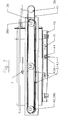
- the knitting loom illustrated in Figures 1-3 has two needle beds 1, 2, in which a plurality of parallel guide grooves 1a, respectively 2a are formed. Knitting needles 3 are slidably mounted in these guide grooves 1a, 2a. These needle beds 1, 2 form an angle between them, chosen so that their respective knitting needles 3 do not intersect not during their normal knitting runs.
- the knitting loom comprises a device comprising two plates 4, 5 held parallel to each other by spacers 6 fixed by screws 7.
- the plates 4 arranged adjacent in the beds 1, 2 have two rows of openings ovals 8a, 8b.
- the oval openings 8a 8b of the two rows are arranged longitudinally along each and are spread over the two rows so that the centers of the respective respective roundings of two openings 8a, 8b successive of the two rows lie on a line parallel to the guide grooves 1a, 2a of the needles 3 of respective beds 1, 2 ( Figure 2). Thanks to this arrangement, the rectilinear parts of these oval openings are succeed without end from one end to the other of the needle beds respective 1, 2 alternating from one row to another.
- Each oval opening 8a, 8b receives a guide core 9a, 9b which provides a closed loop guide slot 10a, 10b of equal width between the oval opening 8a, 8b and the respective guide core 9a, 9b.
- Each guide core 9a, 9b is positioned in the respective oval opening 8a, 8b by two positioning rods 11a, respectively 11b which are positioned and fixed in the parallel plate 5 by screws 12a, 12b.
- a double pinion 13a, 13a ', 13b, 13b' is pivotally mounted on one of the rods of each pair of positioning rods 11a, 11b integral with the same guide core 9a, 9b. Only a pinion 13a, respectively 13b is pivotally mounted on the other rod 11a, 11b secured to the same core of guide 9a, 9b.
- the two pinions 13a, and the two pinions 13b, integral with the same guide core 9a, respectively 9b are kinematically connected to each other by a endless belt 14a, 14b.
- the pinions 13a ', 13b' they are engaged with an endless belt 15 driven by a motor pinion 16, connected to the drive motor (not shown) of the knitting loom by a cardan shaft 17 and a bevel gear 18 engaged with a bevel gear 19 of a drive shaft 20 of the wire guides 21.
- these thread guides are integral with an endless belt 22 in taken with two pinions 23a, 23b, one of which 23a is coaxial and secured to a pinion 24 connected to a pinion 25 secured of the drive shaft 20 by an endless belt 26.
- the endless belts 14a, 14b are each engaged with one or more sliding supports 27a, 27b each comprising a sort of flange 27a 1 , 27b 1 ( Figures 4, 4b). These flanges 27a 1 , 27b 1 are engaged in guide grooves 28a, respectively 28b formed in the thickness of the edges of the oval openings 8a, 8b and of the guide cores 9a, 9b, delimiting closed loop guide slots 10a, 10b.
- the guide cores 9a, 9b are preferably made in two assembled parts 9a 1 , 9a 2 , respectively 9b 1 , 9b 2 , to allow the introduction of the flanges 27a 1 , 27b 1 of the sliding supports in the grooves guides 28a, 28b.
- Each sliding support 27a, 27b carries a pair of knitting cams ( Figures 5, 5b), an ascending cam in two parts 29 30 and a felling cam 51, intended for engaging the pushers 31a, 31b of the needles knitting 3.
- Each knitting cam 29, 30, 51 is integral a push rod 32, respectively 33.
- FIG. 6 illustrates the mechanism for moving the cams 29, 30 from one to the other of their positions.
- This mechanism has two symmetrical support arms 48 to which two levers 49 are articulated.
- Each of these levers 49 has a slot 49a in which a pegs 50a of a slide 50 can slide.
- Each slide 50 has a cam-shaped slot 50b, each being engaged with a pin 32a, respectively 33a of one of the push rods 32, 33.
- the levers 49 tilt in either of their positions (see Figure 6) and put the knitting cams 29, 30 on or off.
- each of these sliding supports 27a, 27b carries two guide rollers 42 (FIG. 4b) which press against a same edge of the slots 10a, 10b.
- the sliding supports 27a, 27b engaged with the endless belts 14a, 14b are driven according to trajectories defined by the slots 10a, 10b. Only one right part of the oval trajectory thus described by sliding supports 27a, 27b is used to actuate the needle pushers 31a, 31b. This right part is that in which the sliding supports 27a, 27b and so the knitting cams 29, 30, 51 which they carry move in the direction of the arrows F.
- the variant illustrated in Figure 7 does not differ from that illustrated in Figures 1-6 only by the fact that at instead of having two rows of oval loops 8a, 8b on which run the sliding supports 27a, 27b carrying knitting cams 29, 30, 51 this variant does not include that a single belt 36 making the entire length of the bed and guided by pulleys 38a, 38b.
- training knitting cam supports 37 integral with the belt endless 36 is obtained by a drive pulley 39 connected to a pinion 40 coaxial to pinion 38b by a drive belt 41.
- the knitting cams 37 move along the entire length of the knitting loom in the direction of arrow F on the upper end of the endless belt 36 where they selectively engage the pushers knitting needles 3 and come back in the opposite direction along the lower strand of this belt 36 where the stops can move the cams according to the needles selected, as previously described in relation to the first form of execution.
- FIG. 7 also shows a mechanism for adjusting the length of the meshes which applies both to this variant and to the previous embodiment.
- Each needle bed 1, 2 is secured to arms 43 each of which carries a pin 43a which projects on one of its faces to engage in a slot-shaped cam 44 formed in an adjustment member 45 slidably mounted on the frame (not shown) of the knitting loom, in the direction of the double arrow F 1 .
- the cams 44 in the form of slots make it possible to move the needle beds 1, 2 parallel to the knitting needles 3, so that the relative position between the knitting needles 3 and the felling plates 46 ( Figure 3) and therefore the length of the mesh.
- the knitting loom according to the invention offers all the knitting possibilities of a conventional loom with regard to concerns the selection of needles and the adjustment of lengths of meshes.
- the mass of the sliding supports 27a, 27b has nothing comparable to that of a conventional cart, this which allows a significant increase in the knitting speed.
Abstract
Description
La présente invention se rapporte à un métier à tricoter rectiligne pour former un tricot tubulaire sans couture comportant deux fontures munies de rainures de guidage des aiguilles de tricotage définissant des trajectoires d'aiguilles selon lesquelles les aiguilles d'une fontures ne croisent pas celles de l'autre fonture, des cames de tricotage pour déplacer lesdites aiguilles le long desdites rainures, des moyens d'entraínement pour que le déplacement dites cames de tricotage en prise avec lesdites aiguilles se produise dans un seul sens sur une fonture et dans le sens opposé sur l'autre fonture et des moyens pour faire passer le fil à tricoter des aiguilles d'une fonture à celles de l'autre fonture.The present invention relates to a knitting loom straight to form a seamless tubular knit comprising two needle beds provided with guide grooves knitting needles defining needle trajectories that the needles of a needle bed do not not cross those of the other bed, knitting cams to move said needles along said grooves, drive means so that the displacement said knitting cams engaged with said needles produce in one direction only on a needle and in the direction opposite on the other needle bed and means for passing the knitting yarn from the needles of a needle to those of the other needle bed.
On a déjà proposé un tel métier à tricoter qui est
décrit dans le EP 1 127 970 auquel on pourra se référer
quant aux particularités qui ne concernent pas directement
la présente invention. Pour obtenir un tricot tubulaire sans
couture, il est nécessaire de faire tourner les chariots
porteurs des cames d'actionnement des aiguilles toujours
dans le même sens, faisant ainsi passer alternativement ces
chariots d'une fonture à l'autre en les faisant tourner
lorsqu'ils arrivent à l'extrémité de chaque fonture. En variante,
les chariots tourneht dans un plan presque vertical,
vis-à-vis du même lit d'aiguilles.We have already proposed such a knitting machine which is
described in
Le but de la présente invention est d'augmenter la vitesse
de tricotage par rapport aux métiers rectilignes, aussi
bien les métiers classiques que celui décrit dans le EP 1
127 970 susmentionné.The object of the present invention is to increase the speed
knitting compared to straight looms, too
well the traditional trades than that described in
A cet effet, la présente invention a pour objet un
métier à tricoter rectiligne pour former un tricot tubulaire
sans couture du type susmentionné, correspondant à la revendication
1.To this end, the subject of the present invention is a
straight knitting loom to form a tubular knit
seamless of the aforementioned type corresponding to
Le métier à tricoter selon l'invention ne comporte plus de chariot et les cames de tricotage ne passent plus d'une fonture à l'autre. Les masses en mouvement sont par conséquent très sensiblement réduites de sorte que la vitesse peut être notablement augmentée par rapport à la solution susmentionnée, permettant d'approcher les vitesses des métiers à tricoter rectilignes classiques. La solution proposée est également simple à réaliser et peut offrire en outre des possibilités de réglage de mailles équivalentes à celles des métiers classiques.The knitting loom according to the invention no longer comprises of the carriage and the knitting cams do not pass more than one one to another. The moving masses are therefore very significantly reduced so that the speed can be significantly increased compared to the solution above, allowing to approach the speeds of the trades classic straight knitting yarns. The proposed solution is also simple to make and can also offer mesh adjustment possibilities equivalent to those classic trades.
Le dessin annexé illustre, très schématiquement et à
titre d'exemple, une forme d'exécution et une variante du
métier à tricoter rectiligne objet de cette invention.
Le métier à tricoter selon la présente invention est un
métier du type de celui qui est décrit dans le EP 1 127 970
susmentionné auquel on pourra se référer, la présente invention
ne se rapportant qu'à l'actionnement des aiguille à
tricoter de ce métier.The knitting loom according to the present invention is a
loom of the type described in
Le métier à tricoter illustré par les figures 1-3 comporte
deux fontures 1, 2, dans lesquelles une pluralité de
rainures de guidage parallèles 1a, respectivement 2a sont
ménagées. Des aiguilles de tricotage 3 sont montées coulissantes
dans ces rainures de guidage 1a, 2a. Ces fontures 1,
2 forment un certain angle entre elles, choisi de manière
que leurs aiguilles à tricoter respectives 3 ne se coupent
pas au cours de leurs courses normales de tricotage.The knitting loom illustrated in Figures 1-3 has
two
En lieu et place des habituels chariots porteurs des
cames de tricotage, le métier à tricoter selon l'invention
comporte un dispositif comprenant deux plaques 4, 5 maintenues
parallèles l'une par rapport à l'autre par des entretoises
6 fixées par des vis 7. Les plaques 4 disposées adjacentes
aux fontures 1, 2 présentent deux rangées d'ouvertures
ovales 8a, 8b. Les ouvertures ovales 8a 8b des deux
rangées sont disposées longitudinalement le long de chaque
fonture et sont réparties sur les deux rangées pour que les
centres des arrondis respectifs adjacents de deux ouvertures
8a, 8b successives des deux rangées se situent sur une ligne
parallèle aux rainures de guidage 1a, 2a des aiguilles 3 des
fontures respectives 1, 2 (figure 2). Grâce à cette disposition,
les parties rectilignes de ces ouvertures ovales se
succèdent sans intervalle d'un bout à l'autre des fontures
respectives 1, 2 en alternant d'une rangée à l'autre.In place of the usual carts carrying
knitting cams, the knitting loom according to the invention
comprises a device comprising two
Chaque ouverture ovale 8a, 8b reçoit un noyau de guidage
9a, 9b qui ménage une fente de guidage en boucle fermée
10a, 10b d'égale largeur entre l'ouverture ovale 8a, 8b et
le noyau de guidage respectif 9a, 9b. Chaque noyau de guidage
9a, 9b est positionné dans l'ouverture ovale respective
8a, 8b par deux tiges de positionnement 11a, respectivement
11b qui sont positionnées et fixées dans la plaque parallèle
5 par des vis 12a, 12b.Each
Un double pignon 13a, 13a', 13b, 13b' est monté pivotant
sur une des tiges de chaque paire de tiges de positionnement
11a, 11b solidaires d'un même noyau de guidage 9a,
9b. Seul un pignon 13a, respectivement 13b est monté pivotant
sur l'autre tige 11a, 11b solidaire d'un même noyau de
guidage 9a, 9b. Les deux pignons 13a, et les deux pignons
13b, solidaires d'un même noyau de guidage 9a, respectivement
9b sont reliés cinématiquement l'un à l'autre par une
courroie sans fin 14a, 14b. Quant aux pignons 13a', 13b' ils
sont en prise avec une courroie sans fin 15 entraínée par un
pignon moteur 16, relié au moteur d'entraínement (non représenté)
du métier à tricoter par un arbre à cardan 17 et un
pignon conique 18 en prise avec un pignon conique 19 d'un
arbre d'entraínement 20 des guides-fils 21. A cet effet ces
guides-fils sont solidaires d'une courroie sans fin 22 en
prise avec deux pignons 23a, 23b, dont l'un 23a est coaxial
et solidaire d'un pignon 24 relié à un pignon 25 solidaire
de l'arbre d'entraínement 20 par une courroie sans fin 26.A
Les courroies sans fin 14a, 14b sont chacune en prise
avec un ou plusieurs supports coulissants 27a, 27b comportant
chacun une sorte de collerette 27a1, 27b1 (figures 4,
4b). Ces collerettes 27a1, 27b1 sont engagées dans des rainures
de guidage 28a, respectivement 28b ménagées dans l'épaisseur
des bords des ouvertures ovales 8a, 8b et des
noyaux de guidage 9a, 9b, délimitant des fentes de guidage
en boucle fermées 10a, 10b. A cet effet, les noyaux de
guidage 9a, 9b sont de préférence réalisés en deux parties
assemblées 9a1, 9a2, respectivement 9b1, 9b2, pour permettre
l'introduction des collerettes 27a1, 27b1 des supports
coulissants dans les rainures de guidages 28a, 28b.The
Chaque support coulissant 27a, 27b porte une paire de
cames de tricotage (figures 5, 5b), une came d'ascension en
deux parties 29 30 et une came d'abattage 51, destinées à
venir en prise avec les poussoirs 31a, 31b des aiguilles à
tricoter 3. Chaque came de tricotage 29, 30, 51 est solidaire
d'une tige-poussoir 32, respectivement 33.Each
Ces tiges-poussoirs 32, 33 sont montées coulissantes
dans les supports coulissants 27a, 27b. La commande de ces
cames de tricotage 29, 30 est réalisée par des butées mobiles
de sélection 34, 35 disposées dans la trajectoire des
tiges 32, 33. La figure 6 illustre le mécanisme permettant
de déplacer les cames 29, 30 de l'une à l'autre de leurs positions.
Ce mécanisme comporte deux bras supports symétriques
48 auxquels deux leviers 49 sont articulés. Chacun de
ces leviers 49 présente une fente 49a dans laquelle une chevilles
50a d'une glissière 50 peut coulisser. Chaque glissière
50 présente une fente en forme de came 50b, chacune
étant en prise avec une cheville 32a, respectivement 33a de
l'une des tiges-poussoirs 32, 33. Ainsi, suivant la position
des butées de sélection 34, 35, les leviers 49 basculent
dans l'une ou l'autre de leurs positions (voir figure 6) et
mettent en ou hors d'action les cames de tricotage 29, 30.These
Pour maintenir les supports coulissant 27a, 27b dans
une position déterminée par rapport aux bords des fentes
10a, 10b, chacun de ces supports coulissants 27a, 27b porte
deux galets de guidage 42 (figure 4b) qui appuient contre un
même bord des fentes 10a, 10b.To maintain the
Comme on peut l'observer sur les figures 4 et 5 en
particulier, les supports coulissants 27a, 27b en prise avec
les courroies sans fin 14a, 14b sont entraínés selon des
trajectoires définies par les fentes 10a, 10b. Seule une
partie droite de la trajectoire ovale ainsi décrite par les
supports coulissants 27a, 27b sert à l'actionnement des
poussoirs d'aiguilles 31a, 31b. Cette partie droite est
celle dans laquelle les supports coulissants 27a, 27b et
donc les cames de tricotage 29, 30, 51 qu'ils portent se déplacent
dans le sens des flèches F. On peut ainsi constater
que les ouvertures ovales 8a d'une rangée étant décalées par
rapport aux ouvertures ovales 8b de l'autre rangée, de manière
que les centres des demis cercles adjacents des ouvertures
ovales 8a, 8b des deux rangées sont situés sur une
ligne droite parallèle aux aiguilles à tricoter 3, de sorte
que les segments de droites des ouvertures ovales se succèdent
sans intervalle entre eux. De ce fait, toutes les aiguilles
à tricoter 3 sont actionnées comme dans un métier à
tricoter classique. Cependant les masses des supports coulissants
mises en mouvement sont de beaucoup inférieures à
celles des chariots classiques, ce qui permet d'accroítre la
vitesse de tricotage.As can be seen in Figures 4 and 5 in
particular, the sliding supports 27a, 27b engaged with
the
La variante illustrée par la figure 7 ne diffère de
celle illustrée par les figures 1-6 que par le fait qu'au
lieu d'avoir deux rangées de boucles ovales 8a, 8b sur lesquelles
circulent les supports coulissants 27a, 27b portant
les cames de tricotage 29, 30, 51 cette variante ne comporte
qu'une seule courroie 36 faisant toute la longueur de la
fonture et guidée par des poulies 38a, 38b. L'entraínement
des supports de cames de tricotage 37 solidaires de la courroie
sans fin 36 est obtenu par une poulie motrice 39 reliée
à un pignon 40 coaxial au pignon 38b par une courroie d'entraínement
41. Ainsi les cames de tricotage 37 se déplacent
sur toute la longueur du métier à tricoter dans le sens de
la flèche F sur le brin supérieur de la courroie sans fin 36
où elles viennent sélectivement en prise avec les poussoirs
des aiguilles à tricoter 3 et reviennent dans le sens opposé
le long du brin inférieur de cette courroie 36 où les butées
peuvent déplacer les cames en fonction des aiguilles sélectionnées,
comme décrit précédemment en relation avec la première
forme d'exécution.The variant illustrated in Figure 7 does not differ from
that illustrated in Figures 1-6 only by the fact that at
instead of having two rows of
Les moyens pour faire passer le fil à tricoter d'une
fonture à l'autre ne sont pas représentés dans la mesure où
il ne sont pas nécessaires à la compréhension de l'invention.
Ces moyens sont par ailleurs décrits en détail dans le
EP 1 127 970 susmentionné auquel on pourra se référer pour
davantage de détails à ce sujet.Means for passing the knitting yarn through a
needle to each other are not shown since
they are not necessary for understanding the invention.
These means are also described in detail in the
Cette variante de la figure 7 montre encore un mécanisme
de réglage de la longueur des mailles qui s'applique aussi
bien à cette variante qu'à la forme d'exécution précédente.
Chaque fonture 1, 2 est solidaire de bras 43 dont chacun
porte une cheville 43a qui fait saillie sur l'une de ses
faces pour s'engager dans une came en forme de fente 44
ménagée dans un organe de réglage 45 monté coulissant sur le
bâti (non représenté) du métier à tricoter, dans le sens de
la double flèche F1. En déplaçant l'organe de réglage 45,
les cames 44 en forme de fentes permettent de déplacer les
fontures 1, 2 parallèlement aux aiguilles de tricotage 3, de
sorte que l'on modifie ainsi la position relative entre les
aiguilles de tricotage 3 et les platines d'abattage 46 (figure
3) et par conséquent la longueur des mailles.This variant of FIG. 7 also shows a mechanism for adjusting the length of the meshes which applies both to this variant and to the previous embodiment. Each
Comme on peut le constater de la description qui précède,
le métier à tricoter selon l'invention offre toutes les
possibilités de tricotage d'un métier classique en ce qui
concerne la sélection des aiguilles et le réglage des longueurs
de mailles. Dans la solution proposée par la présente
invention, la masse des supports coulissants 27a, 27b n'a
rien de comparable avec celle d'un chariot conventionnel, ce
qui permet une augmentation sensible de la vitesse de tricotage.As can be seen from the above description,
the knitting loom according to the invention offers all the
knitting possibilities of a conventional loom with regard to
concerns the selection of needles and the adjustment of lengths
of meshes. In the solution proposed by this
invention, the mass of the sliding
Claims (6)
Priority Applications (1)
| Application Number | Priority Date | Filing Date | Title |
|---|---|---|---|
| EP01810908A EP1295976A1 (en) | 2001-09-19 | 2001-09-19 | Flat knitting machine for making tubular knitting |
Applications Claiming Priority (1)
| Application Number | Priority Date | Filing Date | Title |
|---|---|---|---|
| EP01810908A EP1295976A1 (en) | 2001-09-19 | 2001-09-19 | Flat knitting machine for making tubular knitting |
Publications (1)
| Publication Number | Publication Date |
|---|---|
| EP1295976A1 true EP1295976A1 (en) | 2003-03-26 |
Family
ID=8184146
Family Applications (1)
| Application Number | Title | Priority Date | Filing Date |
|---|---|---|---|
| EP01810908A Withdrawn EP1295976A1 (en) | 2001-09-19 | 2001-09-19 | Flat knitting machine for making tubular knitting |
Country Status (1)
| Country | Link |
|---|---|
| EP (1) | EP1295976A1 (en) |
Cited By (1)
| Publication number | Priority date | Publication date | Assignee | Title |
|---|---|---|---|---|
| EP1760176A1 (en) * | 2005-08-29 | 2007-03-07 | Anton Percy Spielmann | Device for knitting right and left stitches on the same needle bed |
Citations (3)
| Publication number | Priority date | Publication date | Assignee | Title |
|---|---|---|---|---|
| GB1550848A (en) * | 1975-07-16 | 1979-08-22 | Sulzer Morat Gmbh | Knitting machine |
| WO1995000689A1 (en) * | 1993-06-23 | 1995-01-05 | Lambda S.R.L. | Knitting machine for the production of tights (pantihose) and the like |
| EP1127970A1 (en) * | 2000-02-23 | 2001-08-29 | Anton Percy Spielmann | Method and flat bed knitting machine for making seamless tubular knitwear |
-
2001
- 2001-09-19 EP EP01810908A patent/EP1295976A1/en not_active Withdrawn
Patent Citations (3)
| Publication number | Priority date | Publication date | Assignee | Title |
|---|---|---|---|---|
| GB1550848A (en) * | 1975-07-16 | 1979-08-22 | Sulzer Morat Gmbh | Knitting machine |
| WO1995000689A1 (en) * | 1993-06-23 | 1995-01-05 | Lambda S.R.L. | Knitting machine for the production of tights (pantihose) and the like |
| EP1127970A1 (en) * | 2000-02-23 | 2001-08-29 | Anton Percy Spielmann | Method and flat bed knitting machine for making seamless tubular knitwear |
Cited By (5)
| Publication number | Priority date | Publication date | Assignee | Title |
|---|---|---|---|---|
| EP1760176A1 (en) * | 2005-08-29 | 2007-03-07 | Anton Percy Spielmann | Device for knitting right and left stitches on the same needle bed |
| WO2007025400A1 (en) * | 2005-08-29 | 2007-03-08 | Spielmann, William, Steven | Device for knitting reverse and face stitches on a common needle bed |
| US7647793B2 (en) | 2005-08-29 | 2010-01-19 | Anton Percy Spielmann | Device for knitting reverse and face stitches on a common needle bed |
| CN101253288B (en) * | 2005-08-29 | 2011-08-03 | 威廉·史蒂文·施皮尔曼 | Single needle bed positive and negative needle knitting machine |
| KR101315339B1 (en) * | 2005-08-29 | 2013-10-08 | 앙똥 뻬르씨 스삐엘망 | Device for knitting reverse and face stitches on a common needle bed |
Similar Documents
| Publication | Publication Date | Title |
|---|---|---|
| EP0839941A1 (en) | Tubular braided structure for composite article, manufacturing it and its applications | |
| FR2550807A1 (en) | ADVANCE AND ORIENTATION APPARATUS FOR SMOOTH ETOFFS IN RELATION TO A SEWING MACHINE | |
| FR2646176A1 (en) | METHOD AND MEANS FOR MOUNTING TRICOTED FABRIC ON A RECTILINE TRACTOR | |
| FR2698890A3 (en) | Control system for thread guide changing devices for knitting machines. | |
| EP0045758B1 (en) | Mechanical control for the shedding of warp ends of a loom and loom comprising such mechanical control | |
| CH615230A5 (en) | Drive assembly for spinning machine | |
| EP1295976A1 (en) | Flat knitting machine for making tubular knitting | |
| FR2574637A1 (en) | DEVICE FOR CUTTING CLOSURE BODIES IN A SLIDE BAND | |
| BE1003884A5 (en) | Tufting PROCESS AND DEVICE FOR IMPLEMENTING THE METHOD. | |
| FR2482985A1 (en) | CONTROL DEVICE FOR THE DRIVEN WHEEL OF DRIVING A FRAME WIRE HOLDER OF A WEAVING MACHINE WITHOUT A SHUTTLE | |
| EP0285553B1 (en) | Control device for the knitting position of needles on a knitting machine | |
| EP0353511B1 (en) | Constituent parts of an apparatus for making tyre reinforcements | |
| FR2461049A1 (en) | TWO-DIMENSIONAL KNITTING DEVICE AND METHOD WITH OSCILLATING WIRE GUIDE IN RELATION TO THE AXIS OF A FRAME ROD | |
| FR2478683A1 (en) | PINCES TYPE WEAVING | |
| FR2655359A1 (en) | DEVICE FOR WEAVING A CROSSED CHAIN THE SIDE EDGE OF A FABRIC IN A WEAVING MATERIAL. | |
| CH664776A5 (en) | YARN SELECTION DEVICE FOR KNITTING MATERIAL. | |
| EP1734165B1 (en) | Insertion device for a two-ply loom and loom incorporating such a device | |
| EP0131495A1 (en) | Device for making a lenoshed selvedge in looms | |
| WO2001063031A1 (en) | Method and knitting machine for rectilinear knitting to form a tubular seamless knitted material | |
| EP0127184A1 (en) | Loom | |
| EP1069219B1 (en) | Selvedge shedding device and weaving loom with such a device | |
| BE481007A (en) | ||
| FR2735796A1 (en) | Loom for weaving pile fabrics with silk pattern weaves | |
| FR2608643A1 (en) | DEVICE FOR MECHANICALLY FORMING A CROSS OF THREADS ON A TEXTILE MACHINE | |
| BE375419A (en) |
Legal Events
| Date | Code | Title | Description |
|---|---|---|---|
| PUAI | Public reference made under article 153(3) epc to a published international application that has entered the european phase |
Free format text: ORIGINAL CODE: 0009012 |
|
| AK | Designated contracting states |
Kind code of ref document: A1 Designated state(s): AT BE CH CY DE DK ES FI FR GB GR IE IT LI LU MC NL PT SE TR Designated state(s): AT BE CH CY DE DK ES FI FR GB GR IE IT LI LU MC NL PT SE TR |
|
| AX | Request for extension of the european patent |
Extension state: AL LT LV MK RO SI |
|
| AKX | Designation fees paid | ||
| REG | Reference to a national code |
Ref country code: DE Ref legal event code: 8566 |
|
| STAA | Information on the status of an ep patent application or granted ep patent |
Free format text: STATUS: THE APPLICATION IS DEEMED TO BE WITHDRAWN |
|
| 18D | Application deemed to be withdrawn |
Effective date: 20030927 |