EP1295976A1 - Flachstrickmaschine zur Herstellung schlauchförmiger Gestricke - Google Patents
Flachstrickmaschine zur Herstellung schlauchförmiger Gestricke Download PDFInfo
- Publication number
- EP1295976A1 EP1295976A1 EP01810908A EP01810908A EP1295976A1 EP 1295976 A1 EP1295976 A1 EP 1295976A1 EP 01810908 A EP01810908 A EP 01810908A EP 01810908 A EP01810908 A EP 01810908A EP 1295976 A1 EP1295976 A1 EP 1295976A1
- Authority
- EP
- European Patent Office
- Prior art keywords
- knitting
- needles
- cams
- guide
- guide grooves
- Prior art date
- Legal status (The legal status is an assumption and is not a legal conclusion. Google has not performed a legal analysis and makes no representation as to the accuracy of the status listed.)
- Withdrawn
Links
Images


Classifications
-
- D—TEXTILES; PAPER
- D04—BRAIDING; LACE-MAKING; KNITTING; TRIMMINGS; NON-WOVEN FABRICS
- D04B—KNITTING
- D04B15/00—Details of, or auxiliary devices incorporated in, weft knitting machines, restricted to machines of this kind
- D04B15/94—Driving-gear not otherwise provided for
- D04B15/96—Driving-gear not otherwise provided for in flat-bed knitting machines
-
- D—TEXTILES; PAPER
- D04—BRAIDING; LACE-MAKING; KNITTING; TRIMMINGS; NON-WOVEN FABRICS
- D04B—KNITTING
- D04B15/00—Details of, or auxiliary devices incorporated in, weft knitting machines, restricted to machines of this kind
- D04B15/32—Cam systems or assemblies for operating knitting instruments
- D04B15/36—Cam systems or assemblies for operating knitting instruments for flat-bed knitting machines
- D04B15/362—Cam systems or assemblies for operating knitting instruments for flat-bed knitting machines with two needle beds in V-formation
-
- D—TEXTILES; PAPER
- D04—BRAIDING; LACE-MAKING; KNITTING; TRIMMINGS; NON-WOVEN FABRICS
- D04B—KNITTING
- D04B7/00—Flat-bed knitting machines with independently-movable needles
- D04B7/30—Flat-bed knitting machines with independently-movable needles specially adapted for knitting goods of particular configuration
- D04B7/32—Flat-bed knitting machines with independently-movable needles specially adapted for knitting goods of particular configuration tubular goods
Definitions
- the present invention relates to a knitting loom straight to form a seamless tubular knit comprising two needle beds provided with guide grooves knitting needles defining needle trajectories that the needles of a needle bed do not not cross those of the other bed, knitting cams to move said needles along said grooves, drive means so that the displacement said knitting cams engaged with said needles produce in one direction only on a needle and in the direction opposite on the other needle bed and means for passing the knitting yarn from the needles of a needle to those of the other needle bed.
- the object of the present invention is to increase the speed knitting compared to straight looms, too well the traditional trades than that described in EP 1 127 970 mentioned above.
- the subject of the present invention is a straight knitting loom to form a tubular knit seamless of the aforementioned type corresponding to claim 1.
- the knitting loom according to the invention no longer comprises of the carriage and the knitting cams do not pass more than one one to another.
- the moving masses are therefore very significantly reduced so that the speed can be significantly increased compared to the solution above, allowing to approach the speeds of the trades classic straight knitting yarns.
- the proposed solution is also simple to make and can also offer mesh adjustment possibilities equivalent to those classic trades.
- the knitting loom according to the present invention is a loom of the type described in EP 1 127 970 mentioned above which may be referred to, the present invention relating only to the actuation of the needle knitting from this craft.
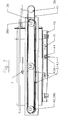
- the knitting loom illustrated in Figures 1-3 has two needle beds 1, 2, in which a plurality of parallel guide grooves 1a, respectively 2a are formed. Knitting needles 3 are slidably mounted in these guide grooves 1a, 2a. These needle beds 1, 2 form an angle between them, chosen so that their respective knitting needles 3 do not intersect not during their normal knitting runs.
- the knitting loom comprises a device comprising two plates 4, 5 held parallel to each other by spacers 6 fixed by screws 7.
- the plates 4 arranged adjacent in the beds 1, 2 have two rows of openings ovals 8a, 8b.
- the oval openings 8a 8b of the two rows are arranged longitudinally along each and are spread over the two rows so that the centers of the respective respective roundings of two openings 8a, 8b successive of the two rows lie on a line parallel to the guide grooves 1a, 2a of the needles 3 of respective beds 1, 2 ( Figure 2). Thanks to this arrangement, the rectilinear parts of these oval openings are succeed without end from one end to the other of the needle beds respective 1, 2 alternating from one row to another.
- Each oval opening 8a, 8b receives a guide core 9a, 9b which provides a closed loop guide slot 10a, 10b of equal width between the oval opening 8a, 8b and the respective guide core 9a, 9b.
- Each guide core 9a, 9b is positioned in the respective oval opening 8a, 8b by two positioning rods 11a, respectively 11b which are positioned and fixed in the parallel plate 5 by screws 12a, 12b.
- a double pinion 13a, 13a ', 13b, 13b' is pivotally mounted on one of the rods of each pair of positioning rods 11a, 11b integral with the same guide core 9a, 9b. Only a pinion 13a, respectively 13b is pivotally mounted on the other rod 11a, 11b secured to the same core of guide 9a, 9b.
- the two pinions 13a, and the two pinions 13b, integral with the same guide core 9a, respectively 9b are kinematically connected to each other by a endless belt 14a, 14b.
- the pinions 13a ', 13b' they are engaged with an endless belt 15 driven by a motor pinion 16, connected to the drive motor (not shown) of the knitting loom by a cardan shaft 17 and a bevel gear 18 engaged with a bevel gear 19 of a drive shaft 20 of the wire guides 21.
- these thread guides are integral with an endless belt 22 in taken with two pinions 23a, 23b, one of which 23a is coaxial and secured to a pinion 24 connected to a pinion 25 secured of the drive shaft 20 by an endless belt 26.
- the endless belts 14a, 14b are each engaged with one or more sliding supports 27a, 27b each comprising a sort of flange 27a 1 , 27b 1 ( Figures 4, 4b). These flanges 27a 1 , 27b 1 are engaged in guide grooves 28a, respectively 28b formed in the thickness of the edges of the oval openings 8a, 8b and of the guide cores 9a, 9b, delimiting closed loop guide slots 10a, 10b.
- the guide cores 9a, 9b are preferably made in two assembled parts 9a 1 , 9a 2 , respectively 9b 1 , 9b 2 , to allow the introduction of the flanges 27a 1 , 27b 1 of the sliding supports in the grooves guides 28a, 28b.
- Each sliding support 27a, 27b carries a pair of knitting cams ( Figures 5, 5b), an ascending cam in two parts 29 30 and a felling cam 51, intended for engaging the pushers 31a, 31b of the needles knitting 3.
- Each knitting cam 29, 30, 51 is integral a push rod 32, respectively 33.
- FIG. 6 illustrates the mechanism for moving the cams 29, 30 from one to the other of their positions.
- This mechanism has two symmetrical support arms 48 to which two levers 49 are articulated.
- Each of these levers 49 has a slot 49a in which a pegs 50a of a slide 50 can slide.
- Each slide 50 has a cam-shaped slot 50b, each being engaged with a pin 32a, respectively 33a of one of the push rods 32, 33.
- the levers 49 tilt in either of their positions (see Figure 6) and put the knitting cams 29, 30 on or off.
- each of these sliding supports 27a, 27b carries two guide rollers 42 (FIG. 4b) which press against a same edge of the slots 10a, 10b.
- the sliding supports 27a, 27b engaged with the endless belts 14a, 14b are driven according to trajectories defined by the slots 10a, 10b. Only one right part of the oval trajectory thus described by sliding supports 27a, 27b is used to actuate the needle pushers 31a, 31b. This right part is that in which the sliding supports 27a, 27b and so the knitting cams 29, 30, 51 which they carry move in the direction of the arrows F.
- the variant illustrated in Figure 7 does not differ from that illustrated in Figures 1-6 only by the fact that at instead of having two rows of oval loops 8a, 8b on which run the sliding supports 27a, 27b carrying knitting cams 29, 30, 51 this variant does not include that a single belt 36 making the entire length of the bed and guided by pulleys 38a, 38b.
- training knitting cam supports 37 integral with the belt endless 36 is obtained by a drive pulley 39 connected to a pinion 40 coaxial to pinion 38b by a drive belt 41.
- the knitting cams 37 move along the entire length of the knitting loom in the direction of arrow F on the upper end of the endless belt 36 where they selectively engage the pushers knitting needles 3 and come back in the opposite direction along the lower strand of this belt 36 where the stops can move the cams according to the needles selected, as previously described in relation to the first form of execution.
- FIG. 7 also shows a mechanism for adjusting the length of the meshes which applies both to this variant and to the previous embodiment.
- Each needle bed 1, 2 is secured to arms 43 each of which carries a pin 43a which projects on one of its faces to engage in a slot-shaped cam 44 formed in an adjustment member 45 slidably mounted on the frame (not shown) of the knitting loom, in the direction of the double arrow F 1 .
- the cams 44 in the form of slots make it possible to move the needle beds 1, 2 parallel to the knitting needles 3, so that the relative position between the knitting needles 3 and the felling plates 46 ( Figure 3) and therefore the length of the mesh.
- the knitting loom according to the invention offers all the knitting possibilities of a conventional loom with regard to concerns the selection of needles and the adjustment of lengths of meshes.
- the mass of the sliding supports 27a, 27b has nothing comparable to that of a conventional cart, this which allows a significant increase in the knitting speed.
Landscapes
- Engineering & Computer Science (AREA)
- Textile Engineering (AREA)
- Knitting Machines (AREA)
Priority Applications (1)
| Application Number | Priority Date | Filing Date | Title |
|---|---|---|---|
| EP01810908A EP1295976A1 (de) | 2001-09-19 | 2001-09-19 | Flachstrickmaschine zur Herstellung schlauchförmiger Gestricke |
Applications Claiming Priority (1)
| Application Number | Priority Date | Filing Date | Title |
|---|---|---|---|
| EP01810908A EP1295976A1 (de) | 2001-09-19 | 2001-09-19 | Flachstrickmaschine zur Herstellung schlauchförmiger Gestricke |
Publications (1)
| Publication Number | Publication Date |
|---|---|
| EP1295976A1 true EP1295976A1 (de) | 2003-03-26 |
Family
ID=8184146
Family Applications (1)
| Application Number | Title | Priority Date | Filing Date |
|---|---|---|---|
| EP01810908A Withdrawn EP1295976A1 (de) | 2001-09-19 | 2001-09-19 | Flachstrickmaschine zur Herstellung schlauchförmiger Gestricke |
Country Status (1)
| Country | Link |
|---|---|
| EP (1) | EP1295976A1 (de) |
Cited By (1)
| Publication number | Priority date | Publication date | Assignee | Title |
|---|---|---|---|---|
| EP1760176A1 (de) * | 2005-08-29 | 2007-03-07 | Anton Percy Spielmann | Vorrichtung zum Stricken von Rechts- und Linksmaschen auf demselben Nadelbett |
Citations (3)
| Publication number | Priority date | Publication date | Assignee | Title |
|---|---|---|---|---|
| GB1550848A (en) * | 1975-07-16 | 1979-08-22 | Sulzer Morat Gmbh | Knitting machine |
| WO1995000689A1 (en) * | 1993-06-23 | 1995-01-05 | Lambda S.R.L. | Knitting machine for the production of tights (pantihose) and the like |
| EP1127970A1 (de) * | 2000-02-23 | 2001-08-29 | Anton Percy Spielmann | Verfahren und Flachstrickmaschine zur Herstellung von nahtlosen schlauchförmigen Strickwaren |
-
2001
- 2001-09-19 EP EP01810908A patent/EP1295976A1/de not_active Withdrawn
Patent Citations (3)
| Publication number | Priority date | Publication date | Assignee | Title |
|---|---|---|---|---|
| GB1550848A (en) * | 1975-07-16 | 1979-08-22 | Sulzer Morat Gmbh | Knitting machine |
| WO1995000689A1 (en) * | 1993-06-23 | 1995-01-05 | Lambda S.R.L. | Knitting machine for the production of tights (pantihose) and the like |
| EP1127970A1 (de) * | 2000-02-23 | 2001-08-29 | Anton Percy Spielmann | Verfahren und Flachstrickmaschine zur Herstellung von nahtlosen schlauchförmigen Strickwaren |
Cited By (5)
| Publication number | Priority date | Publication date | Assignee | Title |
|---|---|---|---|---|
| EP1760176A1 (de) * | 2005-08-29 | 2007-03-07 | Anton Percy Spielmann | Vorrichtung zum Stricken von Rechts- und Linksmaschen auf demselben Nadelbett |
| WO2007025400A1 (fr) * | 2005-08-29 | 2007-03-08 | Spielmann, William, Steven | Dispositif pour tricoter des mailles a l'envers et l'endroit sur une meme fonture |
| US7647793B2 (en) | 2005-08-29 | 2010-01-19 | Anton Percy Spielmann | Device for knitting reverse and face stitches on a common needle bed |
| CN101253288B (zh) * | 2005-08-29 | 2011-08-03 | 威廉·史蒂文·施皮尔曼 | 单针座正反针针织机 |
| KR101315339B1 (ko) * | 2005-08-29 | 2013-10-08 | 앙똥 뻬르씨 스삐엘망 | 공통 바늘 베드에서 정면 바늘땀과 뒷면 바늘땀을 편물하는장치 |
Similar Documents
| Publication | Publication Date | Title |
|---|---|---|
| EP0839941A1 (de) | Schlauchförmige Flechtstruktur für Verbundbauteil, deren Herstellung und Anwendungen | |
| FR2550807A1 (fr) | Appareils d'avance et d'orientation d'etoffes molles par rapport a une machine a coudre | |
| FR2646176A1 (fr) | Procede et moyens pour monter un tissu tricote sur un metier a tricoter rectiligne | |
| FR2698890A3 (fr) | Système de commande de dispositifs de changement de guide-fils pour métiers à tricoter. | |
| EP0045758B1 (de) | Vorrichtung zum heben der kettfäden in einem webstuhl und mit einer solchen vorrichtung ausgerüsteter webstuhl | |
| CH615230A5 (en) | Drive assembly for spinning machine | |
| EP1295976A1 (de) | Flachstrickmaschine zur Herstellung schlauchförmiger Gestricke | |
| BE1003884A5 (fr) | Procede de tuftage et dispositif pour la mise en oeuvre de ce procede. | |
| FR2482985A1 (fr) | Dispositif de commande pour la roue dentee d'entrainement d'un porteur de fil de trame d'une machine a tisser sans navette | |
| FR2461049A1 (fr) | Dispositif et procede de tricotage a deux dimensions, avec un guide-fil oscillant par rapport a l'axe d'une tige de trame | |
| CH643015A5 (fr) | Metier a tricoter. | |
| EP0285553B1 (de) | Steuervorrichtung für die Strickstellung der Nadeln an einer Strickmaschine | |
| EP0353511B1 (de) | Bestandteile einer Vorrichtung zum Herstellen einer Reifenverstärkung | |
| FR2478683A1 (fr) | Metier a tisser du type a pinces | |
| FR2655359A1 (fr) | Dispositif pour tisser a chaine croisee le bord lateral d'un tissu dans un metier a tisser. | |
| CH664776A5 (fr) | Dispositif de selection de fils pour metier a tricoter. | |
| EP1734165B1 (de) | Schussfadeneintragsvorrichtung für eine Webmaschine zum Herstellen von zweilagige Gewebe und Webmaschine mit einer solchen Vorrichtung | |
| EP0131495A1 (de) | Vorrichtung zum Herstellen einer Dreherfachleiste in Webmaschinen | |
| WO2001063031A1 (fr) | Procede et metier a tricoter rectiligne pour former un tricot tubulaire sans couture | |
| EP0127184A1 (de) | Webmaschine | |
| EP1069219B1 (de) | Kantenfachbildungsvorrichtung sowie Webmaschine mit einer solchen Vorrichtung | |
| BE481007A (de) | ||
| FR2735796A1 (fr) | Metier a tisser le velours faconne de soierie | |
| FR2608643A1 (fr) | Dispositif pour former mecaniquement une croisure de fils, sur une machine textile | |
| BE375419A (de) |
Legal Events
| Date | Code | Title | Description |
|---|---|---|---|
| PUAI | Public reference made under article 153(3) epc to a published international application that has entered the european phase |
Free format text: ORIGINAL CODE: 0009012 |
|
| AK | Designated contracting states |
Kind code of ref document: A1 Designated state(s): AT BE CH CY DE DK ES FI FR GB GR IE IT LI LU MC NL PT SE TR Designated state(s): AT BE CH CY DE DK ES FI FR GB GR IE IT LI LU MC NL PT SE TR |
|
| AX | Request for extension of the european patent |
Extension state: AL LT LV MK RO SI |
|
| AKX | Designation fees paid | ||
| REG | Reference to a national code |
Ref country code: DE Ref legal event code: 8566 |
|
| STAA | Information on the status of an ep patent application or granted ep patent |
Free format text: STATUS: THE APPLICATION IS DEEMED TO BE WITHDRAWN |
|
| 18D | Application deemed to be withdrawn |
Effective date: 20030927 |