EP1294460B1 - Dispositif de piegeage de produits a eliminer, a usage industriel ou medical - Google Patents
Dispositif de piegeage de produits a eliminer, a usage industriel ou medical Download PDFInfo
- Publication number
- EP1294460B1 EP1294460B1 EP01947552A EP01947552A EP1294460B1 EP 1294460 B1 EP1294460 B1 EP 1294460B1 EP 01947552 A EP01947552 A EP 01947552A EP 01947552 A EP01947552 A EP 01947552A EP 1294460 B1 EP1294460 B1 EP 1294460B1
- Authority
- EP
- European Patent Office
- Prior art keywords
- container
- walls
- duct
- inflatable
- products
- Prior art date
- Legal status (The legal status is an assumption and is not a legal conclusion. Google has not performed a legal analysis and makes no representation as to the accuracy of the status listed.)
- Expired - Lifetime
Links
Images


Classifications
-
- B—PERFORMING OPERATIONS; TRANSPORTING
- B01—PHYSICAL OR CHEMICAL PROCESSES OR APPARATUS IN GENERAL
- B01D—SEPARATION
- B01D17/00—Separation of liquids, not provided for elsewhere, e.g. by thermal diffusion
-
- B—PERFORMING OPERATIONS; TRANSPORTING
- B01—PHYSICAL OR CHEMICAL PROCESSES OR APPARATUS IN GENERAL
- B01D—SEPARATION
- B01D17/00—Separation of liquids, not provided for elsewhere, e.g. by thermal diffusion
- B01D17/02—Separation of non-miscible liquids
- B01D17/0208—Separation of non-miscible liquids by sedimentation
-
- B—PERFORMING OPERATIONS; TRANSPORTING
- B01—PHYSICAL OR CHEMICAL PROCESSES OR APPARATUS IN GENERAL
- B01D—SEPARATION
- B01D21/00—Separation of suspended solid particles from liquids by sedimentation
-
- B—PERFORMING OPERATIONS; TRANSPORTING
- B01—PHYSICAL OR CHEMICAL PROCESSES OR APPARATUS IN GENERAL
- B01D—SEPARATION
- B01D21/00—Separation of suspended solid particles from liquids by sedimentation
- B01D21/0003—Making of sedimentation devices, structural details thereof, e.g. prefabricated parts
-
- B—PERFORMING OPERATIONS; TRANSPORTING
- B01—PHYSICAL OR CHEMICAL PROCESSES OR APPARATUS IN GENERAL
- B01D—SEPARATION
- B01D21/00—Separation of suspended solid particles from liquids by sedimentation
- B01D21/0012—Settling tanks making use of filters, e.g. by floating layers of particulate material
-
- B—PERFORMING OPERATIONS; TRANSPORTING
- B01—PHYSICAL OR CHEMICAL PROCESSES OR APPARATUS IN GENERAL
- B01D—SEPARATION
- B01D21/00—Separation of suspended solid particles from liquids by sedimentation
- B01D21/003—Sedimentation tanks provided with a plurality of compartments separated by a partition wall
-
- B—PERFORMING OPERATIONS; TRANSPORTING
- B01—PHYSICAL OR CHEMICAL PROCESSES OR APPARATUS IN GENERAL
- B01D—SEPARATION
- B01D21/00—Separation of suspended solid particles from liquids by sedimentation
- B01D21/24—Feed or discharge mechanisms for settling tanks
- B01D21/2405—Feed mechanisms for settling tanks
-
- B—PERFORMING OPERATIONS; TRANSPORTING
- B01—PHYSICAL OR CHEMICAL PROCESSES OR APPARATUS IN GENERAL
- B01D—SEPARATION
- B01D2221/00—Applications of separation devices
- B01D2221/10—Separation devices for use in medical, pharmaceutical or laboratory applications, e.g. separating amalgam from dental treatment residues
Definitions
- the present invention relates to a device for trapping products to be eliminated, for industrial or medical use.
- Known trapping devices are generally of complex and expensive structure. They include disposable or washable parts, such as filters or bags, but also fixed parts that remain contamina- tor even if their maintenance is ensured perfectly, since their sterilization can not be assured. In addition, these devices can not guarantee a 100% trapping of biological and toxic waste, such as mercury, which must however be eliminated in perfectly controlled dies.
- the present invention aims to provide a particularly simple and economical device that guarantees a perfect safety vis-à-vis the risk of contamination.
- the subject of the present invention is a device for trapping products to be eliminated, constituted by a closed container provided with a product supply duct and a suction duct, characterized in that said container comprises at least one wall inflatable which is flexible when deflated and makes the container space-saving and rigid when inflated, the container then being rigid enough that suction through the suction pipe creates a vacuum that sucks products to be eliminated in the container through the product supply duct.
- the inflation of said at least one wall gives the container sufficient rigidity to form at least a portion of its frame.
- the product trapping device can suck up the products to be eliminated, by simple depression of its interior.
- the device comprises two inflatable walls which form two opposite walls of the closed container and are supplemented by flexible walls stretched between them after inflation and / or by rigid flat walls.
- the device comprises a single inflatable wall and, opposite it, an articulation connecting two rigid walls joining said inflatable wall, as well as flexible walls stretched between the inflatable and rigid walls.
- the inflatable walls are toric and define the periphery of the container.
- the device comprises a suction duct intended to be connected to a vacuum pump intended to create a vacuum in the closed container.
- the device according to the invention can be made of a sufficiently economical material for said device to be disposable, the unique use of the device being the most effective parade to the risk of infection or contamination.
- the device according to the invention finds particular application in medicine, and more particularly in hospital, where it can be a means of fighting against nosocomial infections.
- the device according to the invention When its or its inflatable walls are deflated, the device according to the invention is compact. It may for example be in the form of a flattened rectangle configuration that facilitates storage.
- the device according to the invention can in particular be combined with the disposable unit described in the French patent application published under No. 2,775,184 in the name of the same applicant.
- this combination provides a complete equipment that solves both the problems of connection and the problems of disposal of biological and toxic products, such as mercury in wastewater.
- the device according to the invention provides a security vis-à-vis pollution and contamination problems because its operation is not based on filtering products but on their trapping.
- the container Once the container is filled, its product supply duct may be sealed, for example by heat sealing, so that the trapping of the products becomes final, and an identification, for example by bar code, may be carried on the device to facilitate its collection. , its traceability and the reprocessing of the trapped products.
- an identification for example by bar code
- the suction duct is provided with a filter whose function is to maintain inside the container vaporized products which could, in the absence of such a filter, escape because of the introduction of air or new waste into the container.
- This filter may, in addition, be constituted by or contain a disinfectant product for purifying the air escaping from the container.
- the suction duct is provided with a safety valve which prevents the container from overflowing through this duct in case of complete filling with a liquid.
- Such a valve may for example be constituted by a floating ball held opposite the mouth, in the form of a seat, of the duct and capable of closing it by being pressed against said seat when the liquid level reaches a certain height. in the container.
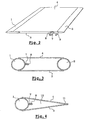
- the device of FIG. 1 comprises a closed container formed by two opposite inflatable walls 1, 2, joined by two rigid flat walls 3, 4, by a flexible base 5 and by a flexible upper wall 6.
- a product supply duct 7 passes through the upper wall 6 and extends inside the container to the vicinity of its bottom 5.
- a suction duct 8 also passes through the wall 6 and opens into the upper part of the container.
- the suction duct 8 is intended to be connected to a vacuum pump (not shown) which creates a vacuum in the container and forces the suction of the products through the supply duct 7.
- An inflation duct 9 allows the filling of the inflatable walls 1 and 2.
- the wall 2 inflates at the same time as the wall 1 through a channel 10 formed in the upper wall 6 and connecting the two walls.
- the wall 2 has its own inflation duct.
- the walls 1 and 2 inflated take a cylindrical shape. Their diameter determines the thickness of the container.
- the rigid flat walls 3 and 4 are kept apart from each other by the inflated walls 1 and 2, while the flexible walls 5 and 6 are stretched between the rigid walls and the inflated walls.
- the container When the walls 1 and 2 are not inflated, the container is in the form of a flattened rectangular plate, the two rigid walls 3 and 4 being glued together, as shown in FIG.
- the device traps the products sucked up by the duct 7 under the effect of the vacuum created by the vacuum pump connected to the duct 8.
- the rigidity conferred by the inflatable walls is indeed sufficient for the device to resist this depression and suction to occur through the conduit 7.
- conduits 7 and 8 are closed, for example by welding, gluing, ligation or folding.
- the device can then be sent safely to a waste reprocessing plant.
- the container differs from the previous one only in replacing the inflatable wall 2 by a hinge 11 connecting the two rigid walls 3 and 4 and replacing the two rectangular flexible walls 5 and 6 by triangular soft walls 12
- This embodiment can be simpler and cheaper to achieve than the previous one.
- the container is empty at the beginning of use.
- Another possibility of using the device according to the invention is to fill it, prior to its use, with a sparging liquid whose level arrives above the lower end of the product supply duct 7.
- the device can then be used to disinfect and / or treat the air drawn by the pump before it enters the fixed parts of the installation.
- FIG. 5 illustrates another embodiment in which the container 13 comprises four compartments 14, 15, 16, 17 each of which has a substantially triangular section in the manner of the container of FIG. 4.
- Each compartment is equipped with a cylindrical inflatable wall 18-21 which gives it its rigidity and its volume.
- conduits 22-24 which connect the upper part of a container with the lower part of the neighboring container.
- a product supply duct 25 located at the hinge of the four compartments opens in the lower part of the compartment 14, while a suction duct 26 opens into the upper part of the compartment 17.
- the device 13 ensures that the recovered products are retained in its compartments and that the air sucked through it is free of dirt, which avoids the pollution of the fixed pipes and the vacuum pump.
- the splash liquid can be introduced into the container at the time of use of the container, through the opening 27 provided for this purpose.
- the compartment 16 is pre-filled, in which case it is necessary to provide breakable shutters of the conduits 23 and 24 so that the liquid remains in the compartment 16 during storage of the device.
- the four compartments consist of two containers each comprising two compartments and interconnected so as to achieve the concatenation of compartments which has just been described.
- One of the compartments, that located upstream, retains the aspirated products and must be replaced after each use or in any case quite frequently.
- the other compartment, located downstream, contains the sparging liquid and can be stored longer.
- all the walls of the container may be inflatable.
Description
- La présente invention concerne un dispositif de piégeage de produits à éliminer, à usage industriel ou médical.
- Il est connu que certains produits doivent impérativement être éliminés dans des conditions de sûreté maximale, tant au moment de leur capture qu'au moment de leur stockage en vue d'un retraitement.
- Les dispositifs de piégeage connus sont généralement de structure complexe et coûteuse. Ils comportent des parties jetables ou lavables, comme par exemple des filtres ou des sacs, mais également des parties fixes qui demeurent contaminatrices même si leur entretien est assuré de façon parfaite, étant donné que leur stérilisation ne peut, elle, être assurée. En outre, ces dispositifs ne peuvent garantir un piégeage à 100 % des déchets biologiques et toxiques, tels que le mercure, qui doivent cependant être éliminés dans des filières parfaitement contrôlées.
- La nécessité de réaliser ce piégeage existe cependant, ce qui oblige par exemple les chirurgiens dentistes à s'équiper de séparateurs d'amalgame.
- Un autre inconvénient des dispositifs connus est qu'ils requièrent souvent la présence d'appareillages pour leur fonctionnement ou pour leur entretien, ce qui peut occasionner des frais substantiels indésirables.
- La présente invention vise à proposer un dispositif particulièrement simple et économique qui garantit une parfaite sécurité vis-à-vis des risques de contamination.
- La présente invention a pour objet un dispositif de piégeage de produits à éliminer, constitué par un récipient fermé muni d'un conduit d'amenée de produits et d'un conduit d'aspiration, caractérisé en ce que ledit récipient comporte au moins une paroi gonflable qui est souple lorsqu'elle est dégonflée et rend le récipient peu encombrant et rigide lorsqu'elle est gonflée, le récipient étant alors assez rigide pour qu'une aspiration par le conduit d'aspiration crée une dépression qui aspire des produits à éliminer dans le récipient par le conduit d'amenée de produits.
- Selon l'invention, le gonflage de ladite au moins une paroi confère au récipient une rigidité suffisante pour constituer au moins une partie de son armature.
- De cette manière, le dispositif de piégeage de produits peut aspirer les produits à éliminer, par simple mise en dépression de son intérieur.
- Dans un mode de réalisation particulier de l'invention, le dispositif comporte deux parois gonflables qui forment deux parois opposées du récipient fermé et sont complétées par des parois souples tendues entre elles après gonflage et/ou par des parois planes rigides.
- Dans un autre mode de réalisation, le dispositif comporte une seule paroi gonflable et, à l'opposé de celle-ci, une articulation reliant deux parois rigides rejoignant ladite paroi gonflable, ainsi que des parois souples tendues entre les parois gonflables et rigides.
- Dans un autre mode de réalisation, les parois gonflables sont toriques et définissent la périphérie du récipient.
- Dans un mode de réalisation particulier de l'invention, le dispositif comporte un conduit d'aspiration destiné à être raccordé à une pompe à vide destinée à créer une dépression dans le récipient fermé.
- Compte tenu de sa simplicité, le dispositif selon l'invention peut être réalisé en un matériau suffisamment économique pour que ledit dispositif soit jetable, l'usage unique du dispositif étant la parade la plus efficace aux risques d'infection ou de contamination.
- Le dispositif selon l'invention trouve notamment son application en médecine, et plus particulièrement en milieu hospitalier, où il peut constituer un moyen de lutte contre les infections nosocomiales.
- Lorsque sa ou ses parois gonflables sont dégonflées, le dispositif selon l'invention est peu encombrant. Il peut par exemple se présenter sous la forme d'un rectangle aplati, configuration qui facilite son stockage.
- Le dispositif selon l'invention peut en particulier être combiné à l'unit jetable décrit dans la demande de brevet français publiée sous le numéro 2.775.184 au nom du même déposant.
- Dans le cas particulier des cabinets dentaires, cette combinaison fournit un matériel complet qui résout à la fois les problèmes de branchement et les problèmes d'élimination des produits biologiques et toxiques, tels que les mercures dans les eaux usées.
- D'une manière générale, le dispositif selon l'invention procure une sécurité vis-à-vis des problèmes de pollution et de contamination du fait que son fonctionnement ne repose pas sur un filtrage des produits mais sur leur piégeage.
- Une fois le récipient rempli, son conduit d'amenée de produits peut être scellé par exemple par thermosoudage, afin que le piégeage des produits devienne définitif, et une identification, par exemple par code barre, peut être portée sur le dispositif pour faciliter sa collecte, sa traçabilité et le retraitement des produits piégés.
- Dans un mode de réalisation particulier de l'invention, le conduit d'aspiration est muni d'un filtre dont la fonction est de maintenir à l'intérieur du récipient des produits vaporisés qui pourraient, en l'absence d'un tel filtre, s'échapper du fait de l'introduction d'air ou de nouveaux déchets dans le récipient. Ce filtre peut, en outre, être constitué par ou contenir un produit désinfectant visant à purifier l'air s'échappant du récipient.
- Dans un autre mode de réalisation, compatible avec le précédent, le conduit d'aspiration est muni d'un clapet de sécurité qui empêche le récipient de déborder par ce conduit en cas de remplissage complet par un liquide.
- Un tel clapet peut par exemple être constitué par une bille flottante maintenue en regard de l'embouchure, en forme de siège, du conduit et susceptible de l'obturer en venant s'appliquer contre ledit siège lorsque le niveau de liquide atteint une certaine hauteur dans le récipient.
- Dans le but de mieux faire comprendre l'invention, on va en décrire maintenant trois modes de réalisation donnés à titre d'exemples non limitatifs de la portée de l'invention, en référence au dessin annexé dans lequel :
- la figure 1 est une vue en perspective d'un dispositif selon un mode de réalisation de l'invention,
- la figure 2 est une vue en perspective du même dispositif en configuration de stockage,
- la figure 3 est une vue en coupe selon III-III de la figure 1,
- la figure 4 est une vue analogue à la figure 3 d'un dispositif selon un autre mode de réalisation.
- la figure 5 est une vue en perspective d'un dispositif selon un autre mode de réalisation de l'invention,
- la figure 6 est une vue en coupe selon VI-VI de la figure 5.
- Le dispositif de la figure 1 comprend un récipient fermé formé par deux parois gonflables opposées 1, 2, réunies par deux parois planes rigides 3, 4, par un fond souple 5 et par une paroi supérieure souple 6.
- Un conduit d'amenée de produits 7 traverse la paroi supérieure 6 et s'étend à l'intérieur du récipient jusqu'au voisinage de son fond 5.
- Un conduit d'aspiration 8 traverse également la paroi 6 et débouche en partie supérieure du récipient.
- Le conduit d'aspiration 8 est destiné à être raccordé à une pompe à vide (non représentée) qui crée un vide dans le récipient et force l'aspiration des produits à travers le conduit d'amenée 7.
- Un conduit de gonflage 9 permet le remplissage des parois gonflables 1 et 2.
- Dans le mode de réalisation illustré ici, la paroi 2 se gonfle en même temps que la paroi 1 grâce à un canal 10 formé dans la paroi supérieure 6 et reliant les deux parois.
- Dans une variante non illustrée, la paroi 2 comporte son propre conduit de gonflage.
- Comme on le voit mieux à la figure 3, les parois 1 et 2 gonflées prennent une forme cylindrique. Leur diamètre détermine l'épaisseur du récipient.
- Les parois planes rigides 3 et 4 sont maintenues écartées l'une de l'autre par les parois gonflées 1 et 2, tandis que les parois souples 5 et 6 sont tendues entre les parois rigides et les parois gonflées.
- Lorsque les parois 1 et 2 ne sont pas gonflées, le récipient se présente sous la forme d'une plaque rectangulaire aplatie, les deux parois rigides 3 et 4 étant collées l'une contre l'autre, ainsi que représente à la figure 2.
- Dans cette configuration, plusieurs dispositifs peuvent être facilement stockés en piles, ce qui est avantageux pour un dispositif à usage unique consommé en grandes quantités.
- Comme on le voit à la figure 1, lors de son utilisation, le dispositif piège les produits aspirés par le conduit 7 sous l'effet de la dépression créée par la pompe à vide reliée au conduit 8. La rigidité conférée par les parois gonflables est en effet suffisante pour que le dispositif résiste à cette dépression et qu'une aspiration se produise par le conduit 7.
- Lorsque le récipient est complètement rempli, les conduits 7 et 8 sont obturés, par exemple par soudage, collage, ligature ou pliage.
- Le dispositif peut ensuite être envoyé en toute sécurité dans une usine de retraitement des déchets.
- Dans le mode de réalisation de la figure 4, le récipient ne diffère du précédent que par le remplacement de la paroi gonflable 2 par une charnière 11 reliant les deux parois rigides 3 et 4 et par le remplacement des deux parois souples rectangulaires 5 et 6 par des parois souples triangulaires 12
- Ce mode de réalisation peut s'avérer plus simple et économique à réaliser que le précédent.
- Dans les modes de réalisation qui viennent d'être décrits, le récipient est vide en début d'utilisation.
- Une autre possibilité d'utilisation du dispositif selon l'invention est de le remplir, préalablement à son utilisation, d'un liquide de barbotage dont le niveau arrive au dessus de l'extrémité inférieure du conduit d'amenée de produits 7. Le dispositif peut alors être utilisé pour désinfecter et/ou traiter l'air aspiré par la pompe avant qu'il ne pénètre dans les parties fixes de l'installation.
- La figure 5 illustre un autre mode de réalisation dans lequel le récipient 13 comprend quatre compartiments 14, 15, 16, 17 dont chacun présente une section sensiblement triangulaire à la manière du récipient de la figure 4.
- Chaque compartiment est muni d'une paroi gonflable cylindrique 18-21 qui lui confère sa rigidité et son volume.
- Comme on le voit à la figure 6, les quatre compartiments 14-17 communiquent deux à deux par des conduits 22-24 qui relient la partie supérieure d'un récipient avec la partie inférieure du récipient voisin.
- En outre, un conduit d'amenée de produits 25 situé à la charnière des quatre compartiments débouche en partie inférieure du compartiment 14, tandis qu'un conduit d'aspiration 26 débouche en partie supérieure du compartiment 17.
- On comprend que l'air circulant dans le dispositif traverse successivement tes compartiments 14, 15, 16 et 17.
- Ainsi, les quatre compartiments peuvent être utilisés pour remplir les fonctions suivantes :
- compartiment 14 : récupération des matières solides et liquides aspirées,
- compartiment 15 : récupération des fuites éventuelles provenant du compartiment 14,
- compartiment 16 : barbotage dans un liquide de stérilisation/traitement de l'air provenant des compartiments 14 et 15,
- compartiment 17: récupération des fuites éventuelles provenant du compartiment 16.
- Le dispositif 13 garantit que les produits récupérés sont retenus dans ses compartiments et que l'air aspiré à travers lui est exempt de souillures, ce qui évite la pollution des conduites fixes et de la pompe à vide.
- Le liquide de barbotage peut être introduit dans le récipient au moment de l'utilisation du récipient, par l'ouverture 27 prévue à cet effet. Une autre possibilité est que le compartiment 16 soit pré-rempli, auquel cas il faut prévoir des obturateurs sécables des conduits 23 et 24 afin que le liquide demeure dans le compartiment 16 lors du stockage du dispositif.
- Dans une variante (non représentée) du même dispositif, les quatre compartiments sont constitués par deux récipients comprenant chacun deux compartiments et reliés entre eux de manière à réaliser l'enchaînement de compartiments qui vient d'être décrit
- L'un des compartiments, celui situé en amont, retient les produits aspirés et doit être remplacé après chaque utilisation ou en tout cas assez fréquemment.
- L'autre compartiment, situé en aval, contient le liquide de barbotage et peut être conservé plus longtemps.
- Les modes de réalisation ci-dessus ne sont fournis qu'à titre d'exemples pour bien faire comprendre l'invention, laquelle n'est nullement limitée aux caractéristiques décrites en référence à cet exemple.
- En particulier, toutes les parois du récipient peuvent être gonflables.
- De plus, aucune limitation dimensionnelle ne s'impose quant aux parois du récipient, lequel pourrait être de très grande taille pour être placé à proximité d'une usine afin d'y collecter tous les produits devant impérativement être récupérés.
Claims (7)
- Dispositif de piégeage de produits à éliminer, constitué par un récipient fermé muni d'un conduit (7, 25) d'amenée de produits et d'un conduit d'aspiration (8,26), caractérisé en ce que ledit récipient comporte au moins une paroi gonflable (1, 2, 18-21) qui est souple lorsqu'elle est dégonflée et rend le récipient peu encombrant et rigide lorsqu'elle est gonflée, le récipient étant alors assez rigide pour qu'une aspiration par le conduit d'aspiration crée une dépression qui aspire des produits à éliminer dans le récipient par le conduit d'amenée de produits.
- Dispositif selon la revendication 1, caractérisé en ce qu'il comporte deux parois gonflables (1, 2) qui forment deux parois opposées du récipient fermé et sont complétées par des parois souples (5, 6) tendues entre elles après gonflage et/ou par des parois planes rigides (3, 4).
- Dispositif selon la revendication 1, caractérisé en ce qu'il comporte une seule paroi gonflable (1) et, à l'opposé de celle-ci, une articulation (11) reliant deux parois rigides (3, 4) rejoignant ladite paroi gonflable (1), ainsi que des parois souples (12, 13) tendues entre les parois gonflables et rigides.
- Dispositif selon l'une quelconque des revendications 1 à 3, caractérisé en ce qu'il comporte un conduit d'aspiration (8, 26) destiné à être raccordé à une pompe à vide qui crée une dépression dans le récipient.
- Dispositif selon l'une quelconque des revendications 1 à 4, caractérisé en ce que le conduit d'aspiration est muni d'un filtre.
- Dispositif selon l'une quelconque des revendications 1 à 5, caractérisé en ce que le conduit d'aspiration est muni d'un clapet de sécurité qui empêche le récipient de déborder par ce conduit en cas de remplissage complet par un liquide.
- Dispositif selon l'une quelconque des revendications 1 à 6, caractérisé en ce qu'il comporte plusieurs compartiments (14-17) reliés deux à deux par des conduits (22,23,24).
Applications Claiming Priority (3)
| Application Number | Priority Date | Filing Date | Title |
|---|---|---|---|
| FR0007837A FR2810306B1 (fr) | 2000-06-20 | 2000-06-20 | Dispositif de piegeage de produits a eliminer et combinaison d'un tel dispositif avec une pompe a vide |
| FR0007837 | 2000-06-20 | ||
| PCT/FR2001/001938 WO2001097942A1 (fr) | 2000-06-20 | 2001-06-20 | Dispositif de piegeage de produits a eliminer, a usage industriel ou medical |
Publications (2)
| Publication Number | Publication Date |
|---|---|
| EP1294460A1 EP1294460A1 (fr) | 2003-03-26 |
| EP1294460B1 true EP1294460B1 (fr) | 2006-01-04 |
Family
ID=8851432
Family Applications (1)
| Application Number | Title | Priority Date | Filing Date |
|---|---|---|---|
| EP01947552A Expired - Lifetime EP1294460B1 (fr) | 2000-06-20 | 2001-06-20 | Dispositif de piegeage de produits a eliminer, a usage industriel ou medical |
Country Status (6)
| Country | Link |
|---|---|
| EP (1) | EP1294460B1 (fr) |
| AT (1) | ATE314878T1 (fr) |
| AU (1) | AU2001269211A1 (fr) |
| DE (1) | DE60116493D1 (fr) |
| FR (1) | FR2810306B1 (fr) |
| WO (1) | WO2001097942A1 (fr) |
Family Cites Families (11)
| Publication number | Priority date | Publication date | Assignee | Title |
|---|---|---|---|---|
| GB2000272B (en) * | 1977-03-28 | 1982-03-17 | Prewer J | Method of and apparatus for utilizing solar energy |
| US4790936A (en) * | 1986-03-31 | 1988-12-13 | Renfrow John L | Collapsable oil spillage recovery system |
| JP2916682B2 (ja) * | 1988-07-28 | 1999-07-05 | 株式会社加藤製作所 | 汚泥の吸引、排出装置 |
| US5017135A (en) * | 1989-10-18 | 1991-05-21 | Ramvac Corporation | Trap and separator for denial vacuum systems |
| DE4131905A1 (de) * | 1991-04-17 | 1992-10-22 | Till Dr Ropers | Verfahren und vorrichtung zur abscheidung von schadstoffen, insbesondere von amalgam, aus den abwaessern von zahnarztpraxen |
| GB2269579A (en) * | 1992-08-14 | 1994-02-16 | John Richard Wickham Hardy | Waste product collection unit |
| US5601659A (en) * | 1995-03-13 | 1997-02-11 | Cyclone Surface Cleaning, Inc. | Mobile power wash system with water reclamation and hydrocarbon removal method |
| GB2301086B (en) * | 1995-05-23 | 1999-06-23 | Peter Thomas John Jefferis | Improvements in and relating to storage of fluid materials |
| DE19820840B4 (de) * | 1997-05-08 | 2008-02-21 | Storch Holding Gmbh | Sedimentierungseinrichtung |
| FR2775184B1 (fr) * | 1998-02-26 | 2000-05-05 | Michel Ravineau | Dispositif pour intervention chirurgicale destine a assurer une protection du patient contre les contaminations, notamment en chirurgie dentaire |
| CA2243580A1 (fr) * | 1998-07-24 | 2000-01-24 | Richard H. Chilibeck | Appareil et procede pour l'extraction de particules metalliques fines d'effluents de dechets liquides |
-
2000
- 2000-06-20 FR FR0007837A patent/FR2810306B1/fr not_active Expired - Fee Related
-
2001
- 2001-06-20 AU AU2001269211A patent/AU2001269211A1/en not_active Abandoned
- 2001-06-20 DE DE60116493T patent/DE60116493D1/de not_active Expired - Lifetime
- 2001-06-20 WO PCT/FR2001/001938 patent/WO2001097942A1/fr active IP Right Grant
- 2001-06-20 EP EP01947552A patent/EP1294460B1/fr not_active Expired - Lifetime
- 2001-06-20 AT AT01947552T patent/ATE314878T1/de not_active IP Right Cessation
Also Published As
| Publication number | Publication date |
|---|---|
| AU2001269211A1 (en) | 2002-01-02 |
| FR2810306A1 (fr) | 2001-12-21 |
| WO2001097942A1 (fr) | 2001-12-27 |
| DE60116493D1 (de) | 2006-03-30 |
| ATE314878T1 (de) | 2006-02-15 |
| FR2810306B1 (fr) | 2002-11-15 |
| EP1294460A1 (fr) | 2003-03-26 |
Similar Documents
| Publication | Publication Date | Title |
|---|---|---|
| EP0525493B1 (fr) | Appareil de récupération et de filtration du sang | |
| EP2645981B1 (fr) | Poche de distribution via une pluralité de ports de sortie d'un produit a usage biopharmaceutique a l'état général liquide ou pâteux. | |
| CA2209421C (fr) | Sachet de conditionnement de substances liquides biologiques a ouverture pelable pour introduction de canules, tubes et sondes | |
| FR2677883A1 (fr) | Poche filtrante destinee a permettre la filtration sterile du sang et ensemble de poches de prelevement de sang. | |
| EP1644105B1 (fr) | Systeme clos a usage unique de melange, de stockage et d'homogeneisation de liquides en conditions propres ou steriles | |
| EP2577144B1 (fr) | Raccordement avec communication entre contenants et/ou conduits biopharmaceutiques. | |
| CA2314158C (fr) | Procede de transfert de produits aseptiques entre deux enceintes et conteneur de transport pour la mise en oeuvre de ce procede | |
| EP1294460B1 (fr) | Dispositif de piegeage de produits a eliminer, a usage industriel ou medical | |
| FR2539109A1 (fr) | Distributeur de liquide | |
| RU2450959C2 (ru) | Устройство и способ для исключающего загрязнение пересыпания порошков и твердых веществ, а также новое применение свариваемого и отслаивающегося пленочного рукава | |
| EP4077151A1 (fr) | Dispositif déverseur | |
| CA2855259A1 (fr) | Dispositif d'interfacage d'un instrument d'injection de fluide et d'un flacon a perforer et procede d'utilisation associe | |
| EP2560692B9 (fr) | Emballage biopharmaceutique stérilisable | |
| FR2787716A1 (fr) | Dispositif de decontamination de matieres susceptibles d'etre contaminees | |
| FR3105059A1 (fr) | Dispositif déverseur | |
| FR2511242A1 (fr) | Dispositif de fourniture de solution sterile et de son remplacement par de l'air | |
| FR2808449A3 (fr) | Valise d'aspiration pour recuperation de dechets liquides issus d'activites thanatopraxiques | |
| FR2762991A1 (fr) | Procede pour remplacer en circuit ferme un premier liquide se trouvant dans une cavite, par un second liquide conditionne dans une poche | |
| EP0568491A1 (fr) | Appareil pour le rinçage des plaies en chirurgie | |
| FR2877212A1 (fr) | Dispositif lave-oeil portatif | |
| FR2808448A1 (fr) | Dispositif regulateur de vide a filtre antibacterien pour aspiration medicale et capsule de filtrage adaptee | |
| BE539835A (fr) | ||
| FR2873102A1 (fr) | Recipient contenant un fluide muni d'un organe de fermeture | |
| FR2769485A1 (fr) | Dispositif de distribution aseptique a usage unique ou reutilisable de fluide | |
| FR2936499A1 (fr) | Poubelle desinfectante |
Legal Events
| Date | Code | Title | Description |
|---|---|---|---|
| PUAI | Public reference made under article 153(3) epc to a published international application that has entered the european phase |
Free format text: ORIGINAL CODE: 0009012 |
|
| 17P | Request for examination filed |
Effective date: 20030114 |
|
| AK | Designated contracting states |
Kind code of ref document: A1 Designated state(s): AT BE CH CY DE DK ES FI FR GB GR IE IT LI LU MC NL PT SE TR |
|
| AX | Request for extension of the european patent |
Extension state: AL LT LV MK RO SI |
|
| GRAP | Despatch of communication of intention to grant a patent |
Free format text: ORIGINAL CODE: EPIDOSNIGR1 |
|
| GRAS | Grant fee paid |
Free format text: ORIGINAL CODE: EPIDOSNIGR3 |
|
| GRAA | (expected) grant |
Free format text: ORIGINAL CODE: 0009210 |
|
| AK | Designated contracting states |
Kind code of ref document: B1 Designated state(s): AT BE CH CY DE DK ES FI FR GB GR IE IT LI LU MC NL PT SE TR |
|
| PG25 | Lapsed in a contracting state [announced via postgrant information from national office to epo] |
Ref country code: IT Free format text: LAPSE BECAUSE OF FAILURE TO SUBMIT A TRANSLATION OF THE DESCRIPTION OR TO PAY THE FEE WITHIN THE PRE;WARNING: LAPSES OF ITALIAN PATENTS WITH EFFECTIVE DATE BEFORE 2007 MAY HAVE OCCURRED AT ANY TIME BEFORE 2007. THE CORRECT EFFECTIVE DATE MAY BE DIFFERENT FROM THE ONE RECORDED.SCRIBED TIME-LIMIT Effective date: 20060104 Ref country code: IE Free format text: LAPSE BECAUSE OF FAILURE TO SUBMIT A TRANSLATION OF THE DESCRIPTION OR TO PAY THE FEE WITHIN THE PRESCRIBED TIME-LIMIT Effective date: 20060104 Ref country code: GB Free format text: LAPSE BECAUSE OF FAILURE TO SUBMIT A TRANSLATION OF THE DESCRIPTION OR TO PAY THE FEE WITHIN THE PRESCRIBED TIME-LIMIT Effective date: 20060104 Ref country code: FI Free format text: LAPSE BECAUSE OF FAILURE TO SUBMIT A TRANSLATION OF THE DESCRIPTION OR TO PAY THE FEE WITHIN THE PRESCRIBED TIME-LIMIT Effective date: 20060104 Ref country code: AT Free format text: LAPSE BECAUSE OF FAILURE TO SUBMIT A TRANSLATION OF THE DESCRIPTION OR TO PAY THE FEE WITHIN THE PRESCRIBED TIME-LIMIT Effective date: 20060104 Ref country code: NL Free format text: LAPSE BECAUSE OF FAILURE TO SUBMIT A TRANSLATION OF THE DESCRIPTION OR TO PAY THE FEE WITHIN THE PRESCRIBED TIME-LIMIT Effective date: 20060104 |
|
| REG | Reference to a national code |
Ref country code: GB Ref legal event code: FG4D Free format text: NOT ENGLISH |
|
| REG | Reference to a national code |
Ref country code: CH Ref legal event code: EP |
|
| REG | Reference to a national code |
Ref country code: IE Ref legal event code: FG4D Free format text: LANGUAGE OF EP DOCUMENT: FRENCH |
|
| REF | Corresponds to: |
Ref document number: 60116493 Country of ref document: DE Date of ref document: 20060330 Kind code of ref document: P |
|
| PG25 | Lapsed in a contracting state [announced via postgrant information from national office to epo] |
Ref country code: DK Free format text: LAPSE BECAUSE OF FAILURE TO SUBMIT A TRANSLATION OF THE DESCRIPTION OR TO PAY THE FEE WITHIN THE PRESCRIBED TIME-LIMIT Effective date: 20060404 Ref country code: SE Free format text: LAPSE BECAUSE OF FAILURE TO SUBMIT A TRANSLATION OF THE DESCRIPTION OR TO PAY THE FEE WITHIN THE PRESCRIBED TIME-LIMIT Effective date: 20060404 |
|
| PG25 | Lapsed in a contracting state [announced via postgrant information from national office to epo] |
Ref country code: DE Free format text: LAPSE BECAUSE OF FAILURE TO SUBMIT A TRANSLATION OF THE DESCRIPTION OR TO PAY THE FEE WITHIN THE PRESCRIBED TIME-LIMIT Effective date: 20060405 |
|
| PG25 | Lapsed in a contracting state [announced via postgrant information from national office to epo] |
Ref country code: ES Free format text: LAPSE BECAUSE OF FAILURE TO SUBMIT A TRANSLATION OF THE DESCRIPTION OR TO PAY THE FEE WITHIN THE PRESCRIBED TIME-LIMIT Effective date: 20060415 |
|
| PG25 | Lapsed in a contracting state [announced via postgrant information from national office to epo] |
Ref country code: PT Free format text: LAPSE BECAUSE OF FAILURE TO SUBMIT A TRANSLATION OF THE DESCRIPTION OR TO PAY THE FEE WITHIN THE PRESCRIBED TIME-LIMIT Effective date: 20060605 |
|
| PG25 | Lapsed in a contracting state [announced via postgrant information from national office to epo] |
Ref country code: LI Free format text: LAPSE BECAUSE OF NON-PAYMENT OF DUE FEES Effective date: 20060630 Ref country code: MC Free format text: LAPSE BECAUSE OF NON-PAYMENT OF DUE FEES Effective date: 20060630 Ref country code: CH Free format text: LAPSE BECAUSE OF NON-PAYMENT OF DUE FEES Effective date: 20060630 Ref country code: BE Free format text: LAPSE BECAUSE OF NON-PAYMENT OF DUE FEES Effective date: 20060630 |
|
| PGFP | Annual fee paid to national office [announced via postgrant information from national office to epo] |
Ref country code: FR Payment date: 20060630 Year of fee payment: 6 |
|
| NLV1 | Nl: lapsed or annulled due to failure to fulfill the requirements of art. 29p and 29m of the patents act | ||
| GBV | Gb: ep patent (uk) treated as always having been void in accordance with gb section 77(7)/1977 [no translation filed] |
Effective date: 20060104 |
|
| REG | Reference to a national code |
Ref country code: IE Ref legal event code: FD4D |
|
| PLBE | No opposition filed within time limit |
Free format text: ORIGINAL CODE: 0009261 |
|
| STAA | Information on the status of an ep patent application or granted ep patent |
Free format text: STATUS: NO OPPOSITION FILED WITHIN TIME LIMIT |
|
| 26N | No opposition filed |
Effective date: 20061005 |
|
| REG | Reference to a national code |
Ref country code: CH Ref legal event code: PL |
|
| BERE | Be: lapsed |
Owner name: RAVINEAU, MICHEL Effective date: 20060630 |
|
| REG | Reference to a national code |
Ref country code: FR Ref legal event code: ST Effective date: 20080229 |
|
| PG25 | Lapsed in a contracting state [announced via postgrant information from national office to epo] |
Ref country code: GR Free format text: LAPSE BECAUSE OF FAILURE TO SUBMIT A TRANSLATION OF THE DESCRIPTION OR TO PAY THE FEE WITHIN THE PRESCRIBED TIME-LIMIT Effective date: 20060405 |
|
| PG25 | Lapsed in a contracting state [announced via postgrant information from national office to epo] |
Ref country code: LU Free format text: LAPSE BECAUSE OF NON-PAYMENT OF DUE FEES Effective date: 20060620 Ref country code: TR Free format text: LAPSE BECAUSE OF FAILURE TO SUBMIT A TRANSLATION OF THE DESCRIPTION OR TO PAY THE FEE WITHIN THE PRESCRIBED TIME-LIMIT Effective date: 20060104 |
|
| PG25 | Lapsed in a contracting state [announced via postgrant information from national office to epo] |
Ref country code: FR Free format text: LAPSE BECAUSE OF NON-PAYMENT OF DUE FEES Effective date: 20070702 |
|
| PG25 | Lapsed in a contracting state [announced via postgrant information from national office to epo] |
Ref country code: CY Free format text: LAPSE BECAUSE OF FAILURE TO SUBMIT A TRANSLATION OF THE DESCRIPTION OR TO PAY THE FEE WITHIN THE PRESCRIBED TIME-LIMIT Effective date: 20060104 |