EP1293639B1 - Einbruchhemmender Rahmen - Google Patents
Einbruchhemmender Rahmen Download PDFInfo
- Publication number
- EP1293639B1 EP1293639B1 EP02020623.1A EP02020623A EP1293639B1 EP 1293639 B1 EP1293639 B1 EP 1293639B1 EP 02020623 A EP02020623 A EP 02020623A EP 1293639 B1 EP1293639 B1 EP 1293639B1
- Authority
- EP
- European Patent Office
- Prior art keywords
- profile
- frame
- filling element
- strip
- frame according
- Prior art date
- Legal status (The legal status is an assumption and is not a legal conclusion. Google has not performed a legal analysis and makes no representation as to the accuracy of the status listed.)
- Expired - Lifetime
Links
Images

Classifications
-
- E—FIXED CONSTRUCTIONS
- E06—DOORS, WINDOWS, SHUTTERS, OR ROLLER BLINDS IN GENERAL; LADDERS
- E06B—FIXED OR MOVABLE CLOSURES FOR OPENINGS IN BUILDINGS, VEHICLES, FENCES OR LIKE ENCLOSURES IN GENERAL, e.g. DOORS, WINDOWS, BLINDS, GATES
- E06B5/00—Doors, windows, or like closures for special purposes; Border constructions therefor
- E06B5/10—Doors, windows, or like closures for special purposes; Border constructions therefor for protection against air-raid or other war-like action; for other protective purposes
- E06B5/11—Doors, windows, or like closures for special purposes; Border constructions therefor for protection against air-raid or other war-like action; for other protective purposes against burglary
- E06B5/116—Arrangements preventing the removal of glazing panels
-
- E—FIXED CONSTRUCTIONS
- E06—DOORS, WINDOWS, SHUTTERS, OR ROLLER BLINDS IN GENERAL; LADDERS
- E06B—FIXED OR MOVABLE CLOSURES FOR OPENINGS IN BUILDINGS, VEHICLES, FENCES OR LIKE ENCLOSURES IN GENERAL, e.g. DOORS, WINDOWS, BLINDS, GATES
- E06B3/00—Window sashes, door leaves, or like elements for closing wall or like openings; Layout of fixed or moving closures, e.g. windows in wall or like openings; Features of rigidly-mounted outer frames relating to the mounting of wing frames
- E06B3/04—Wing frames not characterised by the manner of movement
- E06B3/263—Frames with special provision for insulation
- E06B3/26301—Frames with special provision for insulation with prefabricated insulating strips between two metal section members
- E06B3/26303—Frames with special provision for insulation with prefabricated insulating strips between two metal section members with thin strips, e.g. defining a hollow space between the metal section members
-
- E—FIXED CONSTRUCTIONS
- E06—DOORS, WINDOWS, SHUTTERS, OR ROLLER BLINDS IN GENERAL; LADDERS
- E06B—FIXED OR MOVABLE CLOSURES FOR OPENINGS IN BUILDINGS, VEHICLES, FENCES OR LIKE ENCLOSURES IN GENERAL, e.g. DOORS, WINDOWS, BLINDS, GATES
- E06B3/00—Window sashes, door leaves, or like elements for closing wall or like openings; Layout of fixed or moving closures, e.g. windows in wall or like openings; Features of rigidly-mounted outer frames relating to the mounting of wing frames
- E06B3/54—Fixing of glass panes or like plates
- E06B3/5409—Means for locally spacing the pane from the surrounding frame
-
- E—FIXED CONSTRUCTIONS
- E06—DOORS, WINDOWS, SHUTTERS, OR ROLLER BLINDS IN GENERAL; LADDERS
- E06B—FIXED OR MOVABLE CLOSURES FOR OPENINGS IN BUILDINGS, VEHICLES, FENCES OR LIKE ENCLOSURES IN GENERAL, e.g. DOORS, WINDOWS, BLINDS, GATES
- E06B3/00—Window sashes, door leaves, or like elements for closing wall or like openings; Layout of fixed or moving closures, e.g. windows in wall or like openings; Features of rigidly-mounted outer frames relating to the mounting of wing frames
- E06B3/54—Fixing of glass panes or like plates
- E06B3/58—Fixing of glass panes or like plates by means of borders, cleats, or the like
- E06B3/5871—Fixing of glass panes or like plates by means of borders, cleats, or the like pivotally fixed on the frame; Borders with pivoting parts
-
- E—FIXED CONSTRUCTIONS
- E06—DOORS, WINDOWS, SHUTTERS, OR ROLLER BLINDS IN GENERAL; LADDERS
- E06B—FIXED OR MOVABLE CLOSURES FOR OPENINGS IN BUILDINGS, VEHICLES, FENCES OR LIKE ENCLOSURES IN GENERAL, e.g. DOORS, WINDOWS, BLINDS, GATES
- E06B3/00—Window sashes, door leaves, or like elements for closing wall or like openings; Layout of fixed or moving closures, e.g. windows in wall or like openings; Features of rigidly-mounted outer frames relating to the mounting of wing frames
- E06B3/54—Fixing of glass panes or like plates
- E06B3/58—Fixing of glass panes or like plates by means of borders, cleats, or the like
- E06B3/62—Fixing of glass panes or like plates by means of borders, cleats, or the like of rubber-like elastic cleats
-
- E—FIXED CONSTRUCTIONS
- E06—DOORS, WINDOWS, SHUTTERS, OR ROLLER BLINDS IN GENERAL; LADDERS
- E06B—FIXED OR MOVABLE CLOSURES FOR OPENINGS IN BUILDINGS, VEHICLES, FENCES OR LIKE ENCLOSURES IN GENERAL, e.g. DOORS, WINDOWS, BLINDS, GATES
- E06B3/00—Window sashes, door leaves, or like elements for closing wall or like openings; Layout of fixed or moving closures, e.g. windows in wall or like openings; Features of rigidly-mounted outer frames relating to the mounting of wing frames
- E06B3/54—Fixing of glass panes or like plates
- E06B3/58—Fixing of glass panes or like plates by means of borders, cleats, or the like
- E06B3/62—Fixing of glass panes or like plates by means of borders, cleats, or the like of rubber-like elastic cleats
- E06B2003/6238—Fixing of glass panes or like plates by means of borders, cleats, or the like of rubber-like elastic cleats having extra functions
- E06B2003/6244—Fixing of glass panes or like plates by means of borders, cleats, or the like of rubber-like elastic cleats having extra functions with extra parts sealing against the bottom of the glazing rebate or against the edge of the pane
Definitions
- the invention relates to a burglar-resistant frame, in particular for windows or doors, with a filling element in the form of a glazing, a panel or the like, in which the filling element is held at the edge between a fixed to the frame profile stop bar and a glazing bead over intermediate sealing strips and the end face at least partially over a Insertion profile is supported on the frame, wherein the insert profile is adapted to receive a to be used by the glazing bar clamping profile, which closes the gap between the frame and filling element in the form of a pressure-resistant backfill and indirectly or directly generates a contact pressure against the end face of the filling element.
- Such frames are known in practice in various embodiments, wherein the insert profile is often formed by a arranged between the frame and the filling element Schuschnur and an adjacent thereto bond.
- embodiments are known in which either the inside or the outside pane of the existing laminated safety glass glazing can be glued.
- D1 describes a retaining element for a panel, with which a number of disadvantages listed in more detail are to be eliminated.
- the framework described there is far from being considered burglar-resistant. This does not follow from the fact that the - releasable - glass retaining strip is placed on the - vulnerable - outside. Therefore - at least after removal of the glass retaining strip - unauthorized removal of the panel can not be prevented.
- this document describes only one of many ways to make a blocking of the panel, in which case an additional lateral support is given by the clip. An effective burglar resistance can not be achieved with this frame described above.
- the DE 19956441 A1 is concerned exclusively with the blocking of insulating glass panes, for which purpose a plane - parallel alignment block is inserted between the frame and a glass edge protection plate. For this purpose, the possibility is pointed out to be able to easily remove the block again for the purpose of replacement, which burglar-resistant design is just not desirable.
- the GB 2051197 A are serving as glass block locating clips provided, which are provided with a groove whose walls have a toothing.
- This groove serves to receive a likewise toothed strip, the toothing alone has the task, the to keep it connected glass bar.
- the toothing is designed so that the glass block retains its shape, ie its plane parallelism, so that there is a flat bearing surface for the glass. Burglar-resistant measures are not provided here.
- a disadvantage of some known embodiments is that the bond on the one hand represents a high production cost, the processing on the site itself is only possible to a limited extent. In addition, the bond makes it difficult to replace the glazing if necessary. Also known is already a solution in which a steel angle holds the filling element, wherein the steel angle is preferably bolted to the inside of the building. However, this embodiment also represents an increased production cost.
- the invention is therefore the object of a frame of the type mentioned in such a way that with sufficient burglar-resistant effect nevertheless a simplified installation is possible.
- the advantage achieved by the invention consists essentially in the fact that the assembly can be made by simply inserting the clamping profile, which also has the advantage that relatively large dimensional tolerances can be compensated for discs and frames.
- the insert profile can be provided on its side facing the clamping profile with a form-locking receiving the toothing teeth.
- the clamping profile can be provided with a centrally disposed between the spreading elements, parallel to the end face of the filling element extending gap for receiving a compensation insert to be able to compensate for tolerances of the filler easily.
- the insert profile can also be provided in a preferred embodiment with a releasably connected Abrißsteg, for example, the insulating ridge of the thermally insulated composite profile is applied.
- Abrißsteg for example, the insulating ridge of the thermally insulated composite profile is applied.
- the insert profile is provided on its side facing away from the glass strip with a extending between the stop bar and the filling member leg.
- the leg of the insertion profile has a perpendicular to the filling element oriented receiving groove for a retaining web of the building exterior side sealing strip.
- a release of the sealing strip is difficult whereby an attack on the edge of the filling element or the frame is additionally hindered.
- this may be embraced by an edge profile of the building exterior side sealing strip, the leg of the insertion profile.
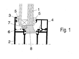
- FIG. 1 exemplifies a design, as is common in the art.
- this frame is provided for a filling element 1 in the form of a glazing, a panel or the like, wherein the filling element 1 is held at the edge between a fixed to the frame profile 2 stop bar 3 and a glass strip 4. Between the stop bar 3 and the glass strip 4 each have a sealing strip 5 is arranged.
- the filling element 1 is frontally supported at least in regions via an insertion profile 6 on the frame profile 2. This is done according to FIG. 1 So far, for example, a backfill 7 and a bond 8.
- the invention provides that the insertion profile 6 is adapted to receive a glued from the glazing bar 4 forth clamping profile 9, wherein the clamping profile 9 indirectly or directly closes the gap between the frame and filling element in the form of a pressure-resistant backfill and a contact pressure against the end face 1.1 of the filling element 1 is generated.
- FIG. 2 an embodiment is shown in which between the end face of the filling element 1 and the insertion profile 6 is provided for a glass bar 4 towards receiving pocket 11 for receiving the clamping profile 9.
- the insertion profile 6 is provided on its side facing the clamping profile 9 with a spreader 15 positively receiving teeth to prevent inadvertent or automatic release of the clamping profile 9.
- the clamping profile 9 is arranged with a centrally disposed between the spreading elements 15, parallel to the end face of the filling member 1 extending gap 16 which serves approximately for tolerances of the filling element for receiving a compensation insert.
- the insert profile 6 is, as is apparent from the drawing, held in a form-fitting frame profile 2, wherein in addition there is also the possibility of creating over profiled strips, for example, an undercut groove, given by the addition of a non-positive connection between the insertion profile 6 and the frame profile 2 is.
- the insert profile 6 may be provided with a Abrißsteg 13, arising from the FIGS. 2 and 3 results and which is otherwise removed in the embodiments of Figures 4 to 8, which can be a simple adaptability to different geometries of the frame profile 2 realize.
- the Figure: "3 shows a different, not belonging to the invention "embodiment, in which the insert profile 6 and the clamping profile 9 are integrally formed with each other .
- the clamping profile 9 is formed by spreading elements 15 which are directed obliquely to the frame profile 2.
- the embodiment allows a particularly simple and fast assembly.
- the insert profile 6 is provided on its side facing away from the glazing bar 4 with a leg 6.1 extending between the stop bar 3 and the filling element 1.
- leg 6.1 of the insertion profile 6 may have a perpendicular to the filling element 1 aligned receiving groove 14 into which a holding web of the building exterior sealing strip 5 engages. This makes it difficult to remove the outer seal.
- leg 6.1 of the insertion profile 6 is encompassed by an edge profile of the building exterior side sealing strip 5.
Landscapes
- Engineering & Computer Science (AREA)
- Civil Engineering (AREA)
- Structural Engineering (AREA)
- Securing Of Glass Panes Or The Like (AREA)
Description
- Die Erfindung betrifft einen einbruchhemmenden Rahmen, insbesondere für Fenster oder Türen, mit einem Füllelement in Form einer Verglasung, eines Paneels oder dergleichen, bei welchem das Füllelement randseitig zwischen einer am Rahmenprofil festgelegten Anschlagleiste und einer Glasleiste über dazwischenliegende Dichtleisten gehalten und stirnseitig zumindest bereichsweise über ein Einlegeprofil am Rahmen abgestützt ist, wobei das Einlegeprofil zur Aufnahme eines von der Glasleiste her einzusetzenden Klemmprofils eingerichtet ist, das den Spalt zwischen Rahmen und Füllelement in Form einer druckfesten Hinterfüllung schließt und mittelbar oder unmittelbar einen Anpreßdruck gegen die Stirnfläche des Füllelements erzeugt.
- Derartige Rahmen sind in vielfältigen Ausführungsformen aus der Praxis bekannt, wobei das Einlegeprofil häufig von einer zwischen dem Rahmen und dem Füllelement angeordneten Hinterfüllschnur sowie einer daran angrenzenden Verklebung gebildet ist. Dabei sind Ausführungsformen bekannt, bei welchen entweder die innenseitige oder auch die außenseitige Scheibe der aus Verbundsicherheitsglas bestehenden Verglasung verklebt sein kann.
- Die D1 beschreibt ein Rückhalteelement für ein Paneel, mit welchem mehrere näher aufgeführte Nachteil beseitigt werden sollen. Trotz entsprechender Hinweise ist der dort beschriebene Rahmen weit davon entfernt, als einbruchhemmend gelten zu können. Dies ergibt sich nicht schon daraus, daß die - lösbare - Glashalteleiste auf die - angriffsgefährdete - Außenseite gelegt ist. Daher kann - jedenfalls nach Entfernen der Glashalteleiste - ein unbefugtes Entfernen des Paneels nicht verhindert werden. Für den Fachmann beschreibt diese Schrift lediglich eine von vielen Möglichkeiten, eine Verklotzung des Panels vorzunehmen, wobei hier ein zusätzlicher seitlicher Halt durch den Clip gegeben ist. Eine wirksame Einbruchhemmung kann mit diesem vorbeschriebenen Rahmen nicht erreicht werden.
- Gleiches gilt für die
EP 0400374 A2 , deren Titel bereits ausdrücklich darauf hinweist, daß eine einfache Querverklotzung erreicht werden soll, ohne daß unerwünschte Spannungen in der Glasscheibe auftreten. Maßnahmen zur Einbruchsicherung mittels eines entsprechenden Anpressdrucks werden hier also ausdrücklich ausgeschlossen. - Bei der
DE 2044299 A handelt es sich um eine Diagonalverklotzung für Rahmen mit geringer Falzabmessung, bei der nach dem Aufsetzen des Glasleistenprofils eine Verstellung der Tragklötzchen verhindert werden soll. Diese Schrift spricht mit keinem Wortm eine Rahmenanordnung in einbruchhemmender Ausgestaltung an, die im übrigen in damaliger zeit noch eine völlig untergeordnete Rolle gespielt hat. - Auch die
DE 19956441 A1 befaßt sich ausschließlich mit der Verklotzung von Isolierglasscheiben, wozu ein - planparalleler - Richtklotz zwischen den Rahmen und eine Glaskantenschutzplatte eingeschoben wird. Hierzu wird ausdrücklich auf die Möglichkeit hingewiesen, den Klotz leicht wieder zum Zweck des Austauschs entfernen zu können, was einbruchhemmender Gestaltung gerade nicht erwünscht ist. - Bei dem mit einem Rahmenfüllelement versehenen Holzrahmen der
DE 29520518 U1 soll das Rahmenfüllelement durch die Verklotzungselemente so lange senkrecht zur Rahmenebene gesichert werden, bis die Abschlußleiste angebracht ist. Dazu sind Federglieder vorgesehen, die insbesondere auch Toleranzen und Spiel ausgleichen sollen, die beispielsweise von Schwund hervorgerufen sein können. Einbruchhemmende Maßnahmen sind hier weder vorgesehen noch auch nur andeutungsweise angesprochen. - Bei der Anordnung nach der
GB 2051197 A - Nachteilig bei einigen bekannten Ausführungsformen ist, daß die Verklebung einerseits einen hohen Fertigungsaufwand darstellt, wobei die Verarbeitung auf der Baustelle selbst nur bedingt möglich ist. Darüberhinaus erschwert die Verklebung einen ggf. notwendigen Austausch der Verglasung. Bekannt ist auch bereits eine Lösung, bei der ein Stahlwinkel das Füllelement hält, wobei der Stahlwinkel mit dem Rahmen vorzugsweise gebäudeinnenseitig verschraubt ist. Auch diese Ausgestaltung stellt jedoch einen erhöhten Fertigungsaufwand dar.
- Der Erfindung liegt daher die Aufgabe zugrunde, einen Rahmen der eingangs genannten Art so auszubilden, daß bei ausreichender einbruchshemmender Wirkung gleichwohl eine vereinfachte Montage möglich ist.
- Diese Aufgabe wird nach der Erfindung: "mit einem Rahmen nach dem vorliegenden Anspruch 1 gelöst, nämlich gemäß seinem kennzeichnenden Teil dadurch, daß" zwischen der Stirnfläche des Füllelements und dem Einlegeprofil eine zur Glasleiste hin offene Aufnahmetasche zur Aufnahme des Klemmprofils vorgesehen ist, dessen Wandflächen zur Glasleiste oder schräg zum Rahmenprofil hin gerichtete Spreizelemente tragen.
- Der durch die Erfindung erreichte Vorteil besteht im wesentlichen darin, daß die Montage durch einfaches Einschieben des Klemmprofils vorgenommen werden kann, wobei sich darüberhinaus der Vorteil ergibt, daß sich relativ große Maßtoleranzen an Scheiben und Rahmen kompensieren lassen.
- Um ein selbsttätiges Lösen des Klemmprofils zu verhindern, kann das Einlegeprofil auf seiner dem Klemmprofil zugewandten Seite mit einer die Spreizelemente formschlüssig aufnehmenden Verzahnung versehen sein. Hierbei kann das Klemmprofil mit einem mittig zwischen den Spreizelementen angeordneten, parallel zur Stirnfläche des Füllelements sich erstreckenden Spalt zur Aufnahme einer Ausgleichseinlage versehen sein, um Toleranzen des Füllelements einfach ausgleichen zu können.
- Das Einlegeprofil kann in bevorzugter Ausgestaltung auch mit einem lösbar angeschlossenen Abrißsteg versehen sein, der beispielsweise dem Isoliersteg des wärmegedämmten Verbundprofils anliegt. Bei Variationen in der Gestaltung des Rahmens besteht dann die Möglichkeit, den Abrißsteg zu entfernen, so daß ein einheitliches Einlegeprofil auch für unterschiedliche Gestaltungen des Rahmens einsetzbar ist.
- Weiter besteht im Rahmen der Erfindung die Möglichkeit, daß das Einlegeprofil auf seiner der Glasleiste abgewandten Seite mit einem sich zwischen die Anschlagleiste und das Füllelement erstreckenden Schenkel versehen ist.
- Weiter hat es sich als zweckmäßig herausgestellt, wenn der Schenkel des Einlegeprofils eine senkrecht zum Füllelement ausgerichtete Aufnahmenut für einen Haltesteg der gebäudeaußenseitigen Dichtleiste aufweist. Durch diese Gestaltung wird ein Lösen der Dichtleiste erschwert, wodurch ein Angriff auf den Rand des Füllelements bzw. den Rahmen zusätzlich behindert wird. Alternativ kann hierzu der Schenkel des Einlegeprofils auch von einem Randprofil der gebäudeaußenseitigen Dichtleiste umgriffen sein.
- Im folgenden wird die Erfindung an in der Zeichnung dargestellten Ausführungsbeispielen näher erläutert; es zeigen:
- Fig. 1
- beispielhaft eine Ausgestaltung nach dem Stand der Technik in ausschnittweiser Darstellung,
- Fig. 2
- eine Ausgestaltung der Erfindung in der
Fig. 1 entsprechender Darstellung, - Fig. 3
- eine weitere", nicht zur Erfindung gehörende Alternative" einer Gestaltung der Klemmleiste.
- Der in der Zeichnung nur teilweise im Querschnitt dargestellte Rahmen ist einbruchhemmend ausgebildet, wobei die
Figur 1 beispielhaft eine Gestaltung wiedergibt, wie sie im Stand der Technik üblich ist. Im einzelnen ist dieser Rahmen für ein Füllelement 1 in Form einer Verglasung, eines Paneels oder dergleichen vorgesehen, wobei das Füllelement 1 randseitig zwischen einer am Rahmenprofil 2 festgelegten Anschlagleiste 3 und einer Glasleiste 4 gehalten ist. Zwischen der Anschlagleiste 3 und der Glasleiste 4 ist jeweils eine Dichtleiste 5 angeordnet. Zusätzlich ist das Füllelement 1 stirnseitig zumindest bereichsweise über ein Einlegeprofil 6 am Rahmenprofil 2 abgestützt. Hierzu dient gemäßFigur 1 bisher beispielsweise eine Hinterfüllschnur 7 sowie eine Verklebung 8. - Derartige Verklebungen sind jedoch mit einem erhöhten Fertigungsaufwand verbunden, wobei darüber hinaus eine Verarbeitung auf der Baustelle selbst nur bedingt möglich ist. Im übrigen erschwert eine solche Verklebung einen gegebenenfalls notwendigen Austausch des Füllelements 1.
- Daher sieht die Erfindung vor, daß das Einlegeprofil 6 zur Aufnahme eines von der Glasleiste 4 her einzusetzenden Klemmprofils 9 eingerichtet ist, wobei das Klemmprofil 9 mittelbar oder unmittelbar den Spalt zwischen Rahmen und Füllelement in Form einer druckfesten Hinterfüllung schließt und einen Anpreßdruck gegen die Stirnfläche 1.1 des Füllelementes 1 erzeugt.
- In
Figur 2 ist eine Ausführungsform dargestellt, bei der zwischen der Stirnfläche des Füllelements 1 und dem Einlegeprofil 6 eine zur Glasleiste 4 hin offene Aufnahmetasche 11 zur Aufnahme des Klemmprofils 9 vorgesehen ist. Die Wandflächen des Klemmprofils 9 tragen zur Glasleiste 4 hin gerichtete Spreizelemente 15. Zusätzlich ist das Einlegeprofil 6 auf seiner dem Klemmprofil 9 zugewandten Seite mit einer die Spreizelemente 15 formschlüssig aufnehmenden Verzahnung versehen, um ein unbeabsichtigtes bzw. selbsttätiges Lösen des Klemmprofils 9 zu vermeiden. Weiter ist das Klemmprofil 9 mit einem mittig zwischen den Spreizelementen 15 angeordneten, parallel zur Stirnfläche des Füllelements 1 sich erstreckenden Spalt 16 versehen, der etwa bei Toleranzen des Füllelements zur Aufnahme einer Ausgleichseinlage dient. - Das Einlegeprofil 6 ist, wie sich aus der Zeichnung ergibt, formschlüssig im Rahmenprofil 2 gehalten, wobei zusätzlich auch die Möglichkeit besteht, über Profilleisten beispielsweise eine hinterschnittene Nut zu schaffen, durch die zusätzlich der eine kraftschlüssige Verbindung zwischen dem Einlegeprofil 6 und dem Rahmenprofil 2 gegeben ist. Auch kann das Einlegeprofil 6 mit einem Abrißsteg 13 versehen sein, der sich aus den
Figuren 2 und 3 ergibt und der im übrigen bei den Ausgestaltungen nach den Figuren 4 bis 8 entfernt ist, wodurch sich eine einfache Anpaßbarkeit an unterschiedliche Geometrien des Rahmenprofils 2 realisieren läßt. - Die
Figur : " 3 zeigt eine abweichende, nicht zur Erfindung gehörende" Ausgestaltung, bei der das Einlegeprofil 6 und das Klemmprofil 9 einstückig miteinander ausgebildet sind. Das Klemmprofil 9 ist dabei von Spreizelementen 15 gebildet, die schräg zum Rahmenprofil 2 hin gerichtet sind. Die Ausführungsform erlaubt eine besonders einfache und schnelle Montage. - Um einen Angriff auf den Rahmen von der Gebäudeaußenseite her zusätzlich zu erschweren, besteht die Möglichkeit, daß das Einlegeprofil 6 auf seiner der Glasleiste 4 abgewandten Seite mit einem sich zwischen die Anschlagleiste 3 und das Füllelement 1 erstreckenden Schenkel 6.1 versehen ist.
- Zusätzlich kann dann der Schenkel 6.1 des Einlegeprofils 6 eine senkrecht zum Füllelement 1 ausgerichtete Aufnahmenut 14 aufweisen, in die ein Haltesteg der gebäudeaußenseitigen Dichtleiste 5 eingreift. Hierdurch wird die Entfernung der Außendichtung erschwert.
- Alternativ kann dies jedoch auch dadurch erreicht werden, daß der Schenkel 6.1 des Einlegeprofils 6 von einem Randprofil der gebäudeaußenseitigen Dichtleiste 5 umgriffen wird.
Claims (8)
- Einbruchhemmender Rahmen, insbesondere für Fenster oder Türen, mit einem Füllelement (1) in Form einer Verglasung, eines Paneels oder dergleichen, bei welchem das Füllelement (1) randseitig zwischen einer am Rahmenprofil (2) festgelegten Anschlagleiste (3) und einer Glasleiste (4) über dazwischenliegende Dichtleisten (5) gehalten und stirnseitig zumindest bereichsweise über ein Einlegeprofil (6) am Rahmen abgestützt ist, wobei das Einlegeprofil (6) zur Aufnahme eines von der Glasleiste (4) her einzusetzenden Klemmprofils (9) eingerichtet ist, wobei das Klemmprofil (9) den Spalt zwischen Rahmen und Füllelement in Form einer druckfesten Hinterfüllung schließt und mittelbar oder unmittelbar einen Anpreßdruck gegen die Stirnfläche des Füllelements (1) erzeugt, dadurch gekennzeichnet, daß zwischen der Stirnfläche des Füllelements (1) und dem Einlegeprofil (6) eine zur Glasleiste (4) hin offene Aufnahmetasche (11) zur Aufnahme des Klemmprofils (9) vorgesehen ist, dessen Wandflächen zur Glasleiste (4) oder schräg zum Rahmenprofil (2) hin gerichtete Spreizelemente (15) tragen.
- Rahmen nach Anspruch 1, dadurch gekennzeichnet, daß das Einlegeprofil (6) auf seiner dem Klemmprofil (9) zugewandten Seite mit einer die Spreizelemente (15) formschlüssig aufnehmenden Verzahnung versehen ist.
- Rahmen nach Anspruch 1 oder 2, dadurch gekennzeichnet, daß das Klemmprofil (9) mit einem mittig zwischen den Spreizelementen (15) angeordneten, parallel zur Stirnfläche des Füllelements (1) sich erstreckenden Spalt (16) zur Aufnahme einer Ausgleichseinlage versehen ist.
- Rahmen nach einem der Ansprüche 1 bis 3, dadurch gekennzeichnet, daß das Einlegeprofil (6) formschlüssig im Rahmenprofil (2) gehalten ist.
- Rahmen nach einem der Ansprüche 1 bis 4, dadurch gekennzeichnet, daß das Einlegeprofil (6) mit einem lösbar angeschlossenen Abrißsteg (13) versehen ist, der dem Isoliersteg eines wärmegedämmten Verbundprofils anliegt.
- Rahmen nach einem der Ansprüche 1 bis 5, dadurch gekennzeichnet, daß das Einlegeprofil (6) auf seiner der Glasleiste (4) abgewandten Seite mit einem sich zwischen die Anschlagleiste (3) und das Füllelement (1) erstreckenden Schenkel (6.1) versehen ist.
- Rahmen nach einem der Ansprüche 1 bis 6, dadurch gekennzeichnet, daß der Schenkel (6.1) des Einlegeprofils (6) eine senkrecht zum Füllelement (1) ausgerichtete Aufnahmenut (14) für einen Haltesteg der gebäudeaußenseitigen Dichtleiste (5) aufweist.
- Rahmen nach einem der Ansprüche 1 bis 7, dadurch gekennzeichnet, daß der Schenkel (6.1) des Einlegeprofils (6) von einem Randprofil der gebäudeaußenseitigen Dichtleiste (5) umgriffen ist.
Applications Claiming Priority (2)
| Application Number | Priority Date | Filing Date | Title |
|---|---|---|---|
| DE2001145616 DE10145616A1 (de) | 2001-09-15 | 2001-09-15 | Einbruchhemmender Rahmen |
| DE10145616 | 2001-09-15 |
Publications (3)
| Publication Number | Publication Date |
|---|---|
| EP1293639A2 EP1293639A2 (de) | 2003-03-19 |
| EP1293639A3 EP1293639A3 (de) | 2004-01-07 |
| EP1293639B1 true EP1293639B1 (de) | 2015-05-27 |
Family
ID=7699211
Family Applications (1)
| Application Number | Title | Priority Date | Filing Date |
|---|---|---|---|
| EP02020623.1A Expired - Lifetime EP1293639B1 (de) | 2001-09-15 | 2002-09-13 | Einbruchhemmender Rahmen |
Country Status (2)
| Country | Link |
|---|---|
| EP (1) | EP1293639B1 (de) |
| DE (1) | DE10145616A1 (de) |
Families Citing this family (14)
| Publication number | Priority date | Publication date | Assignee | Title |
|---|---|---|---|---|
| DE102004055800A1 (de) * | 2004-11-18 | 2006-05-24 | Aluplast Gmbh | Flügel für ein Fenster oder eine Tür |
| DE202005004616U1 (de) * | 2005-03-22 | 2006-04-27 | Rehau Ag + Co. | Tür- bzw. Fensterelement |
| DE202005011059U1 (de) * | 2005-07-13 | 2006-11-23 | Salamander Industrie-Produkte Gmbh | Flügel für ein Fenster oder eine Tür |
| DE102006038950A1 (de) * | 2006-08-18 | 2008-02-21 | Klaus Knaust | Doppelkeilverklotzung für Fensterflügel |
| DE102006061655A1 (de) * | 2006-10-13 | 2008-04-17 | Raico Bautechnik Gmbh | Wärmedämmleiste |
| GB2451468B (en) * | 2007-07-28 | 2011-12-07 | Glazpart Holdings Ltd | A retaining device for a glazed unit |
| DE102012107574A1 (de) * | 2012-08-17 | 2014-02-20 | SCHÜCO International KG | Rahmen für ein Fenster und Isolierelement |
| PT2909410T (pt) | 2012-08-29 | 2023-11-22 | Soudal | Isolamento de janela melhorado |
| DE202013100101U1 (de) * | 2013-01-10 | 2013-02-22 | SCHÜCO International KG | Wärmedämmleiste und Rahmenprofil für ein Fenster, eine Tür, eine Fassade oder ein Lichtdach |
| DE102013107175B4 (de) * | 2013-07-08 | 2021-11-11 | Pax Ag | Verschlusselement mit einem Klemmelement |
| GB2548605B (en) * | 2016-03-23 | 2021-03-31 | Hocking Steven | A clip assembly |
| DE102017100552A1 (de) * | 2017-01-04 | 2018-07-05 | Hörmann KG Eckelhausen | Gebäudeabschlusselement und Verfahren zur Montage desselben |
| FR3079549A1 (fr) * | 2018-03-29 | 2019-10-04 | Atrya | Element de fermeture de baie et son procede de fabrication |
| DE202019106654U1 (de) * | 2019-11-29 | 2021-03-02 | Rehau Ag + Co | Fenster- oder Türflügel sowie diesen umfassende(s) Fenster oder Tür |
Family Cites Families (8)
| Publication number | Priority date | Publication date | Assignee | Title |
|---|---|---|---|---|
| DE7525175U (de) * | 1975-12-11 | Fleischer G | Scheibenklemm-Element aus Kunststoff | |
| GB2051197A (en) * | 1979-06-13 | 1981-01-14 | Blacknell Buildings Ltd | Window Mounting Assembly |
| DE8906547U1 (de) * | 1989-05-27 | 1989-07-27 | Niemann, Hans Dieter, 5014 Kerpen | Einrichtung zur Verklotzung von Scheiben in Tür- oder Fensterrahmen |
| US5036637A (en) * | 1989-11-01 | 1991-08-06 | Butler Manufacturing Corporation | Rolled metal building system |
| GB9424555D0 (en) * | 1994-12-06 | 1995-01-25 | Chattin Peter J | Retention device |
| DE29520518U1 (de) * | 1995-12-23 | 1996-03-07 | Kretschmer, Cornelia, 89231 Neu-Ulm | Holzrahmen und Rahmenfüllelement |
| DE29905777U1 (de) * | 1999-03-30 | 1999-06-17 | Dyna Fenster & Türen GmbH, 55481 Kirchberg | Einbruchhemmendes Fenster oder einbruchhemmende Tür |
| DE19956441A1 (de) * | 1999-11-24 | 2001-05-31 | Werner Schmitz | Vorrichtung zum Verklotzen von Isolierglasscheiben |
-
2001
- 2001-09-15 DE DE2001145616 patent/DE10145616A1/de not_active Withdrawn
-
2002
- 2002-09-13 EP EP02020623.1A patent/EP1293639B1/de not_active Expired - Lifetime
Also Published As
| Publication number | Publication date |
|---|---|
| EP1293639A3 (de) | 2004-01-07 |
| EP1293639A2 (de) | 2003-03-19 |
| DE10145616A1 (de) | 2003-04-17 |
Similar Documents
| Publication | Publication Date | Title |
|---|---|---|
| DE3714629C2 (de) | Fassadenwand eines Gebäudes | |
| EP3423658B1 (de) | Tür, fenster oder fassadenelement | |
| DE2059829A1 (de) | Struktursystem fuer den Zusammenbau von vorgefertigten Konstruktionen | |
| EP1293639A2 (de) | Einbruchhemmender Rahmen | |
| EP2666948A1 (de) | Rahmenanordnung für ein Sektionaltorpaneel | |
| AT392311B (de) | Rahmenkonstruktion in pfosten-riegel-bauweise, insbesondere fuer fassaden, daecher, fensterwaende od. dgl. | |
| AT14257U1 (de) | Isolierglasscheibe | |
| EP2594724B1 (de) | Einbruchhemmende Tür oder einbruchhemmendes Fenster | |
| EP1288426A2 (de) | Sicherheitsglasfalzeinlage/Sicherheitsverglasungsklotz | |
| DE20119725U1 (de) | Sicherungsvorrichtung zum Sichern eines geschlossenen Tür- und/oder Fensterflügels, Sicherungsprofil für eine solche Sicherungsvorrichtung sowie Gebäudeschiebetür oder Gebäudeschiebefenster mit einer solchen Sicherungsvorrichtung | |
| DE9104769U1 (de) | Haltevorrichtung | |
| DE102013107175B4 (de) | Verschlusselement mit einem Klemmelement | |
| DE202017106284U1 (de) | Festverglasungssystem zur Fixierung einer Glashalteleiste mit definierbarem Anpressdruck | |
| EP0550841A2 (de) | Fassadenkonstruktion | |
| DE10054175A1 (de) | Einbruchhemmende Fensterkonstruktion | |
| DE20118507U1 (de) | Haustür | |
| DE20100618U1 (de) | Rahmenprofil | |
| EP0823014B1 (de) | Rahmenlose glastür | |
| EP1061194A2 (de) | Haltevorrichtung für Glasscheiben | |
| DE8809818U1 (de) | Einbruchssicheres Fenster | |
| DE102014005717A1 (de) | Tragkonstruktion für Geländer und Geländer mit einer solchen Tragkonstruktion | |
| EP2314817B1 (de) | Schallschutztür | |
| EP0607866A2 (de) | Füllelement-Halterung für Fassadenelemente, Fenster, Türen oder dergleichen | |
| DE102017108587A1 (de) | Verbundfenster sowie Kombi-Glashalter hierfür | |
| DE3528388A1 (de) | Elastische profildichtung fuer isolierverglasungen |
Legal Events
| Date | Code | Title | Description |
|---|---|---|---|
| PUAI | Public reference made under article 153(3) epc to a published international application that has entered the european phase |
Free format text: ORIGINAL CODE: 0009012 |
|
| AK | Designated contracting states |
Designated state(s): AT BE BG CH CY CZ DE DK EE ES FI FR GB GR IE IT LI LU MC NL PT SE SK TR Kind code of ref document: A2 Designated state(s): AT BE BG CH CY CZ DE DK EE ES FI FR GB GR IE IT LI LU MC NL PT SE SK TR |
|
| AX | Request for extension of the european patent |
Extension state: AL LT LV MK RO SI |
|
| PUAL | Search report despatched |
Free format text: ORIGINAL CODE: 0009013 |
|
| AK | Designated contracting states |
Kind code of ref document: A3 Designated state(s): AT BE BG CH CY CZ DE DK EE ES FI FR GB GR IE IT LI LU MC NL PT SE SK TR |
|
| AX | Request for extension of the european patent |
Extension state: AL LT LV MK RO SI |
|
| 17P | Request for examination filed |
Effective date: 20040108 |
|
| AKX | Designation fees paid |
Designated state(s): AT BE BG CH CY CZ DE DK EE ES FI FR GB GR IE IT LI LU MC NL PT SE SK TR |
|
| 17Q | First examination report despatched |
Effective date: 20061218 |
|
| RAP1 | Party data changed (applicant data changed or rights of an application transferred) |
Owner name: SAPA AS |
|
| GRAP | Despatch of communication of intention to grant a patent |
Free format text: ORIGINAL CODE: EPIDOSNIGR1 |
|
| INTG | Intention to grant announced |
Effective date: 20150105 |
|
| GRAS | Grant fee paid |
Free format text: ORIGINAL CODE: EPIDOSNIGR3 |
|
| GRAA | (expected) grant |
Free format text: ORIGINAL CODE: 0009210 |
|
| AK | Designated contracting states |
Kind code of ref document: B1 Designated state(s): AT BE BG CH CY CZ DE DK EE ES FI FR GB GR IE IT LI LU MC NL PT SE SK TR |
|
| REG | Reference to a national code |
Ref country code: GB Ref legal event code: FG4D Free format text: NOT ENGLISH |
|
| REG | Reference to a national code |
Ref country code: CH Ref legal event code: EP |
|
| REG | Reference to a national code |
Ref country code: AT Ref legal event code: REF Ref document number: 728967 Country of ref document: AT Kind code of ref document: T Effective date: 20150615 |
|
| REG | Reference to a national code |
Ref country code: IE Ref legal event code: FG4D Free format text: LANGUAGE OF EP DOCUMENT: GERMAN |
|
| REG | Reference to a national code |
Ref country code: DE Ref legal event code: R096 Ref document number: 50216054 Country of ref document: DE Effective date: 20150709 |
|
| PG25 | Lapsed in a contracting state [announced via postgrant information from national office to epo] |
Ref country code: FI Free format text: LAPSE BECAUSE OF FAILURE TO SUBMIT A TRANSLATION OF THE DESCRIPTION OR TO PAY THE FEE WITHIN THE PRESCRIBED TIME-LIMIT Effective date: 20150527 Ref country code: PT Free format text: LAPSE BECAUSE OF FAILURE TO SUBMIT A TRANSLATION OF THE DESCRIPTION OR TO PAY THE FEE WITHIN THE PRESCRIBED TIME-LIMIT Effective date: 20150928 Ref country code: ES Free format text: LAPSE BECAUSE OF FAILURE TO SUBMIT A TRANSLATION OF THE DESCRIPTION OR TO PAY THE FEE WITHIN THE PRESCRIBED TIME-LIMIT Effective date: 20150527 |
|
| REG | Reference to a national code |
Ref country code: NL Ref legal event code: MP Effective date: 20150527 |
|
| PG25 | Lapsed in a contracting state [announced via postgrant information from national office to epo] |
Ref country code: GR Free format text: LAPSE BECAUSE OF FAILURE TO SUBMIT A TRANSLATION OF THE DESCRIPTION OR TO PAY THE FEE WITHIN THE PRESCRIBED TIME-LIMIT Effective date: 20150828 Ref country code: BG Free format text: LAPSE BECAUSE OF FAILURE TO SUBMIT A TRANSLATION OF THE DESCRIPTION OR TO PAY THE FEE WITHIN THE PRESCRIBED TIME-LIMIT Effective date: 20150827 |
|
| PG25 | Lapsed in a contracting state [announced via postgrant information from national office to epo] |
Ref country code: EE Free format text: LAPSE BECAUSE OF FAILURE TO SUBMIT A TRANSLATION OF THE DESCRIPTION OR TO PAY THE FEE WITHIN THE PRESCRIBED TIME-LIMIT Effective date: 20150527 Ref country code: DK Free format text: LAPSE BECAUSE OF FAILURE TO SUBMIT A TRANSLATION OF THE DESCRIPTION OR TO PAY THE FEE WITHIN THE PRESCRIBED TIME-LIMIT Effective date: 20150527 |
|
| PG25 | Lapsed in a contracting state [announced via postgrant information from national office to epo] |
Ref country code: SK Free format text: LAPSE BECAUSE OF FAILURE TO SUBMIT A TRANSLATION OF THE DESCRIPTION OR TO PAY THE FEE WITHIN THE PRESCRIBED TIME-LIMIT Effective date: 20150527 Ref country code: CZ Free format text: LAPSE BECAUSE OF FAILURE TO SUBMIT A TRANSLATION OF THE DESCRIPTION OR TO PAY THE FEE WITHIN THE PRESCRIBED TIME-LIMIT Effective date: 20150527 |
|
| REG | Reference to a national code |
Ref country code: DE Ref legal event code: R097 Ref document number: 50216054 Country of ref document: DE |
|
| PLBE | No opposition filed within time limit |
Free format text: ORIGINAL CODE: 0009261 |
|
| REG | Reference to a national code |
Ref country code: DE Ref legal event code: R119 Ref document number: 50216054 Country of ref document: DE |
|
| STAA | Information on the status of an ep patent application or granted ep patent |
Free format text: STATUS: NO OPPOSITION FILED WITHIN TIME LIMIT |
|
| PG25 | Lapsed in a contracting state [announced via postgrant information from national office to epo] |
Ref country code: MC Free format text: LAPSE BECAUSE OF FAILURE TO SUBMIT A TRANSLATION OF THE DESCRIPTION OR TO PAY THE FEE WITHIN THE PRESCRIBED TIME-LIMIT Effective date: 20150527 Ref country code: LU Free format text: LAPSE BECAUSE OF FAILURE TO SUBMIT A TRANSLATION OF THE DESCRIPTION OR TO PAY THE FEE WITHIN THE PRESCRIBED TIME-LIMIT Effective date: 20150913 Ref country code: IT Free format text: LAPSE BECAUSE OF FAILURE TO SUBMIT A TRANSLATION OF THE DESCRIPTION OR TO PAY THE FEE WITHIN THE PRESCRIBED TIME-LIMIT Effective date: 20150527 |
|
| REG | Reference to a national code |
Ref country code: CH Ref legal event code: PL |
|
| 26N | No opposition filed |
Effective date: 20160301 |
|
| GBPC | Gb: european patent ceased through non-payment of renewal fee |
Effective date: 20150913 |
|
| REG | Reference to a national code |
Ref country code: IE Ref legal event code: MM4A |
|
| REG | Reference to a national code |
Ref country code: FR Ref legal event code: ST Effective date: 20160531 |
|
| PG25 | Lapsed in a contracting state [announced via postgrant information from national office to epo] |
Ref country code: LI Free format text: LAPSE BECAUSE OF NON-PAYMENT OF DUE FEES Effective date: 20150930 Ref country code: IE Free format text: LAPSE BECAUSE OF NON-PAYMENT OF DUE FEES Effective date: 20150913 Ref country code: DE Free format text: LAPSE BECAUSE OF NON-PAYMENT OF DUE FEES Effective date: 20160401 Ref country code: GB Free format text: LAPSE BECAUSE OF NON-PAYMENT OF DUE FEES Effective date: 20150913 Ref country code: CH Free format text: LAPSE BECAUSE OF NON-PAYMENT OF DUE FEES Effective date: 20150930 |
|
| PG25 | Lapsed in a contracting state [announced via postgrant information from national office to epo] |
Ref country code: FR Free format text: LAPSE BECAUSE OF NON-PAYMENT OF DUE FEES Effective date: 20150930 |
|
| REG | Reference to a national code |
Ref country code: AT Ref legal event code: MM01 Ref document number: 728967 Country of ref document: AT Kind code of ref document: T Effective date: 20150913 |
|
| PG25 | Lapsed in a contracting state [announced via postgrant information from national office to epo] |
Ref country code: AT Free format text: LAPSE BECAUSE OF NON-PAYMENT OF DUE FEES Effective date: 20150913 |
|
| PG25 | Lapsed in a contracting state [announced via postgrant information from national office to epo] |
Ref country code: NL Free format text: LAPSE BECAUSE OF FAILURE TO SUBMIT A TRANSLATION OF THE DESCRIPTION OR TO PAY THE FEE WITHIN THE PRESCRIBED TIME-LIMIT Effective date: 20150527 Ref country code: SE Free format text: LAPSE BECAUSE OF FAILURE TO SUBMIT A TRANSLATION OF THE DESCRIPTION OR TO PAY THE FEE WITHIN THE PRESCRIBED TIME-LIMIT Effective date: 20150527 Ref country code: CY Free format text: LAPSE BECAUSE OF FAILURE TO SUBMIT A TRANSLATION OF THE DESCRIPTION OR TO PAY THE FEE WITHIN THE PRESCRIBED TIME-LIMIT Effective date: 20150527 |
|
| PG25 | Lapsed in a contracting state [announced via postgrant information from national office to epo] |
Ref country code: BE Free format text: LAPSE BECAUSE OF NON-PAYMENT OF DUE FEES Effective date: 20150930 |
|
| PG25 | Lapsed in a contracting state [announced via postgrant information from national office to epo] |
Ref country code: TR Free format text: LAPSE BECAUSE OF FAILURE TO SUBMIT A TRANSLATION OF THE DESCRIPTION OR TO PAY THE FEE WITHIN THE PRESCRIBED TIME-LIMIT Effective date: 20150527 |