EP1293420A2 - Durch eine Steuerkurve gesteuerter Hubtisch - Google Patents
Durch eine Steuerkurve gesteuerter Hubtisch Download PDFInfo
- Publication number
- EP1293420A2 EP1293420A2 EP02020338A EP02020338A EP1293420A2 EP 1293420 A2 EP1293420 A2 EP 1293420A2 EP 02020338 A EP02020338 A EP 02020338A EP 02020338 A EP02020338 A EP 02020338A EP 1293420 A2 EP1293420 A2 EP 1293420A2
- Authority
- EP
- European Patent Office
- Prior art keywords
- lifting
- control curve
- control
- frame
- lifting frame
- Prior art date
- Legal status (The legal status is an assumption and is not a legal conclusion. Google has not performed a legal analysis and makes no representation as to the accuracy of the status listed.)
- Granted
Links
Images

Classifications
-
- B—PERFORMING OPERATIONS; TRANSPORTING
- B62—LAND VEHICLES FOR TRAVELLING OTHERWISE THAN ON RAILS
- B62D—MOTOR VEHICLES; TRAILERS
- B62D65/00—Designing, manufacturing, e.g. assembling, facilitating disassembly, or structurally modifying motor vehicles or trailers, not otherwise provided for
- B62D65/02—Joining sub-units or components to, or positioning sub-units or components with respect to, body shell or other sub-units or components
Definitions
- the invention relates to a device for controlling mobile lifting tables, such as those used in the automotive industry become.
- skids In the automotive industry, vehicles are becoming continuous transported by the bodies on a skid or self-propelled lifting table are arranged. These skids will be in a queue either pushed or pointed have their own drive and follow so-called paths in the Factory buildings.
- a mounting system for automobiles is known from the publication DE 4004853 known that runs on rollers and a lifting and tilting device includes.
- the tilt and lift drive takes place by means of an electric drive that uses energy to make contact is supplied.
- using contact traces leads to a number of Problems such as employee protection, wear and tear, and contact problems.
- a method and a are known from the publication DE 4002414 A1 Device for transporting objects along a production line known, with a control rail arranged in parallel and aligns the pallet truck horizontally.
- the object of the invention is to provide a device which is independently rolling and whose stroke by one simple mechanical mechanism is controlled. Farther the stroke should be flexible and take place using space-saving means.
- skids mobile lifting tables
- This drive is an electric motor that runs through Sliding contacts are powered.
- the roles are regular attached to a base frame.
- a lifting frame is arranged, preferably via lifting elements in the form of lifting scissors, connected to the base frame is.
- a lifting shear enables a simple and stable mechanical lifting. Through a guide element that is below the lifting frame is arranged and that by one on one Ground-mounted control curve is deflected, the Lift table aligned.
- other modules use that are deflected on a horizontal plane. These can e.g. B. over chains or other drives with the be provided for the lifting assembly.
- the energy absorbed by the guide element is transferred by further Means, which are preferably mechanical, in a lifting energy converted.
- the toggle lever projects a control roller in connection with the control cam.
- two, preferably parallel guiding elements below the lifting frame are arranged and secured by two on the floor Control curves are used.
- the control curves are arranged in mirror image, the The mirror point lies between the two control curves.
- Another component of the present invention is Control curve using a mounting grid on the Ground is attached. This grid that between ground and Control curve is arranged, allows the variable arrangement and easy positioning of the control curve.
- the mounting grid has a large number of symmetrically arranged bores on.
- the mechanical positive guidance of the guide elements makes it in Difficult in individual cases to remove the skids from the lead, or to prevent the lifting function.
- control curve has insertable and removable segments on by a, preferably mechanical, guide can be inserted and removed.
- the leadership is trained that they’re manually powered by a motor Pneumatic drive or a hydraulic drive is controlled.
- the segments are thus guided out of the control curve removed that the control rollers made no contact in this area with the control curve.
- This tour can be a Be rail, preferably at a right angle to Control curve is arranged and on which the segment of the control curve is slidably disposed.
- the segment of the control curve can however also be designed such that only the side walls, which contacts the control roller, can be folded down. As a rule, a hinge is used for this, that the folding allows.
- the removable and insertable segments of the control curve are arranged in one embodiment so that the guide element the lifting table in the rest position with the segment open is not deflected.
- the lift table thus slides over one Distance without the lifting frame moving up or down becomes.
- Another component of the present invention is a full production line that includes one or more of the has mobile lifting tables, and by the invention Control curves can be controlled.
- FIG. 1 shows a skid 10, which is shown schematically with Rollers 25, with a base frame 11 and a lifting frame 12, which are connected to one another via lifting scissors 17 is. Furthermore, a toggle lever 15 is at its apex 13 hinged to the base frame 11.
- the toggle lever 15 is below arranged of the base frame and has at one end a control roller 16 and at its other end it is connected to a handlebar 18, which in turn with the power lever 22 is in contact.
- the power lever has three Joints on, with a hinge attached to the lifting frame, the second joint is connected to the handlebar 18 and the third Joint is connected to a lever element 21, which in turn communicates with the lifting frame. Through the lever element 21 becomes an even distribution of the force on the lifting frame ensured.
- the figure shows the corresponding arrow schematic movement of the power lever and his Lever element as well as the scissors when the lifting frame is on Raised due to the change in the position of the toggle lever becomes.
- the toggle levers are via two links 18 with the help of an articulated bearing 19 connected to the power lever 22.
- FIG. 2 shows the structure of control curves, which is a control curve for a skid with only one toggle lever.
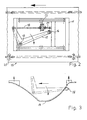
- FIG. 3 shows removable and insertable control curve segments which are identified by arrows and which are arranged at the beginning and at the end of an extended deflection. Should a guide remove the cam segments from their original position, the control roller 16 is not deflected and simply runs through the opening channel.
- the control cam segments are preferably moved on their guidance by a spindle drive. However, it is also conceivable to move the cam segments manually from their standard position using a lever. It is pointed out that other drives are also conceivable.
- the Control curves can be attached variably at adjustable intervals.
- the fastening grid preferably has a large number of holes or elongated holes that are used to attach the Control curve serve. So there is no direct contact with the floor, making simple adjustments possible without to carry out large drilling work.
Abstract
Description
- Fig. 1
- die Seitenansicht eines Skids mit einem Grundrahmen und einem Hubrahmen, wobei der Skid auf Rollen gelagert ist,
- Fig. 1a
- die Draufsicht auf einen Skid, der zwei parallel angeordnete Kniehebel aufweist, die am Grundrahmen angelenkt sind, und die über Lenker und ein Gelenklager mit dem Kraftumlenkhebel verbunden sind;
- Fig. 2
- die Draufsicht auf einen Skid, der nur einen Kniehebel umfasst, wobei der Kniehebel am Grundrahmen befestigt ist und über ein Lenkerelement mit dem Kraftumlenkhebel verbunden ist;
- Fig. 3
- eine Draufsicht auf die Steuerkurven sowie ihre variable Befestigung und den möglichen Verlauf der Steuerrollen sowie des entsprechenden Kniehebels;
Die Figur 3 zeigt den Aufbau von Steuerkurven, wobei es sich um eine Steuerkurve für einen Skid mit lediglich einem Kniehebel handelt. Weiterhin sind der Figur 3, durch Pfeile gekennzeichnete, entfernbare und einfügbare Steuerkurvensegmente zu entnehmen, die am Anfang und am Ende einer ausgedehnten Auslenkung angeordnet sind. Sollte eine Führung die Steuerkurvensegmente aus ihrer ursprünglichen Position entfernen, so wird die Steuerrolle 16 nicht ausgelenkt und läuft einfach durch den sich öffnenden Kanal. Die Steuerkurvensegmente werden auf ihrer Führung vorzugsweise durch einen Spindelantrieb bewegt. Es ist jedoch auch denkbar, die Steuerkurvensegmente manuell mit Hilfe eines Hebels aus ihrer Standardposition zu bewegen. Es wird darauf hingewiesen, dass andere Antriebe ebenfalls vorstellbar sind.
- 10
- Skid, fahrbare Plattform
- 11
- Grundrahmen
- 12
- Hubrahmen
- 13
- Scheitelpunkt
- 14
- Steuerkurve
- 15
- Kniehebel
- 16
- Steuerrolle
- 17
- Hubschere
- 18
- Lenker
- 19
- Gelenklager
- 20 21
- Hebelelement
- 22
- Kraftumlenkhebel
- 23 24 25
- Rollen
Claims (14)
- Hubtisch mit Rollen, insbesondere ein Skid für die Automobilindustrie, mit einem Grundrahmen und einem Hubrahmen, der über Hubelemente, insbesondere eine Hubschere, mit dem Grundrahmen verbunden ist, dadurch gekennzeichnet, dass über ein horizontal auslenkbares Führungselement (15), das durch eine auf einem Boden befestigte Steuerkurve (14) auf einer horizontalen Ebene auslenkbar ist, weitere mechanische Mittel (16, 18, 21, 22) so gesteuert werden, dass der Hubrahmen (12) in Abhängigkeit von der horizontalen Auslenkung des Führungselementes (15) gehoben und/oder gesenkt wird.
- Hubtisch nach dem vorhergehenden Anspruch, dadurch gekennzeichnet, dass das horizontal auslenkbare Führungselement unterhalb des Hubrahmens angeordnet ist.
- Hubtisch nach einem oder mehreren der vorhergehenden Ansprüche, dadurch gekennzeichnet, dass das Führungselement ein Kniehebel (15) ist, der über eine Steuerrolle (16) mit der Steuerkurve (14) in Wirkverbindung steht, um den Hubrahmen (12) über weitere Mittel (16, 18, 21, 22) auszurichten.
- Hubtisch nach einem oder mehreren der vorhergehenden Ansprüche, dadurch gekennzeichnet, dass der Kniehebel (15) am Grundrahmen (11) angelenkt ist und über einen Lenker (18) und einen Kraftumlenkhebel (22) mit dem Hubrahmen (12) verbunden ist.
- Hubtisch nach einem oder mehreren der vorhergehenden Ansprüche, gekennzeichnet durch zwei, die unterhalb des Hubrahmens angeordnet sind, und die durch zwei auf dem Boden befestigte Steuerkurven (14) auslenkbar sind.
- Hubtisch nach dem vorhergehenden Anspruch, dadurch gekennzeichnet, dass die Führungselemente über weitere mechanische Mittel (16, 18, 21, 22, 19) auf einen gemeinsamen Kraftumlenkhebel (22) wirken.
- Hubtisch nach einem oder mehreren der vorhergehenden Ansprüche, dadurch gekennzeichnet, dass der Kraftumlenkhebel (22) so ausgebildet ist, dass er die Kräfte des durch die Steuerkurve ausgelenkten Kniehebels (15) ausgewogen auf den Hubrahmen (12) verteilt.
- Steuerkurve zur Steuerung eines Hubrahmens, der Bestandteil eines Hubtisches nach einem oder mehreren der vorhergehenden Hubtischansprüche ist, dadurch gekennzeichnet, dass ein Befestigungsraster zwischen Steuerkurve (14) und Boden angeordnet ist, das eine variable Befestigung der Steuerkurve (14) mit dem Befestigungsraster ermöglicht.
- Steuerkurve nach dem vorhergehenden Anspruch, dadurch gekennzeichnet, dass das Befestigungsraster eine Vielzahl von symmetrisch angeordneten Bohrungen aufweist.
- Steuerkurve zur Steuerung eines Hubrahmens, der Bestandteil eines Hubtisches nach einem oder mehreren der vorhergehenden Hubtischansprüche ist, gekennzeichnet durch einfügbare und entfernbare Segmente in der Steuerkurve, die durch eine Führung eingefügt und entfernt werden können.
- Steuerkurve nach dem vorhergehenden Anspruch, dadurch gekennzeichnet, dass die Führung so ausgebildet ist, dass sie manuell, durch einen Motorantrieb, einen Pneumatikantrieb oder einen Hydraulikantrieb steuerbar ist.
- Steuerkurve nach einem oder mehreren der vorhergehenden Steuerkurvenansprüche, dadurch gekennzeichnet, dass die entfernbaren und einfügbaren Segmente der Steuerkurve so angeordnet sind, dass Führungselemente (15) des Hubtisches in der Ruheposition bei geöffnetem Segment nicht ausgelenkt werden.
- Fertigungsstraße, insbesondere für die Produktion von Kraftfahrzeugen, gekennzeichnet durch einen oder mehrere der fahrbaren Hubtische nach einem oder mehreren der vorhergehenden Hubtischansprüchen.
- Fertigungsstraße nach dem vorhergehenden Fertigungsstraßenanspruch, dadurch gekennzeichnet, dass eine Steuerkurve nach einem oder mehreren der vorhergehenden Steuerkurvenansprüchen verwendet wird.
Applications Claiming Priority (2)
| Application Number | Priority Date | Filing Date | Title |
|---|---|---|---|
| DE10145238 | 2001-09-13 | ||
| DE10145238A DE10145238C1 (de) | 2001-09-13 | 2001-09-13 | Durch eine Steuerkurve gesteuerter Hubtisch |
Publications (3)
| Publication Number | Publication Date |
|---|---|
| EP1293420A2 true EP1293420A2 (de) | 2003-03-19 |
| EP1293420A3 EP1293420A3 (de) | 2004-04-21 |
| EP1293420B1 EP1293420B1 (de) | 2006-06-21 |
Family
ID=7698966
Family Applications (1)
| Application Number | Title | Priority Date | Filing Date |
|---|---|---|---|
| EP02020338A Expired - Lifetime EP1293420B1 (de) | 2001-09-13 | 2002-09-11 | Durch eine Steuerkurve gesteuerter Hubtisch |
Country Status (3)
| Country | Link |
|---|---|
| EP (1) | EP1293420B1 (de) |
| AT (1) | ATE330836T1 (de) |
| DE (2) | DE10145238C1 (de) |
Families Citing this family (4)
| Publication number | Priority date | Publication date | Assignee | Title |
|---|---|---|---|---|
| DE102006024345B3 (de) * | 2006-05-24 | 2007-12-13 | Eisenmann Anlagenbau Gmbh & Co. Kg | Scherenhubtisch |
| DE102007030090B4 (de) * | 2007-06-28 | 2010-02-04 | Flexlift-Hubgeräte GmbH | Montageplattform mit integriertem Hubtisch |
| DE102008063477A1 (de) * | 2008-12-17 | 2010-07-01 | Eisenmann Anlagenbau Gmbh & Co. Kg | Anlage zur Behandlung, insbesondere zum Trocknen, von Gegenständen, insbesondere von Fahrzeugkarosserien |
| DE102009034709A1 (de) | 2009-07-24 | 2011-02-03 | Christoph Mohr | Schubskidanlage |
Citations (4)
| Publication number | Priority date | Publication date | Assignee | Title |
|---|---|---|---|---|
| DE4002414A1 (de) | 1990-01-27 | 1991-08-01 | Krause Johann A Maschf | Verfahren und vorrichtung zum transport von gegenstaenden entlang einer fertigungsstrasse |
| DE4004853A1 (de) | 1990-02-16 | 1991-08-22 | Daimler Benz Ag | Kipp- und hubvorrichtung fuer fahrzeugkarosserien zum ergonomisch guenstigen bereitstellen von karosseriepartien bei der serienmontage der fahrzeuge |
| DE4217698A1 (de) | 1992-05-27 | 1993-12-02 | Hans Kremkau Jul Knappe Gmbh | Entlang einer Förderbahn bewegbarer Tisch |
| DE10011799A1 (de) | 2000-03-14 | 2001-09-27 | Helmut Schaller | Verfahren zum Anheben von in einem angetriebenen Förderstrang befindlicher Unterlagen sowie Montagestrecke zur Durchführung des Verfahrens |
Family Cites Families (1)
| Publication number | Priority date | Publication date | Assignee | Title |
|---|---|---|---|---|
| DE3136934A1 (de) * | 1981-01-07 | 1983-03-31 | Brötje-Automation GmbH, 7250 Leonberg | Transportvorrichtung fuer eine fliessfertigungsstrasse |
-
2001
- 2001-09-13 DE DE10145238A patent/DE10145238C1/de not_active Expired - Fee Related
-
2002
- 2002-09-11 AT AT02020338T patent/ATE330836T1/de not_active IP Right Cessation
- 2002-09-11 EP EP02020338A patent/EP1293420B1/de not_active Expired - Lifetime
- 2002-09-11 DE DE50207265T patent/DE50207265D1/de not_active Expired - Lifetime
Patent Citations (4)
| Publication number | Priority date | Publication date | Assignee | Title |
|---|---|---|---|---|
| DE4002414A1 (de) | 1990-01-27 | 1991-08-01 | Krause Johann A Maschf | Verfahren und vorrichtung zum transport von gegenstaenden entlang einer fertigungsstrasse |
| DE4004853A1 (de) | 1990-02-16 | 1991-08-22 | Daimler Benz Ag | Kipp- und hubvorrichtung fuer fahrzeugkarosserien zum ergonomisch guenstigen bereitstellen von karosseriepartien bei der serienmontage der fahrzeuge |
| DE4217698A1 (de) | 1992-05-27 | 1993-12-02 | Hans Kremkau Jul Knappe Gmbh | Entlang einer Förderbahn bewegbarer Tisch |
| DE10011799A1 (de) | 2000-03-14 | 2001-09-27 | Helmut Schaller | Verfahren zum Anheben von in einem angetriebenen Förderstrang befindlicher Unterlagen sowie Montagestrecke zur Durchführung des Verfahrens |
Also Published As
| Publication number | Publication date |
|---|---|
| EP1293420A3 (de) | 2004-04-21 |
| DE50207265D1 (de) | 2006-08-03 |
| EP1293420B1 (de) | 2006-06-21 |
| DE10145238C1 (de) | 2003-04-17 |
| ATE330836T1 (de) | 2006-07-15 |
Similar Documents
| Publication | Publication Date | Title |
|---|---|---|
| EP0046210B1 (de) | Laufkatze | |
| EP1240071B1 (de) | Hebevorrichtung mit einer führung für lasten | |
| WO2003004385A2 (de) | Transportwagen zum ein- und auslagern von transportgut | |
| DE102013017062A1 (de) | Fördereinheit und Fördersystem zum Fördern von Ladungsträgern | |
| EP2500230B1 (de) | Brücke eines Übergangs zwischen zwei gelenkig miteinader verbundenen Fahrzeugteilen | |
| DE112014000985T5 (de) | Hebesäule, Hebesystem und Verfahren zum Heben eines Fahrzeugs, wie etwa eines Schienenfahrzeugs | |
| EP3426593B2 (de) | Fahrerloses transportfahrzeug | |
| DE102012018809B4 (de) | Motorisch in vertikaler Richtung höhenverstellbarer Hubtisch zur Verwendung im Karosseriebau der Kfz-Industrie | |
| EP0483169B1 (de) | Schienengeführtes fahrzeug zur bedienung in hochregalen | |
| DE2905236C3 (de) | Fahrzeug zum Transport von Gütern | |
| DE10145238C1 (de) | Durch eine Steuerkurve gesteuerter Hubtisch | |
| EP1340709B1 (de) | Transportanlage zum Transport von Bauteilen | |
| DE2556053A1 (de) | Hubstapler | |
| EP0678443A1 (de) | Fahrwerk, insbesondere für mobile Arbeitsgeräte und Fahrzeuge | |
| DE102007030090B4 (de) | Montageplattform mit integriertem Hubtisch | |
| EP2066538B1 (de) | Waschportal und verfahren zur montage eines waschportals | |
| DE4330795A1 (de) | Mobiles Lastaufnahmemittel | |
| DE3812335C2 (de) | Hubtisch zur Aufnahme und Weitergabe von Werkstücken | |
| EP1378480A1 (de) | Transportfahrzeug zum Transport von Bauteilen | |
| CH642929A5 (de) | Vorrichtung zur parallelverschiebung zweier in einander beabstandeten, parallelen ebenen liegender tragelemente an foerdereinrichtungen. | |
| DE2936160A1 (de) | Anlage zum verladen schwerer lasten auf lastfahrzeuge o.dgl. mittels belademaschine | |
| DE4407211A1 (de) | Förderanlage für Paletten, insbesondere zur Aufnahme von Kraftfahrzeugen | |
| WO2006103019A1 (de) | Hubfahrzeug mit einer scherenhubeinrichtung | |
| DE3144927A1 (de) | Flurfoerdergeraet | |
| DE10350841B4 (de) | Transportwagen und einen solchen Transportwagen umfassendes Transportsystem |
Legal Events
| Date | Code | Title | Description |
|---|---|---|---|
| PUAI | Public reference made under article 153(3) epc to a published international application that has entered the european phase |
Free format text: ORIGINAL CODE: 0009012 |
|
| AK | Designated contracting states |
Kind code of ref document: A2 Designated state(s): AT BE BG CH CY CZ DE DK EE ES FI FR GB GR IE IT LI LU MC NL PT SE SK TR |
|
| AX | Request for extension of the european patent |
Extension state: AL LT LV MK RO SI |
|
| PUAL | Search report despatched |
Free format text: ORIGINAL CODE: 0009013 |
|
| AK | Designated contracting states |
Kind code of ref document: A3 Designated state(s): AT BE BG CH CY CZ DE DK EE ES FI FR GB GR IE IT LI LU MC NL PT SE SK TR |
|
| AX | Request for extension of the european patent |
Extension state: AL LT LV MK RO SI |
|
| 17P | Request for examination filed |
Effective date: 20040331 |
|
| AKX | Designation fees paid |
Designated state(s): AT BE BG CH CY CZ DE DK EE ES FI FR GB GR IE IT LI LU MC NL PT SE SK TR |
|
| GRAP | Despatch of communication of intention to grant a patent |
Free format text: ORIGINAL CODE: EPIDOSNIGR1 |
|
| GRAS | Grant fee paid |
Free format text: ORIGINAL CODE: EPIDOSNIGR3 |
|
| GRAA | (expected) grant |
Free format text: ORIGINAL CODE: 0009210 |
|
| AK | Designated contracting states |
Kind code of ref document: B1 Designated state(s): AT BE BG CH CY CZ DE DK EE ES FI FR GB GR IE IT LI LU MC NL PT SE SK TR |
|
| PG25 | Lapsed in a contracting state [announced via postgrant information from national office to epo] |
Ref country code: CZ Free format text: LAPSE BECAUSE OF FAILURE TO SUBMIT A TRANSLATION OF THE DESCRIPTION OR TO PAY THE FEE WITHIN THE PRESCRIBED TIME-LIMIT Effective date: 20060621 Ref country code: SK Free format text: LAPSE BECAUSE OF FAILURE TO SUBMIT A TRANSLATION OF THE DESCRIPTION OR TO PAY THE FEE WITHIN THE PRESCRIBED TIME-LIMIT Effective date: 20060621 Ref country code: IE Free format text: LAPSE BECAUSE OF FAILURE TO SUBMIT A TRANSLATION OF THE DESCRIPTION OR TO PAY THE FEE WITHIN THE PRESCRIBED TIME-LIMIT Effective date: 20060621 Ref country code: NL Free format text: LAPSE BECAUSE OF FAILURE TO SUBMIT A TRANSLATION OF THE DESCRIPTION OR TO PAY THE FEE WITHIN THE PRESCRIBED TIME-LIMIT Effective date: 20060621 Ref country code: FI Free format text: LAPSE BECAUSE OF FAILURE TO SUBMIT A TRANSLATION OF THE DESCRIPTION OR TO PAY THE FEE WITHIN THE PRESCRIBED TIME-LIMIT Effective date: 20060621 |
|
| REG | Reference to a national code |
Ref country code: GB Ref legal event code: FG4D Free format text: NOT ENGLISH |
|
| REG | Reference to a national code |
Ref country code: CH Ref legal event code: EP |
|
| REG | Reference to a national code |
Ref country code: IE Ref legal event code: FG4D Free format text: LANGUAGE OF EP DOCUMENT: GERMAN |
|
| REF | Corresponds to: |
Ref document number: 50207265 Country of ref document: DE Date of ref document: 20060803 Kind code of ref document: P |
|
| PG25 | Lapsed in a contracting state [announced via postgrant information from national office to epo] |
Ref country code: DK Free format text: LAPSE BECAUSE OF FAILURE TO SUBMIT A TRANSLATION OF THE DESCRIPTION OR TO PAY THE FEE WITHIN THE PRESCRIBED TIME-LIMIT Effective date: 20060921 Ref country code: SE Free format text: LAPSE BECAUSE OF FAILURE TO SUBMIT A TRANSLATION OF THE DESCRIPTION OR TO PAY THE FEE WITHIN THE PRESCRIBED TIME-LIMIT Effective date: 20060921 |
|
| PG25 | Lapsed in a contracting state [announced via postgrant information from national office to epo] |
Ref country code: MC Free format text: LAPSE BECAUSE OF NON-PAYMENT OF DUE FEES Effective date: 20060930 Ref country code: BE Free format text: LAPSE BECAUSE OF NON-PAYMENT OF DUE FEES Effective date: 20060930 Ref country code: CH Free format text: LAPSE BECAUSE OF NON-PAYMENT OF DUE FEES Effective date: 20060930 Ref country code: LI Free format text: LAPSE BECAUSE OF NON-PAYMENT OF DUE FEES Effective date: 20060930 |
|
| PGFP | Annual fee paid to national office [announced via postgrant information from national office to epo] |
Ref country code: IT Payment date: 20060930 Year of fee payment: 5 |
|
| PG25 | Lapsed in a contracting state [announced via postgrant information from national office to epo] |
Ref country code: ES Free format text: LAPSE BECAUSE OF FAILURE TO SUBMIT A TRANSLATION OF THE DESCRIPTION OR TO PAY THE FEE WITHIN THE PRESCRIBED TIME-LIMIT Effective date: 20061002 |
|
| GBT | Gb: translation of ep patent filed (gb section 77(6)(a)/1977) |
Effective date: 20060922 |
|
| PG25 | Lapsed in a contracting state [announced via postgrant information from national office to epo] |
Ref country code: PT Free format text: LAPSE BECAUSE OF FAILURE TO SUBMIT A TRANSLATION OF THE DESCRIPTION OR TO PAY THE FEE WITHIN THE PRESCRIBED TIME-LIMIT Effective date: 20061121 |
|
| NLV1 | Nl: lapsed or annulled due to failure to fulfill the requirements of art. 29p and 29m of the patents act | ||
| ET | Fr: translation filed | ||
| REG | Reference to a national code |
Ref country code: IE Ref legal event code: FD4D |
|
| PLBE | No opposition filed within time limit |
Free format text: ORIGINAL CODE: 0009261 |
|
| STAA | Information on the status of an ep patent application or granted ep patent |
Free format text: STATUS: NO OPPOSITION FILED WITHIN TIME LIMIT |
|
| REG | Reference to a national code |
Ref country code: CH Ref legal event code: PL |
|
| 26N | No opposition filed |
Effective date: 20070322 |
|
| PG25 | Lapsed in a contracting state [announced via postgrant information from national office to epo] |
Ref country code: AT Free format text: LAPSE BECAUSE OF NON-PAYMENT OF DUE FEES Effective date: 20060911 |
|
| BERE | Be: lapsed |
Owner name: FORDERSYSTEME ENGINEERING G.M.B.H. Effective date: 20060930 |
|
| PG25 | Lapsed in a contracting state [announced via postgrant information from national office to epo] |
Ref country code: GR Free format text: LAPSE BECAUSE OF FAILURE TO SUBMIT A TRANSLATION OF THE DESCRIPTION OR TO PAY THE FEE WITHIN THE PRESCRIBED TIME-LIMIT Effective date: 20060922 |
|
| PG25 | Lapsed in a contracting state [announced via postgrant information from national office to epo] |
Ref country code: EE Free format text: LAPSE BECAUSE OF FAILURE TO SUBMIT A TRANSLATION OF THE DESCRIPTION OR TO PAY THE FEE WITHIN THE PRESCRIBED TIME-LIMIT Effective date: 20060621 Ref country code: BG Free format text: LAPSE BECAUSE OF FAILURE TO SUBMIT A TRANSLATION OF THE DESCRIPTION OR TO PAY THE FEE WITHIN THE PRESCRIBED TIME-LIMIT Effective date: 20060921 |
|
| PG25 | Lapsed in a contracting state [announced via postgrant information from national office to epo] |
Ref country code: TR Free format text: LAPSE BECAUSE OF FAILURE TO SUBMIT A TRANSLATION OF THE DESCRIPTION OR TO PAY THE FEE WITHIN THE PRESCRIBED TIME-LIMIT Effective date: 20060621 Ref country code: LU Free format text: LAPSE BECAUSE OF NON-PAYMENT OF DUE FEES Effective date: 20060911 |
|
| PG25 | Lapsed in a contracting state [announced via postgrant information from national office to epo] |
Ref country code: CY Free format text: LAPSE BECAUSE OF FAILURE TO SUBMIT A TRANSLATION OF THE DESCRIPTION OR TO PAY THE FEE WITHIN THE PRESCRIBED TIME-LIMIT Effective date: 20060621 |
|
| PGFP | Annual fee paid to national office [announced via postgrant information from national office to epo] |
Ref country code: FR Payment date: 20080917 Year of fee payment: 7 |
|
| PG25 | Lapsed in a contracting state [announced via postgrant information from national office to epo] |
Ref country code: IT Free format text: LAPSE BECAUSE OF NON-PAYMENT OF DUE FEES Effective date: 20070911 |
|
| PGFP | Annual fee paid to national office [announced via postgrant information from national office to epo] |
Ref country code: GB Payment date: 20090922 Year of fee payment: 8 |
|
| PGFP | Annual fee paid to national office [announced via postgrant information from national office to epo] |
Ref country code: DE Payment date: 20090925 Year of fee payment: 8 |
|
| REG | Reference to a national code |
Ref country code: FR Ref legal event code: ST Effective date: 20100531 |
|
| PG25 | Lapsed in a contracting state [announced via postgrant information from national office to epo] |
Ref country code: FR Free format text: LAPSE BECAUSE OF NON-PAYMENT OF DUE FEES Effective date: 20090930 |
|
| GBPC | Gb: european patent ceased through non-payment of renewal fee |
Effective date: 20100911 |
|
| REG | Reference to a national code |
Ref country code: DE Ref legal event code: R119 Ref document number: 50207265 Country of ref document: DE Effective date: 20110401 |
|
| PG25 | Lapsed in a contracting state [announced via postgrant information from national office to epo] |
Ref country code: DE Free format text: LAPSE BECAUSE OF NON-PAYMENT OF DUE FEES Effective date: 20110401 |
|
| PG25 | Lapsed in a contracting state [announced via postgrant information from national office to epo] |
Ref country code: GB Free format text: LAPSE BECAUSE OF NON-PAYMENT OF DUE FEES Effective date: 20100911 |