EP1292012A2 - Bruchdetektion einer Motorstromversorgungsleitung, Vorrichtung zur Motorsteuerung und elektrische Servolenkung mit demselben und Computerprogramm dafür - Google Patents
Bruchdetektion einer Motorstromversorgungsleitung, Vorrichtung zur Motorsteuerung und elektrische Servolenkung mit demselben und Computerprogramm dafür Download PDFInfo
- Publication number
- EP1292012A2 EP1292012A2 EP02019376A EP02019376A EP1292012A2 EP 1292012 A2 EP1292012 A2 EP 1292012A2 EP 02019376 A EP02019376 A EP 02019376A EP 02019376 A EP02019376 A EP 02019376A EP 1292012 A2 EP1292012 A2 EP 1292012A2
- Authority
- EP
- European Patent Office
- Prior art keywords
- motor
- power supply
- breaking
- current
- phase
- Prior art date
- Legal status (The legal status is an assumption and is not a legal conclusion. Google has not performed a legal analysis and makes no representation as to the accuracy of the status listed.)
- Withdrawn
Links
Images


Classifications
-
- B—PERFORMING OPERATIONS; TRANSPORTING
- B62—LAND VEHICLES FOR TRAVELLING OTHERWISE THAN ON RAILS
- B62D—MOTOR VEHICLES; TRAILERS
- B62D5/00—Power-assisted or power-driven steering
- B62D5/04—Power-assisted or power-driven steering electrical, e.g. using an electric servo-motor connected to, or forming part of, the steering gear
- B62D5/0457—Power-assisted or power-driven steering electrical, e.g. using an electric servo-motor connected to, or forming part of, the steering gear characterised by control features of the drive means as such
- B62D5/0481—Power-assisted or power-driven steering electrical, e.g. using an electric servo-motor connected to, or forming part of, the steering gear characterised by control features of the drive means as such monitoring the steering system, e.g. failures
- B62D5/0487—Power-assisted or power-driven steering electrical, e.g. using an electric servo-motor connected to, or forming part of, the steering gear characterised by control features of the drive means as such monitoring the steering system, e.g. failures detecting motor faults
Definitions
- the present invention relates to a breaking detection method for the power supply line of a motor, which is connected to the motor driven by AC current produced by converting from two phase to three or higher phase, a motor control apparatus and electric power steering mechanism using the same and a computer program thereof.
- Japanese Patent Application No.HEI11-355585 which is proposed by this inventor also, has disclosed a motor control apparatus for controlling a motor driven by AC current produced by converting from two phase to three or higher phase, for example, to three phase.
- a current flowing through phase u and phase v of a brushless DC motor is detected by a current detector and after amplified with a predetermined gain, that currents are converted to current detection values iu, iv by an A/D converting circuit and the respective current detection values iu, iv are fetched into a d/q converting portion so as to execute d/q conversion (two-phase conversion). Then, by feeding the current values id, iq obtained thereby back to current instruction values, d-axis current instruction value and q-axis current instruction value, deviations ⁇ Id, ⁇ Iq are obtained and supplied to proportional integration control. With these deviations ⁇ Id, ⁇ Iq, absence/presence of a current flowing through each phase (phase u, phase v, phase w) of the brushless DC motor or absence/presence of a breaking in the power supply line is monitored,
- the d/q conversion refers to a method in which while orthogonal coordinates are set with the same direction as magnetic flux of a motor rotator as axis d and a direction perpendicular to this axis d as axis q, AC is calculated as DC by copying the vector of AC current flowing through each phase to that orthogonal coordinates.
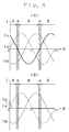
- the conventional motor control apparatus described above monitors which of power supply lines (phase u, phase v, phase w) of AC current is broken or whether or not the current value of each of the current detection values iu, iv, iw becomes zero with the current deviations ⁇ Id, ⁇ Iq on the axis d-q, as shown in Fig. 4(A). For example, because the current detection value iu becomes zero if the power supply line of phase u is broken as shown in Fig. 4(B), the breaking in the power supply line of phase u is detected by the current deviations ⁇ Id, ⁇ Iq obtained by this d/q conversion.
- this current detection value iu deviates to both polarities of positive and negative as sine wave, the current value becomes almost zero when a rotation angle ⁇ , which crosses zero, is located in the interval of ⁇ even if the power supply line is not broken (see Fig. 4).
- the breaking of the power supply line can be detected when the rotation angle ⁇ of the motor is in the interval of ⁇ , the breaking cannot be detected when the rotation angle ⁇ is in the interval of ⁇ . That is, there has been produced such a problem that depending upon a detection timing, absence/presence of a breaking of the power supply line cannot be monitored with the current deviations ⁇ Id, ⁇ Iq on the axis d-q alone.
- an object of the present invention is to provide a method for detecting any breaking of the power supply line of amotor, capable of detecting the breaking of the power supply line of the motor, a motor control apparatus , an electric power steering apparatus and a computer program thereof.
- a breaking detection method for the power supply line of a motor for detecting a breaking of the power supply line for AC current, connected to the motor driven with the AC current produced by converting from two phase to three or higher phase, is characterized in that the breaking of the power supply lines of said motor is detected by detecting a predetermined period in which all following conditions (A) - (C) are satisfied at the same time;
- a breaking of the power supply lines of the motor according to the present invention is detected by detecting a predetermined period in which all following conditions (A) - (C) are satisfied at the same time;
- the technical feature of the breaking detection method of the power supply line of the motor in accordance with the more preferred teaching of the present invention is characterized in that the motor is a brushless DC motor.
- a breaking of the power supply line of the brushless DC motor in accordance with the more preferred teaching of the present invention is detected by detecting a period in which all the conditions (A)-(C) are satisfied.
- (A) the current value of at least one phase of the AC currents supplied to the brushless DC motor is substantially zero ampere
- (B) the angular velocity of the brushless DC motor is over a predetermined value
- (C) the current instruction value to the brushless DC motor is over a predetermined value are the detecting conditions
- erroneous detection upon detecting a power supply line of a single phase can be prevented by the condition (A), erroneous detection when the brushless DC motor is stopped, by the condition (B) and erroneous detection when the current instruction value to the brushless DC motor is smaller (for example, substantially zero), by the condition (C). Therefore, a breaking of the power supply line of the brushless DC motor can be detected securely even when the current detection value of each phase crosses zero.
- a motor control apparatus in accordance with the more preferred teaching of the present invention driven with AC current produced by converting from 2 phase to 3 or higher phase, is characterized in that the breaking of the power supply line of the motor to be controlled is detected according to the breaking detection method for the power supply line of the motor.
- a breaking of the power supply line of the motor to be controlled in accordance with the more preferred teaching of the present invention is detected based on the breaking detection method for the power supply line of the motor.
- the condition (A) the current value of at least one phase of the AC currents supplied to the motor is substantially zero ampere
- the condition (B) the angular velocity of the motor is over a predetermined value
- the condition (C) the current instruction value to the motor is over a predetermined value
- An electric power steering mechanism for assisting steering by detecting a steering condition and driving a motor depending on the steering condition is characterized in that the breaking of the power supply line of the motor to be controlled is detected according to the breaking detection method for the power supply line of the motor.
- a breaking of the power supply line of the motor to assist steering is detected based on the breaking detection method for the power supply line of the motor.
- the condition (A) the current value of at least one phase of the AC currents supplied to the motor is substantially zero ampere
- the condition (B) the angular velocity of the motor is over a predetermined value
- the condition (C) the current instruction value to the motor is over a predetermined value
- erroneous detection upon detecting a power supply line of a single phase can be prevented by the condition (A), erroneous detection when the motor is stopped, by the condition (B) and erroneous detection when the current instruction value to the motor is smaller (for example, substantially zero), by the condition (C). Therefore, a breaking of the power supply line of the motor can be detected securely even when the current detection value of each phase crosses zero.
- a computer program in accordance with the more preferred teaching of the present invention is characterized by including a program for making the breaking detection method for the power supply line of the motor to function by the computer.
- a program for making the breaking detection method for the power supply line of the motor to function by computer is included.
- the breaking detection method for the power supply line of the motor can be made to function by computer according to that program. Therefore, a breaking of the power supply line of the motor can be detected securely by that function of the computer even when the current detection value of each phase crosses zero.
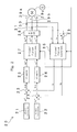
- motor control apparatus The structure of the control apparatus of a motor (hereinafter referred to as motor control apparatus), to which the breaking detection method for the power supply line of a motor of the present invention will be described with reference to Fig. 2.
- Fig. 2 shows main functional blocks, which compose the motor control apparatus 20.
- the motor control apparatus 20 comprises mainly a d-axis instruction 21, a q-axis instruction 22, computing portions 23, 24, PI control portions 25, 26, a 2-phase/3-phase converting portion 27, a pulse width modulating portion 28, current detectors 30, 31, a computing portion 33, a 3-phase/2-phase converting portion 35 and an encoder E. Individual functional portions except the pulse width modulating portion 28 and the encoder E are processed by computation with software through a computer.
- phase u and phase v of the motor M are detected by the current detectors 30, 32, converted to digital current detection values iu, iv and inputted to the 3-phase/2-phase converting portion 35.
- the current iw of phase w can be obtained by subtracting from the current detection values iu, iv and a result obtained by this computation is inputted to the 3-phase/2-phase converting portion 35 as a current value iw of phase w.
- the 3-phase/2-phase converting portion 35 converts the inputted current values iu, iv, iw to current values id, iq through d/q conversion (2-phase conversion) based on a detection signal detected by the encoder E for detecting the rotation angle of the rotator of the motor M and outputs.
- the current values id, iq are respectively inputted to the computing portions 23, 24 as each feed back value.
- the q-axis instruction 22 or the like is inputted to the computing portions 23, 24 as a torque instruction for the motor M. That is, a torque to be generated in the rotator of the motor M is computed based on the q-axis instruction 22 and then inputted to the computing portion 24 as a q-axis current instruction value iq* while exciting current of the rotator of the motor M is computed based on the d-axis instruction 21 and inputted to the computing portion 23 as a d-axis current instruction value id*.
- the d-axis current instruction value id* is set to zero ampere (id* ⁇ 0).
- the d-axis current instruction value id* and a current value id obtained by converting with the 3-phase/2-phase converting portion are inputted to the computing portion 23. Therefore, a deviation between both computed results is outputted in the form of ⁇ id from the computing portion 23 and then inputted to the PI control portion 25.
- the q-axis current instruction value iq* and a current value iq obtained by converting with the 3-phase/2-phase converting portion 35 are inputted to the computing portion 24 and a deviation between both computed results is outputted in the form of ⁇ iq from the computing portion 23 and inputted to the PI control portion 26.
- the PI control portions 25, 26 carry out proportional integration upon the inputted deviations ⁇ id, ⁇ iq and then compute the d-axis voltage instruction value vd* and q-axis voltage instruction value vq* using a predetermined voltage equation so as to output to the 2-phase/3-phase converting portion 27.
- the 2-phase/3-phase converting portion 27 d/q inversion-converts (3-phase conversion) respective inputted d-axis voltage instruction value vd* and q-axis voltage instruction value vq* so as to compute voltage instruction values vu*, vv*, vw*.
- the pulse width modulating portion (PWM) 28 fetches in the voltage instruction values vu*, vv*, vw* and outputs pulse signals having each corresponding pulse width to a driving circuit (not shown).
- the driving circuit applies a driving voltage to the motor M through the power supply lines 29a, 29b, 29c of phase, u, phase v, and phase w.
- the motor control apparatus 20 If the motor control apparatus 20 is constructed as described above, it can be controlled so that the deviation in each of the current instruction value and feedback value is zero. As a result, the motor M can be controlled in terms of its torque and the like.
- breaking detection processing shown in Fig. 1 is formed in a subroutine, it is incorporated in a sequence of timer interruption processing generated every predetermined time.
- a predetermined initialization processing necessary before this breaking detection processing is executed, for example, initialization processing for counter CNT, breaking detection flag and the like, which will be described later, is carried out depending on a main routine calling this breaking detection processing.
- the breaking detection processing three conditions are considered in step S101. More specifically, the first condition of this embodiment is, for example, that the AC current iu (absolute value) supplied to the motor M is substantially 0 ampere or less than 0.5 Aor the iv is substantially 0 or less than 0.5 A or the iw is substantially 0 or less than 0.5 A, the second condition is that the angular velocity of the motor M is 1 rad/s or more and the third condition is that the current instruction value to the motor M is 5 amperes or more.
- a current value iu flowing through the power supply line 29a of phase u shown in Fig. 2 a current iv flowing through the power supply line 29b of phase v and a current iw flowing through the power supply line 29c of phase w are determined based on the outputs of the current detectors 30, 31 and the computation result of the computing portion 33. That is, this is executed by determining whether the current detection values iu, iv, iw inputted to the 3-phase/2-phase converting portion 35 are a predetermined value or less than the predetermined value.
- the first condition whether or not there is any breaking in the power supply lines 29a, 29b, 29c can be determined and by determining which phase a current value satisfying that condition corresponds to, a power supply line having a fear of a breaking can be pinpointed.
- the second condition that "the angular velocity of the motor M is 1 rad/s or more" is determined by subjecting the output of the encoder E for detecting the rotation angle of the motor M to time differentiation so as to obtain an angular velocity. That is, this is executed by determining whether or not the detection signal of the encoder E to be inputted to the 2-phase/3-phase converting portion 27 or the 3-phase/2-phase converting portion 35 is 1 rad/s or more.
- the third condition that "the current instruction value to the motor M is 5 amperes or more" is determined based on the d-axis current instruction value id* by the d-axis instruction 21 and the q-axis current instruction value iq* by the q-axis instruction 22. That is, this is executed by determining whether or not at least any one of the d-axis current instruction value id* or the q-axis instruction value iq* of the motor M is set to 5 amperes or more.
- step S101 If it is determined that all these three conditions are satisfied in step S101 (Yes in step S101), the processing proceeds to step S103, in which 1 is added to the counter CNT1. Namely, the counter CNT, which counts frequencies in which the three conditions are satisfied at the same time, is incremented.
- step S101 if it is determined that these three conditions cannot be satisfied at the same time in step S101 (No in step S101), the processing proceeds to step S105, in which the counter CNT is zero-cleared and then this breaking detection processing is terminated. That is, if the condition of step S101 is not satisfied even once although all the conditions of step S101 are satisfied at the same time, processing of erasing the value on the counter CNT is carried out. Consequently, a further erroneous detection can be prevented.
- step S107 whether or not the value of the counter CNT exceeds 5 is determined. That is, the breaking of the power supply lines 29a, 29b, 29c of the motor M is detected by detecting a predetermined period in which the three conditions are satisfied at the same time in step S101. More specifically, if the frequency in which the condition of step S101 is satisfied exceeds 5 by a result of adding to the counter CNT (Yes in step S107), it is determined that any one of the power supply lines 29a, 29b, 29c is broken and in subsequent step S109, breaking detection flag is turned ON (for example, value 1). Then, this breaking detection processing is terminated.
- this breaking detection processing of this embodiment is timer interruption processing which is activated every predetermined time.
- a predetermined "period in which all the three conditions are satisfied" can be detected by step S107 for determining that the condition of step S101 is satisfied five or more times continuously and step S105 for erasing the value of the counter CNT even if the condition of step S101 is not satisfied even once.
- step S107 because it is not yet determined which of the power supply lines 29a, 29b, 29c is broken if the frequency in which the condition of step S101 is satisfied does not exceed five times (No in step S107), this breaking detection processing is terminated.
- step S101 it is determined (A) that the iu, iv and iw of the AC current (absolute value) supplied to the motor M are less than 0.5 amperes each, (B) that the angular velocity of the motor M is 1 rad/s or more and (C) that at least any one of the current instruction values id*, iq* is 5 amperes or more.
- a predetermined period in which all these three conditions (A)-(C) are satisfied is determined in step S107 so as to determine which of the power supply lines 29a, 29b, 29c is broken and then, the breaking detection flag is set to ON so as to detect any breaking of the line.
- the breaking detection flag as a detection condition that all the three conditions (A)-(C) are satisfied at the same time in a predetermined period is set to ON, an erroneous detection in each of the condition (A) for detecting a breaking of the power supply line of a phase, the condition (B) that the rotation of the motor M is stopped and the condition (C) that the current instruction values id*, iq* to the motor M are less than a predetermined value can be prevented.
- a breaking of the power supply lines 29a, 29b, 29c of the motor M can be detected securely by determining the condition of the breaking detection flag even in a period in which the current detection value of each phase crosses zero.
- step S105 and step S107 Although the above-described breaking detection processing detects a predetermined period in which "all the three conditions are satisfied at the same time" in step S105 and step S107, the present invention is not restricted to this and it is permissible to apply such an algorithm of counting only the frequency that the condition of step S101 is satisfied and setting the breaking detection flag to ON if that value exceeds a predetermined frequency. Consequently, the breaking detection which paid attention to only the frequency that the condition of step S101 is satisfied can be carried out.
- the electric power steering mechanism 50 comprises mainly various kinds of sensors such as a torque sensor 52, a vehicle velocity sensor 54, a revolution number sensor 56, a current sensor 58, an ECU 60, a motor driving circuit 66 and a brushless DC motor BL.
- sensors such as a torque sensor 52, a vehicle velocity sensor 54, a revolution number sensor 56, a current sensor 58, an ECU 60, a motor driving circuit 66 and a brushless DC motor BL.
- the d-axis instruction 21, the q-axis instruction 22, the computing portions 23, 24, the PI control portions 25, 26, the 2-phase/3-phase converting portion 27, the computing portion 33 and the 3-phase/2-phase converting portion 35 are achieved by software which is computed by the CPU 62 in the ECU 60.
- the pulse width modulating portion 28 is achieved by hardware which constructs the ECU 60 or the motor driving circuit 66 and the current detectors 30, 31, the motor M and the encoder E correspond to the current sensor 58, the brushless DC motor BL and the revolution number sensor 56 shown in Fig. 3.
- the torque sensor 52 detects a steering torque from a torsion amount of a torsion bar or the like which connects the input shaft coupled to the vehicle steering wheel with the output shaft coupled to the steering mechanism such that they can be rotated relatively.
- This detected steering torque is inputted to the ECU 60 together with the vehicle velocity detected by the vehicle velocity sensor 54.
- the revolution number of the brushless DC motor BL assisting the steering force of a steering wheel is detected by the revolution number sensor 56 and further, the current values iu, iv flowing through the phase u and phase v of the brushless DC motor BL are detected by the current sensor 58 and inputted to the ECU 60.
- the CPU 62 which constructs the ECU 60, determines the current instruction values id*, iq* to be transmitted to the motor driving circuit 66 based on a steering torque, a vehicle velocity and a motor revolution number inputted through an interface 64. That is, these information pieces are inputted to the d-axis instruction 21 and the q-axis instruction 22 shown in Fig. 2 and converted to the d-axis current instruction value id* and q-axis current instruction value iq* so as to determine the current instruction values id*, iq*.
- the PI control portions 25, 26 proportional-integrate the deviations ⁇ id, ⁇ iq relative to the feedback values id, iq inputted to the computing portions 23, 24 so as to output the d-axis voltage instruction values vd* and the q-axis voltage instruction value vq* and then these values are d/q inversion converted by the 2-phase/3-phase converting portion 27 so as to compute the voltage instruction values vu*, vv*, vw*. Then, these voltage instruction values vu*, vv*, vw* are outputted to the pulse width modulating portion 28 of the motor driving circuit 66.
- the voltage instruction values vu*, vv*, vw* transmitted from the CPU 62 are outputted to the brushless DC motor BL through the power supply lines 29a, 29b, 29c and currents of phase u and phase v flowing through the power supply lines 29a, 29b, 29c are detected by the current sensor 58 and the current detection values iu, iv are inputted to the ECU 60. Therefore, the brushless DC motor BL can generate an assist torque for assisting the steering force or generate a torque for restoring the steering wheel.
- the CPU 62 of the ECU 60 executes the breaking detection processing shown in Fig. 1 in the sequential timer interruption processing which is generated every predetermined time so as to detect a breaking of the power supply lines 29a, 29b, 29c of the brushless DC motor BL assisting the steering action.
- step S107 it is determined (A) that the iu, iv, and iw of the DC current (absolute value) supplied to the brushless DC motor BL are less than 0.5 amperes respectively, (B) that the angular velocity of the brushless DC motor BL or the steering velocity of the steering wheel is 1 rad/s or more and (C) that at least any one of the current instruction values id*, iq* relative to the brushless DC motor is 5 amperes or more, and a predetermined period in which all these three conditions (A)-(C) are satisfied at the same time is determined in step S107 so as to determine that any one of the power supply lines 29a, 29b, 29c of the brushless DC motor BL is broken. Then, the breaking detection flag is set to ON so as to detect any breaking of the line.
- the breaking detection flag as a detection condition that all the three conditions (A)-(C) are satisfied at the same time in a predetermined period is set to ON, an erroneous detection in each of the condition (A) for detecting a breaking of the power supply line of a phase, the condition (B) that the rotation of the brushless DC motor BL is stopped and the condition (C) that the current instruction values id*, iq* to the brushless DC motor BL are less than a predetermined value can be prevented.
- a breaking of the power supply lines 29a, 29b, 29c in the brushless DC motor BL can be detected securely by determining the condition of the breaking detection flag even in a period in which the current detection value of each phase crosses zero.
- the computer program including such a breaking detection processing can detect any breaking of the power supply lines for AC current supplied to the motor in such an operating environment comprising "current detecting means for detecting an AC current supplied to the motor", “angular velocity detecting means for detecting the angular velocity of the motor” and “current instruction value detecting means for detecting the current instruction value for the motor”.
- breaking detection processing it is determined that (A) iu of AC current (absolute value) supplied to a motor is less than 0.5 amperes or iv thereof is less 0.5 amperes or iw thereof is less than 0.5 amperes, (B) the angular velocity of the motor is 1 rad/s or more and (C) at least any one of the current instruction values id*, iq* is 5 amperes or more in a step and then, a period in which all these three conditions (A)-(C) are satisfied at the same time is determined in another step. Consequently, it is determined that any one of the power supply lines in the motor is broken and a breaking detection flag is set to ON so as to detect the breaking.
Landscapes
- Engineering & Computer Science (AREA)
- Chemical & Material Sciences (AREA)
- Combustion & Propulsion (AREA)
- Transportation (AREA)
- Mechanical Engineering (AREA)
- Control Of Ac Motors In General (AREA)
- Control Of Motors That Do Not Use Commutators (AREA)
- Steering Control In Accordance With Driving Conditions (AREA)
- Control Of Electric Motors In General (AREA)
- Power Steering Mechanism (AREA)
Applications Claiming Priority (2)
| Application Number | Priority Date | Filing Date | Title |
|---|---|---|---|
| JP2001262985A JP3801471B2 (ja) | 2001-08-31 | 2001-08-31 | ブラシレスdcモータの電力供給線の断線検出方法、それを用いたブラシレスdcモータの制御装置、電気式動力舵取装置およびコンピュータプログラム |
| JP2001262985 | 2001-08-31 |
Publications (2)
| Publication Number | Publication Date |
|---|---|
| EP1292012A2 true EP1292012A2 (de) | 2003-03-12 |
| EP1292012A3 EP1292012A3 (de) | 2004-04-28 |
Family
ID=19089809
Family Applications (1)
| Application Number | Title | Priority Date | Filing Date |
|---|---|---|---|
| EP02019376A Withdrawn EP1292012A3 (de) | 2001-08-31 | 2002-08-29 | Bruchdetektion einer Motorstromversorgungsleitung, Vorrichtung zur Motorsteuerung und elektrische Servolenkung mit demselben und Computerprogramm dafür |
Country Status (3)
| Country | Link |
|---|---|
| US (1) | US7215518B2 (de) |
| EP (1) | EP1292012A3 (de) |
| JP (1) | JP3801471B2 (de) |
Cited By (6)
| Publication number | Priority date | Publication date | Assignee | Title |
|---|---|---|---|---|
| WO2004093302A3 (ja) * | 2003-04-18 | 2005-01-20 | Yaskawa Denki Seisakusho Kk | Acサーボドライバのモータ動力線断線検出方法 |
| CN102411111A (zh) * | 2010-09-17 | 2012-04-11 | 现代自动车株式会社 | 电动机的电力电缆断路的检测方法 |
| CN103543373A (zh) * | 2012-07-13 | 2014-01-29 | Ls产电株式会社 | 在逆变器系统中检测电力电缆的断开状态的方法 |
| CN105099325A (zh) * | 2014-05-08 | 2015-11-25 | 发那科株式会社 | 电动机控制装置 |
| CN102411111B (zh) * | 2010-09-17 | 2016-12-14 | 现代自动车株式会社 | 电动机的电力电缆断路的检测方法 |
| WO2020133876A1 (zh) * | 2018-12-26 | 2020-07-02 | 南京埃斯顿自动化股份有限公司 | 一种伺服系统动力电缆断线检测的方法 |
Families Citing this family (11)
| Publication number | Priority date | Publication date | Assignee | Title |
|---|---|---|---|---|
| US8055410B2 (en) * | 2005-05-30 | 2011-11-08 | Jtekt Corporation | Electric power steering system |
| JP4876838B2 (ja) * | 2006-10-12 | 2012-02-15 | 株式会社ジェイテクト | モータ制御装置 |
| JP4696146B2 (ja) | 2008-06-27 | 2011-06-08 | 株式会社日立製作所 | 断線検出方法および電力変換装置 |
| JP5171487B2 (ja) * | 2008-09-02 | 2013-03-27 | 本田技研工業株式会社 | ステアリング装置 |
| JP5942337B2 (ja) | 2011-04-28 | 2016-06-29 | 株式会社ジェイテクト | 車両用操舵装置 |
| JP5810905B2 (ja) * | 2011-12-28 | 2015-11-11 | 株式会社デンソー | モータ制御装置 |
| JP5527629B2 (ja) * | 2012-04-22 | 2014-06-18 | 株式会社デンソー | 交流電動機の制御装置 |
| JP5910460B2 (ja) | 2012-10-26 | 2016-04-27 | 株式会社デンソー | 断線検出装置 |
| KR101452636B1 (ko) * | 2013-06-03 | 2014-10-22 | 엘에스산전 주식회사 | 인버터 시스템 및 이의 전력 케이블 상태 검출 방법 |
| CN104242767A (zh) * | 2014-09-10 | 2014-12-24 | 深圳市微秒控制技术有限公司 | 伺服电机动力线断线检测方法 |
| DE102023200597A1 (de) | 2023-01-25 | 2024-07-25 | Lenze Swiss Ag | Verfahren zum Betreiben eines Frequenzumrichters und Frequenzumrichter |
Family Cites Families (11)
| Publication number | Priority date | Publication date | Assignee | Title |
|---|---|---|---|---|
| JPS58205211A (ja) * | 1982-05-26 | 1983-11-30 | Fanuc Ltd | 障害自己診断機能付パルスエンコ−ダ |
| US4834201A (en) * | 1987-03-19 | 1989-05-30 | Nippon Seiko Kabushiki Kaisha | Electrical power steering apparatus |
| US5306889A (en) * | 1991-07-05 | 1994-04-26 | Sodick Co., Ltd. | Wire cut electrical discharge machining apparatus |
| JP2752539B2 (ja) * | 1991-09-21 | 1998-05-18 | 株式会社日立製作所 | 車両用電動機の制御装置 |
| US5650708A (en) * | 1992-12-08 | 1997-07-22 | Nippondenso Co., Ltd. | Inverter control apparatus using a two-phase modulation method |
| JP2932335B2 (ja) * | 1993-07-30 | 1999-08-09 | 光洋精工株式会社 | 電動パワーステアリング装置 |
| DE69401256T2 (de) * | 1993-09-17 | 1997-05-28 | Fuji Electric Co Ltd | Steuergerät bzw. Steuerverfahren und Gerät und Verfahren zur Feststellung eines Fehlfunktionierens eines Wechselstrommotors |
| US5572142A (en) * | 1994-05-06 | 1996-11-05 | Nissan Motor Co., Ltd. | Apparatus and method for diagnosing presence or absence of breakage in electromagnetic coil means applicable to breakage diagnosis for stepping motor |
| JPH0861287A (ja) | 1994-08-11 | 1996-03-08 | Ebara Corp | ポンプ用インバータユニット及びそのユニットを備えたポンプ装置 |
| JP2000177477A (ja) * | 1998-12-14 | 2000-06-27 | Ichikoh Ind Ltd | 車両用前照灯光軸調整装置 |
| JP3923455B2 (ja) * | 2003-08-22 | 2007-05-30 | 本田技研工業株式会社 | 電動パワーステアリング装置 |
-
2001
- 2001-08-31 JP JP2001262985A patent/JP3801471B2/ja not_active Expired - Fee Related
-
2002
- 2002-08-29 EP EP02019376A patent/EP1292012A3/de not_active Withdrawn
- 2002-08-29 US US10/230,225 patent/US7215518B2/en not_active Expired - Fee Related
Cited By (9)
| Publication number | Priority date | Publication date | Assignee | Title |
|---|---|---|---|---|
| WO2004093302A3 (ja) * | 2003-04-18 | 2005-01-20 | Yaskawa Denki Seisakusho Kk | Acサーボドライバのモータ動力線断線検出方法 |
| US7301737B2 (en) | 2003-04-18 | 2007-11-27 | Kabushiki Kaisha Yaskawa Denki | Motor power line break detection method in AC servo driver |
| CN102411111A (zh) * | 2010-09-17 | 2012-04-11 | 现代自动车株式会社 | 电动机的电力电缆断路的检测方法 |
| CN102411111B (zh) * | 2010-09-17 | 2016-12-14 | 现代自动车株式会社 | 电动机的电力电缆断路的检测方法 |
| CN103543373A (zh) * | 2012-07-13 | 2014-01-29 | Ls产电株式会社 | 在逆变器系统中检测电力电缆的断开状态的方法 |
| CN105099325A (zh) * | 2014-05-08 | 2015-11-25 | 发那科株式会社 | 电动机控制装置 |
| US9964582B2 (en) | 2014-05-08 | 2018-05-08 | Fanuc Corporation | Motor control device that detects breakage of motor power line or power element abnormality of motor power conversion device |
| DE102015005513B4 (de) | 2014-05-08 | 2018-05-24 | Fanuc Corporation | Motorsteuerung mit Detektion von Defekten in der Motorstromversorgungsleitung oder in einem Leistungselement der Motorstromversorgungskonversionseinrichtung |
| WO2020133876A1 (zh) * | 2018-12-26 | 2020-07-02 | 南京埃斯顿自动化股份有限公司 | 一种伺服系统动力电缆断线检测的方法 |
Also Published As
| Publication number | Publication date |
|---|---|
| EP1292012A3 (de) | 2004-04-28 |
| JP2003079173A (ja) | 2003-03-14 |
| US7215518B2 (en) | 2007-05-08 |
| JP3801471B2 (ja) | 2006-07-26 |
| US20030058589A1 (en) | 2003-03-27 |
Similar Documents
| Publication | Publication Date | Title |
|---|---|---|
| US7215518B2 (en) | Motor power supply line breaking detection method, motor control apparatus and electric power steering mechanism using the same and computer program thereof | |
| US7188702B2 (en) | Electric power steering apparatus | |
| US6906492B2 (en) | Motor abnormality detection apparatus and electric power steering control system | |
| JP5012258B2 (ja) | 電動パワーステアリング装置 | |
| EP1093992B1 (de) | Elektrische Servolenkung für ein Fahrzeug | |
| EP2423074B1 (de) | Fahrzeuglenkungssystem | |
| EP1873900B1 (de) | Steuerung und Steuerungsverfahren für einen Permanentmagnetdrehmotor | |
| US8983727B2 (en) | Steering control apparatus | |
| US7813626B2 (en) | Motor controller and electric power steering apparatus | |
| US6427105B1 (en) | Electric power steering control system and control method thereof | |
| JP2001018822A (ja) | 車両の電動パワーステアリング装置 | |
| US11312409B2 (en) | Steering control device | |
| JP3567770B2 (ja) | モータ制御装置 | |
| JP2002345285A (ja) | 回転角センサの監視システム | |
| US7336456B2 (en) | Control-motor system | |
| EP1557940B1 (de) | Motorregler | |
| US6796400B2 (en) | Electric power steering mechanism control method and electric power steering mechanism | |
| JP3624737B2 (ja) | モータ制御装置 | |
| JP2003319684A (ja) | 電動パワーステアリング装置のモータ制御装置 | |
| JP2005088709A (ja) | ステアリング装置 | |
| JP2003289688A (ja) | 電動パワーステアリング装置 |
Legal Events
| Date | Code | Title | Description |
|---|---|---|---|
| PUAI | Public reference made under article 153(3) epc to a published international application that has entered the european phase |
Free format text: ORIGINAL CODE: 0009012 |
|
| AK | Designated contracting states |
Kind code of ref document: A2 Designated state(s): AT BE BG CH CY CZ DE DK EE ES FI FR GB GR IE IT LI LU MC NL PT SE SK TR Designated state(s): AT BE BG CH CY CZ DE DK EE ES FI FR GB GR IE IT LI LU MC NL PT SE SK TR |
|
| AX | Request for extension of the european patent |
Extension state: AL LT LV MK RO SI |
|
| PUAL | Search report despatched |
Free format text: ORIGINAL CODE: 0009013 |
|
| AK | Designated contracting states |
Kind code of ref document: A3 Designated state(s): AT BE BG CH CY CZ DE DK EE ES FI FR GB GR IE IT LI LU MC NL PT SE SK TR |
|
| AX | Request for extension of the european patent |
Extension state: AL LT LV MK RO SI |
|
| RIC1 | Information provided on ipc code assigned before grant |
Ipc: 7B 62D 5/04 B Ipc: 7H 02H 7/08 B Ipc: 7H 02P 7/00 B Ipc: 7H 02P 21/00 A |
|
| 17P | Request for examination filed |
Effective date: 20040816 |
|
| AKX | Designation fees paid |
Designated state(s): DE FR GB |
|
| RAP1 | Party data changed (applicant data changed or rights of an application transferred) |
Owner name: JTEKT CORPORATION |
|
| RIN1 | Information on inventor provided before grant (corrected) |
Inventor name: SUZUKI, TAKAYOSHI Inventor name: SAKAI, ATSUO Inventor name: MATSUMOTO, TSUTOMU |
|
| STAA | Information on the status of an ep patent application or granted ep patent |
Free format text: STATUS: THE APPLICATION IS DEEMED TO BE WITHDRAWN |
|
| 18D | Application deemed to be withdrawn |
Effective date: 20100302 |