EP1291261A2 - Engrenage de direction - Google Patents
Engrenage de direction Download PDFInfo
- Publication number
- EP1291261A2 EP1291261A2 EP02019834A EP02019834A EP1291261A2 EP 1291261 A2 EP1291261 A2 EP 1291261A2 EP 02019834 A EP02019834 A EP 02019834A EP 02019834 A EP02019834 A EP 02019834A EP 1291261 A2 EP1291261 A2 EP 1291261A2
- Authority
- EP
- European Patent Office
- Prior art keywords
- steering gear
- compensating member
- gear according
- pressure piece
- spring
- Prior art date
- Legal status (The legal status is an assumption and is not a legal conclusion. Google has not performed a legal analysis and makes no representation as to the accuracy of the status listed.)
- Withdrawn
Links
Images

Classifications
-
- B—PERFORMING OPERATIONS; TRANSPORTING
- B62—LAND VEHICLES FOR TRAVELLING OTHERWISE THAN ON RAILS
- B62D—MOTOR VEHICLES; TRAILERS
- B62D3/00—Steering gears
- B62D3/02—Steering gears mechanical
- B62D3/12—Steering gears mechanical of rack-and-pinion type
- B62D3/123—Steering gears mechanical of rack-and-pinion type characterised by pressure yokes
-
- F—MECHANICAL ENGINEERING; LIGHTING; HEATING; WEAPONS; BLASTING
- F16—ENGINEERING ELEMENTS AND UNITS; GENERAL MEASURES FOR PRODUCING AND MAINTAINING EFFECTIVE FUNCTIONING OF MACHINES OR INSTALLATIONS; THERMAL INSULATION IN GENERAL
- F16H—GEARING
- F16H55/00—Elements with teeth or friction surfaces for conveying motion; Worms, pulleys or sheaves for gearing mechanisms
- F16H55/02—Toothed members; Worms
- F16H55/26—Racks
- F16H55/28—Special devices for taking up backlash
- F16H55/283—Special devices for taking up backlash using pressure yokes
- F16H55/286—Special devices for taking up backlash using pressure yokes with asymmetric layout of the yoke
-
- Y—GENERAL TAGGING OF NEW TECHNOLOGICAL DEVELOPMENTS; GENERAL TAGGING OF CROSS-SECTIONAL TECHNOLOGIES SPANNING OVER SEVERAL SECTIONS OF THE IPC; TECHNICAL SUBJECTS COVERED BY FORMER USPC CROSS-REFERENCE ART COLLECTIONS [XRACs] AND DIGESTS
- Y10—TECHNICAL SUBJECTS COVERED BY FORMER USPC
- Y10T—TECHNICAL SUBJECTS COVERED BY FORMER US CLASSIFICATION
- Y10T74/00—Machine element or mechanism
- Y10T74/19—Gearing
- Y10T74/19623—Backlash take-up
-
- Y—GENERAL TAGGING OF NEW TECHNOLOGICAL DEVELOPMENTS; GENERAL TAGGING OF CROSS-SECTIONAL TECHNOLOGIES SPANNING OVER SEVERAL SECTIONS OF THE IPC; TECHNICAL SUBJECTS COVERED BY FORMER USPC CROSS-REFERENCE ART COLLECTIONS [XRACs] AND DIGESTS
- Y10—TECHNICAL SUBJECTS COVERED BY FORMER USPC
- Y10T—TECHNICAL SUBJECTS COVERED BY FORMER US CLASSIFICATION
- Y10T74/00—Machine element or mechanism
- Y10T74/19—Gearing
- Y10T74/19642—Directly cooperating gears
- Y10T74/1967—Rack and pinion
Definitions
- the invention relates to a steering gear with a housing, one in which Housing displaceable rack, a drive pinion and a pressure piece, that presses the rack against the drive pinion.
- Generic steering gears are used by the vehicle driver Movements of the steering wheel in a change in the position of wheels in usually sit on one axis.
- the rotational movement of the steering wheel is converted into a rotational movement of a implemented a housing of the steering gear drive pinion.
- the Drive pinion acts on a sliding rack of the steering gear, this again via a linkage on the wheels to be steered.
- the one in the housing located, displaceable rack is acted upon by a pressure piece, that it is pressed against a drive pinion.
- the pressure that that Exerts pressure piece on the rack is dimensioned so that an optimal There is a connection between the rack and the drive pinion and thus a smooth, responsive steering can be realized.
- the object of the invention is to generic steering gear in this way improve that in all operating conditions smooth and good Power transmission can be achieved and the maintenance effort even after a long time Operating time is minimized.
- the invention are in the steering gear of the type mentioned Compensating member, which is supported with a curved surface on the pressure piece, and a torsion spring is provided which the compensating member with a torque in such a direction that the pressure piece from the compensating member is pushed towards the drive pinion.
- This ensures that Compensating link the rack over the pressure piece in self-adjusting Way with increasing wear of the transmission against the drive pinion suppressed.
- This construction of the gearbox simplifies assembly on the one hand Band because certain individual adjustment steps no longer have to be carried out.
- tolerances of components can be compensated for these can be manufactured with less manufacturing accuracy. Especially It is advantageous that even during operation of the vehicle when the Steering gear no more service or repair work to be carried out have to.
- the curve surface of the compensating element slope curve surfaces in the manner of Has screw surfaces and that two of the slope curve surfaces over extend an angle of 180 °. It will be a particularly beneficial one Execution created, which a symmetrical introduction of the forces from Compensating piece on the pressure piece allows.
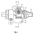
- FIG. 1 is a plan view of the steering gear according to the invention.
- a rack 12 which is displaceable in the housing is connected to a wheel axle (not shown), a drive pinion 14, which via a (not shown) steering shaft with a (not shown) Steering wheel communicates, and a thrust piece 16 which against the rack the drive pinion presses.
- a compensating member 18 is supported on the pressure piece 16 from.
- a torsion spring 20 designed as a leg spring lies with a first one Leg 20a on a radially extending shoulder 18a of the compensating member 18, whereby the position of the first spring leg 20a is particularly secure is set.
- a second leg 20b of the torsion spring 20 is supported on one Support disc 22 from.
- the support disc is provided with a disc groove 22a, in which the second leg 20b is received, whereby a secure Fixation of the torsion spring 20 is reached.
- the leg spring has several Turns 20c.
- Between the flat underside of the compensating member 18 and the Support disc 22 is a corrugated disc 24 which is resilient (Travel a). This can result in production-related deviations in the Gear teeth of drive pinion 14 and rack 12 balanced and so on Jamming during a longitudinal movement of the rack can be avoided.
- On typical value for the spring travel a is 0.1 to 0.2 mm.
- the torsion spring 20 acts on the compensating member 18 via the first Leg 20a force on the paragraph 18a with a torque that the compensating member is pressed against the pressure piece.
- the turns 20c allow the torsion spring 20 to act as a compression spring in a second function. This is Particularly advantageous since the torsion spring 20 also axially counteracts the pressure piece 16 the drive pinion presses.
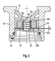
- FIG 3 is a detailed view of a preferred embodiment of the Compensation piece 18 shown in an annular design.
- Slope curve surfaces 18b, 18c of the compensating member 18 are in the manner of screw surfaces executed and extend over an angle of 180 °.
- the paragraphs 18a, 18d separate the gradient curve surface 18b from the gradient curve surface 18c.
- the torsion spring is in the Arranged inside (see Figure 2), which is a particularly compact and space-saving Construction allowed.
- the slope angle of the slope curve surfaces 18b, 18c is very small at 6 °. The frictional forces between the compensating member 18 and the pressure piece 16 are so large that the force applied by the rack Pressure piece can no longer evade according to Figure 2 below.
- the Diameter of the compensating member 18 is chosen with about 20 mm so that the Stroke of the gradient curve surfaces 18b, 18c over an angular range ⁇ about 3 mm is, the angular range ⁇ the adjustment range for the compensating piece 18 forms.
- a second angular range ⁇ 180 ° - ⁇ defines the minimum contact area between the slope curve surface 18b and 18c on the one hand and the latter opposite surface of the pressure piece 16 on the other hand, which is required to ensure a safe and pressure-minimized contact between pressure piece 16 and to achieve compensating member 18.
Landscapes
- Engineering & Computer Science (AREA)
- Mechanical Engineering (AREA)
- General Engineering & Computer Science (AREA)
- Chemical & Material Sciences (AREA)
- Combustion & Propulsion (AREA)
- Transportation (AREA)
- Transmission Devices (AREA)
- Springs (AREA)
- Power Steering Mechanism (AREA)
- Gears, Cams (AREA)
Applications Claiming Priority (2)
| Application Number | Priority Date | Filing Date | Title |
|---|---|---|---|
| DE20114759U | 2001-09-06 | ||
| DE20114759U DE20114759U1 (de) | 2001-09-06 | 2001-09-06 | Lenkgetriebe |
Publications (2)
| Publication Number | Publication Date |
|---|---|
| EP1291261A2 true EP1291261A2 (fr) | 2003-03-12 |
| EP1291261A3 EP1291261A3 (fr) | 2006-04-19 |
Family
ID=7961417
Family Applications (1)
| Application Number | Title | Priority Date | Filing Date |
|---|---|---|---|
| EP02019834A Withdrawn EP1291261A3 (fr) | 2001-09-06 | 2002-09-06 | Engrenage de direction |
Country Status (3)
| Country | Link |
|---|---|
| US (1) | US20030074996A1 (fr) |
| EP (1) | EP1291261A3 (fr) |
| DE (1) | DE20114759U1 (fr) |
Cited By (3)
| Publication number | Priority date | Publication date | Assignee | Title |
|---|---|---|---|---|
| DE102006016110A1 (de) * | 2006-04-04 | 2007-10-18 | Thyssenkrupp Presta Steertec Gmbh | Zahnstangenlenkgetriebe mit automatischer Nachstellung des Druckstücks |
| CN101285521B (zh) * | 2007-04-10 | 2011-02-09 | 万都株式会社 | 用于转向装置的支撑轭的自动间距补偿器 |
| WO2012076169A2 (fr) | 2010-12-08 | 2012-06-14 | Thyssenkrupp Presta Ag | Direction à crémaillère avec étanchéité simple |
Families Citing this family (20)
| Publication number | Priority date | Publication date | Assignee | Title |
|---|---|---|---|---|
| DE10344726B4 (de) * | 2003-09-26 | 2016-03-10 | Audi Ag | Zahnstangenlenkung für ein Kraftfahrzeug |
| US8555741B2 (en) * | 2005-06-30 | 2013-10-15 | Steering Solutions Ip Holding Corporation | Power steering apparatus with adjustment device |
| US8336413B2 (en) * | 2005-06-30 | 2012-12-25 | Steering Solutions Ip Holding Corporation | Rack and pinion steering apparatus having rack bearing wear compensation with damping |
| US7980152B2 (en) * | 2005-06-30 | 2011-07-19 | Nexteer (Beijing) Technology Co., Ltd. | Rack and pinion steering gear assembly having self-adjusting eccentric rack bearing |
| DE102006023795A1 (de) * | 2006-03-04 | 2007-09-06 | Schaeffler Kg | Druckstückeinheit für ein Zahnstangenlenkgetriebe |
| KR20070092018A (ko) * | 2006-03-08 | 2007-09-12 | 주식회사 만도 | 랙 피니언 방식 조향장치의 서포트 요크 자동 유격보상장치 |
| KR101163260B1 (ko) * | 2007-05-31 | 2012-07-05 | 주식회사 만도 | 서포트 요크 클리어런스 자동 조정장치 |
| US7487984B1 (en) * | 2007-10-01 | 2009-02-10 | Gm Global Technology Operations, Inc. | Steering rack wear compensator |
| US7930951B2 (en) * | 2008-03-07 | 2011-04-26 | Nexteer (Beijing) Technology Co., Ltd. | Rack and pinion steering gear with self-adjusting rack bearing |
| DE102008054782B4 (de) | 2008-12-17 | 2012-10-25 | Zf Lenksysteme Gmbh | Vorrichtung zum Andrücken einer Zahnstange |
| DE102009028380B4 (de) * | 2009-08-10 | 2015-05-07 | Zf Lenksysteme Gmbh | Vorrichtung zum Andrücken einer Schnecke |
| DE102009046304B4 (de) * | 2009-11-03 | 2020-03-05 | Robert Bosch Automotive Steering Gmbh | Nachstelleinrichtung |
| KR101393123B1 (ko) * | 2010-02-09 | 2014-05-08 | 주식회사 만도 | 자동차 조향장치의 랙바 지지장치 |
| DE112011101464A5 (de) | 2010-04-28 | 2013-03-07 | Zf Lenksysteme Gmbh | Vorrichtung zum andrücken einer zahnstange |
| DE102010029603A1 (de) * | 2010-06-02 | 2011-12-08 | Zf Lenksysteme Gmbh | Vorrichtung zum Andrücken einer Zahnstange |
| JP5928217B2 (ja) * | 2012-07-20 | 2016-06-01 | 株式会社ジェイテクト | ラックシャフト支持装置、およびこの装置を備えるステアリング装置 |
| KR102096989B1 (ko) * | 2013-11-04 | 2020-04-03 | 현대모비스 주식회사 | 차량의 요크유격보상장치 |
| CN109960157A (zh) * | 2017-12-22 | 2019-07-02 | 深圳市优必选科技有限公司 | 舵机运动的平滑处理方法、装置、终端设备和存储介质 |
| DE102019118673A1 (de) | 2019-07-10 | 2021-01-14 | Thyssenkrupp Ag | Elektromechanische Servolenkung mit Schwenkpendel-Lageranordnung |
| DE102021208031A1 (de) * | 2021-07-26 | 2023-01-26 | Zf Automotive Germany Gmbh | Vorrichtung zum Andrücken einer Zahnstange an ein Ritzel sowie Lenkung für ein Kraftfahrzeug mit einer solchen Vorrichtung |
Citations (6)
| Publication number | Priority date | Publication date | Assignee | Title |
|---|---|---|---|---|
| GB1181738A (en) * | 1967-09-07 | 1970-02-18 | Cam Gears Ltd | Improvements in or relating to Rack and Pinion Assemblies |
| US4095482A (en) * | 1976-02-18 | 1978-06-20 | Volkswagenwerk Aktiengesellschaft | Rack and pinion steering apparatus |
| GB2037931A (en) * | 1978-11-23 | 1980-07-16 | Cam Gears Ltd | Rack-and-pinion Gearing |
| EP0461945A1 (fr) * | 1990-06-15 | 1991-12-18 | Regie Nationale Des Usines Renault S.A. | Carter pour mécanisme de direction à pignon et crémaillère |
| JPH04368283A (ja) * | 1991-06-17 | 1992-12-21 | Jidosha Kiki Co Ltd | ラックピニオン型舵取り装置 |
| US6019012A (en) * | 1998-09-24 | 2000-02-01 | Trw Inc. | Lash adjustment mechanism |
-
2001
- 2001-09-06 DE DE20114759U patent/DE20114759U1/de not_active Expired - Lifetime
-
2002
- 2002-09-05 US US10/236,073 patent/US20030074996A1/en not_active Abandoned
- 2002-09-06 EP EP02019834A patent/EP1291261A3/fr not_active Withdrawn
Patent Citations (6)
| Publication number | Priority date | Publication date | Assignee | Title |
|---|---|---|---|---|
| GB1181738A (en) * | 1967-09-07 | 1970-02-18 | Cam Gears Ltd | Improvements in or relating to Rack and Pinion Assemblies |
| US4095482A (en) * | 1976-02-18 | 1978-06-20 | Volkswagenwerk Aktiengesellschaft | Rack and pinion steering apparatus |
| GB2037931A (en) * | 1978-11-23 | 1980-07-16 | Cam Gears Ltd | Rack-and-pinion Gearing |
| EP0461945A1 (fr) * | 1990-06-15 | 1991-12-18 | Regie Nationale Des Usines Renault S.A. | Carter pour mécanisme de direction à pignon et crémaillère |
| JPH04368283A (ja) * | 1991-06-17 | 1992-12-21 | Jidosha Kiki Co Ltd | ラックピニオン型舵取り装置 |
| US6019012A (en) * | 1998-09-24 | 2000-02-01 | Trw Inc. | Lash adjustment mechanism |
Non-Patent Citations (1)
| Title |
|---|
| PATENT ABSTRACTS OF JAPAN Bd. 017, Nr. 248 (M-1411), 18. Mai 1993 (1993-05-18) -& JP 04 368283 A (JIDOSHA KIKI CO LTD), 21. Dezember 1992 (1992-12-21) * |
Cited By (6)
| Publication number | Priority date | Publication date | Assignee | Title |
|---|---|---|---|---|
| DE102006016110A1 (de) * | 2006-04-04 | 2007-10-18 | Thyssenkrupp Presta Steertec Gmbh | Zahnstangenlenkgetriebe mit automatischer Nachstellung des Druckstücks |
| US7954396B2 (en) | 2006-04-04 | 2011-06-07 | Thyssenkrupp Presta Steertec Gmbh | Rack and pinion steering gear with automatic adjustment of the thrust element |
| CN101285521B (zh) * | 2007-04-10 | 2011-02-09 | 万都株式会社 | 用于转向装置的支撑轭的自动间距补偿器 |
| WO2012076169A2 (fr) | 2010-12-08 | 2012-06-14 | Thyssenkrupp Presta Ag | Direction à crémaillère avec étanchéité simple |
| DE102010053770A1 (de) | 2010-12-08 | 2012-06-14 | Thyssenkrupp Presta Ag | Zahnstangenlenkung mit einfacher Abdichtung |
| DE102010053770B4 (de) * | 2010-12-08 | 2020-11-12 | Thyssenkrupp Presta Aktiengesellschaft | Zahnstangenlenkung mit einfacher Abdichtung |
Also Published As
| Publication number | Publication date |
|---|---|
| DE20114759U1 (de) | 2002-01-17 |
| US20030074996A1 (en) | 2003-04-24 |
| EP1291261A3 (fr) | 2006-04-19 |
Similar Documents
| Publication | Publication Date | Title |
|---|---|---|
| EP1291261A2 (fr) | Engrenage de direction | |
| EP1807639B1 (fr) | Dispositif pour comprimer une cremaillere | |
| EP1984656B1 (fr) | Dispositif de changement de vitesse pour une boite de vitesses de vehicule automobile | |
| DE102010002285A1 (de) | Schraubradgetriebe für eine Lenkung eines Kraftfahrzeugs | |
| EP1992842A2 (fr) | Engrenage pour un dispositif de réglage, en particulier un dispositif de réglage de véhicule automobile doté d'un équilibrage de jeu | |
| WO2015169844A1 (fr) | Réducteur et système de direction | |
| DE3230664C2 (fr) | ||
| WO2010069942A1 (fr) | Dispositif d'application d'une crémaillère | |
| DE102016007542A1 (de) | Kugelgewindetrieb einer elektromechanischen Servolenkung mit Umlenkkörper für eine Kugelrückführung | |
| WO2012152487A1 (fr) | Élément de pression d'une direction à crémaillère | |
| EP3837454A1 (fr) | Arrangement de roues dentées et actionneur | |
| WO1990003908A2 (fr) | Direction assistee hydraulique pour vehicules automobiles | |
| DE2641698B2 (de) | Umlaufrädergetriebe mit stufenlos willkürlich einstellbarer Übersetzung und mit drehmomentabhängiger Überlagerung der Übersetzungseinstellung | |
| WO2017140444A1 (fr) | Articulation à rotule | |
| DE102005021460A1 (de) | Verstelleinrichtung für Kupplungen und Getriebebremsen, insbesondere von Kraftfahrzeugen zum Verstellen eines einen Auflage- und Drehpunkt eines gebogenen Hebels bildenden Auflagerelements | |
| WO2004005761A1 (fr) | Dispositif de pression | |
| DE102012103857A1 (de) | Vorrichtung zum Andrücken einer Schnecke oder eines Schraubritzels an ein Schneckenrad oder an ein Schraubrad | |
| DE2735958A1 (de) | Lenkgetriebe fuer kraftfahrzeuge | |
| DE102011006965A1 (de) | Vorrichtung zum Verändern eines Betriebszustandes eines Schaltelementes mit zwei Schaltelementen | |
| DE602004005063T2 (de) | Doppelkupplung, insbesondere für ein kraftfahrzeug | |
| DE3029935C2 (de) | Ventil | |
| DE10107740A1 (de) | Zahnstangenlenkung mit deformierbarem Druckstück für Kraftfahrzeuge | |
| DE3109622A1 (de) | Servolenkvorrichtung fuer kraftfahrzeuge | |
| EP3774497B1 (fr) | Dispositif de direction pourvu d'un couple de résistance de direction simulé | |
| WO2012065722A1 (fr) | Guide de crémaillère monté sur galets |
Legal Events
| Date | Code | Title | Description |
|---|---|---|---|
| PUAI | Public reference made under article 153(3) epc to a published international application that has entered the european phase |
Free format text: ORIGINAL CODE: 0009012 |
|
| AK | Designated contracting states |
Kind code of ref document: A2 Designated state(s): AT BE BG CH CY CZ DE DK EE ES FI FR GB GR IE IT LI LU MC NL PT SE SK TR Designated state(s): AT BE BG CH CY CZ DE DK EE ES FI FR GB GR IE IT LI LU MC NL PT SE SK TR |
|
| AX | Request for extension of the european patent |
Extension state: AL LT LV MK RO SI |
|
| PUAL | Search report despatched |
Free format text: ORIGINAL CODE: 0009013 |
|
| AK | Designated contracting states |
Kind code of ref document: A3 Designated state(s): AT BE BG CH CY CZ DE DK EE ES FI FR GB GR IE IT LI LU MC NL PT SE SK TR |
|
| AX | Request for extension of the european patent |
Extension state: AL LT LV MK RO SI |
|
| STAA | Information on the status of an ep patent application or granted ep patent |
Free format text: STATUS: THE APPLICATION IS DEEMED TO BE WITHDRAWN |
|
| 18D | Application deemed to be withdrawn |
Effective date: 20060401 |