EP1291086A2 - Elektroabscheider und Gebläse mit derselben - Google Patents
Elektroabscheider und Gebläse mit derselben Download PDFInfo
- Publication number
- EP1291086A2 EP1291086A2 EP02015541A EP02015541A EP1291086A2 EP 1291086 A2 EP1291086 A2 EP 1291086A2 EP 02015541 A EP02015541 A EP 02015541A EP 02015541 A EP02015541 A EP 02015541A EP 1291086 A2 EP1291086 A2 EP 1291086A2
- Authority
- EP
- European Patent Office
- Prior art keywords
- electrode
- discharge
- dust collector
- dust collecting
- electrodes
- Prior art date
- Legal status (The legal status is an assumption and is not a legal conclusion. Google has not performed a legal analysis and makes no representation as to the accuracy of the status listed.)
- Granted
Links
Images


Classifications
-
- B—PERFORMING OPERATIONS; TRANSPORTING
- B03—SEPARATION OF SOLID MATERIALS USING LIQUIDS OR USING PNEUMATIC TABLES OR JIGS; MAGNETIC OR ELECTROSTATIC SEPARATION OF SOLID MATERIALS FROM SOLID MATERIALS OR FLUIDS; SEPARATION BY HIGH-VOLTAGE ELECTRIC FIELDS
- B03C—MAGNETIC OR ELECTROSTATIC SEPARATION OF SOLID MATERIALS FROM SOLID MATERIALS OR FLUIDS; SEPARATION BY HIGH-VOLTAGE ELECTRIC FIELDS
- B03C3/00—Separating dispersed particles from gases or vapour, e.g. air, by electrostatic effect
- B03C3/34—Constructional details or accessories or operation thereof
- B03C3/40—Electrode constructions
-
- B—PERFORMING OPERATIONS; TRANSPORTING
- B03—SEPARATION OF SOLID MATERIALS USING LIQUIDS OR USING PNEUMATIC TABLES OR JIGS; MAGNETIC OR ELECTROSTATIC SEPARATION OF SOLID MATERIALS FROM SOLID MATERIALS OR FLUIDS; SEPARATION BY HIGH-VOLTAGE ELECTRIC FIELDS
- B03C—MAGNETIC OR ELECTROSTATIC SEPARATION OF SOLID MATERIALS FROM SOLID MATERIALS OR FLUIDS; SEPARATION BY HIGH-VOLTAGE ELECTRIC FIELDS
- B03C3/00—Separating dispersed particles from gases or vapour, e.g. air, by electrostatic effect
- B03C3/34—Constructional details or accessories or operation thereof
- B03C3/66—Applications of electricity supply techniques
-
- B—PERFORMING OPERATIONS; TRANSPORTING
- B03—SEPARATION OF SOLID MATERIALS USING LIQUIDS OR USING PNEUMATIC TABLES OR JIGS; MAGNETIC OR ELECTROSTATIC SEPARATION OF SOLID MATERIALS FROM SOLID MATERIALS OR FLUIDS; SEPARATION BY HIGH-VOLTAGE ELECTRIC FIELDS
- B03C—MAGNETIC OR ELECTROSTATIC SEPARATION OF SOLID MATERIALS FROM SOLID MATERIALS OR FLUIDS; SEPARATION BY HIGH-VOLTAGE ELECTRIC FIELDS
- B03C3/00—Separating dispersed particles from gases or vapour, e.g. air, by electrostatic effect
- B03C3/02—Plant or installations having external electricity supply
- B03C3/04—Plant or installations having external electricity supply dry type
- B03C3/08—Plant or installations having external electricity supply dry type characterised by presence of stationary flat electrodes arranged with their flat surfaces parallel to the gas stream
-
- B—PERFORMING OPERATIONS; TRANSPORTING
- B03—SEPARATION OF SOLID MATERIALS USING LIQUIDS OR USING PNEUMATIC TABLES OR JIGS; MAGNETIC OR ELECTROSTATIC SEPARATION OF SOLID MATERIALS FROM SOLID MATERIALS OR FLUIDS; SEPARATION BY HIGH-VOLTAGE ELECTRIC FIELDS
- B03C—MAGNETIC OR ELECTROSTATIC SEPARATION OF SOLID MATERIALS FROM SOLID MATERIALS OR FLUIDS; SEPARATION BY HIGH-VOLTAGE ELECTRIC FIELDS
- B03C3/00—Separating dispersed particles from gases or vapour, e.g. air, by electrostatic effect
- B03C3/02—Plant or installations having external electricity supply
- B03C3/04—Plant or installations having external electricity supply dry type
- B03C3/09—Plant or installations having external electricity supply dry type characterised by presence of stationary flat electrodes arranged with their flat surfaces at right angles to the gas stream
-
- B—PERFORMING OPERATIONS; TRANSPORTING
- B03—SEPARATION OF SOLID MATERIALS USING LIQUIDS OR USING PNEUMATIC TABLES OR JIGS; MAGNETIC OR ELECTROSTATIC SEPARATION OF SOLID MATERIALS FROM SOLID MATERIALS OR FLUIDS; SEPARATION BY HIGH-VOLTAGE ELECTRIC FIELDS
- B03C—MAGNETIC OR ELECTROSTATIC SEPARATION OF SOLID MATERIALS FROM SOLID MATERIALS OR FLUIDS; SEPARATION BY HIGH-VOLTAGE ELECTRIC FIELDS
- B03C3/00—Separating dispersed particles from gases or vapour, e.g. air, by electrostatic effect
- B03C3/02—Plant or installations having external electricity supply
- B03C3/04—Plant or installations having external electricity supply dry type
- B03C3/14—Plant or installations having external electricity supply dry type characterised by the additional use of mechanical effects, e.g. gravity
- B03C3/155—Filtration
-
- B—PERFORMING OPERATIONS; TRANSPORTING
- B03—SEPARATION OF SOLID MATERIALS USING LIQUIDS OR USING PNEUMATIC TABLES OR JIGS; MAGNETIC OR ELECTROSTATIC SEPARATION OF SOLID MATERIALS FROM SOLID MATERIALS OR FLUIDS; SEPARATION BY HIGH-VOLTAGE ELECTRIC FIELDS
- B03C—MAGNETIC OR ELECTROSTATIC SEPARATION OF SOLID MATERIALS FROM SOLID MATERIALS OR FLUIDS; SEPARATION BY HIGH-VOLTAGE ELECTRIC FIELDS
- B03C3/00—Separating dispersed particles from gases or vapour, e.g. air, by electrostatic effect
- B03C3/34—Constructional details or accessories or operation thereof
- B03C3/40—Electrode constructions
- B03C3/45—Collecting-electrodes
-
- B—PERFORMING OPERATIONS; TRANSPORTING
- B03—SEPARATION OF SOLID MATERIALS USING LIQUIDS OR USING PNEUMATIC TABLES OR JIGS; MAGNETIC OR ELECTROSTATIC SEPARATION OF SOLID MATERIALS FROM SOLID MATERIALS OR FLUIDS; SEPARATION BY HIGH-VOLTAGE ELECTRIC FIELDS
- B03C—MAGNETIC OR ELECTROSTATIC SEPARATION OF SOLID MATERIALS FROM SOLID MATERIALS OR FLUIDS; SEPARATION BY HIGH-VOLTAGE ELECTRIC FIELDS
- B03C3/00—Separating dispersed particles from gases or vapour, e.g. air, by electrostatic effect
- B03C3/34—Constructional details or accessories or operation thereof
- B03C3/40—Electrode constructions
- B03C3/60—Use of special materials other than liquids
- B03C3/64—Use of special materials other than liquids synthetic resins
Definitions
- the present invention relates to an electric dust collector that collects dust in air, more particularly relates to a highly efficient electric dust collector that makes use of corona discharge and is to be employed in air conditioners or air purifiers.
- the present invention also relates to a method of collecting dust using the same dust collector.
- An electric dust collector comprises mainly a charging section that generates corona discharge for charging dust and a dust collecting section that collects the charged dust. Those two elements are integrated into one unit and disposed at an air sucking port of air conditioners or air purifiers.
- FIG. 7 shows this dust collector, which collects dust in the following manner: A voltage is applied between discharge electrode 503 and counter electrode 504, both the electrodes forming charging section 501, thereby generating corona discharge. This corona discharge charges dust in air blown there. Then dust collecting section 502, formed of grounding electrode 505 disposed downstream of air-flow path and high-voltage electrode 506, collects electrically the charged dust. Discharge electrode 503 is formed of linear wires or needles, and spaced away at a given distance from counter electrode 504. Dust collecting section 502 is constructed to collect dust using electricity; however, there is another instance, i.e., a charged filter is disposed for collecting dust.
- the structure discussed above employs "two-step charging method", in other words, the charging section is formed of the discharge electrode and the counter electrode, and the dust collecting section is formed of the grounding electrode and the high voltage electrode.
- the power should be supplied to the discharge electrode, counter electrode, grounding electrode and high voltage electrode, thereby complicating the structure.
- the present invention addresses the problem discussed above, and aims to provide an electric dust collector which comprises the following elements:
- Another structure of the electric dust collector of the present invention has a shielding plate for suppressing the discharge diffusion from the needle-like discharge electrode to the surrounding area.
- Still another structure of the electric dust controller of the present invention allows a tip of the needle-like discharge electrode to be bent toward the first grounding electrode.
- a high voltage is applied to the needle-like discharge electrodes, and a grounding voltage is applied to the first and second grounding electrodes, whereby corona discharge is generated between the discharge electrodes and the grounding electrodes.
- a grounding voltage is applied to the first and second grounding electrodes, whereby corona discharge is generated between the discharge electrodes and the grounding electrodes.
- the present invention thus overcomes the problem of conventional electric dust collectors and provides an electric dust collector that employs a simply structured one-step charging method which can charge dust particles efficiently.
- the dust collector of the present invention also can suppress charging phenomenon due to the discharge to the outer space from a dust collecting unit.
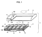
- Fig. 1 is an exploded perspective view illustrating an electric dust collector in accordance with the first exemplary embodiment of the present invention.
- electric dust collector 1 includes dust collecting unit 2 and main unit 3, in which dust collecting unit 2 is accommodated. Dust collector 1 is disposed, e.g., in an indoor unit of air conditioners. When interior air 4 passes through dust collecting unit 2, dust particles included in interior air 4 are collected, and air 4 undergoes a heat exchanger of the indoor unit, then blown out into the room again.
- Main unit 3 includes power supply 5 for powering dust collecting unit 2, which is detachable from main unit 3 with handle 6.
- Power supply 5 applies a high voltage to main unit 3 at high-voltage contact 8A through high-voltage wire 7, while a grounding voltage is applied to main unit 3 at grounding contact 10A through grounding wire 9.
- high-voltage contact 8B electrically coupled with high-voltage contact 8A of main unit 3 and grounding contact 10B coupled with grounding contact 10A are provided to dust collecting unit 2.
- Dust collecting unit 2 comprises the following elements:
- the plurality of needle-like discharge electrodes 12 are electrically connected to supporter 17 which is mounted to frame 11. Further, electrodes 12 are electrically connected to high-voltage contact 8B, and first and second grounding electrodes 13, 14 are electrically connected to each other and coupled with grounding contact 10B. Discharge electrodes 12, first and second grounding electrodes 13, 14 constitute the charging section, and the corona discharge is generated in the space among these elements.
- Honeycomb dust filter 15 is employed to form the dust collecting section because the honeycomb shape allows the sucked air to pass through with ease and realizes a high dust collection rate. Dust filter 15 is brought into contact with first grounding electrode 13. Partitions 16 are provided between respective blocks of the charging section so that the corona discharge from each one of needle-like discharge electrodes 12 cannot interfere with each other.
- Outer frame 11 integrates the charging section and the dust collecting section into one boy, and handle 6 is mounted to frame 11, so that these elements form dust-collecting unit 2. Further, dust filter 15 in the dust collecting section is detachable from other elements of dust-collecting unit 2. Thus filter 15 can be cleaned or replaced with ease when it becomes dirty due to collecting fine particles in air. If the use of the dust collector extends over a long period, simple maintainability, such as cleaning or replacement of the dust filter, is thus prepared.
- the high voltage side is negatively applied with a voltage so that the fine particles can be charged negatively; however, the high voltage side can be positively applied with a voltage so that the fine particles can be charged positively.
- the high voltage side is negatively applied with a voltage, air-ions can be negatively charged, thereby generating minusions that can relax human bodies.
- first grounding electrode 13 uses a mesh-like shape; however, any shape is usable as far as electrode 13 passes the inflow air through and the corona discharge is generated between electrode 13 and needle-like discharge electrodes 12.
- any shape is usable as far as electrode 13 passes the inflow air through and the corona discharge is generated between electrode 13 and needle-like discharge electrodes 12.
- a plate having plural openings shaping in circles or rectangles, a slit-like shape, or a cross-striped pattern is acceptable.
- a filter of honeycomb shape is used as dust filter 15; however, any shape is usable as far as filter 15 can pass the inflow air through and can be brought into contact with first grounding electrode 13. For instance, a pleated dust filter is acceptable.
- the charging section includes needle-like discharge electrodes 12 to which a high voltage is applied, first grounding electrode 13 and second grounding electrodes 14.
- the dust collecting section includes dust filter 15.
- Dust collecting unit 2 includes outer frame 11 that accommodates the charging section and the dust collecting section and integrates the two sections into one body.
- the grounding electrodes include first grounding electrode 13 brought into contact with dust filter 15 and second grounding electrodes 14 electrically connected to the first grounding electrode 13.
- dust collecting unit 2 is divided into a plurality of blocks by partitions 16, and second grounding electrodes 14 are arranged substantially parallel to needle-like discharge electrodes 12.
- Each one of second grounding electrodes 14 substantially shapes in letter "M”.
- This structure allows the corona discharge to be generated in spaces between needle-like discharge electrodes 12 and first grounding electrode 13 as well as between needle-like discharge electrodes 12 and second grounding electrodes 14. A greater discharging area can be thus created.
- Dust collecting unit 2 is partitioned into plural blocks responsive to a number of needle-like discharge electrodes 12, and second grounding electrodes 14, each of them forming an approx. letter "M", are disposed on both sides of each one of those blocks.
- Adjacent electrodes 12 thus do not interfere with each other, and the discharge from each electrode 12 can diffuse outward of dust collecting unit 2 easily with assist from second grounding electrodes 14. This mechanism charges fine particles in air efficiently when sucked air passes through the dust collecting unit, and the dust filter placed on the downstream side can collect the charged particles at a high dust collection rate.
- Fig. 2 is a perspective view illustrating a dust collecting unit in accordance with the second embodiment.
- a grounding electrode of a charging section includes first grounding electrode 13 and third grounding electrodes 19 disposed outside of tips 18 of respective needle-like discharge electrodes 12.
- First electrode 13 is electrically connected to third grounding electrodes 19.
- third grounding electrodes 19 are disposed outside of both tips 18 of electrode 12 that is placed in one of blocks and along a shorter side of unit 2. The blocks are divided along a longer side of collecting unit 2.
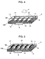
- Fig. 3 and Fig. 4 are perspective views illustrating dust collecting units in accordance with the third embodiment.
- a grounding electrode of a charging section includes first grounding electrode 13 and second grounding electrodes 20 that are made of conductive resin. Electrode 13 is electrically connected to electrodes 20.
- a grounding electrode of a charging section includes first grounding electrode 13 and third grounding electrodes 21 that are made of conductive resin. Second grounding electrodes 20 and third ones 21 both made of conductive resin are disposed on a surface of outer frame 11 of dust collecting unit 2 or integrated into outer frame 11.
- second and third grounding electrodes 20 and 21 are made of conductive resin, they are more flexible in shapes than the electrodes made of metal. Electrodes 20 and 21 can be thus disposed on the surface of outer frame 11 or integrated into outer frame 11. Further, resin is easier to handle in manufacturing. When they are integrated with frame 11, the corona discharge can prevail in entire dust collecting unit 2. As a result, an electric dust collector of a high dust collection rate is obtainable.
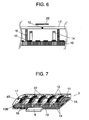
- Fig. 5 is a perspective view illustrating a dust collecting unit in accordance with the fourth embodiment
- Fig. 6 shows a sectional view taken along line A ⁇ A of Fig. 5.
- first shielding plates 22 that cover needle-like discharge electrodes 12 are provided above electrodes 12 and to outer frame 11, i.e., on the upstream side of interior air 4 flowing into dust collecting unit 2.
- Other elements of dust collecting unit 2 stay the same as described in the first embodiment.
- corona discharge is generated in spaces between needle-like discharge electrodes 12 and first grounding electrode 13 as well as between electrodes 12 and second grounding electrodes 14.
- the discharge from electrodes 12 occurs all around each electrode 12, thus parts of the discharge exist in a space on the upstream side of electrodes 12. This existence of the discharge incurs electrical noises to components placed in the space on the upstream side.
- first shielding plates 22 are provided to outer frame 11, so that the discharge from electrodes 12 to the space on the up-stream side where interior air 4 flows is suppressed. As a result, the components placed in the space on the upstream side are prevented from being charged, and a stable operation of the dust collector can be expected.
- Fig. 7 is a perspective view illustrating a dust collecting unit in accordance with the fifth embodiment
- Fig. 8 shows a sectional view taken along line A ⁇ A of Fig. 7.
- shielding walls 23 are provided to both sides of each shielding plate 22 which is described in the fourth embodiment.
- Other elements of dust collecting unit 2 stay the same as described in the first embodiment.
- corona discharge is generated in spaces between needle-like discharge electrodes 12 and first grounding electrode 13 as well as between electrodes 12 and second grounding electrodes 14. Parts of the discharge exist also in spaces on the upstream side and lateral sides of discharge electrodes 12.
- Shielding walls 23 are provided to both sides of each electrode 12 in addition to first shielding plate 22, so that the discharge from electrodes 12 to the space on the upper stream side, where interior air 4 flows, is suppressed by those shielding plates and walls. As a result, the components placed in the space on the upstream side are prevented from being charged, and a stable operation of the dust collector can be expected.
- Fig. 9 is a sectional view of a dust collecting unit in accordance with the sixth embodiment.
- tips of needle-like discharge electrodes 12 are bent toward first grounding electrode 13, and these bent tips work as needle-like discharge electrodes 24.
- Other elements of dust collecting unit 2 stay the same as demonstrated in the first embodiment.
- Corona discharge is generated in spaces between bent needle-like discharge electrodes 24 and first grounding electrode 13 as well as between electrodes 24 and second grounding electrodes 14.
- the discharge from electrodes 24 to spaces on the upstream side is suppressed because the tips of needle-like electrodes are bent toward a reversal side to the air-sucking side.
- other members disposed in a space on the upstream side are restrained from being charged.
- Fig. 10 is a sectional view of a dust collecting unit in accordance with the seventh embodiment.
- tips of needle-like discharge electrodes 12 are bent toward first grounding electrode 13, and these bent tips work as needle-like discharge electrodes 24. Hitherto is the same as the sixth embodiment.
- Second shielding plates 25 are additionally provided to vicinities of tip-ends of electrodes 24. Shielding plates 25 are bonded to electrodes 24. Other elements of dust collecting unit 2 stay the same as demonstrated in the first embodiment.
- Corona discharge is generated between electrodes 24 and first grounding electrode 13 as well as between electrodes 24 and second grounding electrodes 14.
- the discharge from electrodes 24 to the space on the upstream side is suppressed by second shielding plates 25.
- other members disposed in a space on the upstream side of the air sucking side are restrained from being charged.
- the present invention uses those dust collectors demonstrated in the previous embodiments in blowers.
- Electric dust collector 1 comprising dust collecting unit 2 and main unit 3 is disposed in an air-flow path of a blower that comprises a blowing fan and the air-flow pass, so that an air conditioner or an air purifier is formed.
- the electric dust collector of the present invention can diffuse the discharge into the entire dust collector, therefore, the use of this dust collector realizes a simply constructed air conditioner or air purifier having a substantially small draft loss therethrough and no adversely influence to other electronic devices.
- the air conditioner or air purifier that employs the electric dust collector of the present invention also features a high dust collection rate.
- a charging section is formed of (1) needle-like discharge electrodes, to which a high voltage is applied, and (2) a grounding electrode.
- a dust collecting section is formed of (3) a dust collector, and (4) an outer frame accommodates and integrates the charging section and the dust collecting section into a dust collecting unit.
- the grounding electrode is formed of (5) first grounding electrode brought into contact with the dust filter and (6) second grounding electrodes surrounding the needle-like discharge electrodes and being electrically connected to the first grounding electrode.
- This structure generates corona discharge in the charging section between the needle-like discharge electrodes and the first grounding electrode as well as between the needle-like discharge electrodes and the second grounding electrodes.
- the corona discharge is generated in a greater area, so that when sucked air passes through the dust collecting unit, fine particles in air are charged efficiently.
- the dust filter disposed on the downstream side can collect the charged particles at a high dust collection rate.
Landscapes
- Electrostatic Separation (AREA)
- Air Filters, Heat-Exchange Apparatuses, And Housings Of Air-Conditioning Units (AREA)
Applications Claiming Priority (2)
| Application Number | Priority Date | Filing Date | Title |
|---|---|---|---|
| JP2001263260A JP3818101B2 (ja) | 2001-08-31 | 2001-08-31 | 電気集塵装置およびそれを用いた送風装置 |
| JP2001263260 | 2001-08-31 |
Publications (3)
| Publication Number | Publication Date |
|---|---|
| EP1291086A2 true EP1291086A2 (de) | 2003-03-12 |
| EP1291086A3 EP1291086A3 (de) | 2005-11-23 |
| EP1291086B1 EP1291086B1 (de) | 2010-09-15 |
Family
ID=19090044
Family Applications (1)
| Application Number | Title | Priority Date | Filing Date |
|---|---|---|---|
| EP02015541A Expired - Lifetime EP1291086B1 (de) | 2001-08-31 | 2002-07-11 | Elektroabscheider und Gebläse mit derselben |
Country Status (6)
| Country | Link |
|---|---|
| EP (1) | EP1291086B1 (de) |
| JP (1) | JP3818101B2 (de) |
| KR (2) | KR100869628B1 (de) |
| CN (2) | CN2613317Y (de) |
| ES (1) | ES2350682T3 (de) |
| MY (1) | MY168533A (de) |
Cited By (8)
| Publication number | Priority date | Publication date | Assignee | Title |
|---|---|---|---|---|
| EP1629894A1 (de) * | 2004-08-31 | 2006-03-01 | Matsushita Electric Industrial Co., Ltd. | Elektro-Abscheider, und Klimaanlage und Luftreiniger mit einem solchen Abscheider |
| EP1629895A1 (de) * | 2004-08-31 | 2006-03-01 | Matsushita Electrical Industrial Co., Ltd | Elektro-Abscheider, und Klimaanlage und Luftreiniger mit einem solchen Abscheider |
| KR100869628B1 (ko) * | 2001-08-31 | 2008-11-21 | 파나소닉 주식회사 | 전기 집진 장치 |
| EP2039432A4 (de) * | 2006-06-15 | 2010-08-25 | Daikin Ind Ltd | Staubsammler |
| EP2052782A4 (de) * | 2006-07-20 | 2012-11-21 | Daikin Ind Ltd | Staubfangvorrichtung |
| WO2013181290A1 (en) * | 2012-05-29 | 2013-12-05 | Tessera, Inc. | Electrohydrodynamic (ehd) fluid mover with field blunting structures in flow channel for spatially selective suppression of ion generation |
| SE1950823A1 (en) * | 2019-06-28 | 2020-12-29 | Cabinair Sweden Ab | Air purification device |
| US12044438B2 (en) | 2020-05-15 | 2024-07-23 | Genano Oy | Air purifying device, arrangement and method for separating materials from a gas flow |
Families Citing this family (8)
| Publication number | Priority date | Publication date | Assignee | Title |
|---|---|---|---|---|
| JP4830317B2 (ja) * | 2005-03-08 | 2011-12-07 | パナソニック株式会社 | 電気集塵ユニット |
| JP2007107803A (ja) * | 2005-10-13 | 2007-04-26 | Matsushita Electric Ind Co Ltd | 空気調和機 |
| KR100749054B1 (ko) | 2005-10-25 | 2007-08-13 | 삼성전자주식회사 | 공기조화기 |
| US9250162B2 (en) | 2013-08-09 | 2016-02-02 | Ut-Battelle, Llc | Direct impact aerosol sampling by electrostatic precipitation |
| KR20170051893A (ko) | 2015-11-03 | 2017-05-12 | 현대자동차주식회사 | 전기식 집진필터 |
| KR101669391B1 (ko) | 2016-02-04 | 2016-10-25 | 주식회사 엔아이티코리아 | 전기 집진필터 제조방법 및 그 방법에 의해 제조된 전기 집진필터 |
| CN109772587A (zh) * | 2019-01-22 | 2019-05-21 | 厚联环境科技(上海)有限公司 | 一种电集一体集尘材料及净化装置 |
| US12409461B2 (en) * | 2020-09-24 | 2025-09-09 | Creative Technology Corporation | Dust collector and dust collection method |
Family Cites Families (12)
| Publication number | Priority date | Publication date | Assignee | Title |
|---|---|---|---|---|
| GB626189A (en) * | 1940-09-03 | 1949-07-11 | American Air Filter Co | Improvements in or relating to electric gas cleaners |
| US4744910A (en) * | 1986-04-22 | 1988-05-17 | Voyager Technologies, Inc. | Electrostatic filter |
| JPH02251257A (ja) * | 1989-03-23 | 1990-10-09 | Mitsubishi Electric Corp | 空気清浄機 |
| JPH03296453A (ja) * | 1990-04-12 | 1991-12-27 | Matsushita Seiko Co Ltd | 空気清浄機 |
| US5403383A (en) * | 1992-08-26 | 1995-04-04 | Jaisinghani; Rajan | Safe ionizing field electrically enhanced filter and process for safely ionizing a field of an electrically enhanced filter |
| US5549735C1 (en) * | 1994-06-09 | 2001-08-14 | Coppom Technologies | Electrostatic fibrous filter |
| KR100201651B1 (ko) * | 1995-06-20 | 1999-06-15 | 구자홍 | 공기정화기의 전기 집진 필터 |
| JPH11104516A (ja) * | 1997-10-07 | 1999-04-20 | Calsonic Corp | 静電式空気清浄機 |
| JP3360582B2 (ja) * | 1997-10-15 | 2002-12-24 | ダイキン工業株式会社 | 空気清浄装置の集塵エレメント |
| JPH11151452A (ja) * | 1997-11-20 | 1999-06-08 | Midori Anzen Co Ltd | 電気集塵装置 |
| KR200178327Y1 (ko) * | 1999-11-16 | 2000-04-15 | 김장하 | 음이온 발생식 공기 청정기 |
| JP3818101B2 (ja) * | 2001-08-31 | 2006-09-06 | 松下電器産業株式会社 | 電気集塵装置およびそれを用いた送風装置 |
-
2001
- 2001-08-31 JP JP2001263260A patent/JP3818101B2/ja not_active Expired - Fee Related
-
2002
- 2002-07-11 EP EP02015541A patent/EP1291086B1/de not_active Expired - Lifetime
- 2002-07-11 ES ES02015541T patent/ES2350682T3/es not_active Expired - Lifetime
- 2002-07-23 MY MYPI20022770A patent/MY168533A/en unknown
- 2002-08-30 CN CNU022518061U patent/CN2613317Y/zh not_active Expired - Fee Related
- 2002-08-30 KR KR1020020051907A patent/KR100869628B1/ko not_active Expired - Fee Related
- 2002-08-30 CN CNB021414629A patent/CN1257775C/zh not_active Expired - Fee Related
-
2008
- 2008-09-19 KR KR1020080092219A patent/KR100914364B1/ko not_active Expired - Fee Related
Cited By (11)
| Publication number | Priority date | Publication date | Assignee | Title |
|---|---|---|---|---|
| KR100869628B1 (ko) * | 2001-08-31 | 2008-11-21 | 파나소닉 주식회사 | 전기 집진 장치 |
| EP1629894A1 (de) * | 2004-08-31 | 2006-03-01 | Matsushita Electric Industrial Co., Ltd. | Elektro-Abscheider, und Klimaanlage und Luftreiniger mit einem solchen Abscheider |
| EP1629895A1 (de) * | 2004-08-31 | 2006-03-01 | Matsushita Electrical Industrial Co., Ltd | Elektro-Abscheider, und Klimaanlage und Luftreiniger mit einem solchen Abscheider |
| EP2039432A4 (de) * | 2006-06-15 | 2010-08-25 | Daikin Ind Ltd | Staubsammler |
| US8192535B2 (en) | 2006-06-15 | 2012-06-05 | Daikin Industries, Ltd. | Dust collector |
| EP2052782A4 (de) * | 2006-07-20 | 2012-11-21 | Daikin Ind Ltd | Staubfangvorrichtung |
| WO2013181290A1 (en) * | 2012-05-29 | 2013-12-05 | Tessera, Inc. | Electrohydrodynamic (ehd) fluid mover with field blunting structures in flow channel for spatially selective suppression of ion generation |
| SE1950823A1 (en) * | 2019-06-28 | 2020-12-29 | Cabinair Sweden Ab | Air purification device |
| SE544046C2 (en) * | 2019-06-28 | 2021-11-16 | Cabinair Sweden Ab | Air purification device with a filter medium comprising a conductive material |
| EP3990191A4 (de) * | 2019-06-28 | 2023-07-19 | CabinAir Sweden AB | Luftreinigungsvorrichtung |
| US12044438B2 (en) | 2020-05-15 | 2024-07-23 | Genano Oy | Air purifying device, arrangement and method for separating materials from a gas flow |
Also Published As
| Publication number | Publication date |
|---|---|
| KR20080098567A (ko) | 2008-11-11 |
| JP2003071321A (ja) | 2003-03-11 |
| ES2350682T3 (es) | 2011-01-26 |
| CN1257775C (zh) | 2006-05-31 |
| KR100914364B1 (ko) | 2009-08-28 |
| CN2613317Y (zh) | 2004-04-28 |
| EP1291086B1 (de) | 2010-09-15 |
| CN1406671A (zh) | 2003-04-02 |
| EP1291086A3 (de) | 2005-11-23 |
| KR100869628B1 (ko) | 2008-11-21 |
| KR20030019252A (ko) | 2003-03-06 |
| MY168533A (en) | 2018-11-12 |
| JP3818101B2 (ja) | 2006-09-06 |
Similar Documents
| Publication | Publication Date | Title |
|---|---|---|
| KR100914364B1 (ko) | 전기 집진 장치 및 그것을 이용한 송풍 장치 | |
| KR101989098B1 (ko) | 집진장치 | |
| KR20040056135A (ko) | 공기 정화기 | |
| US7090717B2 (en) | Air purifier | |
| CN111318372B (zh) | 具有使用碳纤维的静电集尘装置的电器 | |
| JP4853604B2 (ja) | 空気調和機 | |
| US7141098B2 (en) | Air filtration system using point ionization sources | |
| US6758884B2 (en) | Air filtration system using point ionization sources | |
| JP2007007589A (ja) | 電気集塵デバイス及びこれを組込んだ空気清浄装置 | |
| JP4451740B2 (ja) | 空気清浄器及び空気調和機 | |
| JP2022147333A (ja) | 荷電装置及び空気清浄機 | |
| JP2006068580A (ja) | 電気集塵装置およびそれを用いた空気調和装置または空気洗浄装置 | |
| JP2006068581A (ja) | 電気集塵装置およびそれを用いた空気調和装置または空気清浄装置 | |
| JP2002136893A (ja) | エアクリーナー | |
| JPS59209664A (ja) | 送風装置 | |
| JP2006125802A (ja) | 空気調和機 | |
| JP2006132928A (ja) | 空気調和機 | |
| CN210373804U (zh) | 静电除尘模块和空气处理装置 | |
| JPH09327636A (ja) | 空気調和機 | |
| JP2007107805A (ja) | 空気調和機 | |
| JP4465765B2 (ja) | 空気清浄器 | |
| JP6508356B2 (ja) | 放電デバイス及びこれを備えた空気調和装置 | |
| JP3426967B2 (ja) | 空気清浄機用放電電極 | |
| JP2005270980A (ja) | 電気集塵装置およびそれを用いた送風装置 | |
| JPH07853A (ja) | 空気清浄装置及びそれを有するファンヒーター |
Legal Events
| Date | Code | Title | Description |
|---|---|---|---|
| PUAI | Public reference made under article 153(3) epc to a published international application that has entered the european phase |
Free format text: ORIGINAL CODE: 0009012 |
|
| AK | Designated contracting states |
Kind code of ref document: A2 Designated state(s): AT BE BG CH CY CZ DE DK EE ES FI FR GB GR IE IT LI LU MC NL PT SE SK TR |
|
| AX | Request for extension of the european patent |
Extension state: AL LT LV MK RO SI |
|
| PUAL | Search report despatched |
Free format text: ORIGINAL CODE: 0009013 |
|
| AK | Designated contracting states |
Kind code of ref document: A3 Designated state(s): AT BE BG CH CY CZ DE DK EE ES FI FR GB GR IE IT LI LU MC NL PT SE SK TR |
|
| AX | Request for extension of the european patent |
Extension state: AL LT LV MK RO SI |
|
| RIC1 | Information provided on ipc code assigned before grant |
Ipc: 7B 03C 3/45 B Ipc: 7B 03C 3/66 A Ipc: 7B 03C 3/08 B Ipc: 7B 03C 3/09 B |
|
| 17P | Request for examination filed |
Effective date: 20060206 |
|
| AKX | Designation fees paid |
Designated state(s): ES GR IT |
|
| REG | Reference to a national code |
Ref country code: DE Ref legal event code: 8566 |
|
| 17Q | First examination report despatched |
Effective date: 20060424 |
|
| RAP1 | Party data changed (applicant data changed or rights of an application transferred) |
Owner name: PANASONIC CORPORATION |
|
| GRAP | Despatch of communication of intention to grant a patent |
Free format text: ORIGINAL CODE: EPIDOSNIGR1 |
|
| GRAS | Grant fee paid |
Free format text: ORIGINAL CODE: EPIDOSNIGR3 |
|
| GRAA | (expected) grant |
Free format text: ORIGINAL CODE: 0009210 |
|
| AK | Designated contracting states |
Kind code of ref document: B1 Designated state(s): ES GR IT |
|
| REG | Reference to a national code |
Ref country code: GR Ref legal event code: EP Ref document number: 20100402498 Country of ref document: GR |
|
| REG | Reference to a national code |
Ref country code: ES Ref legal event code: FG2A Effective date: 20110114 |
|
| PLBE | No opposition filed within time limit |
Free format text: ORIGINAL CODE: 0009261 |
|
| STAA | Information on the status of an ep patent application or granted ep patent |
Free format text: STATUS: NO OPPOSITION FILED WITHIN TIME LIMIT |
|
| PGFP | Annual fee paid to national office [announced via postgrant information from national office to epo] |
Ref country code: GR Payment date: 20110620 Year of fee payment: 10 |
|
| 26N | No opposition filed |
Effective date: 20110616 |
|
| PGFP | Annual fee paid to national office [announced via postgrant information from national office to epo] |
Ref country code: IT Payment date: 20120713 Year of fee payment: 11 Ref country code: ES Payment date: 20120731 Year of fee payment: 11 |
|
| REG | Reference to a national code |
Ref country code: GR Ref legal event code: ML Ref document number: 20100402498 Country of ref document: GR Effective date: 20130104 |
|
| PG25 | Lapsed in a contracting state [announced via postgrant information from national office to epo] |
Ref country code: GR Free format text: LAPSE BECAUSE OF NON-PAYMENT OF DUE FEES Effective date: 20130204 |
|
| PG25 | Lapsed in a contracting state [announced via postgrant information from national office to epo] |
Ref country code: IT Free format text: LAPSE BECAUSE OF NON-PAYMENT OF DUE FEES Effective date: 20130711 |
|
| REG | Reference to a national code |
Ref country code: ES Ref legal event code: FD2A Effective date: 20140905 |
|
| PG25 | Lapsed in a contracting state [announced via postgrant information from national office to epo] |
Ref country code: ES Free format text: LAPSE BECAUSE OF NON-PAYMENT OF DUE FEES Effective date: 20130712 |