EP1290981B1 - Herzkatheter mit optimierter Sonde - Google Patents
Herzkatheter mit optimierter Sonde Download PDFInfo
- Publication number
- EP1290981B1 EP1290981B1 EP02018800A EP02018800A EP1290981B1 EP 1290981 B1 EP1290981 B1 EP 1290981B1 EP 02018800 A EP02018800 A EP 02018800A EP 02018800 A EP02018800 A EP 02018800A EP 1290981 B1 EP1290981 B1 EP 1290981B1
- Authority
- EP
- European Patent Office
- Prior art keywords
- probe
- probe body
- catheter according
- heart catheter
- electrodes
- Prior art date
- Legal status (The legal status is an assumption and is not a legal conclusion. Google has not performed a legal analysis and makes no representation as to the accuracy of the status listed.)
- Expired - Lifetime
Links
- 239000000523 sample Substances 0.000 claims description 80
- 239000013307 optical fiber Substances 0.000 claims description 23
- 230000000747 cardiac effect Effects 0.000 claims description 14
- 239000000835 fiber Substances 0.000 claims description 9
- 230000001575 pathological effect Effects 0.000 claims description 7
- 239000008280 blood Substances 0.000 claims description 6
- 210000004369 blood Anatomy 0.000 claims description 6
- 239000012530 fluid Substances 0.000 claims description 2
- 230000002262 irrigation Effects 0.000 claims 1
- 238000003973 irrigation Methods 0.000 claims 1
- 230000004807 localization Effects 0.000 claims 1
- 239000000463 material Substances 0.000 claims 1
- 210000001174 endocardium Anatomy 0.000 description 4
- 239000002504 physiological saline solution Substances 0.000 description 4
- 239000007788 liquid Substances 0.000 description 3
- 208000027418 Wounds and injury Diseases 0.000 description 2
- 230000036772 blood pressure Effects 0.000 description 2
- 230000006378 damage Effects 0.000 description 2
- 238000011010 flushing procedure Methods 0.000 description 2
- 238000010438 heat treatment Methods 0.000 description 2
- 208000014674 injury Diseases 0.000 description 2
- 238000004519 manufacturing process Methods 0.000 description 2
- 238000013021 overheating Methods 0.000 description 2
- 239000000243 solution Substances 0.000 description 2
- 238000004873 anchoring Methods 0.000 description 1
- 229940030225 antihemorrhagics Drugs 0.000 description 1
- 230000006793 arrhythmia Effects 0.000 description 1
- 206010003119 arrhythmia Diseases 0.000 description 1
- 238000010009 beating Methods 0.000 description 1
- 230000015572 biosynthetic process Effects 0.000 description 1
- 210000004204 blood vessel Anatomy 0.000 description 1
- 230000015271 coagulation Effects 0.000 description 1
- 238000005345 coagulation Methods 0.000 description 1
- 238000001816 cooling Methods 0.000 description 1
- 230000001419 dependent effect Effects 0.000 description 1
- 239000013013 elastic material Substances 0.000 description 1
- 238000005755 formation reaction Methods 0.000 description 1
- 230000000025 haemostatic effect Effects 0.000 description 1
- 230000002439 hemostatic effect Effects 0.000 description 1
- 238000003780 insertion Methods 0.000 description 1
- 230000037431 insertion Effects 0.000 description 1
- 210000004165 myocardium Anatomy 0.000 description 1
- 230000035515 penetration Effects 0.000 description 1
- 230000035945 sensitivity Effects 0.000 description 1
Images

Classifications
-
- A—HUMAN NECESSITIES
- A61—MEDICAL OR VETERINARY SCIENCE; HYGIENE
- A61B—DIAGNOSIS; SURGERY; IDENTIFICATION
- A61B5/00—Measuring for diagnostic purposes; Identification of persons
- A61B5/24—Detecting, measuring or recording bioelectric or biomagnetic signals of the body or parts thereof
- A61B5/25—Bioelectric electrodes therefor
- A61B5/279—Bioelectric electrodes therefor specially adapted for particular uses
- A61B5/28—Bioelectric electrodes therefor specially adapted for particular uses for electrocardiography [ECG]
- A61B5/283—Invasive
- A61B5/287—Holders for multiple electrodes, e.g. electrode catheters for electrophysiological study [EPS]
-
- A—HUMAN NECESSITIES
- A61—MEDICAL OR VETERINARY SCIENCE; HYGIENE
- A61B—DIAGNOSIS; SURGERY; IDENTIFICATION
- A61B18/00—Surgical instruments, devices or methods for transferring non-mechanical forms of energy to or from the body
- A61B18/18—Surgical instruments, devices or methods for transferring non-mechanical forms of energy to or from the body by applying electromagnetic radiation, e.g. microwaves
- A61B18/20—Surgical instruments, devices or methods for transferring non-mechanical forms of energy to or from the body by applying electromagnetic radiation, e.g. microwaves using laser
- A61B18/22—Surgical instruments, devices or methods for transferring non-mechanical forms of energy to or from the body by applying electromagnetic radiation, e.g. microwaves using laser the beam being directed along or through a flexible conduit, e.g. an optical fibre; Couplings or hand-pieces therefor
- A61B18/24—Surgical instruments, devices or methods for transferring non-mechanical forms of energy to or from the body by applying electromagnetic radiation, e.g. microwaves using laser the beam being directed along or through a flexible conduit, e.g. an optical fibre; Couplings or hand-pieces therefor with a catheter
-
- A—HUMAN NECESSITIES
- A61—MEDICAL OR VETERINARY SCIENCE; HYGIENE
- A61N—ELECTROTHERAPY; MAGNETOTHERAPY; RADIATION THERAPY; ULTRASOUND THERAPY
- A61N1/00—Electrotherapy; Circuits therefor
- A61N1/02—Details
- A61N1/04—Electrodes
- A61N1/05—Electrodes for implantation or insertion into the body, e.g. heart electrode
- A61N1/056—Transvascular endocardial electrode systems
- A61N1/057—Anchoring means; Means for fixing the head inside the heart
- A61N1/0573—Anchoring means; Means for fixing the head inside the heart chacterised by means penetrating the heart tissue, e.g. helix needle or hook
- A61N1/0575—Anchoring means; Means for fixing the head inside the heart chacterised by means penetrating the heart tissue, e.g. helix needle or hook with drug delivery
-
- A—HUMAN NECESSITIES
- A61—MEDICAL OR VETERINARY SCIENCE; HYGIENE
- A61B—DIAGNOSIS; SURGERY; IDENTIFICATION
- A61B17/00—Surgical instruments, devices or methods
- A61B2017/00017—Electrical control of surgical instruments
- A61B2017/00022—Sensing or detecting at the treatment site
- A61B2017/00039—Electric or electromagnetic phenomena other than conductivity, e.g. capacity, inductivity, Hall effect
- A61B2017/00044—Sensing electrocardiography, i.e. ECG
-
- A—HUMAN NECESSITIES
- A61—MEDICAL OR VETERINARY SCIENCE; HYGIENE
- A61B—DIAGNOSIS; SURGERY; IDENTIFICATION
- A61B18/00—Surgical instruments, devices or methods for transferring non-mechanical forms of energy to or from the body
- A61B2018/00005—Cooling or heating of the probe or tissue immediately surrounding the probe
- A61B2018/00011—Cooling or heating of the probe or tissue immediately surrounding the probe with fluids
- A61B2018/00029—Cooling or heating of the probe or tissue immediately surrounding the probe with fluids open
Definitions
- the invention relates to a cardiac catheter, in particular for the treatment of subendocardial arrhythmia, with a tubular guide catheter, in which a probe for locating pathological areas is movable and perpendicular to the heart wall can be placed.
- Such cardiac catheters are used to attenuate or interrupt conduction in pathological areas of a cardiac wall.
- the heart catheter uses the principle of contactless laser irradiation to generate deep-reaching coagulation necroses in the myocardium (heart wall).
- the laser irradiation in particular has the advantage that no overheating, charring or cratering formations, e.g. with an HF catheter (HF: high frequency), occur in the treated tissue.
- HF high frequency
- the generic cardiac catheter has a probe which is placed perpendicular to the tissue to be treated and held by means of an optical fiber at a distance from the tissue surface.
- From the DE3718139C1 is the basic principle of a cardiac catheter with a probe for vertical laser application known.
- the probe shown has several sensors (electrodes), which are anchored in the heart wall and serve to dissipate electrical potentials. In this design of the electrodes, however, there is a risk of puncturing or slitting the insides of the heart.
- Another heart catheter with vertical probe is in the U.S. Patent 5,500,012 described.
- This probe has two rod-shaped, protruding electrodes that penetrate into the inner heart wall until the distal tip of an optical fiber rests against the inner heart wall.
- the disadvantage is In this case, the small contact surface of the electrodes, the small distance between the electrodes to each other and the resulting poor resolution of the electrical potentials. Due to the direct contact of the fiber tip with the tissue and the lack of cooling holes are usually created in the heart wall.
- a cardiac catheter is known with a probe, which largely keeps the blood stream present in the heart by means of a tent-like shielding from the irradiation room.
- the cardiac catheter includes a tubular guide catheter and a flexible guide tube for moving a probe within the guide catheter.
- the probe body also does not include an optical fiber receptacle in which the optical fiber can be secured at a defined distance from the tissue. Between the electrodes of the probe, a film is stretched, which defines a relatively protected irradiation space.
- this arrangement is relatively unstable and unable to sufficiently withstand the pressure conditions prevailing in the heart.
- the production of this probe is relatively complicated.
- the WO-A-01 / 39,682 discloses a cardiac catheter having a probe and an optical fiber, wherein the probe body has a distal portion with a cavity in which the light emitted by the optical fiber can propagate to the tissue to be treated.
- this catheter is not suitable for moving it through narrow and highly curved blood vessels.
- the US-A-6,143,019 also discloses a cardiac catheter with an optical fiber.
- the optical fiber of the US-A-6,143,019 is relative to the catheter hose movable.
- the heart catheter according to the invention comprises a tubular guide catheter and a probe for locating the areas to be treated, which is placed perpendicular to the surface to be treated, the probe having a probe body with an optical fiber receptacle. Furthermore, the heart catheter according to the invention comprises an actuating device for pushing and pushing the probe in the axial direction of the guide catheter, as well as an optical fiber which is mounted in the probe body.
- the essential idea of the invention is to form the distal section of the probe body with a cavity which is open or transparent to the tissue, which is surrounded on the circumference by a substantially non-flexible wall and which preferably has a larger cross-section than the receptacle for the optical Fiber.
- the surrounding wall of the distal portion of the cavity is so stably formed that it readily withstands the external blood pressure and the pressure of the beating heart and is able to keep the blood out of the space around the distal end of the fiber so that the emitted light unhindered in the cavity can spread. This can be prevented that the distal probe edge is pressed into the beam path, which would cause charring.
- the probe preferably comprises one or more electrodes. These could also be attached to the outer guide catheter.
- the probe body is preferably formed in one piece and comprises a proximal and the distal portion.
- the proximal portion is preferably for connection to the actuator, the distal portion is dimensioned so that the light emitted by the fiber in the cavity, which simultaneously forms a treatment space, can conically spread to the tissue as the fiber tip is spaced from the tissue is arranged.
- a physiological solution in particular physiological saline solution, is preferably flushed into the cavity.
- the probe body and in particular the distal end of the probe body may have openings, such as e.g. Have notches through which the flushing liquid can escape.
- the probe body comprises a plurality, in particular three, electrodes, which are preferably fastened on the outer circumference of the distal section. Due to the large distance between the electrodes from each other, the sensitivity of the probe is improved and achieves a high significance of the ECG curves derived from the electrodes.
- the electrodes are preferably not formed flexible and therefore allow a stable positioning of the probe on the endocardium.
- the electrodes protrude not or only slightly (preferably less than 0.5 mm, in particular 0.2 or 0.1 mm) beyond the distal end of the probe body. A violation of the endocardium by the electrodes is thus almost impossible.
- the electrodes are preferably platelet-shaped and are preferably located on the outside of the distal portion of the probe body. Relative to rod-shaped electrodes, this results in a relatively wide-area contact with the heart wall and thus a greatly reduced risk of injury.
- the flat positioning of the electrodes which are also recessed in recesses mounted and flush with the outer wall of the distal portion, also allows easy insertion of the probe through introducer sheaths, guide catheter or hemostatic valves.
- the distal ends of the electrodes can be corrugated or corrugated, whereby an even better anchoring of the probe can be achieved.
- the probe body has one or more passages for supplying flushing liquid into the cavity.
- the probe body itself is preferably made of a non-elastic material, e.g. Plastic and is preferably formed in one piece.
- the actuator is a flexible tube attached to the proximal portion of the probe body.
- the proximal portion of the probe body is dimensioned so that it can be inserted into the tube and connected to this, in particular glued.
- the hose also serves to supply rinsing fluid into the cavity.
- the tube preferably terminates flush with the probe on its outer circumference.
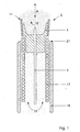
- FIG. 1 the distal end of a cardiac catheter is shown in section.
- the cardiac catheter comprises a guide catheter 18, in which a probe S in the axial direction (arrow A) is arranged displaceably.
- the treatment of pathological areas takes place in that the probe S is placed vertically on the area to be treated and the tissue is irradiated by means of laser light.
- the probe S is actuated via a plastic tube 17, which is attached to a proximal portion 2 of the probe S.
- physiological saline solution 16 is passed through the tube 17 and passages 15 in the probe body 1 into the treatment space 13.
- the distal edge 20 of the probe body 1 is provided with notches 14.
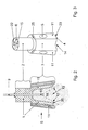
- the structure of an exemplary probe S is in FIG. 2 shown in more detail.
- the probe S consists of a one-piece probe body 1 (preferably made of plastic) with a proximal portion 2 and a distal portion 3, wherein the proximal portion 2 has a smaller cross-section than the proximal portion 3.
- the probe body 1 has a central opening 8 for a optical fiber 9, the tip 10 of which projects into the cavity 13.
- the probe body 1 has an opening at the distal end or at least translucent to the tissue.
- the surrounding wall of the distal portion of the cavity is so stably formed that it readily withstands the external blood pressure and is able to keep the blood out of the space around the distal end of the fiber so that the emitted light can propagate unhindered in the cavity.
- the tip 10 of the optical fiber 9 is fixed in the probe body 1 and is therefore always kept at a defined distance from the tissue when the probe is placed on.
- the cross section of the cavity 13 is substantially larger and in particular at least twice as large as the cross section of the opening 8 for the optical fiber 9.
- the axial extent of the wall 19 is dimensioned such that the light emitted from the tip 10 of the optical fiber 9 -
- the light cone is denoted by 12 - can propagate unhindered without hitting the distal edge 20 of the probe body 1.
- the probe body 1 further comprises three plate-shaped electrodes 11, which are arranged in recesses 4 on the outer periphery of the distal portion 3.
- the electrodes 11 terminate flush with the surface of the distal section 3 on the outside. This ensures unhindered pushing through the probe through introducer sheaths, guide catheters or haemostatic valves.
- the tube 17 attached to the proximal portion 2 preferably also terminates flush with the outer surface of the distal portion 3.
- the electrodes 11 protrude only slightly beyond the distal edge 20 of the proximal portion 3. In this case, they are arranged in particular such that they are not irradiated by the laser light. Excessive heating of the electrodes 11 is thus excluded.
- FIG. 3 shows a side view of the probe body 1 of FIG. 2 in which the recesses 4 and attachment points 5 for the electrodes 11 are clearly visible.
- the attachment points 5 serve to secure the electrodes 11, which have corresponding openings. By heat treatment, the electrodes 11 are finally fixed.
- an additional recess 25 is provided.
- the proximal portion 2 comprises a plurality of passages 15 for supplying physiological saline solution into the cavity 13, which are divided by web walls 6.
- a projection 22 for receiving the optical fiber 9 is further formed, which protrudes slightly beyond the proximal portion 2.
- FIG. 4 shows a plan view of the probe body 1 of FIG. 2 , As can be seen, three passages 15 are provided for the supply of physiological saline, which are divided by three web walls 6. The projection 22 with the receptacle 8 extends in the middle of the probe body. 1
- FIG. 5 shows a side view of a plate-shaped electrode 11 with a circular opening 24 which is placed on a mounting point 5.
- the platelet electrode 11 has a corrugated distal edge 23 which prevents the probe from slipping on the tissue.
- FIG. 6 is a plan view of the electrode of FIG. 5 shown.
- the electrode 11 is curved substantially in the shape of a ring segment and thus has a relatively wide contact surface. Because of the placement of the electrodes 11 projecting only slightly beyond the edge 20 and their wide-area contact with the heart wall, the risk of injury during application is greatly reduced.
Landscapes
- Health & Medical Sciences (AREA)
- Life Sciences & Earth Sciences (AREA)
- Engineering & Computer Science (AREA)
- Cardiology (AREA)
- Heart & Thoracic Surgery (AREA)
- Animal Behavior & Ethology (AREA)
- Surgery (AREA)
- Physics & Mathematics (AREA)
- Veterinary Medicine (AREA)
- Biomedical Technology (AREA)
- Public Health (AREA)
- General Health & Medical Sciences (AREA)
- Molecular Biology (AREA)
- Medical Informatics (AREA)
- Nuclear Medicine, Radiotherapy & Molecular Imaging (AREA)
- Bioinformatics & Cheminformatics (AREA)
- Chemical & Material Sciences (AREA)
- Medicinal Chemistry (AREA)
- Biophysics (AREA)
- Pathology (AREA)
- Vascular Medicine (AREA)
- Radiology & Medical Imaging (AREA)
- Physiology (AREA)
- Optics & Photonics (AREA)
- Electromagnetism (AREA)
- Otolaryngology (AREA)
- Laser Surgery Devices (AREA)
- Media Introduction/Drainage Providing Device (AREA)
- Surgical Instruments (AREA)
- Measurement And Recording Of Electrical Phenomena And Electrical Characteristics Of The Living Body (AREA)
Description
- Die Erfindung betrifft einen Herzkatheter, insbesondere zur Behandlung subendokardialer Arrhythmie, mit einem schlauchförmigen Führungskatheter, in dem eine Sonde zum Lokalisieren pathologischer Areale bewegbar und senkrecht auf die Herzwand aufsetzbar ist.
- Derartige Herzkatheter werden dazu verwendet, die Reizleitung in pathologischen Bereichen einer Herzwand abzuschwächen oder zu unterbrechen. Dabei nutzt der Herzkatheter das Prinzip der kontaktlosen Laserbestrahlung zur Erzeugung tiefreichender Koagulationsnekrosen im Myokard (Herzwand). Die Laserbestrahlung hat insbesondere den Vorteil hat, dass keine Überhitzungen, Verkohlungen oder Kraterbildungen, wie z.B. bei einem HF-Katheter (HF: Hochfrequenz), im behandelten Gewebe auftreten.
- Der gattungsgemäße Herzkatheter hat eine Sonde, die senkrecht auf das zu behandelnde Gewebe aufgesetzt und mittels der eine optische Faser in Abstand zur Gewebeoberfläche gehalten wird. Aus der
DE3718139C1 ist das grundlegende Prinzip eines Herzkatheters mit einer Sonde für senkrechte Laserapplikation bekannt. Die dargestellte Sonde hat mehrere Fühler (Elektroden), die in der Herzwand verankert werden und zur Ableitung elektrischer Potentiale dienen. Bei dieser Gestaltung der Elektroden besteht jedoch die Gefahr, die Herzinnenhaut zu durchstechen oder aufzuschlitzen. - Ein anderer Herzkatheter mit senkrecht aufgesetzter Sonde ist in der
US-Patentschrift 5,500,012 beschrieben. Diese Sonde hat zwei stabförmige, nach vorne ragende Elektroden, die in die Herzinnenwand eindringen, bis die distale Spitze einer optischen Faser an der Herzinnenwand anliegt. Nachteilig ist dabei die kleine Kontaktfläche der Elektroden, der geringe Abstand der Elektroden zueinander und die dadurch bedingte schlechte Auflösung der elektrischen Potentiale. Wegen des unmittelbaren Kontakts der Faserspitze mit dem Gewebe und der fehlenden Kühlung werden in der Regel Löcher in der Herzwand erzeugt. - Aus der
DE 4205336 C1 ist ein Herzkatheter mit einer Sonde bekannt, die den im Herzen vorhandenen Blutstrom mittels einer zeltartigen Abschirmung weitgehend vom Bestrahlungsraum fernhält. Der Herzkatheter umfasst einen schlauchförmigen Führungskatheter und einen flexiblen Führungsschlauch zum Bewegen einer Sonde innerhalb des Führungskatheters. Der Sondenkörper umfasst außerdem keine Aufnahme für eine optische Faser, in der die optische Faser in einem.definierten Abstand zum Gewebe befestigt werden kann. Zwischen den Elektroden der Sonde ist eine Folie gespannt, die einen relativ geschützten Bestrahlungsraum definiert. Diese Anordnung ist jedoch relativ instabil und nicht geeignet, den im Herzen vorherrschenden Druckverhältnissen ausreichend standzuhalten. Außerdem ist die Herstellung dieser Sonde relativ kompliziert. - Die
WO-A-01/39 682 - Die
US-A-6,143,019 offenbart ebenfalls einen Herzkatheter mit einer optischen Faser. - Die optische Faser der
US-A-6,143,019 ist relativ zum katheter schlauch bewegbar. - Es ist daher die Aufgabe der folgenden Erfindung, einen Herzkatheter mit einer Sonde zu schaffen, die besonders einfach herstellbar und wesentlich stabiler ist. Gleichzeitig soll die Herzwand bei der Anwendung nicht verletzt werden.
- Gelöst wird diese Aufgabe durch die im Patentanspruch 1 angegebenen Merkmale. Weitere Ausführungsformen der Erfindung sind Gegenstand von Unteransprüchen.
- Der erfindungsgemäße Herzkatheter umfaßt einen schlauchförmigen Führungskatheter und eine Sonde zum Lokalisieren der zu behandelnden Areale, die senkrecht auf die zu behandelnde Fläche aufgesetzt wird, wobei die Sonde einen Sondenkörper mit einer Aufnahme für eine optische Faser aufweist. Ferner umfaßt der erfindungsgemäße Herzkatheter eine Betätigungseinrichtung zum Vor- und Zurückschieben der Sonde in Axialrichtung des Führungskatheters, sowie eine optische Faser, die im Sondenkörper gelagert ist. Der wesentliche Gedanke der Erfindung besteht darin, den distalen Abschnitt des Sondenkörpers mit einem zum Gewebe hin offenen bzw. lichtdurchlässigen Hohlraum auszubilden, der umfangsseitig von einer im wesentlichen nicht-flexiblen Wand umgeben ist und der vorzugsweise einen größeren Querschnitt aufweist als die Aufnahme für die optische Faser. Dadurch ist es möglich, die Sonde stabil auf das Endokard (die Herzinnenhaut) aufzusetzen und in einer definierten Position zu halten. Die den Hohlraum umgebende Wand des distalen Abschnitts ist dabei so stabil gebildet, dass sie dem äußeren Blutdruck und dem Druck des schlagenden Herzen ohne weiteres standhält und in der Lage ist, das Blut aus dem Raum um das distale Faserende fernzuhalten, damit sich das ausgestrahlte Licht ungehindert im Hohlraum ausbreiten kann. Dadurch kann verhindert werden, dass der distale Sondenrand in den Strahlengang gedrückt wird, wodurch Verschmorungen entstehen würden.
- Zum Lokalisieren der zu behandelnden Areale umfasst die Sonde vorzugsweise eine oder mehrere Elektroden. Diese könnten aber auch am äußeren Führungskatheter angebracht sein.
- Der Sondenkörper ist vorzugsweise einstückig gebildet und umfasst einen proximalen und den distalen Abschnitt. Der proximale Abschnitt dient vorzugsweise zur Verbindung mit der Betätigungseinrichtung, der distale Abschnitt ist so dimensioniert, dass sich das von der Faser ausgestrahlte Licht in dem Hohlraum, der gleichzeitig einen Behandlungsraum bildet, kegelförmig auf das Gewebe ausbreiten kann, wenn die Faserspitze in Abstand zum Gewebe angeordnet ist.
- Um bei einer Bestrahlung des Herzens eine Überhitzung der Herzinnenhaut zu vermeiden oder auch um Blut aus dem Raum um das distale Faserende fernzuhalten, wird vorzugsweise eine physiologische Lösung, insbesondere physiologische Kochsalzlösung, in den Hohlraum eingespült.
- Der Sondenkörper und insbesondere das distale Ende des Sondenkörpers kann Öffnungen, wie z.B. Kerben aufweisen, durch die die Spülflüssigkeit austreten kann.
- Gemäß einer bevorzugten Ausführungsform der Erfindung umfaßt der Sondenkörper mehrere, insbesondere drei, Elektroden, die vorzugsweise am Außenumfang des distalen Abschnitts befestigt sind. Durch den großen Abstand der Elektroden voneinander wird die Empfindlichkeit der Sonde verbessert und eine hohe Aussagekraft der von den Elektroden abgeleiteten EKG-Kurven erreicht.
- Außerdem sind die Elektroden vorzugsweise nicht flexibel gebildet und ermöglichen daher eine stabile Positionierung der Sonde auf dem Endokard.
- Gemäß einer bevorzugten Ausgestaltungsform der Erfindung ragen die Elektroden nicht oder nur geringfügig (vorzugsweise weniger als 0,5mm, insbesondere 0,2 oder 0,1mm) über das distale Ende des Sondenkörpers hervor. Eine Verletzung des Endokarts durch die Elektroden ist somit nahezu ausgeschlossen.
- Die Elektroden sind vorzugsweise plättchenförmig gebildet und liegen vorzugsweise an der Außenseite des distalen Abschnitts des Sondenkörpers. Gegenüber stabförmigen Elektroden ist dadurch ein relativ breitflächiger Kontakt mit der Herzwand und somit eine stark verringerte Verletzungsgefahr gegeben.
- Durch die flach anliegende Positionierung der Elektroden, die zudem in Ausnehmungen versenkt angebracht und bündig mit der Außenwand des distalen Abschnitts abschließen können, ist darüber hinaus ein leichtes Durchschieben der Sonde durch Einführschleusen, Führungskatheter oder hemostatische Ventile möglich.
- Gemäß einer bevorzugten Ausgestaltung der Erfindung können die distalen Enden der Elektroden geriffelt bzw. gewellt sein, wodurch eine noch bessere Verankerung der Sonde erzielt werden kann.
- Der Sondenkörper hat einen oder mehrere Durchlässe zum Zuführen von Spülflüssigkeit in den Hohlraum.
- Der Sondenkörper selbst besteht vorzugsweise aus einem nichtelastischen Material, wie z.B. Kunststoff und ist vorzugsweise einstückig gebildet.
- Gemäß der Erfindung ist die Betätigungseinrichtung ein flexibler Schlauch, der am proximalen Abschnitt des Sondenkörpers befestigt ist. Der proximale Abschnitt des Sondenkörpers ist so dimensioniert, dass er in den Schlauch eingeführt und mit diesem verbunden, insbesondere verklebt werden kann. Der Schlauch dient ferner zum Zuleiten von Spülflüssigkeit in den Hohlraum.
- Im befestigten Zustand schließt der Schlauch an seinem Außenumfang vorzugsweise bündig mit der Sonde ab.
- Die Erfindung wird nachstehend anhand der beigefügten Zeichnungen beispielhaft näher erläutert. Es zeigen:
-
Figur 1 eine Schnittansicht eines Herzkatheters mit einem Führungskatheter und einer darin bewegbaren Sonde; -
Figur 2 eine Schnittansicht der Sonde vonFigur 1 gemäß einem Ausführungsbeispiel der Erfindung; -
Figur 3 eine seitliche Außenansicht der Sonde vonFigur 2 ; -
Figur 4 eine Aufsicht auf die Sonde vonFigur 2 ; -
Figur 5 eine Seitenansicht einer plättchenförmigen Elektrode; und -
Fig. 6 eine Aufsicht auf die Elektrode vonFig. 5 . - In
Figur 1 ist das distale Ende eines Herzkatheters im Schnitt dargestellt. Der Herzkatheter umfasst einen Führungskatheter 18, in dem eine Sonde S in axialer Richtung (Pfeil A) verschiebbar angeordnet ist. Die Behandlung pathologischer Areale erfolgt dadurch, dass die Sonde S senkrecht auf den zu behandelnden Bereich aufgesetzt und das Gewebe mittels Laserlicht bestrahlt wird. Dabei wird die Sonde S über einen Kunststoffschlauch 17 betätigt, der an einem proximalen Abschnitt 2 der Sonde S befestigt ist. - Zur Kühlung des Endokards (Herzinnenhaut) und zur Vermeidung des Eindringens von Blut aus der Umgebung in den Behandlungsraum wird physiologische Kochsalzlösung 16 durch den Schlauch 17 und Durchlässe 15 im Sondenkörper 1 in den Behandlungsraum 13 geleitet.
- Damit die Spülflüssigkeit aus dem Hohlraum austreten kann, ist der distale Rand 20 des Sondenkörpers 1 mit Kerben 14 versehen.
- Der Aufbau einer beispielhaften Sonde S ist in
Figur 2 genauer dargestellt. Die Sonde S besteht aus einem einstückigen Sondenkörper 1 (vorzugsweise aus Kunststoff) mit einem proximalen Abschnitt 2 und einem distalen Abschnitt 3, wobei der proximale Abschnitt 2 einen kleineren Querschnitt aufweist als der proximale Abschnitt 3. Der Sondenkörper 1 hat eine zentrale Öffnung 8 für eine optische Faser 9, deren Spitze 10 in den Hohlraum 13 hinein ragt. - Der Hohlraum 13 bzw. Behandlungsraum ist im distalen Abschnitt 3 des Sondenkörpers 1 gebildet und von einer im wesentlichen starren Wand 19 begrenzt. Der Sondenkörper 1 hat am distalen Ende eine Öffnung oder ist zumindest zum Gewebe hin lichtdurchlässig gebildet. Die den Hohlraum umgebende Wand des distalen Abschnitts ist dabei so stabil gebildet, dass sie dem äußeren Blutdruck ohne weiteres standhält und in der Lage ist, das Blut aus dem Raum um das distale Faserende fernzuhalten, damit sich das ausgestrahlte Licht ungehindert im Hohlraum ausbreiten kann.
- Zur Behandlung pathologischer Areale ist die Spitze 10 der optischen Faser 9 im Sondenkörper 1 befestigt und wird somit beim Aufsetzen der Sonde immer in einem definierten Abstand zum Gewebe gehalten.
- Der Querschnitt des Hohlraums 13 ist wesentlich größer und insbesondere wenigstens doppelt so groß wie der Querschnitt der Öffnung 8 für die optische Faser 9. Außerdem ist die axiale Erstreckung der Wand 19 derart dimensioniert, dass sich das von der Spitze 10 der optischen Faser 9 ausgestrahlte Licht - der Lichtkegel ist mit 12 bezeichnet - ungehindert ausbreiten kann, ohne den distalen Rand 20 des Sondenkörpers 1 zu treffen.
- Der Sondenkörper 1 umfasst ferner drei plättchenförmige Elektroden 11, die in Ausnehmungen 4 am Außenumfang des distalen Abschnitts 3 angeordnet sind. Die Elektroden 11 schließen außen bündig zur Oberfläche des distalen Abschnitts 3 ab. Dadurch ist ein ungehindertes Durchschieben der Sonde durch Einführschleusen, Führungskatheter oder hämostatische Ventile gewährleistet.
- Der am proximalen Abschnitt 2 befestigte Schlauch 17 schließt vorzugsweise ebenfalls bündig mit der Außenfläche des distalen Abschnitts 3 ab.
- Wie in
Figur 2 zu erkennen ist, ragen die Elektroden 11 nur geringfügig über den distalen Rand 20 des proximalen Abschnitts 3 hervor. Dabei sind sie insbesondere derart angeordnet, dass sie vom Laserlicht nicht bestrahlt werden. Eine zu starke Erhitzung der Elektroden 11 ist somit ausgeschlossen. -
Figur 3 zeigt eine seitliche Ansicht des Sondenkörpers 1 vonFigur 2 , bei der die Ausnehmungen 4 und Befestigungspunkte 5 für die Elektroden 11 gut zu erkennen sind. Die Befestigungspunkte 5 (Vorsprünge) dienen zur Befestigung der Elektroden 11, die entsprechende Öffnungen aufweisen. Durch Wärmebehandlung werden die Elektroden 11 schließlich fixiert. - Zum Kontaktieren der Elektroden 11 mittels eines Drahtes ist eine zusätzliche Vertiefung 25 vorgesehen.
- Der proximale Abschnitt 2 umfasst mehrere Durchlässe 15 zur Zuleitung von physiologischer Kochsalzlösung in den Hohlraum 13, die durch Stegwände 6 unterteilt sind. Am proximalen Ende des Sondenkörpers 1 (oben) ist ferner ein Ansatz 22 zur Aufnahme der optischen Faser 9 gebildet, der geringfügig über den proximalen Abschnitt 2 vorragt.
-
Figur 4 zeigt eine Aufsicht auf den Sondenkörper 1 vonFigur 2 . Wie zu erkennen ist, sind drei Durchlässe 15 für die Zuleitung von physiologischer Kochsalzlösung vorgesehen, die durch drei Stegwände 6 unterteilt sind. Die Ansatz 22 mit der Aufnahme 8 erstreckt sich in der Mitte des Sondenkörpers 1. -
Figur 5 zeigt eine seitliche Ansicht einer plättchenförmigen Elektrode 11 mit einer kreisförmigen Öffnung 24, die auf einen Befestigungspunkt 5 aufgesetzt wird. Die Plättchenelektrode 11 hat einen geriffelten distalen Rand 23, der ein Verrutschen der Sonde auf dem Gewebe verhindert. - In
Figur 6 ist eine Aufsicht auf die Elektrode vonFigur 5 dargestellt. Die Elektrode 11 ist im wesentlichen ringsegmentförmig gekrümmt und hat dadurch eine relativ breite Kontaktfläche. Wegen der nur wenig über den Rand 20 vorragenden Platzierung der Elektroden 11 und deren breitflächigem Kontakt mit der Herzwand wird die Verletzungsgefahr bei der Applikation stark reduziert. -
- 1
- Sondenkörper
- 2
- Proximaler Abschnitt
- 3
- Distaler Abschnitt
- 4
- Ausnehmung
- 5
- Befestigungspunkt
- 6
- Stegwand
- 7
- Distaler Rand
- 8
- Öffnung
- 9
- Optische Faser
- 10
- Faserspitze
- 11
- Elektrode
- 12
- Ausbreitungsrichtung.
- 13
- Hohlraum
- 14
- Kerbe
- 15
- Durchlässe
- 16
- Physiologische Lösung
- 17
- Flexibler Schlauch
- 18
- Führungskatheter
- 19
- Wand
- 20
- Distaler Rand
- 21
- Distales Ende
- 22
- Ansatz
- 23
- Geriffelter Rand
- 24
- Öffnung
- 25
- Ausnehmung für Anschlussdraht
- A
- Axialrichtung
- S
- Sonde
Claims (11)
- Herzkatheter, insbesondere zur Behandlung pathologischer Areale an den Herzwänden, mit- einem schlauchförmigen Führungskatheter (18),- einer Sonde (S) zum Aufsetzen auf die pathologischen Areale,- einem flexiblen Führungsschlauch (17) zum Bewegen der Sonde (S) in Axialrichtung des Führungskatheters (18), und- einer optischen Faser (9) zum Bestrahlen der pathologischen Areale, wobei die optische Faser (9) eine Spitze (10) aufweist, die das Licht kegelförmig ausstrahlt,
wobei :- die Sonde (S) einen Sondenkörper (1) mit einer Aufnahme (8) für eine optische Faser (9) umfasst, in dem die spitze (10) der optischen Faser (9) in einem bestimmten Abstand zum Gewebe befestigt ist,- der Sondenkörper (1) einen distalen Abschnitt (3) mit einem Hohlraum (13) aufweist, der umfangsseitig von einer im wesentlichen starren Wand (19) begrenzt ist, die in der Lage ist, das Blut aus dem Hohlraum (13) fernzuhalten, und der einen Behandlungsraum bildet, in dem sich das von der optischen Faser (9) ausgestrahlte Licht bis auf das zu behandelnde Gewebe ausbreiten kann, ohne den distalen Rand der Wand (19) zu treffen,- der Führungsschlauch (17) an einem proximalen Abschnitt des Sondenkörpers (1) befestigt ist, und- der Sondenkörper (1) wenigstens einen Durchlass zum Zuführen von Spülflüssigkeit in den Hohlraum (13) aufweist. - Herzkatheter nach Anspruch 1,
dadurch gekennzeichnet,
dass der Hohlraum (13) einen größeren Querschnitt aufweist als die Aufnahme (8) für die Faser (9). - Herzkatheter nach Anspruch 1 oder 2,
dadurch gekennzeichnet,
dass der Hohlraum (13) so dimensioniert ist, dass sich das von der Faser (9) ausgestrahlte Licht kegelförmig auf das Gewebe ausbreiten kann, wenn eine Spitze (10) der Faser (9) in Abstand zum Gewebe angeordnet ist. - Herzkatheter nach Anspruch 1,2 oder 3
dadurch gekennzeichnet,
dass der Sondenkörpers (1) einen proximalen Abschnitt (2) mit einem kleinen Querschnitt und einen distalen Abschnitt (3) mit einem größeren Querschnitt aufweist. - Herzkatheter nach einem der vorhergehenden Ansprüche,
dadurch gekennzeichnet,
dass der Sondenkörper (1) einstückig gebildet ist. - Herzkatheter nach einem der vorhergehenden Ansprüche,
dadurch gekennzeichnet,
die Sonde (S) eine oder mehrere Elektroden (11) zum Lokalsieren der zu behandelnden Areale aufweist. - Herzkatheter nach Anspruch 6,
dadurch gekennzeichnet,
dass die Elektroden (11) am Außenumfang des Sondenkörpers (1) befestigt sind. - Herzkatheter nach Anspruch 6 oder 7,
dadurch gekennzeichnet,
dass die Elektroden (11) in Ausnehmungen (4) des Sondekörpers (1) angebracht- sind, so dass sie bündig mit der Außenfläche des Sondenkörpers (1) abschließen. - Herzkatheter nach einem der Ansprüche 6 bis 8,
dadurch gekennzeichnete
dass die Elektroden (11) nicht oder nur geringfügig über den distalen Rand (20) des Sondenkörpers (1) vorragen. - Herzkatheter nach einem der Ansprüche 6 bis 9,
dadurch gekennzeichnet,
dass die Elektroden (11) plättchenförmig gebildet sind. - Herzkatheter nach einem der vorhergehenden Ansprüche,
dadurch gekennzeichnet,
dass der Sondenkörper (1) aus einem nicht elastischen Material besteht.
Applications Claiming Priority (2)
| Application Number | Priority Date | Filing Date | Title |
|---|---|---|---|
| DE10141487A DE10141487B4 (de) | 2001-08-24 | 2001-08-24 | Herzkatheter mit Sondenkörper mit Hohlraum |
| DE10141487 | 2001-08-24 |
Publications (3)
| Publication Number | Publication Date |
|---|---|
| EP1290981A2 EP1290981A2 (de) | 2003-03-12 |
| EP1290981A3 EP1290981A3 (de) | 2003-05-02 |
| EP1290981B1 true EP1290981B1 (de) | 2011-11-09 |
Family
ID=7696463
Family Applications (1)
| Application Number | Title | Priority Date | Filing Date |
|---|---|---|---|
| EP02018800A Expired - Lifetime EP1290981B1 (de) | 2001-08-24 | 2002-08-22 | Herzkatheter mit optimierter Sonde |
Country Status (3)
| Country | Link |
|---|---|
| US (1) | US20030060867A1 (de) |
| EP (1) | EP1290981B1 (de) |
| DE (1) | DE10141487B4 (de) |
Families Citing this family (10)
| Publication number | Priority date | Publication date | Assignee | Title |
|---|---|---|---|---|
| DE102004026619B4 (de) * | 2004-06-01 | 2007-06-06 | Siemens Ag | Katheter mit verbesserter Ausleuchtung des Zielgebiets |
| US20070021739A1 (en) * | 2005-07-24 | 2007-01-25 | Lascor Gmbh | Inter-atrial Transseptal Laser Puncture (TLP) Procedure |
| US20070021740A1 (en) * | 2005-07-24 | 2007-01-25 | Lascor Gmbh | Laser Treatment of Hypertrophic Obstructive Cardiomyopathy (HOCM) |
| KR101394497B1 (ko) * | 2008-08-13 | 2014-05-14 | 재단법인 아산사회복지재단 | 원위부 유도 도관 |
| EP2600785B8 (de) | 2010-08-06 | 2015-04-08 | Lascor GmbH | Lasersicherheitsvorrichtung |
| DE102012102271A1 (de) * | 2012-03-19 | 2013-09-19 | Ovesco Endoscopy Ag | Endoskopisches Chirurgieinstrument |
| JP6585609B2 (ja) | 2014-02-28 | 2019-10-02 | パウエル マンスフィールド, インコーポレイテッド | Emg活動を感知するためのシステム |
| US20200138326A1 (en) * | 2017-06-05 | 2020-05-07 | Powell Mansfield, Inc. | Transmembrane sensor to evaluate neuromuscular function |
| EP3653155B1 (de) * | 2018-11-19 | 2021-05-05 | Michaela Sagerer-Gerhardt | Herzkatheter für endokardiale laserbestrahlung und lasersystem |
| JP7382771B2 (ja) | 2019-09-24 | 2023-11-17 | 朝日インテック株式会社 | 光照射デバイス、及び、光照射システム |
Citations (1)
| Publication number | Priority date | Publication date | Assignee | Title |
|---|---|---|---|---|
| US4862887A (en) * | 1987-05-29 | 1989-09-05 | Gesellschaft Fuer Strahlen Und Umweltforschung (Gsf) | Heart catheter |
Family Cites Families (16)
| Publication number | Priority date | Publication date | Assignee | Title |
|---|---|---|---|---|
| US4913142A (en) * | 1985-03-22 | 1990-04-03 | Massachusetts Institute Of Technology | Catheter for laser angiosurgery |
| US4660571A (en) * | 1985-07-18 | 1987-04-28 | Cordis Corporation | Percutaneous lead having radially adjustable electrode |
| US4785815A (en) * | 1985-10-23 | 1988-11-22 | Cordis Corporation | Apparatus for locating and ablating cardiac conduction pathways |
| DE3814847A1 (de) * | 1988-05-02 | 1989-11-16 | Helmut Dr Weber | Elektroden-laser-katheter |
| US5242437A (en) * | 1988-06-10 | 1993-09-07 | Trimedyne Laser Systems, Inc. | Medical device applying localized high intensity light and heat, particularly for destruction of the endometrium |
| DE3911796A1 (de) * | 1989-04-11 | 1990-10-18 | Messerschmitt Boelkow Blohm | Myokardsonde |
| US5109859A (en) * | 1989-10-04 | 1992-05-05 | Beth Israel Hospital Association | Ultrasound guided laser angioplasty |
| US5257989A (en) * | 1990-02-07 | 1993-11-02 | Coherent, Inc. | Contact laser delivery probe |
| WO1993015676A1 (en) * | 1992-02-05 | 1993-08-19 | Angelase, Inc. | Laser catheter with movable integral fixation wire |
| DE4205336C1 (de) * | 1992-02-21 | 1993-05-13 | Gsf - Forschungszentrum Fuer Umwelt Und Gesundheit, Gmbh, 8000 Muenchen, De | |
| WO1994002077A2 (en) | 1992-07-15 | 1994-02-03 | Angelase, Inc. | Ablation catheter system |
| US5824005A (en) | 1995-08-22 | 1998-10-20 | Board Of Regents, The University Of Texas System | Maneuverable electrophysiology catheter for percutaneous or intraoperative ablation of cardiac arrhythmias |
| US5725523A (en) * | 1996-03-29 | 1998-03-10 | Mueller; Richard L. | Lateral-and posterior-aspect method and apparatus for laser-assisted transmyocardial revascularization and other surgical applications |
| US6258083B1 (en) * | 1996-03-29 | 2001-07-10 | Eclipse Surgical Technologies, Inc. | Viewing surgical scope for minimally invasive procedures |
| AU782484B2 (en) | 1999-12-02 | 2005-08-04 | Edwards Lifesciences Corporation | Methods and apparatus for delivering medicament to tissue |
| US20030013986A1 (en) * | 2001-07-12 | 2003-01-16 | Vahid Saadat | Device for sensing temperature profile of a hollow body organ |
-
2001
- 2001-08-24 DE DE10141487A patent/DE10141487B4/de not_active Expired - Fee Related
-
2002
- 2002-08-22 EP EP02018800A patent/EP1290981B1/de not_active Expired - Lifetime
- 2002-08-23 US US10/226,213 patent/US20030060867A1/en not_active Abandoned
Patent Citations (1)
| Publication number | Priority date | Publication date | Assignee | Title |
|---|---|---|---|---|
| US4862887A (en) * | 1987-05-29 | 1989-09-05 | Gesellschaft Fuer Strahlen Und Umweltforschung (Gsf) | Heart catheter |
Non-Patent Citations (1)
| Title |
|---|
| HELMUT P. WEBER ET AL.: "Laser Catheter Coagulation of Normal and Scarred Ventricular Myocardium in Dogs", LASERS IN SURGERY AND MEDICINE, vol. 22, 1998, pages 109 - 119 * |
Also Published As
| Publication number | Publication date |
|---|---|
| DE10141487B4 (de) | 2005-09-15 |
| EP1290981A2 (de) | 2003-03-12 |
| DE10141487A1 (de) | 2003-03-27 |
| US20030060867A1 (en) | 2003-03-27 |
| EP1290981A3 (de) | 2003-05-02 |
Similar Documents
| Publication | Publication Date | Title |
|---|---|---|
| EP0536440B1 (de) | Instrument für die Hochfrequenzchirurgie zum Schneiden oder Koagulieren | |
| DE19621099C2 (de) | Vorrichtung mit einem Katheter und einer von der Innenseite in die Herzwand einstechbaren Nadel als Hochfrequenzelektrode | |
| DE69829300T2 (de) | Biegungsfähiges interstitielles ablationsgerät | |
| DE60119503T2 (de) | Lenkmechanismus | |
| EP2004081B1 (de) | Laserapplikator | |
| DE60028863T2 (de) | Elektrochirurgisches Handstück zur Behandlung von Gewebe | |
| DE60021300T2 (de) | Geschlitzter Drainagekatheter mit Stylet | |
| DE69636674T2 (de) | Vorrichtung zur wärmebehandlung von gewebe | |
| DE69417206T2 (de) | Führbare medizinische Sonde mit Stilette | |
| EP0401230B1 (de) | Katheter für die perkutane gefäss- und organchirurgie mittels energiestrahlung | |
| DE69229902T2 (de) | Chirurgischer trokar | |
| DE69423814T2 (de) | Medizinische Sonde | |
| DE68924760T2 (de) | Vorrichtung zur chirurgischen Behandlung von Geweben mit Hyperthermie, vorzugsweise der Prostata, versehen mit einer Hitzeabschirmung, vorzugsweise mit einer radioreflektiven Abschirmung. | |
| DE60033915T2 (de) | Endovaskuläres lasergerät zur behandlung von varikosevenen | |
| CH676204A5 (de) | ||
| DE202017007707U1 (de) | Punktionsvorrichtung und Verankerungsvorrichtung | |
| DE10392791T5 (de) | Hochfrequenz-Führungsdrahtanordnung mit Führung durch optische Kohärenz-Reflexionsmessung | |
| DE8916291U1 (de) | Vorrichtung zur chirurgischen Behandlung von Geweben mit Hyperthermie, vorzugsweise der Prostata, versehen mit einer Hitzeabschirmung, vorzugsweise mit einer radioreflektiven Abschirmung | |
| DE4416902A1 (de) | Medizinische Sondenvorrichtung mit optischem Sehvermögen | |
| EP0530400B1 (de) | Instrument für die Hochfrequenzchirurgie zum Schneiden und/oder Koagulieren mit HF-Strom | |
| DE9420821U1 (de) | Lenkbarer elektrophysiologischer Katheter | |
| DE29609350U1 (de) | Vorrichtung zum Perforieren der Herzwand | |
| EP3628255A1 (de) | Hf-chirurgisches präparationsinstrument mit fluidkanal | |
| DE10141487B4 (de) | Herzkatheter mit Sondenkörper mit Hohlraum | |
| DE60020494T2 (de) | Injektionskatheter |
Legal Events
| Date | Code | Title | Description |
|---|---|---|---|
| PUAI | Public reference made under article 153(3) epc to a published international application that has entered the european phase |
Free format text: ORIGINAL CODE: 0009012 |
|
| AK | Designated contracting states |
Kind code of ref document: A2 Designated state(s): AT BE BG CH CY CZ DE DK EE ES FI FR GB GR IE IT LI LU MC NL PT SE SK TR |
|
| AX | Request for extension of the european patent |
Extension state: AL LT LV MK RO SI |
|
| PUAL | Search report despatched |
Free format text: ORIGINAL CODE: 0009013 |
|
| AK | Designated contracting states |
Designated state(s): AT BE BG CH CY CZ DE DK EE ES FI FR GB GR IE IT LI LU MC NL PT SE SK TR |
|
| AX | Request for extension of the european patent |
Extension state: AL LT LV MK RO SI |
|
| RIC1 | Information provided on ipc code assigned before grant |
Ipc: 7A 61B 5/042 B Ipc: 7A 61B 18/24 A Ipc: 7A 61N 5/06 B |
|
| 17P | Request for examination filed |
Effective date: 20031030 |
|
| AKX | Designation fees paid |
Designated state(s): DE FR GB IT |
|
| 17Q | First examination report despatched |
Effective date: 20090903 |
|
| GRAJ | Information related to disapproval of communication of intention to grant by the applicant or resumption of examination proceedings by the epo deleted |
Free format text: ORIGINAL CODE: EPIDOSDIGR1 |
|
| GRAP | Despatch of communication of intention to grant a patent |
Free format text: ORIGINAL CODE: EPIDOSNIGR1 |
|
| GRAP | Despatch of communication of intention to grant a patent |
Free format text: ORIGINAL CODE: EPIDOSNIGR1 |
|
| GRAS | Grant fee paid |
Free format text: ORIGINAL CODE: EPIDOSNIGR3 |
|
| GRAA | (expected) grant |
Free format text: ORIGINAL CODE: 0009210 |
|
| AK | Designated contracting states |
Kind code of ref document: B1 Designated state(s): DE FR GB IT |
|
| REG | Reference to a national code |
Ref country code: GB Ref legal event code: FG4D Free format text: NOT ENGLISH |
|
| REG | Reference to a national code |
Ref country code: DE Ref legal event code: R096 Ref document number: 50215275 Country of ref document: DE Effective date: 20120112 |
|
| PG25 | Lapsed in a contracting state [announced via postgrant information from national office to epo] |
Ref country code: IT Free format text: LAPSE BECAUSE OF FAILURE TO SUBMIT A TRANSLATION OF THE DESCRIPTION OR TO PAY THE FEE WITHIN THE PRESCRIBED TIME-LIMIT Effective date: 20111109 |
|
| PLBE | No opposition filed within time limit |
Free format text: ORIGINAL CODE: 0009261 |
|
| STAA | Information on the status of an ep patent application or granted ep patent |
Free format text: STATUS: NO OPPOSITION FILED WITHIN TIME LIMIT |
|
| 26N | No opposition filed |
Effective date: 20120810 |
|
| REG | Reference to a national code |
Ref country code: DE Ref legal event code: R097 Ref document number: 50215275 Country of ref document: DE Effective date: 20120810 |
|
| REG | Reference to a national code |
Ref country code: FR Ref legal event code: PLFP Year of fee payment: 15 |
|
| REG | Reference to a national code |
Ref country code: DE Ref legal event code: R082 Ref document number: 50215275 Country of ref document: DE Representative=s name: KEILITZ HAINES & PARTNER PATENTANWAELTE PARTGM, DE Ref country code: DE Ref legal event code: R082 Ref document number: 50215275 Country of ref document: DE Representative=s name: PATENTANWAELTE KEILITZ & PARTNER, PARTNERSCHAF, DE |
|
| REG | Reference to a national code |
Ref country code: FR Ref legal event code: PLFP Year of fee payment: 16 |
|
| REG | Reference to a national code |
Ref country code: FR Ref legal event code: PLFP Year of fee payment: 17 |
|
| PGFP | Annual fee paid to national office [announced via postgrant information from national office to epo] |
Ref country code: FR Payment date: 20190822 Year of fee payment: 18 Ref country code: DE Payment date: 20190822 Year of fee payment: 18 |
|
| PGFP | Annual fee paid to national office [announced via postgrant information from national office to epo] |
Ref country code: GB Payment date: 20190827 Year of fee payment: 18 |
|
| REG | Reference to a national code |
Ref country code: DE Ref legal event code: R119 Ref document number: 50215275 Country of ref document: DE |
|
| GBPC | Gb: european patent ceased through non-payment of renewal fee |
Effective date: 20200822 |
|
| PG25 | Lapsed in a contracting state [announced via postgrant information from national office to epo] |
Ref country code: DE Free format text: LAPSE BECAUSE OF NON-PAYMENT OF DUE FEES Effective date: 20210302 Ref country code: FR Free format text: LAPSE BECAUSE OF NON-PAYMENT OF DUE FEES Effective date: 20200831 |
|
| PG25 | Lapsed in a contracting state [announced via postgrant information from national office to epo] |
Ref country code: GB Free format text: LAPSE BECAUSE OF NON-PAYMENT OF DUE FEES Effective date: 20200822 |