EP1288909A2 - Tongenerator - Google Patents
Tongenerator Download PDFInfo
- Publication number
- EP1288909A2 EP1288909A2 EP02016291A EP02016291A EP1288909A2 EP 1288909 A2 EP1288909 A2 EP 1288909A2 EP 02016291 A EP02016291 A EP 02016291A EP 02016291 A EP02016291 A EP 02016291A EP 1288909 A2 EP1288909 A2 EP 1288909A2
- Authority
- EP
- European Patent Office
- Prior art keywords
- tone generator
- circuit
- modules
- generator according
- module
- Prior art date
- Legal status (The legal status is an assumption and is not a legal conclusion. Google has not performed a legal analysis and makes no representation as to the accuracy of the status listed.)
- Granted
Links
Images
Classifications
-
- G—PHYSICS
- G10—MUSICAL INSTRUMENTS; ACOUSTICS
- G10H—ELECTROPHONIC MUSICAL INSTRUMENTS; INSTRUMENTS IN WHICH THE TONES ARE GENERATED BY ELECTROMECHANICAL MEANS OR ELECTRONIC GENERATORS, OR IN WHICH THE TONES ARE SYNTHESISED FROM A DATA STORE
- G10H5/00—Instruments in which the tones are generated by means of electronic generators
- G10H5/02—Instruments in which the tones are generated by means of electronic generators using generation of basic tones
- G10H5/04—Instruments in which the tones are generated by means of electronic generators using generation of basic tones with semiconductor devices as active elements
Definitions
- the invention relates to a tone generator with at least one electronic tone signal source.
- the aim of the invention is to ensure a reliable, high sound quality
- the structure is kept as simple as possible and accordingly in particular can also be realized with standard ICs or components.
- a tone generator with at least one electronic audio signal source the one the audio frequency delivering module and a module specifying the sound volume includes and via one of the output signals of these two modules combining circuit with a speaker assigned Driver circuit is connected.
- This training results in an extremely reliable sound and Noise generator of high sound quality and with very good properties in terms of sound setting, which at the same time is a relatively simple one Has a structure so that it can also be used with standard ICs or Components can be realized.
- the two modules can be integrated with integrated peripheral modules a microcontroller, for which a standard microcontroller completely sufficient.
- the two modules can each comprise a timer.
- the module delivering the audio frequency can in particular be provided by a Multivibrator can be formed with a timer.
- the timers or the multivibrator are expediently by appropriate Modules of a microcontroller formed.
- the tone volume is advantageously based on pulse width modulation adjustable.
- Circuit can in particular be a simple transistor / diode circuit act.
- Tone generator includes the output signals of the two modules circuit combining a transistor, its supply voltage delivered via the module specifying the sound volume is and can be varied accordingly and that over which the tone frequency delivering module is controllable.
- the output of the output signals of the two modules together combining circuit is advantageously via a diode with the connected to the speaker driver circuit.
- the one that combines the output signals of the two modules Circuitry may include, for example, an emitter circuit. in principle however, other types of circuit are also conceivable.
- the modules preferably by a single Microcontrollers are formed.
- the driver circuit is preferably formed by only one transistor stage.
- the driver circuit advantageously comprises an emitter circuit. In principle, however, other types of circuit are also possible.
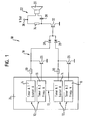
- This tone generator 10 has at least one electronic tone signal source 12 i , which in each case comprises a module 14 which supplies the tone frequency and a module 16 which specifies the tone volume.
- the respective electronic sound signal source 12 i is connected to a driver circuit 22 assigned to a loudspeaker 20 via a circuit 18 combining the output signals of its two modules 14, 16.
- the modules 14, 16 are preferably formed by a microcontroller 24, which is particularly a standard microcontroller can act.
- the modules 14, 16 can in particular each have one Include timers.
- a respective module 16 providing the audio frequency can be formed, for example, by a multivibrator with a timer.
- the relevant timers or multivibrators can again by appropriate Modules of the microcontroller 24 can be formed.
- the sound volume is based, for example, on pulse width modulation (PWM) adjustable.
- PWM pulse width modulation
- Circuit 18 can in particular be a simple one Act transistor / diode circuit.
- the circuit 18 combining the output signals of the two modules 14, 16 of a respective audio signal source 12 i can comprise, for example, a transistor 26, the supply voltage of which is supplied via the module 14 that specifies the volume and can be varied accordingly and the module 16 that supplies the audio frequency is controllable.
- the exit is the Output signals of the two respective modules 14, 16 combining with each other Circuit 18 via a diode 28 with driver circuit 22 connected.
- the circuits 18 are each by an emitter circuit formed with a bipolar npn transistor 26 whose emitter lies on ground, the base of which with the respective module 16 and its Collector on the one hand via a resistor 30 with the module 14 and on the other hand is connected to the diode 28.
- One or more electronic audio signal sources 12 i can be provided. In the embodiment shown in FIG. 1, n such electronic sound signal sources 12 1 - 12 n are provided.
- the various modules 14, 16 of these electronic sound signal sources 12 i can be formed by a single microcontroller 24.
- the outputs of the output signals of the respective module pairs 14, 16 circuits 18 which combine with one another are in the present case connected to a single input of the driver circuit 22.
- the driver circuit 22 is through only one transistor stage is formed. This can be, as in the present Case, for example, an emitter circuit. It is for example, a bipolar npn transistor 32 is again provided Emitter lies on ground. The base of this transistor 32 forms the input the driver circuit 22 with which the outputs of the circuits 18 are connected. The collector of transistor 32 is connected across a collector resistor 34 at the positive terminal 36 of a supply voltage, for example a battery. The speaker 20 is over one Capacitor 38 connected in parallel to the collector resistor 34.
- the driver or amplifier circuit 22 can thus be controlled via one or more electronic audio signal sources 12 i .
Landscapes
- Physics & Mathematics (AREA)
- Engineering & Computer Science (AREA)
- Acoustics & Sound (AREA)
- Multimedia (AREA)
- Circuit For Audible Band Transducer (AREA)
- Amplifiers (AREA)
Abstract
Description
- 10
- Tongenerator
- 12i
- Tonsignalquelle
- 14
- Tonfrequenz liefernder Modul
- 16
- Lautstärke vorgebender Modul
- 18
- die Ausgangssignale der Module miteinander kombinierende Schaltung
- 20
- Lautsprecher
- 22
- Treiberschaltung
- 24
- Mikrocontroller
- 26
- Transistor
- 28
- Diode
- 30
- Widerstand
- 32
- Transistor
- 34
- Widerstand
- 36
- positive Klemme einer Versorgungsspannung
- 38
- Kondensator
Claims (14)
- Tongenerator (10) mit wenigstens einer elektronischen Tonsignalquelle (12i), die einen die Tonfrequenz liefernden Modul (14) und einen die Tonlautstärke vorgebenden Modul (14) umfaßt und über eine die Ausgangssignale dieser beiden Module (14, 16) miteinander kombinierende Schaltung (18) mit einer einem Lautsprecher (20) zugeordneten Treiberschaltung (22) verbunden ist.
- Tongenerator nach Anspruch 1,
dadurch gekennzeichnet, daß die beiden Module (14, 16) durch einen Mikrocontroller (24) oder durch integrierte Peripheriebausteine eines solchen Mikrocontrollers (24) gebildet sind. - Tongenerator nach Anspruch 1 oder 2,
dadurch gekennzeichnet, daß die beiden Module (14, 16) jeweils einen Timer umfassen. - Tongenerator nach einem der vorhergehenden Ansprüche,
dadurch gekennzeichnet, daß der die Tonfrequenz liefernde Modul (16) durch einen Multivibrator mit Timer gebildet ist. - Tongenerator nach Anspruch 3 oder 4,
dadurch gekennzeichnet, daß die Timer (14, 16) durch entsprechende Module eines Mikrocontrollers (24) gebildet sind. - Tongenerator nach einem der vorhergehenden Ansprüche,
dadurch gekennzeichnet, daß die Tonlautstärke auf der Basis einer Pulsbreiten-Modulation einstellbar ist. - Tongenerator nach einem der vorhergehenden Ansprüche,
dadurch gekennzeichnet, daß die die Ausgangssignale der beiden Module (14, 16) miteinander kombinierende Schaltung (18) eine Transistor/Dioden-Schaltung ist. - Tongenerator nach einem der vorhergehenden Ansprüche,
dadurch gekennzeichnet, daß die die Ausgangssignale der beiden Module (14, 16) miteinander kombinierende Schaltung einen Transistor (26) umfaßt, dessen Versorgungsspannung über den die Tonlautstärke vorgebenden Modul geliefert wird und entsprechend variierbar ist und der über den die Tonfrequenz liefernden Modul (16) ansteuerbar ist. - Tongenerator nach einem der vorhergehenden Ansprüche,
dadurch gekennzeichnet, daß der Ausgang der die Ausgangssignale der beiden Module miteinander kombinierenden Schaltung (18) über eine Diode (28) mit der Treiberschaltung (22) verbunden ist. - Tongenerator nach einem der vorhergehenden Ansprüche,
dadurch gekennzeichnet, daß die die Ausgangssignale der beiden Module (14, 16) miteinander kombinierende Schaltung (18) eine Emitterschaltung umfaßt. - Tongenerator nach einem der vorhergehenden Ansprüche,
dadurch gekennzeichnet, daß mehrere elektronische Tonsignalquellen (12i) vorgesehen sind, deren Module vorzugsweise durch einen einzigen Mikrocontroller (24) gebildet sind. - Tongenerator nach Anspruch 11,
dadurch gekennzeichnet, daß die Ausgänge der die Ausgangssignale der jeweiligen Modulpaare (14, 16) miteinander kombinierenden Schaltungen (18) mit vorzugsweise einem einzigen Eingang der Treiberschaltung (22) verbunden sind. - Tongenerator nach einem der vorhergehenden Ansprüche,
dadurch gekennzeichnet, daß die Treiberschaltung (22) durch nur eine Transistorstufe gebildet ist. - Tongenerator nach einem der vorhergehenden Ansprüche,
dadurch gekennzeichnet, daß die Treiberschaltung (22) eine Emitterschaltung umfaßt.
Applications Claiming Priority (2)
| Application Number | Priority Date | Filing Date | Title |
|---|---|---|---|
| DE10137529 | 2001-08-01 | ||
| DE2001137529 DE10137529A1 (de) | 2001-08-01 | 2001-08-01 | Tongenerator |
Publications (3)
| Publication Number | Publication Date |
|---|---|
| EP1288909A2 true EP1288909A2 (de) | 2003-03-05 |
| EP1288909A3 EP1288909A3 (de) | 2003-03-12 |
| EP1288909B1 EP1288909B1 (de) | 2007-10-31 |
Family
ID=7693885
Family Applications (1)
| Application Number | Title | Priority Date | Filing Date |
|---|---|---|---|
| EP20020016291 Expired - Lifetime EP1288909B1 (de) | 2001-08-01 | 2002-07-23 | Tongenerator |
Country Status (2)
| Country | Link |
|---|---|
| EP (1) | EP1288909B1 (de) |
| DE (2) | DE10137529A1 (de) |
Family Cites Families (5)
| Publication number | Priority date | Publication date | Assignee | Title |
|---|---|---|---|---|
| US4186642A (en) * | 1977-09-22 | 1980-02-05 | Norlin Industries, Inc. | Programmable circuits for electronic musical instruments |
| JPS5946691A (ja) * | 1982-09-09 | 1984-03-16 | セイコーエプソン株式会社 | 音響発生回路 |
| US5014587A (en) * | 1989-10-16 | 1991-05-14 | The Quaker Oats Company | Electronic piano tone circuit |
| DE4103897A1 (de) * | 1991-02-08 | 1991-09-19 | Siemens Ag | Integrierbare tongeberschaltungsanordnung |
| DE19860113B4 (de) * | 1998-12-23 | 2004-03-18 | Siemens Ag | Verfahren und Vorrichtung zum Erzeugen von Geräuschen, insbesondere von Schaltgeräuschen |
-
2001
- 2001-08-01 DE DE2001137529 patent/DE10137529A1/de not_active Withdrawn
-
2002
- 2002-07-23 DE DE50211129T patent/DE50211129D1/de not_active Expired - Fee Related
- 2002-07-23 EP EP20020016291 patent/EP1288909B1/de not_active Expired - Lifetime
Also Published As
| Publication number | Publication date |
|---|---|
| DE10137529A1 (de) | 2003-02-13 |
| EP1288909B1 (de) | 2007-10-31 |
| DE50211129D1 (de) | 2007-12-13 |
| EP1288909A3 (de) | 2003-03-12 |
Similar Documents
| Publication | Publication Date | Title |
|---|---|---|
| DE69426650T2 (de) | Mischer für Sender, mit einem Eingang im Strom-Modus | |
| DE68924394T2 (de) | Vorrichtung zum Erzeugen einer Referenzspannung für einen eine kapazitive Bootstrapschaltung enthaltenden Schalter. | |
| DE69814309T2 (de) | Niederspannungsverstärker | |
| DE69026468T2 (de) | Anpassungsfähige Gate-Entladeschaltung für Leistungs-Fets | |
| DE19982963B4 (de) | Dynamische Vorspannungsschaltung, die eine frühe Spannungsklemmschaltung und translineare Techniken benutzt | |
| EP0570820B1 (de) | Schaltbare Stromquellenschaltung und Verwendung einer solchen in einer Phasendetektoranordnung | |
| EP0011704B1 (de) | Referenzspannungsquelle, insbesondere für Verstärkerschaltungen | |
| EP1288909B1 (de) | Tongenerator | |
| DE2627339C2 (de) | Bipolar-monolithisch integrierte Gegentakt-Endstufe für Digitalsignale | |
| DE2203872A1 (de) | Niederfrequenz-Leistungsverstärker | |
| DE102004022991B3 (de) | Abtast-Differenzverstärker und Abtast-Verstärker | |
| DE3603799A1 (de) | Stromspiegelschaltung | |
| DE3006453C2 (de) | Tonsignalsteuerschaltung für ein elektronisches Musikinstrument | |
| DE10202336A1 (de) | Transmitterendstufe für einen Zweidrahtbus | |
| DE3409417C2 (de) | Niederfrequenz-Verstärker | |
| EP0766163B1 (de) | Schaltungsanordnung zur Erzeugung eines Biaspotentials | |
| DE4239140C1 (de) | Integrierbare Schaltungsanordnung zum Abgleich eines Steuersignals | |
| EP0052236B1 (de) | Tongenerator | |
| DE19960236A1 (de) | Aufwärts-Leistungsversorgungsschaltung und integrierte Halbleiterschaltungsvorrichtung | |
| DE2924927B2 (de) | Elektronische Uhr mit Schrittschaltmotor, versehen mit einer Alarmeinrichtung | |
| DE3633415C2 (de) | ||
| DE3149571C3 (de) | Funksendegerät mit einer durch einen Impulsgeber gesteuerten elektronischen Tastschaltung | |
| DE2907597A1 (de) | Ausgangsschaltung fuer ein in der technik mit integrierter injektion aufgebautes digitales verknuepfungsglied | |
| DE3801530A1 (de) | Bicmos-treiberschaltung | |
| DE3787376T2 (de) | Tonfrequenzverstärker. |
Legal Events
| Date | Code | Title | Description |
|---|---|---|---|
| PUAI | Public reference made under article 153(3) epc to a published international application that has entered the european phase |
Free format text: ORIGINAL CODE: 0009012 |
|
| PUAL | Search report despatched |
Free format text: ORIGINAL CODE: 0009013 |
|
| AK | Designated contracting states |
Designated state(s): AT BE BG CH CY CZ DE DK EE ES FI FR GB GR IE IT LI LU MC NL PT SE SK TR Kind code of ref document: A2 Designated state(s): AT BE BG CH CY CZ DE DK EE ES FI FR GB GR IE IT LI LU MC NL PT SE SK TR |
|
| AX | Request for extension of the european patent |
Extension state: AL LT LV MK RO SI |
|
| AK | Designated contracting states |
Kind code of ref document: A3 Designated state(s): AT BE BG CH CY CZ DE DK EE ES FI FR GB GR IE IT LI LU MC NL PT SE SK TR |
|
| AX | Request for extension of the european patent |
Extension state: AL LT LV MK RO SI |
|
| AKX | Designation fees paid | ||
| 17P | Request for examination filed |
Effective date: 20030414 |
|
| RBV | Designated contracting states (corrected) |
Designated state(s): DE FR GB IT SE |
|
| REG | Reference to a national code |
Ref country code: DE Ref legal event code: 8566 |
|
| 17Q | First examination report despatched |
Effective date: 20061005 |
|
| GRAP | Despatch of communication of intention to grant a patent |
Free format text: ORIGINAL CODE: EPIDOSNIGR1 |
|
| GRAS | Grant fee paid |
Free format text: ORIGINAL CODE: EPIDOSNIGR3 |
|
| GRAA | (expected) grant |
Free format text: ORIGINAL CODE: 0009210 |
|
| AK | Designated contracting states |
Kind code of ref document: B1 Designated state(s): DE FR GB IT SE |
|
| REG | Reference to a national code |
Ref country code: GB Ref legal event code: FG4D Free format text: NOT ENGLISH |
|
| REF | Corresponds to: |
Ref document number: 50211129 Country of ref document: DE Date of ref document: 20071213 Kind code of ref document: P |
|
| PG25 | Lapsed in a contracting state [announced via postgrant information from national office to epo] |
Ref country code: SE Free format text: LAPSE BECAUSE OF FAILURE TO SUBMIT A TRANSLATION OF THE DESCRIPTION OR TO PAY THE FEE WITHIN THE PRESCRIBED TIME-LIMIT Effective date: 20080131 |
|
| GBV | Gb: ep patent (uk) treated as always having been void in accordance with gb section 77(7)/1977 [no translation filed] | ||
| ET | Fr: translation filed | ||
| PLBE | No opposition filed within time limit |
Free format text: ORIGINAL CODE: 0009261 |
|
| STAA | Information on the status of an ep patent application or granted ep patent |
Free format text: STATUS: NO OPPOSITION FILED WITHIN TIME LIMIT |
|
| 26N | No opposition filed |
Effective date: 20080801 |
|
| PGFP | Annual fee paid to national office [announced via postgrant information from national office to epo] |
Ref country code: DE Payment date: 20080807 Year of fee payment: 7 |
|
| PG25 | Lapsed in a contracting state [announced via postgrant information from national office to epo] |
Ref country code: GB Free format text: LAPSE BECAUSE OF FAILURE TO SUBMIT A TRANSLATION OF THE DESCRIPTION OR TO PAY THE FEE WITHIN THE PRESCRIBED TIME-LIMIT Effective date: 20071031 |
|
| PGFP | Annual fee paid to national office [announced via postgrant information from national office to epo] |
Ref country code: FR Payment date: 20080718 Year of fee payment: 7 Ref country code: IT Payment date: 20080728 Year of fee payment: 7 |
|
| REG | Reference to a national code |
Ref country code: FR Ref legal event code: ST Effective date: 20100331 |
|
| PG25 | Lapsed in a contracting state [announced via postgrant information from national office to epo] |
Ref country code: FR Free format text: LAPSE BECAUSE OF NON-PAYMENT OF DUE FEES Effective date: 20090731 |
|
| PG25 | Lapsed in a contracting state [announced via postgrant information from national office to epo] |
Ref country code: DE Free format text: LAPSE BECAUSE OF NON-PAYMENT OF DUE FEES Effective date: 20100202 |
|
| PG25 | Lapsed in a contracting state [announced via postgrant information from national office to epo] |
Ref country code: IT Free format text: LAPSE BECAUSE OF NON-PAYMENT OF DUE FEES Effective date: 20090723 |