EP1286422A1 - Baugruppe bestehend aus Schneidklemmkontakten und Aufpresshülsen - Google Patents
Baugruppe bestehend aus Schneidklemmkontakten und Aufpresshülsen Download PDFInfo
- Publication number
- EP1286422A1 EP1286422A1 EP02016341A EP02016341A EP1286422A1 EP 1286422 A1 EP1286422 A1 EP 1286422A1 EP 02016341 A EP02016341 A EP 02016341A EP 02016341 A EP02016341 A EP 02016341A EP 1286422 A1 EP1286422 A1 EP 1286422A1
- Authority
- EP
- European Patent Office
- Prior art keywords
- contact
- insulation displacement
- section
- housing
- connection
- Prior art date
- Legal status (The legal status is an assumption and is not a legal conclusion. Google has not performed a legal analysis and makes no representation as to the accuracy of the status listed.)
- Granted
Links
- 238000006073 displacement reaction Methods 0.000 title claims abstract description 46
- 238000002788 crimping Methods 0.000 title description 2
- 238000009413 insulation Methods 0.000 claims abstract description 48
- 238000003825 pressing Methods 0.000 claims description 3
- 229910000679 solder Inorganic materials 0.000 claims description 2
- 238000004873 anchoring Methods 0.000 description 3
- 239000002184 metal Substances 0.000 description 2
- 238000005476 soldering Methods 0.000 description 2
- 239000000969 carrier Substances 0.000 description 1
- 238000005266 casting Methods 0.000 description 1
- 230000000052 comparative effect Effects 0.000 description 1
- 238000001035 drying Methods 0.000 description 1
- 238000000034 method Methods 0.000 description 1
- 238000004382 potting Methods 0.000 description 1
Images


Classifications
-
- H—ELECTRICITY
- H01—ELECTRIC ELEMENTS
- H01R—ELECTRICALLY-CONDUCTIVE CONNECTIONS; STRUCTURAL ASSOCIATIONS OF A PLURALITY OF MUTUALLY-INSULATED ELECTRICAL CONNECTING ELEMENTS; COUPLING DEVICES; CURRENT COLLECTORS
- H01R9/00—Structural associations of a plurality of mutually-insulated electrical connecting elements, e.g. terminal strips or terminal blocks; Terminals or binding posts mounted upon a base or in a case; Bases therefor
- H01R9/03—Connectors arranged to contact a plurality of the conductors of a multiconductor cable, e.g. tapping connections
- H01R9/031—Connectors arranged to contact a plurality of the conductors of a multiconductor cable, e.g. tapping connections for multiphase cables, e.g. with contact members penetrating insulation of a plurality of conductors
-
- H—ELECTRICITY
- H01—ELECTRIC ELEMENTS
- H01R—ELECTRICALLY-CONDUCTIVE CONNECTIONS; STRUCTURAL ASSOCIATIONS OF A PLURALITY OF MUTUALLY-INSULATED ELECTRICAL CONNECTING ELEMENTS; COUPLING DEVICES; CURRENT COLLECTORS
- H01R13/00—Details of coupling devices of the kinds covered by groups H01R12/70 or H01R24/00 - H01R33/00
- H01R13/62—Means for facilitating engagement or disengagement of coupling parts or for holding them in engagement
- H01R13/627—Snap or like fastening
- H01R13/6277—Snap or like fastening comprising annular latching means, e.g. ring snapping in an annular groove
-
- H—ELECTRICITY
- H01—ELECTRIC ELEMENTS
- H01R—ELECTRICALLY-CONDUCTIVE CONNECTIONS; STRUCTURAL ASSOCIATIONS OF A PLURALITY OF MUTUALLY-INSULATED ELECTRICAL CONNECTING ELEMENTS; COUPLING DEVICES; CURRENT COLLECTORS
- H01R4/00—Electrically-conductive connections between two or more conductive members in direct contact, i.e. touching one another; Means for effecting or maintaining such contact; Electrically-conductive connections having two or more spaced connecting locations for conductors and using contact members penetrating insulation
- H01R4/10—Electrically-conductive connections between two or more conductive members in direct contact, i.e. touching one another; Means for effecting or maintaining such contact; Electrically-conductive connections having two or more spaced connecting locations for conductors and using contact members penetrating insulation effected solely by twisting, wrapping, bending, crimping, or other permanent deformation
- H01R4/18—Electrically-conductive connections between two or more conductive members in direct contact, i.e. touching one another; Means for effecting or maintaining such contact; Electrically-conductive connections having two or more spaced connecting locations for conductors and using contact members penetrating insulation effected solely by twisting, wrapping, bending, crimping, or other permanent deformation by crimping
- H01R4/183—Electrically-conductive connections between two or more conductive members in direct contact, i.e. touching one another; Means for effecting or maintaining such contact; Electrically-conductive connections having two or more spaced connecting locations for conductors and using contact members penetrating insulation effected solely by twisting, wrapping, bending, crimping, or other permanent deformation by crimping for cylindrical elongated bodies, e.g. cables having circular cross-section
Definitions
- the housing which can be a turned part made of metal, is usually with a Provide contact carrier, which is equipped with several insulation displacement contacts is.
- the insulation displacement contacts are designed as insulation displacement terminals at one end and at the other end as a contact section. Can in the insulation displacement clamps a cable to be connected is pressed in such a way that its insulation is cut and the inner wires are contacted. With the contact section a cable is usually soldered.
- the housing together with the Contact carriers are usually cast.
- the object of the invention is that with the insulation displacement contacts to further equip equipped housings in such a way that a shorter assembly time is achieved with simplified handling.
- an assembly which consists of an insulating housing in which at least one insulation displacement contact is arranged, which has an insulation displacement terminal and a contact section, and from a holding element which has at least one connection contact, wherein the connection contact has a press-on section, which on the Contact section of the insulation displacement contact is pressed, and a connecting section, the one to be connected to the insulation displacement contact Cable can be connected.
- an insulation displacement element is provided for each insulation displacement contact, namely the connection contact, which is pressed onto the contact section of the insulation displacement contact is and therefore makes the previously required soldering process superfluous.
- Insulation displacement contact cables to be connected can either in the connection sleeve be soldered in, or the connecting sleeve can be crimped onto the cable. Pre-assembled components can also be produced in this way. It is then only for connecting the cables to the insulation displacement contacts required to snap the retaining element into the housing.
- the assembly includes a housing 10, one on the outside Locking groove 11 is formed. The function of the locking groove will be explained later.
- a contact carrier 12 is arranged, in which four insulation displacement contacts 14 are used. 1 of the insulation displacement contacts to 3 see essentially only one contact section 16, here as a contact pin is executed.
- each insulation displacement contact is designed as an insulation displacement terminal. In the Insulation displacement terminal, a cable to be connected can be pressed in, the Insulation clamp cuts through the insulation of the cable and contacts its wire.
- the housing can be used as a wall bushing.
- At least the holding element 20 and the contact carrier 12 consist of electrical insulating plastic.
- the housing 10 can, depending on the application also consist of plastic or metal.
- a lock nut 30 can be placed on the holding element 20 be attached to the housing 10.
- a pressure screw 32 can be screwed on by means of the housing Pressure part is pressed onto the insulation displacement clamps in the way that is guided in the pressure part Cables are pressed into the insulation displacement contacts of the insulation displacement contacts. This is known from the prior art, so that it is not further described here becomes.
- the locking collar 21 of the holding element 20 is like this executed that it can be inserted into the interior of the housing 10. there snaps a collar 36 on the locking collar 21 in the formed in the housing 10 Locking groove 11 a. The holding element 20 is then firmly accommodated in the housing 10.
Landscapes
- Multi-Conductor Connections (AREA)
- Details Of Connecting Devices For Male And Female Coupling (AREA)
- Connections By Means Of Piercing Elements, Nuts, Or Screws (AREA)
- Coupling Device And Connection With Printed Circuit (AREA)
Abstract
Description
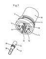
- Figur 1 in einer perspektivischen Ansicht ein Gehäuse mit Schneidklemmkontakten sowie einen Anschlußkontakt gemäß einer ersten Ausführungsform;
- Figur 2 die Bauteile von Figur 1, wobei der Anschlußkontakt auf den Kontaktabschnitt des Schneidklemmkontaktes aufgeschoben ist;
- Figur 3 ein Gehäuse mit Schneidklemmkontakten sowie ein Halteelement mit Anschlußkontakten;
- Figur 4 das Gehäuse mit aufgesetztem Halteelement und zusätzlicher Kontermutter;
- Figur 5 eine perspektivische Ansicht einer Baugruppe gemäß einer zweiten Ausführungsform der Erfindung;
- Figur 6 eine weitere perspektivische Ansicht der Baugruppe von Figur 5;
- Figur 7 eine weitere perspektivische Ansicht der Baugruppe von Figur 6 mit angeschlossenen Kabeln;
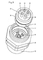
- Figur 8 eine perspektivische Ansicht des Gehäuses von Figur 5 mit separat dargestellten Anschlußkontakten; und
- Figur 9 eine Ansicht entsprechend derjenigen von Figur 8, wobei die Anschlußkontakte eingesetzt in ein Halteelement gezeigt sind.
- 10:
- Gehäuse
- 11:
- Rastnut
- 12:
- Kontaktträger
- 14:
- Schneidklemmkontakt
- 16:
- Kontaktabschnitt
- 18:
- Schneidklemme
- 20:
- Halteelement
- 21:
- Rastkragen
- 22:
- Anschlußkontakt
- 24:
- Aufpreßabschnitt
- 26:
- Verankerungsabschnitt
- 28:
- Anschlußabschnitt
- 30:
- Kontermutter
- 32:
- Druckschraube
- 34:
- Kabel
- 36:
- Bund
Claims (9)
- Baugruppe bestehend aus einem isolierenden Gehäuse (10), in dem mindedestens ein Schneidklemmkontakt (14) angeordnet ist, der eine Schneidklemme (18) und einen Kontaktabschnitt (16) aufweist, und aus einem Halteelement (20), das mindestens einen Anschlußkontakt (22) aufweist, wobei der Anschlußkontakt einen Aufpreßabschnitt (24) aufweist, der auf den Kontaktabschnitt (16) des Schneidklemmkontaktes aufgepreßt ist, und einen Anschlußabschnitt (28), der mit einem an den Schneidklemmkontakt anzuschließenden Kabel verbunden werden kann.
- Baugruppe nach Anspruch 1, dadurch gekennzeichnet, daß der Kontaktabschnitt (16) des Schneidklemmkontakts (14) als Kontaktstift ausgeführt ist.
- Baugruppe nach Anspruch 1 oder 2, dadurch gekennzeichnet, daß der Aufpreßabschnitt (24) des Anschlußkontaktes (22) eine Aufpreßhülse ist.
- Baugruppe nach einem der vorhergehenden Ansprüche, dadurch gekennzeichnet, daß der Anschlußabschnitt (28) des Anschlußkontaktes (22) als Lötanschluß ausgeführt ist.
- Baugruppe nach Anspruch 4, dadurch gekennzeichnet, daß in die Anschlußhülse ein Kabel (34) eingelötet ist.
- Baugruppe nach einem der Ansprüche 1 bis 3, dadurch gekennzeichnet, daß der Anschlußabschnitt (28) des Anschlußkontaktes (22) eine Crimphülse ist.
- Baugruppe nach einem der vorhergehenden Ansprüche, dadurch gekennzeichnet, daß das Halteelement (20) fest am Gehäuse (10) verrastet ist.
- Baugruppe nach Anspruch 7, dadurch gekennzeichnet, daß das Halteelement (20) einen Rastkragen (21) aufweist.
- Baugruppe nach Anspruch 8, dadurch gekennzeichnet, daß das Gehäuse (10) eine Rastnut (11) aufweist, in die der Rastkragen (21) eingreift.
Applications Claiming Priority (2)
| Application Number | Priority Date | Filing Date | Title |
|---|---|---|---|
| DE10140023 | 2001-08-16 | ||
| DE10140023A DE10140023A1 (de) | 2001-08-16 | 2001-08-16 | Baugruppe bestehend aus Schneidklemmkontakten und Aufpreßhülsen |
Publications (2)
| Publication Number | Publication Date |
|---|---|
| EP1286422A1 true EP1286422A1 (de) | 2003-02-26 |
| EP1286422B1 EP1286422B1 (de) | 2004-09-29 |
Family
ID=7695502
Family Applications (1)
| Application Number | Title | Priority Date | Filing Date |
|---|---|---|---|
| EP02016341A Expired - Lifetime EP1286422B1 (de) | 2001-08-16 | 2002-07-25 | Baugruppe bestehend aus Schneidklemmkontakten und Aufpresshülsen |
Country Status (4)
| Country | Link |
|---|---|
| EP (1) | EP1286422B1 (de) |
| AT (1) | ATE278255T1 (de) |
| DE (2) | DE10140023A1 (de) |
| ES (1) | ES2230428T3 (de) |
Cited By (1)
| Publication number | Priority date | Publication date | Assignee | Title |
|---|---|---|---|---|
| DE102011103327A1 (de) * | 2011-05-27 | 2012-11-29 | Mc Technology Gmbh | Kontaktstift für Steckverbinder |
Families Citing this family (1)
| Publication number | Priority date | Publication date | Assignee | Title |
|---|---|---|---|---|
| DE102004058945B4 (de) * | 2004-12-08 | 2009-11-26 | Semikron Elektronik Gmbh & Co. Kg | Steckverbinder zur dauerhaft sicheren elektrisch Verbindung |
Citations (5)
| Publication number | Priority date | Publication date | Assignee | Title |
|---|---|---|---|---|
| DE3237093A1 (de) * | 1982-10-07 | 1984-04-12 | Dr.Ing.H.C. F. Porsche Ag, 7000 Stuttgart | Elektrische steckvorrichtung |
| DE29915553U1 (de) * | 1999-09-03 | 1999-11-25 | HARTING KGaA, 32339 Espelkamp | Steckverbinder |
| DE20005868U1 (de) * | 2000-03-30 | 2000-06-21 | HARTING KGaA, 32339 Espelkamp | Elektrischer Verbinder |
| DE20005870U1 (de) * | 2000-03-30 | 2000-06-21 | HARTING KGaA, 32339 Espelkamp | Elektrischer Anschluss |
| US6120316A (en) * | 1996-04-13 | 2000-09-19 | Richard Hirschmann Gmbh & Co. | Cable plug connector |
Family Cites Families (2)
| Publication number | Priority date | Publication date | Assignee | Title |
|---|---|---|---|---|
| DE2935508C2 (de) * | 1979-09-03 | 1987-02-05 | Telefonbau Und Normalzeit Gmbh, 6000 Frankfurt | Anschluß von Litzendrähten an Schneidsteckverbindern bei elektrischen-insbesondere fernmeldetechnischen Geräten |
| DE10022374A1 (de) * | 2000-05-08 | 2001-11-15 | Harting Kgaa | Steckverbinder und Verfahren zur Montage eines Steckverbinders |
-
2001
- 2001-08-16 DE DE10140023A patent/DE10140023A1/de not_active Withdrawn
-
2002
- 2002-07-25 EP EP02016341A patent/EP1286422B1/de not_active Expired - Lifetime
- 2002-07-25 AT AT02016341T patent/ATE278255T1/de not_active IP Right Cessation
- 2002-07-25 ES ES02016341T patent/ES2230428T3/es not_active Expired - Lifetime
- 2002-07-25 DE DE50201147T patent/DE50201147D1/de not_active Expired - Fee Related
Patent Citations (5)
| Publication number | Priority date | Publication date | Assignee | Title |
|---|---|---|---|---|
| DE3237093A1 (de) * | 1982-10-07 | 1984-04-12 | Dr.Ing.H.C. F. Porsche Ag, 7000 Stuttgart | Elektrische steckvorrichtung |
| US6120316A (en) * | 1996-04-13 | 2000-09-19 | Richard Hirschmann Gmbh & Co. | Cable plug connector |
| DE29915553U1 (de) * | 1999-09-03 | 1999-11-25 | HARTING KGaA, 32339 Espelkamp | Steckverbinder |
| DE20005868U1 (de) * | 2000-03-30 | 2000-06-21 | HARTING KGaA, 32339 Espelkamp | Elektrischer Verbinder |
| DE20005870U1 (de) * | 2000-03-30 | 2000-06-21 | HARTING KGaA, 32339 Espelkamp | Elektrischer Anschluss |
Cited By (1)
| Publication number | Priority date | Publication date | Assignee | Title |
|---|---|---|---|---|
| DE102011103327A1 (de) * | 2011-05-27 | 2012-11-29 | Mc Technology Gmbh | Kontaktstift für Steckverbinder |
Also Published As
| Publication number | Publication date |
|---|---|
| EP1286422B1 (de) | 2004-09-29 |
| DE50201147D1 (de) | 2004-11-04 |
| ES2230428T3 (es) | 2005-05-01 |
| DE10140023A1 (de) | 2003-02-27 |
| ATE278255T1 (de) | 2004-10-15 |
Similar Documents
| Publication | Publication Date | Title |
|---|---|---|
| EP2442403B1 (de) | Schraubenlose Anschlussklemme | |
| EP2301115B1 (de) | Elektrische anschlussvorrichtung | |
| DE19951455C1 (de) | Kabelanschluss- oder -verbindungseinrichtung | |
| DE29915553U1 (de) | Steckverbinder | |
| DE69013582T2 (de) | Keilförmiger Sockel, befestigt an SPG-Substrat. | |
| EP2118969B1 (de) | Steckersystem | |
| DE2413174B2 (de) | Elektrischer Verbinder | |
| DE3437829C1 (de) | Elektrischer Verbinder,insbesondere fuer Fernmeldeverteiler | |
| DE102007055040B4 (de) | Kontaktelement und Verfahren zur Herstellung eines Kontaktelementes | |
| EP3698438B1 (de) | Vorrichtung zur elektrischen kontaktierung | |
| DE3135173C2 (de) | Als elektrischer Stecker oder als Steckdose oder als Kupplungsdose ausgebildetes Installationsteil | |
| EP1870961A1 (de) | Kabelverbindung | |
| DE2550245A1 (de) | Anschlussklemme fuer eine vorrichtung oder ein element zur elektrischen verbindung | |
| DE3942276C2 (de) | ||
| DE69015378T2 (de) | Verbindungseinrichtung für Koaxialkabel und entsprechender Verbindungsmodul, insbesondere Verbindungsblock. | |
| EP3782235B1 (de) | Direktsteckverbinder | |
| DE7837478U1 (de) | AnschluBteU für elektrische Leitungen | |
| DE29806869U1 (de) | Elektrisches Anschlußelement | |
| EP3539183B1 (de) | Kontaktelement mit einem klemmenden anschluss für litzenleiter | |
| EP3168933B1 (de) | Steckdosenpolkontakt | |
| EP0319633B1 (de) | Cinch-Stecker | |
| DE19528235C2 (de) | Vorrichtung zur Verbindung der Abschirmung eines Kabels mit dem Gehäuse eines elektrischen Verbinders | |
| EP1286422B1 (de) | Baugruppe bestehend aus Schneidklemmkontakten und Aufpresshülsen | |
| DE69326458T2 (de) | Verbindervorrichtung für elektrische Bauteile | |
| DE10323616A1 (de) | Schnellanschließbare Steckverbindung in Spannzangentechnik |
Legal Events
| Date | Code | Title | Description |
|---|---|---|---|
| PUAI | Public reference made under article 153(3) epc to a published international application that has entered the european phase |
Free format text: ORIGINAL CODE: 0009012 |
|
| AK | Designated contracting states |
Kind code of ref document: A1 Designated state(s): AT BE BG CH CY CZ DE DK EE ES FI FR GB GR IE IT LI LU MC NL PT SE SK TR |
|
| AX | Request for extension of the european patent |
Extension state: AL LT LV MK RO SI |
|
| 17P | Request for examination filed |
Effective date: 20030613 |
|
| 17Q | First examination report despatched |
Effective date: 20030919 |
|
| AKX | Designation fees paid |
Designated state(s): AT BE BG CH CY CZ DE DK EE ES FI FR GB GR IE IT LI LU MC NL PT SE SK TR |
|
| RAP1 | Party data changed (applicant data changed or rights of an application transferred) |
Owner name: HARTING ELECTRIC GMBH & CO. KG |
|
| GRAP | Despatch of communication of intention to grant a patent |
Free format text: ORIGINAL CODE: EPIDOSNIGR1 |
|
| GRAS | Grant fee paid |
Free format text: ORIGINAL CODE: EPIDOSNIGR3 |
|
| GRAA | (expected) grant |
Free format text: ORIGINAL CODE: 0009210 |
|
| AK | Designated contracting states |
Kind code of ref document: B1 Designated state(s): AT BE BG CH CY CZ DE DK EE ES FI FR GB GR IE IT LI LU MC NL PT SE SK TR |
|
| PG25 | Lapsed in a contracting state [announced via postgrant information from national office to epo] |
Ref country code: NL Free format text: LAPSE BECAUSE OF FAILURE TO SUBMIT A TRANSLATION OF THE DESCRIPTION OR TO PAY THE FEE WITHIN THE PRESCRIBED TIME-LIMIT Effective date: 20040929 Ref country code: SK Free format text: LAPSE BECAUSE OF FAILURE TO SUBMIT A TRANSLATION OF THE DESCRIPTION OR TO PAY THE FEE WITHIN THE PRESCRIBED TIME-LIMIT Effective date: 20040929 Ref country code: IE Free format text: LAPSE BECAUSE OF FAILURE TO SUBMIT A TRANSLATION OF THE DESCRIPTION OR TO PAY THE FEE WITHIN THE PRESCRIBED TIME-LIMIT Effective date: 20040929 Ref country code: EE Free format text: LAPSE BECAUSE OF FAILURE TO SUBMIT A TRANSLATION OF THE DESCRIPTION OR TO PAY THE FEE WITHIN THE PRESCRIBED TIME-LIMIT Effective date: 20040929 Ref country code: FI Free format text: LAPSE BECAUSE OF FAILURE TO SUBMIT A TRANSLATION OF THE DESCRIPTION OR TO PAY THE FEE WITHIN THE PRESCRIBED TIME-LIMIT Effective date: 20040929 Ref country code: CZ Free format text: LAPSE BECAUSE OF FAILURE TO SUBMIT A TRANSLATION OF THE DESCRIPTION OR TO PAY THE FEE WITHIN THE PRESCRIBED TIME-LIMIT Effective date: 20040929 Ref country code: TR Free format text: LAPSE BECAUSE OF FAILURE TO SUBMIT A TRANSLATION OF THE DESCRIPTION OR TO PAY THE FEE WITHIN THE PRESCRIBED TIME-LIMIT Effective date: 20040929 Ref country code: BG Free format text: LAPSE BECAUSE OF FAILURE TO SUBMIT A TRANSLATION OF THE DESCRIPTION OR TO PAY THE FEE WITHIN THE PRESCRIBED TIME-LIMIT Effective date: 20040929 |
|
| REG | Reference to a national code |
Ref country code: GB Ref legal event code: FG4D Free format text: NOT ENGLISH |
|
| REG | Reference to a national code |
Ref country code: CH Ref legal event code: EP |
|
| REG | Reference to a national code |
Ref country code: CH Ref legal event code: NV Representative=s name: TROESCH SCHEIDEGGER WERNER AG |
|
| REG | Reference to a national code |
Ref country code: IE Ref legal event code: FG4D Free format text: GERMAN |
|
| REF | Corresponds to: |
Ref document number: 50201147 Country of ref document: DE Date of ref document: 20041104 Kind code of ref document: P |
|
| PG25 | Lapsed in a contracting state [announced via postgrant information from national office to epo] |
Ref country code: DK Free format text: LAPSE BECAUSE OF FAILURE TO SUBMIT A TRANSLATION OF THE DESCRIPTION OR TO PAY THE FEE WITHIN THE PRESCRIBED TIME-LIMIT Effective date: 20041229 Ref country code: GR Free format text: LAPSE BECAUSE OF FAILURE TO SUBMIT A TRANSLATION OF THE DESCRIPTION OR TO PAY THE FEE WITHIN THE PRESCRIBED TIME-LIMIT Effective date: 20041229 Ref country code: SE Free format text: LAPSE BECAUSE OF FAILURE TO SUBMIT A TRANSLATION OF THE DESCRIPTION OR TO PAY THE FEE WITHIN THE PRESCRIBED TIME-LIMIT Effective date: 20041229 |
|
| GBT | Gb: translation of ep patent filed (gb section 77(6)(a)/1977) |
Effective date: 20050117 |
|
| NLV1 | Nl: lapsed or annulled due to failure to fulfill the requirements of art. 29p and 29m of the patents act | ||
| REG | Reference to a national code |
Ref country code: IE Ref legal event code: FD4D |
|
| REG | Reference to a national code |
Ref country code: ES Ref legal event code: FG2A Ref document number: 2230428 Country of ref document: ES Kind code of ref document: T3 |
|
| PG25 | Lapsed in a contracting state [announced via postgrant information from national office to epo] |
Ref country code: CY Free format text: LAPSE BECAUSE OF FAILURE TO SUBMIT A TRANSLATION OF THE DESCRIPTION OR TO PAY THE FEE WITHIN THE PRESCRIBED TIME-LIMIT Effective date: 20050725 Ref country code: LU Free format text: LAPSE BECAUSE OF NON-PAYMENT OF DUE FEES Effective date: 20050725 |
|
| PG25 | Lapsed in a contracting state [announced via postgrant information from national office to epo] |
Ref country code: MC Free format text: LAPSE BECAUSE OF NON-PAYMENT OF DUE FEES Effective date: 20050731 Ref country code: BE Free format text: LAPSE BECAUSE OF NON-PAYMENT OF DUE FEES Effective date: 20050731 |
|
| PLBE | No opposition filed within time limit |
Free format text: ORIGINAL CODE: 0009261 |
|
| STAA | Information on the status of an ep patent application or granted ep patent |
Free format text: STATUS: NO OPPOSITION FILED WITHIN TIME LIMIT |
|
| ET | Fr: translation filed | ||
| 26N | No opposition filed |
Effective date: 20050630 |
|
| BERE | Be: lapsed |
Owner name: *HARTING ELECTRIC G.M.B.H. & CO. K.G. Effective date: 20050731 |
|
| PG25 | Lapsed in a contracting state [announced via postgrant information from national office to epo] |
Ref country code: PT Free format text: LAPSE BECAUSE OF NON-PAYMENT OF DUE FEES Effective date: 20050228 |
|
| PGFP | Annual fee paid to national office [announced via postgrant information from national office to epo] |
Ref country code: ES Payment date: 20090707 Year of fee payment: 8 Ref country code: FR Payment date: 20090722 Year of fee payment: 8 |
|
| PGFP | Annual fee paid to national office [announced via postgrant information from national office to epo] |
Ref country code: AT Payment date: 20090724 Year of fee payment: 8 Ref country code: CH Payment date: 20090728 Year of fee payment: 8 Ref country code: DE Payment date: 20090717 Year of fee payment: 8 Ref country code: GB Payment date: 20090722 Year of fee payment: 8 |
|
| PGFP | Annual fee paid to national office [announced via postgrant information from national office to epo] |
Ref country code: IT Payment date: 20090723 Year of fee payment: 8 |
|
| REG | Reference to a national code |
Ref country code: CH Ref legal event code: PL |
|
| GBPC | Gb: european patent ceased through non-payment of renewal fee |
Effective date: 20100725 |
|
| REG | Reference to a national code |
Ref country code: FR Ref legal event code: ST Effective date: 20110331 |
|
| PG25 | Lapsed in a contracting state [announced via postgrant information from national office to epo] |
Ref country code: CH Free format text: LAPSE BECAUSE OF NON-PAYMENT OF DUE FEES Effective date: 20100731 Ref country code: DE Free format text: LAPSE BECAUSE OF NON-PAYMENT OF DUE FEES Effective date: 20110201 Ref country code: LI Free format text: LAPSE BECAUSE OF NON-PAYMENT OF DUE FEES Effective date: 20100731 |
|
| REG | Reference to a national code |
Ref country code: DE Ref legal event code: R119 Ref document number: 50201147 Country of ref document: DE Effective date: 20110201 |
|
| PG25 | Lapsed in a contracting state [announced via postgrant information from national office to epo] |
Ref country code: AT Free format text: LAPSE BECAUSE OF NON-PAYMENT OF DUE FEES Effective date: 20100725 Ref country code: FR Free format text: LAPSE BECAUSE OF NON-PAYMENT OF DUE FEES Effective date: 20100802 Ref country code: IT Free format text: LAPSE BECAUSE OF NON-PAYMENT OF DUE FEES Effective date: 20100725 |
|
| PG25 | Lapsed in a contracting state [announced via postgrant information from national office to epo] |
Ref country code: GB Free format text: LAPSE BECAUSE OF NON-PAYMENT OF DUE FEES Effective date: 20100725 |
|
| REG | Reference to a national code |
Ref country code: ES Ref legal event code: FD2A Effective date: 20110818 |
|
| PG25 | Lapsed in a contracting state [announced via postgrant information from national office to epo] |
Ref country code: ES Free format text: LAPSE BECAUSE OF NON-PAYMENT OF DUE FEES Effective date: 20100726 |