EP1286014A1 - Fenster oder Fenstertür mit Hilfe der Glasscheibe verriegelt - Google Patents
Fenster oder Fenstertür mit Hilfe der Glasscheibe verriegelt Download PDFInfo
- Publication number
- EP1286014A1 EP1286014A1 EP02014760A EP02014760A EP1286014A1 EP 1286014 A1 EP1286014 A1 EP 1286014A1 EP 02014760 A EP02014760 A EP 02014760A EP 02014760 A EP02014760 A EP 02014760A EP 1286014 A1 EP1286014 A1 EP 1286014A1
- Authority
- EP
- European Patent Office
- Prior art keywords
- window according
- pane
- spars
- bars
- window
- Prior art date
- Legal status (The legal status is an assumption and is not a legal conclusion. Google has not performed a legal analysis and makes no representation as to the accuracy of the status listed.)
- Granted
Links
- 239000011521 glass Substances 0.000 title description 2
- 238000009423 ventilation Methods 0.000 claims description 37
- 238000005096 rolling process Methods 0.000 claims description 7
- 239000002184 metal Substances 0.000 claims description 2
- 230000007246 mechanism Effects 0.000 description 7
- 238000010276 construction Methods 0.000 description 4
- 230000006378 damage Effects 0.000 description 3
- 238000005352 clarification Methods 0.000 description 1
- 238000004140 cleaning Methods 0.000 description 1
- 230000003670 easy-to-clean Effects 0.000 description 1
- 230000000149 penetrating effect Effects 0.000 description 1
- 239000013641 positive control Substances 0.000 description 1
Images


Classifications
-
- E—FIXED CONSTRUCTIONS
- E06—DOORS, WINDOWS, SHUTTERS, OR ROLLER BLINDS IN GENERAL; LADDERS
- E06B—FIXED OR MOVABLE CLOSURES FOR OPENINGS IN BUILDINGS, VEHICLES, FENCES OR LIKE ENCLOSURES IN GENERAL, e.g. DOORS, WINDOWS, BLINDS, GATES
- E06B3/00—Window sashes, door leaves, or like elements for closing wall or like openings; Layout of fixed or moving closures, e.g. windows in wall or like openings; Features of rigidly-mounted outer frames relating to the mounting of wing frames
- E06B3/32—Arrangements of wings characterised by the manner of movement; Arrangements of movable wings in openings; Features of wings or frames relating solely to the manner of movement of the wing
- E06B3/50—Arrangements of wings characterised by the manner of movement; Arrangements of movable wings in openings; Features of wings or frames relating solely to the manner of movement of the wing with more than one kind of movement
-
- E—FIXED CONSTRUCTIONS
- E05—LOCKS; KEYS; WINDOW OR DOOR FITTINGS; SAFES
- E05B—LOCKS; ACCESSORIES THEREFOR; HANDCUFFS
- E05B65/00—Locks or fastenings for special use
- E05B65/0025—Locks or fastenings for special use for glass wings
-
- E—FIXED CONSTRUCTIONS
- E05—LOCKS; KEYS; WINDOW OR DOOR FITTINGS; SAFES
- E05C—BOLTS OR FASTENING DEVICES FOR WINGS, SPECIALLY FOR DOORS OR WINDOWS
- E05C19/00—Other devices specially designed for securing wings, e.g. with suction cups
- E05C19/001—Other devices specially designed for securing wings, e.g. with suction cups with bolts extending over a considerable extent, e.g. nearly along the whole length of at least one side of the wing
- E05C19/002—Rotating about a longitudinal axis
-
- E—FIXED CONSTRUCTIONS
- E05—LOCKS; KEYS; WINDOW OR DOOR FITTINGS; SAFES
- E05C—BOLTS OR FASTENING DEVICES FOR WINGS, SPECIALLY FOR DOORS OR WINDOWS
- E05C19/00—Other devices specially designed for securing wings, e.g. with suction cups
- E05C19/006—Other devices specially designed for securing wings, e.g. with suction cups by displacement of the wing substantially in its own plane
-
- E—FIXED CONSTRUCTIONS
- E05—LOCKS; KEYS; WINDOW OR DOOR FITTINGS; SAFES
- E05B—LOCKS; ACCESSORIES THEREFOR; HANDCUFFS
- E05B47/00—Operating or controlling locks or other fastening devices by electric or magnetic means
- E05B47/0001—Operating or controlling locks or other fastening devices by electric or magnetic means with electric actuators; Constructional features thereof
- E05B2047/0014—Constructional features of actuators or power transmissions therefor
- E05B2047/0018—Details of actuator transmissions
- E05B2047/0023—Nuts or nut-like elements moving along a driven threaded axle
-
- E—FIXED CONSTRUCTIONS
- E05—LOCKS; KEYS; WINDOW OR DOOR FITTINGS; SAFES
- E05B—LOCKS; ACCESSORIES THEREFOR; HANDCUFFS
- E05B47/00—Operating or controlling locks or other fastening devices by electric or magnetic means
- E05B47/0001—Operating or controlling locks or other fastening devices by electric or magnetic means with electric actuators; Constructional features thereof
- E05B47/0012—Operating or controlling locks or other fastening devices by electric or magnetic means with electric actuators; Constructional features thereof with rotary electromotors
-
- E—FIXED CONSTRUCTIONS
- E05—LOCKS; KEYS; WINDOW OR DOOR FITTINGS; SAFES
- E05B—LOCKS; ACCESSORIES THEREFOR; HANDCUFFS
- E05B63/00—Locks or fastenings with special structural characteristics
- E05B63/0052—Locks mounted on the "frame" cooperating with means on the "wing"
Definitions
- the invention relates to a window or a French window with one from a closed position to an open position pivoting sash with a fixed frame part, with a disc part having a disc of the wing and with locking means for positive locking Connection of the sash to the fixed frame part in the closed position.
- Such windows or balcony doors are common in buildings used and are known in various designs.
- the wing can have almost any shape and for example rectangular or on one side be designed semicircular.
- the espagnolette fitting has in usually one arranged longitudinally displaceably on the wing Driving rod with locking pins arranged on it. Penetrate in the closed position of the window or French window the locking pins in attached to the frame part Strike plates and prevent pivoting of the Wing in the open position.
- the wing also has a tilting bearing, with which the disc part is horizontal Allows the axis to tilt into the building.
- espagnolette fitting consists of many components and is complex assemble. This creates the window or the French door is very complex.
- sliding windows with two are from practice Disc parts known, being one of the disc parts is fixed and the other pane part in the open position can be pushed over the other pane part.
- the fixed frame part has guides for this sliding pane part.
- locks known to postpone the prevent sliding pane part As a locking device
- window is that its outside is not of can be completely cleaned inside the building, because the sliding pane part and the fixed part Disc part cover each other in open position. Therefore, such windows are cleaned from the outside, which is often very elaborately designed.
- ventilation flaps are known, which are mostly only swing slightly into the room. Also these ventilation flaps are difficult to get from the outside clean.
- the invention is based on the problem of a window or a French door of the type mentioned above design that it is particularly simple and is as easy to clean as possible.
- the invention Windows or French doors should also provide a high level of protection before opening from outside.
- this problem is solved in that in the closed position, spars of the fixed frame part and of the wing form a common framework and that in In the closed position, the pane part and the pivoting bars connects with the fixed bars.
- the disc part is used as a locking means trained so that the invention Windows or the French window without damaging the Part of the pane cannot be opened from the outside.
- the damage the disc part is associated with noise, so that the window or window door according to the invention high protection against opening from the outside offers.
- the window or the window door according to the invention particularly easy to set up.
- the espagnolette fitting window with the espagnolette fitting panned into the room. The entire area of the disc is therefore easily accessible.
- the window is therefore also suitable for flaps, where the pane part is opaque.
- Movable sections of the spars of the fixed frame part can be according to another advantageous development simply avoid the invention when the spars of the fixed frame part and the swiveling Holme have guides for the disc part and if the disk part to move into the open position from the guides of the spars of the fixed frame part can be moved out.
- One with the window or window door according to the invention equipped room can be easily ventilated if that Part of the pane from the closed position to a ventilation position is movable in its plane. A tilting of the Wing like in the known window is therefore not required.
- the invention located in the ventilation position Window offers high resistance to violent Opening from the outside, if in the ventilation position Part of the pane the swiveling spars with the fixed Holmen connects positively.
- This design are manipulable locking means of the wing in the ventilation position in contrast to the known window not accessible from the outside with the connecting rod fitting.
- the violent opening of the window according to the invention from the ventilation position therefore requires destruction of the pane part associated with strong noises.
- the disc part is advantageous according to another Further development of the invention reliably in the pivotable Spars supported when the lower spar with the bearings of the wing is connected.
- the wing carries it according to another advantageous Further development of the invention, if each two spars fixed at right angles to each other and are pivoted and if the disc part to move to the ventilation position from one of the remaining bars of the fixed frame part can be moved away and to move into the open position of the other of the other spars is slidable.
- the frame formed by the bars in the closed position here diagonally in fixed spars and swiveling Spars divided.
- the disc also allows that in the ventilation position, a gap between the pane part and the spars of the fixed frame part in upper area of the wing is arranged. This makes possible a particularly draft-free ventilation of the room.
- the wing can be advantageous according to another Development of the invention as in the known window simply tilt with the espagnolette fitting for ventilation, if in the ventilation position one of the swiveling Spars held on the fixed frame part and by the pane part is separated and the other spars in a tilt position of the disc part are movable.
- Tilting the wing requires another advantageous one Development of the invention a special little construction if the two are right-angled a tilt bearing arranged to each other pivotable spars if the storage of the pivotable spars opposite spar of the fixed frame part corresponding to the tilting bearing of the swiveling spars Tilt bearing and if in the ventilation position Part of the disc has a form fit between the pivotable Spars and the spar that has the tilting bearing.
- the wing pivoted in the open position has one another advantageous development of the invention high stability when in the open position of the wing the spar fixed in the tilted position with the pivotable spars is connected.
- the bearings of the tiltable wing require according to one another advantageous development of the invention a particularly low design effort if two pivotable bars arranged at right angles to each other in their corner area a common pivot / tilt bearing and the other spars corresponding to the pivot / tilt bearing Have pivot bearings and tilt bearings.
- This design become those about the position of the disk part Spars selected that move with the disc part to let. Because the movement of the spars by the nature of their Storage is determined from the position of the Part of the pane necessarily the possible movement of the wing. An elaborate connecting rod fitting like that known window is not necessary thanks to the invention.
- the wing is locked when the disc part positively connected to all spars at the same time is.
- the movement of the wing from the closed position over the Ventilation position in the open position requires one particularly low construction effort if the pane part can be moved in a straight line in a single direction, in a central position the disc of the disc part is at a distance from one of the spars.
- the wing can be advantageous according to another Further development of the invention from the closed position immediately move to the open position when the disc part in one of the direction of its movement in the Ventilation position different direction to solve the Form fit with the fixed spars is movable. This enables short movements of the disk part moving actuator.
- the First turn the pane in one direction into the ventilation position and from there over the second direction in the Open position to be moved.
- the French door carries it at if the disc part to create the positive connection with the outer edge of the disc in appropriately designed Guides the spars penetrates.
- Deep guides in the bars for the movement of the disc can be according to another advantageous development simply avoid the invention when the spars of the fixed frame part recesses for receiving of appropriately designed, in radially outer areas of the disc part arranged holding parts. hereby the spars are extremely stable.
- Locking mechanisms for generating the positive connection of the Part of the pane with the spars of the fixed frame part in the closed position can easily be avoided if the recesses are transverse to the pivoting direction of the disk part are arranged pointing. For moving the wing from the closed position is therefore only the Movement of the disk part relative to the recesses required.
- the disc part has another advantageous one Development of the invention a high stability and a Protection against damage when there is a Binding of the outer edge of the pane Has edge made of metal or plastic.
- pane part replacement of the pane part requires another advantageous development of the invention particularly low construction effort if the pane part in the guides or recesses of the swiveling Spars is releasably inserted.
- This allows one Fix glass breakage particularly quickly.
- this design a comfortable change of glazing, for example from summer glazing to one Winter glazing.
- the guides for the disc part require according to one another advantageous development of the invention particularly little construction effort if the recesses as grooves and the holding part as the outer edge of the Disc of the disc part are designed.
- Window or the French window can be a reliable Form fit of the pane part with the spars of the fixed Generate frame part when the holding parts than on bolts arranged on the outer edge of the disk are.
- the movement of the disk part requires according to another advantageous development of the invention particularly low effort if one of the bars can be moved and corresponding to the holding parts of the disk part Control elements are arranged.
- control elements could, for example, be a lever mechanism exhibit.
- the number of components to be assembled can, however, according to another advantageous Keep development of the invention particularly low if the control elements guide pieces with a guide curve exhibit.
- a reliable cooperation of the guide pieces with the holding parts can be according to another advantageous Simply ensure further development of the invention if the guide pieces for supporting the disc part are designed.
- a particularly reliable positive control of the movement of the disc part is advantageous according to another Further development of the invention enables guide curves are arranged in grooves of the guide pieces and the retaining parts in the grooves penetrating sliding blocks exhibit.
- connection of the electric motor drive could for example, have a chain or a rope. costly components to be guided, however, according to one another advantageous development of the invention just avoid if the drive is a threaded rod having.
- An undesired sideways movement of the disk part the movement of the guide piece can be according to one other advantageous development of the invention simply avoid if the threaded rod on one side of the electromotive drive a left-hand thread and on his other side has a right hand thread when on both A guide piece is arranged on each side of the drive is and if the guide curves of the guide pieces are opposite are arranged to each other. This design requires particularly little effort in the management of the disc part.
- a handle having edge gear can be according to another continue to use advantageous development of the invention, if a manually movable connecting rod with the Guide pieces and / or of corresponding with the holding parts Control elements is connected. hereby is the number of or for the window according to the invention the window door components to be manufactured are particularly small held.
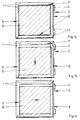
- Figures 1a to 1c show a window with two bars 1 of a fixed frame part and one against the Spars 1 of the fixed frame part pivotable wing 2.
- the wing 2 has two pivotable bars 3 with bearings 4 and one held by the pivotable bars 3 Disk part 5 with a disk 6.
- Figure 1a shows that Window in the closed position, in which the wing 2 with the Spars 1 of the fixed frame part are positively connected is.
- the spars 1 of the fixed frame part form a closed with the pivotable bars 3 Frame.
- the disc 6 is completely enclosed by the frame.
- the swiveling spars are for clarification 3 shown in longitudinal section.
- the spars 1, 3 each have Guides 7, 8 for the outer edge of the disc part 5.
- the disc part 5 is shown in the Closed position in the guides 7, 8 all Spars 1, 3.
- the pivotable spars 3 are over the Disc part 5 with the spars 1 of the fixed frame part positively connected.
- FIG. 1b shows the window in a ventilation position, in the a gap between the disc part 5 and the upper the fixed spars 1 is present.
- outgoing from the position of Figure 1a is the disc part 5 moved down until it was at the bottom of the guide 8 of the lower spar 3 rests.
- the form fit between the pivotable bars 3 of the frame part is over the disc part 5 and the left spar 1 of the fixed Frame part guaranteed.
- Figure 1c shows the window in an open position in the the disc part 5 completely from the guides 7 of the Spars 1 of the fixed frame part is moved out. This is the form fit between the swivel bars 3 and the spars 1 of the fixed frame part lifted. The wing 2 can thus be opened.
- the directions of movement of the Part 5 marked with arrows.
- the direction of movement from the ventilation position to the open position here is perpendicular to the direction of movement from the closed position to the ventilation position.
- Figures 2a to 2c show a further embodiment the window in a closed position, a ventilation position and an open position against a spar 9 a fixed frame part pivotable wing 10th
- This embodiment differs from that of FIGS Figures 1a to 1c mainly in that three pivotable Spars 11 arranged in a U-shape and bearings 12 of Wing 10 are attached to the base of the U and that the movement of a disk part 13 from the closed position straight into the open position. In a The middle position is therefore that shown in FIG. 2b Ventilation position.
- the disc part 13 has one Washer 14 with holding parts 15 arranged thereon Disk 14 is guided in guides 16 of the spars 9, 11.
- the spar 9 of the fixed frame part has the holding parts 15 corresponding recesses 18.
- the holding parts 15 are bolt-shaped and on the outer Edge of the disk 14 attached. If you start from the 2a, the disc 14 to the left moved, a ventilation gap shown in Figure 2b continuously adjust until the holding parts 15 from the area of the spar 9 of the fixed frame part out reach. Only in that shown in Figure 2c The holding parts 15 are complete when the window is open moved out of the spar 9 of the fixed frame part, so that a form fit through the disc part 13 between the movable bars 11 and the bars 9 of the fixed frame part is lifted.
- Figures 3a and 3b show an embodiment of the Window with one in a closed position and in one Ventilation position wing 19.
- Swiveling Spars 20 of the wing 19 are arranged in a U-shape and have in each case guides 21 for a disk part 22.
- the Disc part 22 represents in that shown in Figure 3a Position with a form fit of the pivotable spars 20 a spar 23 of a fixed frame part. Starting out from the closed position, the pane part can 22 move down so that between the top spar 20 and the disc part 22, a ventilation gap is formed. The form fit between the pivotable spars 20 and the spar 23 of the fixed frame part is thus in guaranteed in the closed position and in the ventilation position.
- Figures 3c and 3d show the window of Figure 3a in a section along the line III - III.
- Figure 3c is the form fit between the pivotable bars 20 and the spar 23 of the fixed frame part.
- the spar 23 of the fixed frame part has two a hinge 24 connected sections 25, 26. at the sections 25, 26 can be pivoted Release the positive connection with the disk part 22 and the wing 19 swivel. This marks the open position and is shown in Figure 3d.
- the embodiment of the window according to Figures 3a to 3d has the advantage that the movement of the wing 19 in the open position simply, for example by means of a not shown, on the spar 23 of the fixed Block part of the arranged lock can be blocked without to impede a continuously adjustable ventilation. This provides a security gain against violent opening the window in the ventilation position, since this from the outside without destroying the pane part 22 not possible.
- Figures 4a to 4c show a further embodiment the window in three positions of a wing 27.
- Disk part 28 has a form fit between U-shaped, pivotable spars 29, 30 and a spar 31 a fixed frame part.
- Two of the swivel Spars 29 have a common pivot / tilt bearing 32 on, while the upper of the spars 30 a pivot bearing 33 and the left spar 31 has a tilt bearing 34.
- the tipping bearing 34 and the pivot bearing 33 each have the pivot / tilt bearing 32 common, arranged at right angles to each other Axes.
- the spar 31 of the fixed frame part can therefore not be around the vertical axis of the swivel spars 29, 30 pivot.
- Figures 5a and 5b show a drive mechanism for a disk part 35 with an electric motor drive 36 for moving control elements 37.
- the control elements 37 are attached to the disc part 35 Holding parts 38 in engagement.
- the holding parts 38 support this Weight of the disk part 28 on guide curves 39 two Guide pieces 40 of the actuating elements 37 and have rolling elements 41 on.
- the electric motor drive 36 drives two threaded rods 42, one of which is a right-hand thread and the other has a left hand thread. hereby the guide curves 39 become relative to the holding parts 38 moves.
- Figure 5b shows the disc part 35 in one position lowered from its position from FIG. 5a, after the guide pieces 40 moved apart were.
- This drive mechanism is suitable, for example for moving the window from Figures 3a to 3d from the closed position to the ventilation position.
- Figures 6a to 6c show a drive mechanism with an electric motor drive 43, with which one Disc part 44 first to the right and then can move down.
- the disk part 44 has holding parts 45 with two rolling elements 47 and a bolt 48. Opposite the rolling elements 47 are two guide pieces 49 with guide curves 50 arranged fixed.
- the electromotive drive 43 moves via a threaded rod 51 one with the bolt 48 of the one holding part 45 telescopically connected actuator 52. This will Disc part 44 with the rolling elements 47 along the guide curves 50 led.
Landscapes
- Engineering & Computer Science (AREA)
- Mechanical Engineering (AREA)
- Civil Engineering (AREA)
- Structural Engineering (AREA)
- Window Of Vehicle (AREA)
- Wing Frames And Configurations (AREA)
- Specific Sealing Or Ventilating Devices For Doors And Windows (AREA)
Abstract
Description
- Fig.1a - 1c
- ein erfindungsgemäßes Fenster in drei Stellungen,
- Fig.2a - 2c
- eine weitere Ausführungsform des erfindungsgemäßen Fensters in drei Stellungen,
- Fig.3a, 3b
- eine weitere Ausführungsform des erfindungsgemäßen Fensters in zwei Stellungen.
- Fig.3c, 3d
- Schnittdarstellungen durch das Fenster aus Figur 3a in zwei Stellungen,
- Fig.4a - 4c
- eine weitere Ausführungsform des erfindungsgemäßen Fensters in drei Stellungen,
- Fig.5a, 5b
- einen Antriebsmechanismus zum Antrieb eines Scheibenteils des erfindungsgemäßen Fensters in zwei Stellungen,
- Fig.6a - 6c
- eine weitere Ausführungsform des Antriebsmechanismus.
Claims (31)
- Fenster oder Fenstertür mit einem von einer Schließstellung in eine Offenstellung schwenkbar gelagerten Flügel mit einem feststehenden Rahmenteil, mit einem eine Scheibe aufweisenden Scheibenteil des Flügels und mit Verriegelungsmitteln zur formschlüssigen Verbindung des Flügels mit dem feststehenden Rahmenteil in Schließstellung, dadurch gekennzeichnet, dass in Schließstellung Holme (1, 9, 23, 31) des feststehende Rahmenteils und des Flügels (2, 10, 19, 27) einen gemeinsamen Rahmen bilden und dass in Schließstellung das Scheibenteil (5, 22, 28, 35) die schwenkbaren Holme (3, 11, 20, 29, 30) mit den feststehenden Holmen (1, 9, 23, 31) formschlüssig verbindet.
- Fenster nach Anspruch 1, dadurch gekennzeichnet, dass einer der Holme (23) des feststehenden Rahmenteils zumindest einen beweglichen Abschnitt (26) aufweist und dass der bewegliche Abschnitt (26) von einer das Scheibenteil (22) in Schließstellung formschlüssig halternden Stellung in eine den Formschluss mit dem Scheibenteil (22) lösbare Stellung bewegbar ist.
- Fenster nach Anspruch 1 oder 2, dadurch gekennzeichnet, dass die Holme (1, 9, 31) des feststehenden Rahmenteils und die schwenkbaren Holme (3, 11, 29, 30) Führungen (7, 8, 16, 17) für das Scheibenteil (5, 13, 28) aufweisen und dass das Scheibenteil (5, 13, 28) zu seiner Bewegung in die Offenstellung aus den Führungen (7, 8, 16, 17) der Holme (1, 9, 31) des feststehenden Rahmenteils herausbewegbar ist.
- Fenster nach zumindest einem der vorhergehenden Ansprüche, dadurch gekennzeichnet, dass das Scheibenteil (5, 13, 22, 28) von der Schließstellung in eine Belüftungsstellung in seiner Ebene bewegbar ist.
- Fenster nach zumindest einem der vorhergehenden Ansprüche, dadurch gekennzeichnet, dass in der Belüftungsstellung das Scheibenteil (5, 13, 22, 28) die schwenkbaren Holme (3, 11, 20, 29, 30) mit den feststehenden Holmen (1, 9, 23, 31) formschlüssig verbindet.
- Fenster nach zumindest einem der vorhergehenden Ansprüche, dadurch gekennzeichnet, dass der bewegliche Abschnitt (26) des Holms (23) des feststehenden Rahmenteils über ein Scharnier (24) mit einem feststehenden Abschnitt (25) verbunden ist.
- Fenster nach zumindest einem der vorhergehenden Ansprüche, dadurch gekennzeichnet, dass der untere Holm (3, 11, 20, 29) mit den Lagerungen (4, 12, Dreh-/Kipplager 32) des Flügels (2, 10, 19, 27) verbunden ist.
- Fenster nach zumindest einem der vorhergehenden Ansprüche, dadurch gekennzeichnet, dass die schwenkbaren Holme (11, 20, 29, 30) das Scheibenteil (13, 22, 28) U-förmig umgreifen und dass eine Lagerung (4, 12, Dreh-/ Kipplager 32) des Flügels (10, 19, 27) an der Basis des U's angeordnet ist.
- Fenster nach zumindest einem der vorhergehenden Ansprüche, dadurch gekennzeichnet, dass jeweils zwei rechtwinklig zueinander angeordnete Holme (3, 29) feststehend und schwenkbar gehalten sind und dass das Scheibenteil (5, 28) zur Bewegung in die Belüftungsstellung von einem der Holme (1, 30, 31) der übrigen Holme weg verschiebbar ist und zur Bewegung in die Offenstellung von dem anderen der übrigen Holme (1, 30, 31) weg verschiebbar ist.
- Fenster nach zumindest einem der vorhergehenden Ansprüche, dadurch gekennzeichnet, dass in Belüftungsstellung einer der schwenkbaren Holme (30) an dem feststehenden Rahmenteil gehalten und von dem Scheibenteil (28) getrennt ist und die anderen Holme (29, 31) in eine Kippstellung des Scheibenteils (28) bewegbar sind.
- Fenster nach zumindest einem der vorhergehenden Ansprüche, dadurch gekennzeichnet, dass die zwei rechtwinklig zueinander angeordneten schwenkbaren Holme (29) ein Kipplager aufweisen, dass der der Lagerung (Dreh-/ Kipplager 32) der schwenkbaren Holme (29) gegenüberstehende Holm (31) des feststehenden Rahmenteils ein mit dem Kipplager (Dreh-/Kipplager 32) der schwenkbaren Holme (29) korrespondierendes Kipplager (34) hat, und dass in Belüftungsstellung das Scheibenteil (35) einen Formschluss zwischen den schwenkbaren Holmen (29) und dem das Kipplager (34) aufweisenden Holm (31) hat.
- Fenster nach zumindest einem der vorhergehenden Ansprüche, dadurch gekennzeichnet, dass in der Offenstellung des Flügels (27) der in Kippstellung feststehende Holm (30) mit den schwenkbaren Holmen (29) verbunden ist.
- Fenster nach zumindest einem der vorhergehenden Ansprüche, dadurch gekennzeichnet, dass zwei rechtwinklig zueinander angeordnete schwenkbare Holme (29) in ihrem Eckbereich ein gemeinsames Dreh-/Kipplager (32) und die anderen Holme (30, 31) mit dem Dreh-/Kipplager (32) korrespondierende Drehlager (33) und Kipplager (34) aufweisen.
- Fenster nach zumindest einem der vorhergehenden Ansprüche, dadurch gekennzeichnet, dass das Scheibenteil (13, 22) geradlinig in eine einzige Richtung bewegbar ist, wobei in einer Mittelstellung die Scheibe (14) des Scheibenteils (13, 22) einen Abstand von einem der Holme (9, 20) hat.
- Fenster nach zumindest einem der vorhergehenden Ansprüche, dadurch gekennzeichnet, dass das Scheibenteil (5, 28) in einer von der Richtung seiner Bewegung in die Belüftungsstellung abweichenden Richtung zur Lösung des Formschlusses mit den feststehenden Holmen (1, 31) bewegbar ist.
- Fenster nach zumindest einem der vorhergehenden Ansprüche, dadurch gekennzeichnet, dass das Scheibenteil (5, 13, 22, 28, ) zur Erzeugung des Formschlusses mit dem äußeren Rand der Scheibe (6, 14) in entsprechend gestaltete Führungen (7, 8, 16, 17, 21) der Holme (1, 3, 9, 11, 20, 23, 29, 30, 31) eindringt.
- Fenster nach zumindest einem der vorhergehenden Ansprüche, dadurch gekennzeichnet, dass die Holme (9) des feststehenden Rahmenteils Ausnehmungen (18) zur Aufnahme von entsprechend gestalteten, in radial äußeren Bereichen des Scheibenteils (13) angeordneten Halteteilen (15) haben.
- Fenster nach zumindest einem der vorhergehenden Ansprüche, dadurch gekennzeichnet, dass die Ausnehmungen (18) quer zur Schwenkrichtung des Scheibenteils (13) weisend angeordnet sind.
- Fenster nach zumindest einem der vorhergehenden Ansprüche, dadurch gekennzeichnet, dass das Scheibenteil (5, 13, 22, 28, 35, 44) einen eine Einfassung des den äußeren Randes der Scheibe (6, 14) bildenden Rand aus Metall oder Kunststoff aufweist.
- Fenster nach zumindest einem der vorhergehenden Ansprüche, dadurch gekennzeichnet, dass das Scheibenteil (5, 13, 22, 28) in die Führungen (8, 17, 21) oder Ausnehmungen (18) der schwenkbaren Holme (3, 11, 20) lösbar eingesetzt ist.
- Fenster nach zumindest einem der vorhergehenden Ansprüche, dadurch gekennzeichnet, dass die Ausnehmungen als Nuten und die Halteteile als äußerer Rand der Scheibe des Scheibenteils gestaltet sind.
- Fenster nach zumindest einem der vorhergehenden Ansprüche, dadurch gekennzeichnet, dass die Halteteile (45) als an dem äußeren Rand der Scheibe angeordnete Bolzen (48) ausgebildet sind.
- Fenster nach zumindest einem der vorhergehenden Ansprüche, dadurch gekennzeichnet, dass einem der Holme bewegbare und mit den Halteteilen (38, 45, 46) des Scheibenteils (35, 44) korrespondierende Stellelemente (37, 52) angeordnet sind.
- Fenster nach zumindest einem der vorhergehenden Ansprüche, dadurch gekennzeichnet, dass die Stellelemente (37, 52) Führungsstücke (40, 49) mit einer Führungskurve (39, 50) aufweisen.
- Fenster nach zumindest einem der vorhergehenden Ansprüche, dadurch gekennzeichnet, dass die Führungsstücke (40, 49) zur Abstützung des Scheibenteils (35, 44) gestaltet sind.
- Fenster nach zumindest einem der vorhergehenden Ansprüche, dadurch gekennzeichnet, dass die Halteteile (38, 45, 46) Gleitelemente oder Rollelemente (41, 47) aufweisen.
- Fenster nach zumindest einem der vorhergehenden Ansprüche, dadurch gekennzeichnet, dass Führungskurven in Nuten der Führungsstücke angeordnet sind und die Halteteile in die Nuten eindringende Kulissensteine aufweisen.
- Fenster nach zumindest einem der vorhergehenden Ansprüche, dadurch gekennzeichnet, dass ein elektromotorischer Antrieb (36, 43) zur Bewegung der Führungsstücke (40) und/oder von mit den Halteteilen (45) korrespondierenden Stellelementen (52) gestaltet ist.
- Fenster nach zumindest einem der vorhergehenden Ansprüche, dadurch gekennzeichnet, dass der Antrieb (36, 43) eine Gewindestange (42, 51) aufweist.
- Fenster nach zumindest einem der vorhergehenden Ansprüche, dadurch gekennzeichnet, dass die Gewindestange (42) auf einer Seite des elektromotorischen Antriebs (36) ein Linksgewinde und auf seiner anderen Seite ein Rechtsgewinde hat, dass auf beiden Seiten des Antriebs (36) jeweils ein Führungsstück (40) angeordnet ist und dass die Führungskurven (39) der Führungsstücke (40) entgegengesetzt zueinander angeordnet sind.
- Fenster nach zumindest einem der vorhergehenden Ansprüche, dadurch gekennzeichnet, dass eine von Hand bewegbare Treibstange mit den Führungsstücken und/oder von mit den Halteteilen korrespondierenden Stellelementen verbunden ist.
Applications Claiming Priority (2)
| Application Number | Priority Date | Filing Date | Title |
|---|---|---|---|
| DE10140558A DE10140558A1 (de) | 2001-08-17 | 2001-08-17 | Fenster oder Fenstertür |
| DE10140558 | 2001-08-17 |
Publications (2)
| Publication Number | Publication Date |
|---|---|
| EP1286014A1 true EP1286014A1 (de) | 2003-02-26 |
| EP1286014B1 EP1286014B1 (de) | 2004-10-27 |
Family
ID=7695870
Family Applications (1)
| Application Number | Title | Priority Date | Filing Date |
|---|---|---|---|
| EP20020014760 Expired - Lifetime EP1286014B1 (de) | 2001-08-17 | 2002-07-04 | Fenster oder Fenstertür mit Hilfe der Glasscheibe verriegelt |
Country Status (3)
| Country | Link |
|---|---|
| EP (1) | EP1286014B1 (de) |
| AT (1) | ATE280887T1 (de) |
| DE (2) | DE10140558A1 (de) |
Cited By (1)
| Publication number | Priority date | Publication date | Assignee | Title |
|---|---|---|---|---|
| FR2922469A1 (fr) * | 2007-10-22 | 2009-04-24 | Noroit Sarl | Hotte filtrante,telle qu'une hotte a flux laminaire |
Families Citing this family (1)
| Publication number | Priority date | Publication date | Assignee | Title |
|---|---|---|---|---|
| DE102016116646A1 (de) | 2016-09-06 | 2018-03-08 | Matthias Plath | Tür mit Riegel |
Citations (4)
| Publication number | Priority date | Publication date | Assignee | Title |
|---|---|---|---|---|
| US2744593A (en) * | 1955-02-16 | 1956-05-08 | John P Travis | Pivoted reversible window with laterally and transversely shiftable pivot |
| BE564332A (de) * | 1957-01-31 | 1958-02-15 | ||
| DE1150791B (de) * | 1961-03-22 | 1963-06-27 | Heinrich Hebgen | Fenster, Tuer od. dgl. mit schwenkbaren und fuer den dichten Abschluss in seiner Ebene eine kurze Strecke verschiebbaren Fluegeln |
| US4041644A (en) * | 1975-10-07 | 1977-08-16 | Alcanzare Eduardo V | Reversible window |
Family Cites Families (8)
| Publication number | Priority date | Publication date | Assignee | Title |
|---|---|---|---|---|
| US2182008A (en) * | 1938-10-06 | 1939-12-05 | Trombetta Nicola | Window frame construction |
| US2181215A (en) * | 1938-11-05 | 1939-11-28 | Sweany Linnie | Swinging window |
| DE1802163C3 (de) * | 1968-10-09 | 1978-11-30 | Wilh. Frank Gmbh, 7022 Leinfelden | Schiebe-Schwenk-Kippfenster |
| DE3920239A1 (de) * | 1989-06-21 | 1991-01-03 | Geze Gmbh & Co | Getriebe fuer ein betaetigungsgestaenge einer ausstellvorrichtung eines fensters |
| DE4125834C2 (de) * | 1991-08-03 | 1994-03-10 | Kunert Heinz | Fenster mit aufklappbarem Fensterflügel |
| DE9218791U1 (de) * | 1992-11-27 | 1995-07-13 | Zoller, Fritz, 70771 Leinfelden-Echterdingen | Vorrichtung zum Kippen oder Verschwenken von Fenstern, Türen, Rolladen o.dgl. |
| DE29522032U1 (de) * | 1995-02-24 | 1999-05-06 | Al Bohn Fenstersysteme GmbH, 74889 Sinsheim | Fenster |
| DE19860849C2 (de) * | 1998-12-31 | 2002-10-24 | Paul Baier | Vorrichtung zum wechselweisen Öffnen und Schließen einer Öffnung, insbesondere Fenster, Tür oder dergleichen |
-
2001
- 2001-08-17 DE DE10140558A patent/DE10140558A1/de not_active Withdrawn
-
2002
- 2002-07-04 DE DE50201388T patent/DE50201388D1/de not_active Expired - Lifetime
- 2002-07-04 AT AT02014760T patent/ATE280887T1/de not_active IP Right Cessation
- 2002-07-04 EP EP20020014760 patent/EP1286014B1/de not_active Expired - Lifetime
Patent Citations (4)
| Publication number | Priority date | Publication date | Assignee | Title |
|---|---|---|---|---|
| US2744593A (en) * | 1955-02-16 | 1956-05-08 | John P Travis | Pivoted reversible window with laterally and transversely shiftable pivot |
| BE564332A (de) * | 1957-01-31 | 1958-02-15 | ||
| DE1150791B (de) * | 1961-03-22 | 1963-06-27 | Heinrich Hebgen | Fenster, Tuer od. dgl. mit schwenkbaren und fuer den dichten Abschluss in seiner Ebene eine kurze Strecke verschiebbaren Fluegeln |
| US4041644A (en) * | 1975-10-07 | 1977-08-16 | Alcanzare Eduardo V | Reversible window |
Cited By (1)
| Publication number | Priority date | Publication date | Assignee | Title |
|---|---|---|---|---|
| FR2922469A1 (fr) * | 2007-10-22 | 2009-04-24 | Noroit Sarl | Hotte filtrante,telle qu'une hotte a flux laminaire |
Also Published As
| Publication number | Publication date |
|---|---|
| EP1286014B1 (de) | 2004-10-27 |
| DE50201388D1 (de) | 2004-12-02 |
| ATE280887T1 (de) | 2004-11-15 |
| DE10140558A1 (de) | 2003-02-27 |
Similar Documents
| Publication | Publication Date | Title |
|---|---|---|
| DE8702660U1 (de) | Fenster- oder Tür-Konstruktion mit einem bewegbar gehaltenen, verriegelbaren Flügel | |
| DE202014000876U1 (de) | Beschlag eines zumindest hebbaren, vorzugsweise aber auch verschiebbaren Flügels von Fenstern oder Türen | |
| EP1312743B1 (de) | Sperr- und Sicherungsvorrichtung für einen Hebe- und Schiebeflügel; Treibstangenbeschlag mit einer solchen Vorrichtung; Hebe- und Schiebetür bzw. -fenster mit einer solchen Vorrichtung | |
| EP0628691B2 (de) | Dreh-Kipp-Beschlag für Fenster, Türen od.dgl. | |
| DE69328827T2 (de) | Schiebefenster, bestehend aus mindestens einem rahmen mit einem darin vertikal verschiebbaren flügel | |
| EP0027261B1 (de) | Kipp-Schiebebeschlag für Fenster und Türen oder dgl. | |
| EP0096744A2 (de) | Drehkippbeschlag | |
| EP1286014B1 (de) | Fenster oder Fenstertür mit Hilfe der Glasscheibe verriegelt | |
| DE2810058A1 (de) | Riegelschloss | |
| EP1728956B2 (de) | Gegen ein Aushebeln von aussen sichernder Beschlag für eine Hebe-Schiebe-Tür | |
| WO2002063123A1 (de) | Verschluss -und scharniersystem und -vorrichtung | |
| DE4038669C2 (de) | Zum Öffnen eingerichtete Schiebe-Faltwand | |
| DE69300882T3 (de) | Ausziehbares Gitter für Tür- und Fenster-Protektion. | |
| DE3887677T2 (de) | Drehkippfenster mit drei Öffnungsmöglichkeiten. | |
| DE19929818A1 (de) | Beschlag für ein Fenster oder eine Tür mit einer Spaltöffnungsstellung | |
| DE19744514B4 (de) | Schiebetüranlage mit wenigstens einem schieb- und schwenkbaren Türflügel | |
| EP1503013A2 (de) | Fenster | |
| DE4312955A1 (de) | Ausstelleinrichtung für kipp- und schwenkbare Fenster | |
| DE19909365A1 (de) | Vorrichtung zum Feststellen und Verriegeln von Türen oder Wandelementen | |
| CH688103A5 (de) | Tuer. | |
| EP0098933B1 (de) | Beschlag für den zumindest heb- und kippbaren Flügel eines Fensters, einer Tür od. dgl. | |
| DE2531701A1 (de) | Gelenk und eine gelenk- und drehzapfenanordnung | |
| DE1559736A1 (de) | An- und Abdruckvorrichtung fuer die Fluegel von Kipp-Schwenkfenstern,-tueren od.dgl. | |
| DE1659788A1 (de) | Vertikales Schiebefenster | |
| DE8716902U1 (de) | Fenster mit wenigstens zwei öffenbaren Fensterflügeln |
Legal Events
| Date | Code | Title | Description |
|---|---|---|---|
| PUAI | Public reference made under article 153(3) epc to a published international application that has entered the european phase |
Free format text: ORIGINAL CODE: 0009012 |
|
| AK | Designated contracting states |
Kind code of ref document: A1 Designated state(s): AT BE BG CH CY CZ DE DK EE ES FI FR GB GR IE IT LI LU MC NL PT SE SK TR |
|
| AX | Request for extension of the european patent |
Extension state: AL LT LV MK RO SI |
|
| 17P | Request for examination filed |
Effective date: 20030626 |
|
| AKX | Designation fees paid |
Designated state(s): AT BE BG CH CY CZ DE DK EE ES FI FR GB GR IE IT LI LU MC NL PT SE SK TR |
|
| 17Q | First examination report despatched |
Effective date: 20031113 |
|
| GRAP | Despatch of communication of intention to grant a patent |
Free format text: ORIGINAL CODE: EPIDOSNIGR1 |
|
| GRAS | Grant fee paid |
Free format text: ORIGINAL CODE: EPIDOSNIGR3 |
|
| GRAA | (expected) grant |
Free format text: ORIGINAL CODE: 0009210 |
|
| AK | Designated contracting states |
Kind code of ref document: B1 Designated state(s): AT BE BG CH CY CZ DE DK EE ES FI FR GB GR IE IT LI LU MC NL PT SE SK TR |
|
| PG25 | Lapsed in a contracting state [announced via postgrant information from national office to epo] |
Ref country code: CZ Free format text: LAPSE BECAUSE OF FAILURE TO SUBMIT A TRANSLATION OF THE DESCRIPTION OR TO PAY THE FEE WITHIN THE PRESCRIBED TIME-LIMIT Effective date: 20041027 Ref country code: GB Free format text: LAPSE BECAUSE OF FAILURE TO SUBMIT A TRANSLATION OF THE DESCRIPTION OR TO PAY THE FEE WITHIN THE PRESCRIBED TIME-LIMIT Effective date: 20041027 Ref country code: BG Free format text: LAPSE BECAUSE OF FAILURE TO SUBMIT A TRANSLATION OF THE DESCRIPTION OR TO PAY THE FEE WITHIN THE PRESCRIBED TIME-LIMIT Effective date: 20041027 Ref country code: FI Free format text: LAPSE BECAUSE OF FAILURE TO SUBMIT A TRANSLATION OF THE DESCRIPTION OR TO PAY THE FEE WITHIN THE PRESCRIBED TIME-LIMIT Effective date: 20041027 Ref country code: TR Free format text: LAPSE BECAUSE OF FAILURE TO SUBMIT A TRANSLATION OF THE DESCRIPTION OR TO PAY THE FEE WITHIN THE PRESCRIBED TIME-LIMIT Effective date: 20041027 Ref country code: SK Free format text: LAPSE BECAUSE OF FAILURE TO SUBMIT A TRANSLATION OF THE DESCRIPTION OR TO PAY THE FEE WITHIN THE PRESCRIBED TIME-LIMIT Effective date: 20041027 Ref country code: IE Free format text: LAPSE BECAUSE OF FAILURE TO SUBMIT A TRANSLATION OF THE DESCRIPTION OR TO PAY THE FEE WITHIN THE PRESCRIBED TIME-LIMIT Effective date: 20041027 Ref country code: EE Free format text: LAPSE BECAUSE OF FAILURE TO SUBMIT A TRANSLATION OF THE DESCRIPTION OR TO PAY THE FEE WITHIN THE PRESCRIBED TIME-LIMIT Effective date: 20041027 |
|
| REG | Reference to a national code |
Ref country code: GB Ref legal event code: FG4D Free format text: NOT ENGLISH |
|
| REG | Reference to a national code |
Ref country code: CH Ref legal event code: EP |
|
| REG | Reference to a national code |
Ref country code: IE Ref legal event code: FG4D Free format text: GERMAN |
|
| REF | Corresponds to: |
Ref document number: 50201388 Country of ref document: DE Date of ref document: 20041202 Kind code of ref document: P |
|
| PG25 | Lapsed in a contracting state [announced via postgrant information from national office to epo] |
Ref country code: GR Free format text: LAPSE BECAUSE OF FAILURE TO SUBMIT A TRANSLATION OF THE DESCRIPTION OR TO PAY THE FEE WITHIN THE PRESCRIBED TIME-LIMIT Effective date: 20050127 Ref country code: DK Free format text: LAPSE BECAUSE OF FAILURE TO SUBMIT A TRANSLATION OF THE DESCRIPTION OR TO PAY THE FEE WITHIN THE PRESCRIBED TIME-LIMIT Effective date: 20050127 Ref country code: SE Free format text: LAPSE BECAUSE OF FAILURE TO SUBMIT A TRANSLATION OF THE DESCRIPTION OR TO PAY THE FEE WITHIN THE PRESCRIBED TIME-LIMIT Effective date: 20050127 |
|
| PG25 | Lapsed in a contracting state [announced via postgrant information from national office to epo] |
Ref country code: ES Free format text: LAPSE BECAUSE OF FAILURE TO SUBMIT A TRANSLATION OF THE DESCRIPTION OR TO PAY THE FEE WITHIN THE PRESCRIBED TIME-LIMIT Effective date: 20050207 |
|
| REG | Reference to a national code |
Ref country code: IE Ref legal event code: FD4D |
|
| GBV | Gb: ep patent (uk) treated as always having been void in accordance with gb section 77(7)/1977 [no translation filed] |
Effective date: 20041027 |
|
| ET | Fr: translation filed | ||
| PG25 | Lapsed in a contracting state [announced via postgrant information from national office to epo] |
Ref country code: LU Free format text: LAPSE BECAUSE OF NON-PAYMENT OF DUE FEES Effective date: 20050704 Ref country code: CY Free format text: LAPSE BECAUSE OF FAILURE TO SUBMIT A TRANSLATION OF THE DESCRIPTION OR TO PAY THE FEE WITHIN THE PRESCRIBED TIME-LIMIT Effective date: 20050704 |
|
| PG25 | Lapsed in a contracting state [announced via postgrant information from national office to epo] |
Ref country code: BE Free format text: LAPSE BECAUSE OF NON-PAYMENT OF DUE FEES Effective date: 20050731 Ref country code: MC Free format text: LAPSE BECAUSE OF NON-PAYMENT OF DUE FEES Effective date: 20050731 |
|
| PLBE | No opposition filed within time limit |
Free format text: ORIGINAL CODE: 0009261 |
|
| STAA | Information on the status of an ep patent application or granted ep patent |
Free format text: STATUS: NO OPPOSITION FILED WITHIN TIME LIMIT |
|
| 26N | No opposition filed |
Effective date: 20050728 |
|
| PGFP | Annual fee paid to national office [announced via postgrant information from national office to epo] |
Ref country code: NL Payment date: 20060725 Year of fee payment: 5 |
|
| PG25 | Lapsed in a contracting state [announced via postgrant information from national office to epo] |
Ref country code: LI Free format text: LAPSE BECAUSE OF NON-PAYMENT OF DUE FEES Effective date: 20060731 Ref country code: CH Free format text: LAPSE BECAUSE OF NON-PAYMENT OF DUE FEES Effective date: 20060731 |
|
| REG | Reference to a national code |
Ref country code: CH Ref legal event code: PL |
|
| BERE | Be: lapsed |
Owner name: AUG. *WINKHAUS G.M.B.H. & CO. K.G. Effective date: 20050731 |
|
| PG25 | Lapsed in a contracting state [announced via postgrant information from national office to epo] |
Ref country code: PT Free format text: LAPSE BECAUSE OF NON-PAYMENT OF DUE FEES Effective date: 20050327 |
|
| NLV4 | Nl: lapsed or anulled due to non-payment of the annual fee |
Effective date: 20080201 |
|
| PG25 | Lapsed in a contracting state [announced via postgrant information from national office to epo] |
Ref country code: NL Free format text: LAPSE BECAUSE OF NON-PAYMENT OF DUE FEES Effective date: 20080201 |
|
| PGFP | Annual fee paid to national office [announced via postgrant information from national office to epo] |
Ref country code: AT Payment date: 20100720 Year of fee payment: 9 Ref country code: FR Payment date: 20100802 Year of fee payment: 9 Ref country code: IT Payment date: 20100723 Year of fee payment: 9 |
|
| REG | Reference to a national code |
Ref country code: AT Ref legal event code: MM01 Ref document number: 280887 Country of ref document: AT Kind code of ref document: T Effective date: 20110704 |
|
| REG | Reference to a national code |
Ref country code: FR Ref legal event code: ST Effective date: 20120330 |
|
| PG25 | Lapsed in a contracting state [announced via postgrant information from national office to epo] |
Ref country code: FR Free format text: LAPSE BECAUSE OF NON-PAYMENT OF DUE FEES Effective date: 20110801 |
|
| PG25 | Lapsed in a contracting state [announced via postgrant information from national office to epo] |
Ref country code: IT Free format text: LAPSE BECAUSE OF NON-PAYMENT OF DUE FEES Effective date: 20110704 |
|
| PGFP | Annual fee paid to national office [announced via postgrant information from national office to epo] |
Ref country code: DE Payment date: 20120809 Year of fee payment: 11 |
|
| PG25 | Lapsed in a contracting state [announced via postgrant information from national office to epo] |
Ref country code: AT Free format text: LAPSE BECAUSE OF NON-PAYMENT OF DUE FEES Effective date: 20110704 |
|
| PG25 | Lapsed in a contracting state [announced via postgrant information from national office to epo] |
Ref country code: DE Free format text: LAPSE BECAUSE OF NON-PAYMENT OF DUE FEES Effective date: 20140201 |
|
| REG | Reference to a national code |
Ref country code: DE Ref legal event code: R119 Ref document number: 50201388 Country of ref document: DE Effective date: 20140201 |