EP1285762A2 - Tropfenerzeuger für Mikrotropfen, insbesondere Düsenkopf für Tintendrucker - Google Patents
Tropfenerzeuger für Mikrotropfen, insbesondere Düsenkopf für Tintendrucker Download PDFInfo
- Publication number
- EP1285762A2 EP1285762A2 EP02010897A EP02010897A EP1285762A2 EP 1285762 A2 EP1285762 A2 EP 1285762A2 EP 02010897 A EP02010897 A EP 02010897A EP 02010897 A EP02010897 A EP 02010897A EP 1285762 A2 EP1285762 A2 EP 1285762A2
- Authority
- EP
- European Patent Office
- Prior art keywords
- bending
- drop generator
- liquid
- generator according
- opening
- Prior art date
- Legal status (The legal status is an assumption and is not a legal conclusion. Google has not performed a legal analysis and makes no representation as to the accuracy of the status listed.)
- Granted
Links
- 238000005452 bending Methods 0.000 claims abstract description 74
- 239000007788 liquid Substances 0.000 claims abstract description 52
- 239000012530 fluid Substances 0.000 claims abstract description 15
- 239000011324 bead Substances 0.000 claims description 17
- 238000005096 rolling process Methods 0.000 claims description 7
- 238000004519 manufacturing process Methods 0.000 claims description 5
- 238000005192 partition Methods 0.000 description 6
- 210000002105 tongue Anatomy 0.000 description 2
- 239000000853 adhesive Substances 0.000 description 1
- 238000004026 adhesive bonding Methods 0.000 description 1
- 230000001070 adhesive effect Effects 0.000 description 1
- 238000013459 approach Methods 0.000 description 1
- 230000005540 biological transmission Effects 0.000 description 1
- 230000015572 biosynthetic process Effects 0.000 description 1
- 238000013016 damping Methods 0.000 description 1
- 230000000694 effects Effects 0.000 description 1
- 239000000945 filler Substances 0.000 description 1
- 230000036571 hydration Effects 0.000 description 1
- 238000006703 hydration reaction Methods 0.000 description 1
Images

Classifications
-
- B—PERFORMING OPERATIONS; TRANSPORTING
- B41—PRINTING; LINING MACHINES; TYPEWRITERS; STAMPS
- B41J—TYPEWRITERS; SELECTIVE PRINTING MECHANISMS, i.e. MECHANISMS PRINTING OTHERWISE THAN FROM A FORME; CORRECTION OF TYPOGRAPHICAL ERRORS
- B41J2/00—Typewriters or selective printing mechanisms characterised by the printing or marking process for which they are designed
- B41J2/005—Typewriters or selective printing mechanisms characterised by the printing or marking process for which they are designed characterised by bringing liquid or particles selectively into contact with a printing material
- B41J2/01—Ink jet
- B41J2/135—Nozzles
- B41J2/14—Structure thereof only for on-demand ink jet heads
- B41J2/14201—Structure of print heads with piezoelectric elements
- B41J2/14282—Structure of print heads with piezoelectric elements of cantilever type
Definitions
- the invention relates to a drop generator for microdrops, in particular one Nozzle head for ink printers, with groups of piezoelectric arranged in a housing actuatable bending transducers that are spaced apart from one another Partial length are guided laterally into recesses by means of wall thicknesses, whereby longitudinal longitudinal liquid channels under the bending fingers in a frame plate are arranged and in the base plate a liquid chamber is formed, at least one nozzle opens into each bending transducer.
- the drop generator described at the outset is known from EP 0 713 773 A2.
- the known design uses partitions in full length and height corresponding wall thicknesses between the parallel bending transducers. It can therefore be assumed that there is a microdrop generator for an ink printer, with a piezoelectric bending transducer in a housing, with a Bending comb, the rear, passive area with a transverse connecting dam is equipped and its front, active area from bending tongues exists, which are assigned to the nozzles, wherein the bending transducer consists of a carrier layer and consists of a connected piezoelectric layer and on it A step cutout next to the underside in the passive section of the carrier layer has a hole for a pin, so that a protruding support section is formed.
- This training serves the goal of avoiding the so-called crosstalk from bending converter chamber to bending converter chamber in a front, area facing the nozzles that allows lateral liquid pressure waves, disturbances in the formation of drops of liquid intended to be adhered to Time, the ejection angle and the frequency of the bending transducers occur to avoid.
- the invention has for its object a crosstalk between individuals Chambers without complex and difficult to control placement of partitions Avoid between the bending fingers, with a bending transducer in each chamber is located, the bending tongue against the associated nozzle in the common Base plate deflects, and with sufficiently thick chamber walls, in one a manageable ⁇ m range for tight assembly in production To achieve liquid flow.
- the object is achieved according to the invention in that in each case one Opening of the liquid chamber is a bead that acts as a stroke limitation for serves the bending finger and that at the opening a shaft at least in width of the bending finger and in height up to the base plate.
- the achieved thereby large liquid inlet on the liquid chamber causes an efficient Fluid flow. This flow of liquid reduces the pressures on the surrounding walls. Unwanted high pressure waves are avoided.
- the full flow width must only be expected with a low flow resistance become. Since the walls close tightly at the bottom, the problem arises Not mastering manufacturing tolerances in the ⁇ m range.
- a special improvement is achieved by the bead: the fluid flow can be sheared off and thereby the amount of liquid ejected is sharply limited. With circulation the interior of the bead is sealed down to the lower edge of the bending transducer. This gives further advantages to fluctuations in pressure and temperature achieved.
- the overlying bending finger thus represents a seal, so that no liquid can escape due to pressure and temperature fluctuations.
- the fluid supply is supported by the fact that a common liquid inlet in the housing above the group of bending fingers is arranged.
- the liquid supply is further improved by the fact that the liquid longitudinal channels under the bending fingers in an area facing away from the nozzles to a fluid supply line running across the bending fingers (usually perpendicular) are connected.
- the Liquid chamber in the frame plate below the bead with the width of the (Inlet) opening is continued and is at right angles to the mouth of the nozzle extends.
- An embodiment further provides that the nozzles are in a on the housing and / or the frame plate and / or the base plate arranged nozzle plate is.
- the direction of exit of the liquid drops is e.g. taking into account that the nozzle plate with nozzles running vertically through the base plate on the Bottom of the base plate is arranged.
- a separator runs in the frame plate. This will spread the pressure and crosstalk to the neighboring chamber down to areas with small bending finger deflections reduced.
- the separator can be between two side by side Edge beads are connected.
- a further embodiment is that between two, during the Production of a bending finger formed by a saw cut incorporated a saw gap is the width of the thickness of a chamber partition or the thickness corresponds to a separator.
- the drop generator has a plurality of bending transducers 1 arranged in series, which are each formed from a piezo plate 3 glued to a frame plate 2 and then by sawing into individual bending transducers 1 depending on the Distance between two nozzles 7 are separated.
- the frame plate 2 has areas for fixing the piezo plate 3, which has a bearing edge 4 for a bending finger 5 form and other areas in which the bending fingers 5 from a biased Quickly move position to a relaxed position, one drop at a time 6 to exit through a nozzle 7.
- bimorph Multilayer piezo plate 3a can also be a bending comb in which the piezo plate 3 is provided with a connecting dam 9 and then the individual bending fingers 5 can be produced by sawing on the with cutouts, paragraphs, approaches and edges (so-called structures) provided frame plate 2 are placed.
- the connecting dam 9 is aligned, centered and fixed, e.g. by gluing or clamps.
- the adhesive surface for the bending transducer 1 is about 1/3 of its total length. This results in an alignment effect on the free-standing bending finger 5th
- the frame plate 2 has the bearing 10 for the bending transducer 1 and aids to align for the group divided into individual bending transducers 1.
- the group the bending transducer 1 is tightly enclosed by a housing 11.
- Liquid longitudinal channels 12 arranged in the base plate 1a in a liquid chamber 13 ends.
- Each liquid chamber 13 has at least one nozzle 7 on.
- the hydration is inter alia influenced by an opening 14.
- the opening 14 has the largest possible square (or rectangular) cross section, the from the structural dimensions between the bending fingers 5 and the nozzle distances results.
- A runs around the opening 14 of the liquid chamber 13
- Edge bead 15 which is located in the area of the greatest deflection of the bending finger 5, which consequently serves as a stroke limitation for the bending finger 5.
- At the opening 14 closes a shaft 16 at least in the width of the bending finger 5 and in height to the base plate 1a.
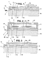
- the shaft 16 is without significant restriction up to Nozzle 7 out. The fluid flow is redirected when the drops emerge at the end (Fig. 1 - 3).
- a sufficient amount of liquid is basically provided by by a common liquid inlet in the housing 11 above the group of bending fingers 5 17 is arranged (Fig. 2).
- the liquid longitudinal channels 12 under the bending fingers 5 in an area facing away from the nozzles 7 to a fluid supply line 18 running transversely or perpendicularly to the bending fingers 5 connected.
- the liquid chamber 13 in the frame plate 2 sits below the bead 15 continues with the width 14a and extends in the exemplary embodiment of FIG. 2 at right angles to the mouth 19 of the nozzle 7.
- the nozzle 7 can in a on the housing 11 and / or the frame plate 2 and / or the base plate 1 a placed nozzle plate 20 may be arranged.
- the nozzle plate 20 arranged on the underside of the base plate 1 a. This allows the nozzle geometry can be optimized without restrictions.
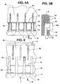
- a separating web 21 runs in each case on the edge bead 15 in the frame plate 2.
- the deep shafts 16 are separated from one another by these dividers 21.
- a pressure wave emerges into the effective range of an adjacent bending transducer 1 can be further reduced. It is advisable to form the dividers only in the area of the liquid chamber 13 and not to lead to the bearing edge 4. This will cause the liquid flow to drop below the Bending finger 5 ensured and a washable filler under the piezo plate 3 can be easily inserted and removed after a saw cut 23.
- the piezo plate 3 is stuck on, it can be supported on the separating webs 21, so that an exact distance dimension of the piezo plate 3 is achieved.
- a saw gap 23a is incorporated, the width of which Thickness of a partition wall 8 or the thickness of a separating web 21 corresponds.
- a side air gap can be created during sawing, so that the fluid when actuated is not trapped under the bending finger 5 and the movement attenuates.
- the bending fingers 5 are narrower than the distance by a minimum tolerance the dividers 21.
Landscapes
- Particle Formation And Scattering Control In Inkjet Printers (AREA)
- Coating Apparatus (AREA)
Abstract
Description
- Fig. 1
- eine Längsschnitt durch den Biegewandler mit Grundplatte, Rahmenplatte, Flüssigkeitskammer und Düse,
- Fig. 2
- denselben Schnitt wie Fig. 1 mit einem Gehäuse,
- Fig. 3
- denselben Schnitt mit einer angeformten Düse,
- Fig. 4A
- einen Teilschnitt in Richtung der Düsen mit Flüssigkeitskammer und Trennstegen,
- Fig. 4B
- einen Teilschnitt in Richtung der Düsen in einer Ebene, in der Flüssigkeit in eine Nachbar-Flüssigkeitskammer gelangen kann,
- Fig. 4C
- einen Teilschnitt in Richtung der Düsen bei Aufliegen der Biegefinger auf der Flüssigkeitskammer,
- Fig. 5A
- eine Draufsicht auf die Rahmenplatte mit den Trennstegen,
- Fig. 5B
- einen Schnitt durch Fig. 5A in der Ebene der Flüssigkeitskammer und
- Fig. 6
- eine Draufsicht auf die Rahmenplatte mit den Abrollflächen.
- 1
- Biegewandler
- 1a
- Grundplatte
- 2
- Rahmenplatte
- 3
- Piezo-Platte
- 3a
- Multilayer (passiv)
- 3b
- Multilayer (aktiv)
- 4
- Lagerkante
- 5
- Biegefinger
- 6
- Flüssigkeitstropfen (Mikrotropfen)
- 7
- Düse
- 8
- Kammerzwischenwand
- 9
- Verbindungsdamm
- 10
- Lagerstelle
- 11
- Gehäuse
- 12
- Flüssigkeits-Längskanäle
- 13
- Flüssigkeitskammer
- 14
- Öffnung
- 14a
- Weite
- 15
- Randwulst
- 16
- Schacht
- 17
- Flüssigkeitseinlass
- 18
- Fluidzuleitung
- 19
- Mündung der Düse
- 20
- Düsenplatte
- 21
- Trennsteg
- 22
- Abrollfläche
- 23
- Sägeschnitt
- 23a
- Sägespalt
Claims (10)
- Tropfenerzeuger für Mikrotropfen, insbesondere Düsenkopf für Tintendrucker, mit in einem Gehäuse (11) angeordneten Gruppen von piezoelektrisch betätigbaren Biegewandlern (1), die voneinander beabstandet auf eine Teillänge mittels Wanddicken getrennt in Ausnehmungen geführt sind, wobei unter den Biegefingern (5) in einer Rahmenplatte (2) in Längsrichtung verlaufende Flüssigkeits-Längskanäle (12) angeordnet sind und in der Grundplatte (1a) eine Flüssigkeitskammer ( 13) gebildet ist, in die jeweils pro Biegewandler (1) zumindest eine Düse (7) mündet,
dadurch gekennzeichnet, dass jeweils um eine Öffnung (14) der Flüssigkeitskammer (13) ein Randwulst (15) verläuft, der als Hubbegrenzung für den Biegefinger (5) dient und dass an die Öffnung (14) ein Schacht (16) zumindest in der Breite des Biegefingers (5) und in der Höhe bis zur Grundplatte (1a) anschließt. - Tropfenerzeuger nach Anspruch 1,
dadurch gekennzeichnet, dass im Gehäuse (11) über der Gruppe von Biegefingern (5) ein gemeinsamer Flüssigkeitseinlass (17) angeordnet ist. - Tropfenerzeuger nach einem der Ansprüche 1 oder 2,
dadurch gekennzeichnet, dass die Flüssigkeits-Längskanäle (12) unter den Biegefingern (5) in einem zu den Düsen (7) abgewandten Bereich an eine zu den Biegefingern (5) quer verlaufende Fluidzuleitung (18) angeschlossen sind. - Tropfenerzeuger nach einem der Ansprüche 1 bis 3,
dadurch gekennzeichnet, dass die Flüssigkeitskammer (13) in der Rahmenplatte (2) unterhalb dem Randwulst (15) mit der Weite (14a) der Öffnung (14) fortgesetzt ist und sich rechtwinklig bis zur Mündung (19) der Düse (7) erstreckt. - Tropfenerzeuger nach einem der Ansprüche 1 bis 4,
dadurch gekennzeichnet, dass die Düsen (7) in einer auf das Gehäuse (11) und / oder die Rahmenplatte (2) und / oder die Grundplatte (1a) aufgesetzten Düsenplatte (20) angeordnet sind. - Tropfenerzeuger nach einem der Ansprüche 1 bis 4,
dadurch gekennzeichnet, dass die Düsenplatte (20) bei senkrecht durch die Grundplatte (1 a) verlaufenden Düsen (7) an der Unterseite der Grundplatte (1a) angeordnet ist. - Tropfenerzeuger nach einem der Ansprüche 1 bis 6,
dadurch gekennzeichnet, dass an dem Randwulst (15) jeweils ein Trennsteg (21) in der Rahmenplatte (2) verläuft. - Tropfenerzeuger nach Anspruch 7,
dadurch gekennzeichnet; dass der Trennsteg (21) jeweils zwischen zwei nebeneinander verlaufenden Randwulsten (15) angeschlossen ist. - Tropfenerzeuger nach einem der Ansprüche 1 bis 8,
dadurch gekennzeichnet, dass jeweils mittig zwischen zwei benachbarten Trennstegen (21) eine zwischen die Trennstege (21) reichende, entgegengesetzt gerichtete, vorstehende Abrollfläche (22) vorgesehen ist. - Tropfenerzeuger nach einem der Ansprüche 1 bis 9,
dadurch gekennzeichnet, dass zwischen jeweils zwei, während der Herstellung durch einen Sägeschnitt (23) gebildete Biegefinger (5) ein Sägespalt (23a) eingearbeitet ist, der in seiner Breite der Dicke einer Kammerzwischenwand (8) oder der Dicke eines Trennstegs (21) entspricht.
Applications Claiming Priority (2)
| Application Number | Priority Date | Filing Date | Title |
|---|---|---|---|
| DE10139397A DE10139397B4 (de) | 2001-08-10 | 2001-08-10 | Tropfenerzeuger für Mikrotropfen, insbesondere Düsenkopf für Tintendrucker |
| DE10139397 | 2001-08-10 |
Publications (3)
| Publication Number | Publication Date |
|---|---|
| EP1285762A2 true EP1285762A2 (de) | 2003-02-26 |
| EP1285762A3 EP1285762A3 (de) | 2003-04-02 |
| EP1285762B1 EP1285762B1 (de) | 2006-09-06 |
Family
ID=7695074
Family Applications (1)
| Application Number | Title | Priority Date | Filing Date |
|---|---|---|---|
| EP02010897A Expired - Lifetime EP1285762B1 (de) | 2001-08-10 | 2002-05-16 | Tropfenerzeuger für Mikrotropfen, insbesondere Düsenkopf für Tintendrucker |
Country Status (5)
| Country | Link |
|---|---|
| US (1) | US6969156B2 (de) |
| EP (1) | EP1285762B1 (de) |
| JP (1) | JP2003063009A (de) |
| CN (1) | CN1236915C (de) |
| DE (1) | DE10139397B4 (de) |
Families Citing this family (8)
| Publication number | Priority date | Publication date | Assignee | Title |
|---|---|---|---|---|
| EP1637329A1 (de) * | 2004-09-15 | 2006-03-22 | Domino Printing Sciences Plc | Tröpfchengenerator |
| JP4770413B2 (ja) * | 2005-03-04 | 2011-09-14 | リコープリンティングシステムズ株式会社 | インクジェット式記録ヘッド |
| JP5427730B2 (ja) * | 2010-08-19 | 2014-02-26 | 東芝テック株式会社 | インクジェットプリントヘッド及びインクジェットプリントヘッド製造方法 |
| CN102490470B (zh) * | 2011-12-07 | 2014-09-10 | 北京清科奥博仪器设备有限公司 | 一种气流控制微小液滴喷射的方法与装置 |
| CN105984216B (zh) * | 2015-02-13 | 2018-05-11 | 北京派和科技股份有限公司 | 压电喷头及其加工方法以及包括该喷头的喷涂设备 |
| CN106827813B (zh) * | 2015-12-07 | 2018-05-18 | 清华大学 | 指状悬臂式压电喷头及其加工方法以及喷涂设备 |
| CN106915161B (zh) * | 2015-12-28 | 2018-05-18 | 清华大学 | 叠层式压电喷头和包括该喷头的喷涂设备 |
| CN107153018B (zh) * | 2017-06-20 | 2019-07-05 | 上海交通大学 | 一种液滴发生器及液滴制造方法 |
Citations (1)
| Publication number | Priority date | Publication date | Assignee | Title |
|---|---|---|---|---|
| EP0713773A2 (de) | 1994-11-24 | 1996-05-29 | Pelikan Produktions Ag | Tropfenerzeuger für Mikrotropfen, insbesondere für einen Ink-Jet-Printer |
Family Cites Families (9)
| Publication number | Priority date | Publication date | Assignee | Title |
|---|---|---|---|---|
| DE3317082A1 (de) * | 1983-05-10 | 1984-11-15 | Siemens AG, 1000 Berlin und 8000 München | Mit fluessigkeitstroepfchen arbeitendes schreibgeraet |
| JPH01306256A (ja) * | 1988-06-03 | 1989-12-11 | Seiko Epson Corp | インクジェットヘッド |
| US4962391A (en) * | 1988-04-12 | 1990-10-09 | Seiko Epson Corporation | Ink jet printer head |
| JPH0250841A (ja) * | 1988-08-12 | 1990-02-20 | Seiko Epson Corp | インクジェットヘッド |
| US6497476B1 (en) * | 1998-10-12 | 2002-12-24 | Matsushita Electric Industrial Co., Ltd. | Liquid injection device, manufacturing method therefor, liquid injection method and manufacturing method for piezo-electric actuator |
| US6254223B1 (en) * | 1998-10-21 | 2001-07-03 | Samsung Electro-Mechanics Co., Ltd | Ink jet printer head actuator and manufacturing method thereof |
| JP3328609B2 (ja) * | 1998-12-30 | 2002-09-30 | 三星電子株式会社 | インクジェットプリンタヘッドアクチュエータ及びその製造方法 |
| JP2000296615A (ja) * | 1999-02-08 | 2000-10-24 | Fujitsu Ltd | インクジェットヘッド及びその製造方法並びにインクジェットヘッドを有する記録装置 |
| JP4296738B2 (ja) * | 2001-11-30 | 2009-07-15 | ブラザー工業株式会社 | インクジェットヘッド |
-
2001
- 2001-08-10 DE DE10139397A patent/DE10139397B4/de not_active Expired - Fee Related
-
2002
- 2002-05-16 EP EP02010897A patent/EP1285762B1/de not_active Expired - Lifetime
- 2002-06-06 CN CN02122416.1A patent/CN1236915C/zh not_active Expired - Fee Related
- 2002-07-19 JP JP2002210723A patent/JP2003063009A/ja active Pending
- 2002-08-12 US US10/217,257 patent/US6969156B2/en not_active Expired - Fee Related
Patent Citations (1)
| Publication number | Priority date | Publication date | Assignee | Title |
|---|---|---|---|---|
| EP0713773A2 (de) | 1994-11-24 | 1996-05-29 | Pelikan Produktions Ag | Tropfenerzeuger für Mikrotropfen, insbesondere für einen Ink-Jet-Printer |
Also Published As
| Publication number | Publication date |
|---|---|
| CN1236915C (zh) | 2006-01-18 |
| JP2003063009A (ja) | 2003-03-05 |
| DE10139397A1 (de) | 2003-02-27 |
| US20030090549A1 (en) | 2003-05-15 |
| DE10139397B4 (de) | 2005-12-22 |
| EP1285762A3 (de) | 2003-04-02 |
| US6969156B2 (en) | 2005-11-29 |
| EP1285762B1 (de) | 2006-09-06 |
| CN1404993A (zh) | 2003-03-26 |
Similar Documents
| Publication | Publication Date | Title |
|---|---|---|
| DE69432161T2 (de) | Tintenstrahldruckkopf und sein Herstellungsverfahren | |
| DE69623827T2 (de) | Antriebseinheit | |
| DE3630206C2 (de) | ||
| DE60220846T2 (de) | Kontinuierlich arbeitender Tintenstrahldruckkopf | |
| DE3725159A1 (de) | Aeusserer verteiler fuer eine tintenstrahlanordnung | |
| DE69217879T2 (de) | Tintenstrahldruckkopf | |
| DE69408082T2 (de) | Zu reinigender auf Abruf arbeitender Vielfach-Tintenstrahlkopf und seine Arbeitsweise | |
| EP0713773A2 (de) | Tropfenerzeuger für Mikrotropfen, insbesondere für einen Ink-Jet-Printer | |
| EP1285762B1 (de) | Tropfenerzeuger für Mikrotropfen, insbesondere Düsenkopf für Tintendrucker | |
| DE60222367T2 (de) | Flüssigkeitsausstosskopf | |
| DE602005003688T2 (de) | Flüssigkeitsausstosskopf | |
| EP0150348A2 (de) | Schreibkopf für Tintenschreibeinrichtungen | |
| DE69628680T2 (de) | Tintenstrahlaufzeichnungskopf | |
| DE602004009505T2 (de) | Tintenstrahlkopfeinheit und Drucker, welcher diese aufweist | |
| DE60102880T2 (de) | Tintenstrahlaufzeichnungskopf und Verfahren zu dessen Herstellung | |
| DE69233523T2 (de) | Tintenstrahldruckkopf | |
| DE602004002904T2 (de) | Tintenstrahlkopf | |
| DE3820082A1 (de) | Tintenstrahl-schreibkopf | |
| DE69011694T2 (de) | Anordnung zur gesteuerten tintentropfenerzeugung. | |
| DE19813470B4 (de) | Tintenstrahldruckkopf | |
| EP0034777A1 (de) | Tintenschreibeinrichtung | |
| DE69515227T2 (de) | Tintenstrahlaufzeichnungskopf und dessen Herstellungsverfahren | |
| DE69913079T2 (de) | Piezoelektrischer Vibratoreinheit, dessen Herstellungsverfahren und einen, diese Vibratoreinheit enthaltenden Tintenstrahlaufzeichnungskopf | |
| EP0057956B1 (de) | Schreibkopf für Tintenstrahldrucker | |
| DE69705760T2 (de) | Laminierter Tintenstrahlaufzeichnungskopf |
Legal Events
| Date | Code | Title | Description |
|---|---|---|---|
| PUAI | Public reference made under article 153(3) epc to a published international application that has entered the european phase |
Free format text: ORIGINAL CODE: 0009012 |
|
| PUAL | Search report despatched |
Free format text: ORIGINAL CODE: 0009013 |
|
| AK | Designated contracting states |
Kind code of ref document: A2 Designated state(s): AT BE CH CY DE DK ES FI FR GB GR IE IT LI LU MC NL PT SE TR |
|
| AX | Request for extension of the european patent |
Extension state: AL LT LV MK RO SI |
|
| AK | Designated contracting states |
Designated state(s): AT BE CH CY DE DK ES FI FR GB GR IE IT LI LU MC NL PT SE TR Kind code of ref document: A3 Designated state(s): AT BE CH CY DE DK ES FI FR GB GR IE IT LI LU MC NL PT SE TR |
|
| AX | Request for extension of the european patent |
Extension state: AL LT LV MK RO SI |
|
| 17P | Request for examination filed |
Effective date: 20030527 |
|
| RAP1 | Party data changed (applicant data changed or rights of an application transferred) |
Owner name: TALLY COMPUTERDRUCKER GMBH |
|
| AKX | Designation fees paid |
Designated state(s): FR GB NL SE |
|
| REG | Reference to a national code |
Ref country code: DE Ref legal event code: 8566 |
|
| GRAP | Despatch of communication of intention to grant a patent |
Free format text: ORIGINAL CODE: EPIDOSNIGR1 |
|
| GRAC | Information related to communication of intention to grant a patent modified |
Free format text: ORIGINAL CODE: EPIDOSCIGR1 |
|
| GRAS | Grant fee paid |
Free format text: ORIGINAL CODE: EPIDOSNIGR3 |
|
| GRAA | (expected) grant |
Free format text: ORIGINAL CODE: 0009210 |
|
| AK | Designated contracting states |
Kind code of ref document: B1 Designated state(s): FR GB NL SE |
|
| REG | Reference to a national code |
Ref country code: GB Ref legal event code: FG4D Free format text: NOT ENGLISH |
|
| REG | Reference to a national code |
Ref country code: SE Ref legal event code: TRGR |
|
| GBT | Gb: translation of ep patent filed (gb section 77(6)(a)/1977) |
Effective date: 20070118 |
|
| ET | Fr: translation filed | ||
| PLBE | No opposition filed within time limit |
Free format text: ORIGINAL CODE: 0009261 |
|
| STAA | Information on the status of an ep patent application or granted ep patent |
Free format text: STATUS: NO OPPOSITION FILED WITHIN TIME LIMIT |
|
| 26N | No opposition filed |
Effective date: 20070607 |
|
| REG | Reference to a national code |
Ref country code: GB Ref legal event code: 732E Free format text: REGISTERED BETWEEN 20101118 AND 20101124 |
|
| REG | Reference to a national code |
Ref country code: NL Ref legal event code: TD Effective date: 20101203 Ref country code: NL Ref legal event code: SD Effective date: 20101203 |
|
| REG | Reference to a national code |
Ref country code: FR Ref legal event code: CD Owner name: DASCOM EUROPE GMBH, DE Effective date: 20110927 Ref country code: FR Ref legal event code: CA Effective date: 20110927 Ref country code: FR Ref legal event code: TP Owner name: DASCOM EUROPE GMBH, DE Effective date: 20110927 |
|
| PGFP | Annual fee paid to national office [announced via postgrant information from national office to epo] |
Ref country code: NL Payment date: 20120531 Year of fee payment: 11 |
|
| PGFP | Annual fee paid to national office [announced via postgrant information from national office to epo] |
Ref country code: GB Payment date: 20120522 Year of fee payment: 11 Ref country code: FR Payment date: 20120601 Year of fee payment: 11 Ref country code: SE Payment date: 20120522 Year of fee payment: 11 |
|
| REG | Reference to a national code |
Ref country code: NL Ref legal event code: V1 Effective date: 20131201 |
|
| REG | Reference to a national code |
Ref country code: SE Ref legal event code: EUG |
|
| GBPC | Gb: european patent ceased through non-payment of renewal fee |
Effective date: 20130516 |
|
| PG25 | Lapsed in a contracting state [announced via postgrant information from national office to epo] |
Ref country code: SE Free format text: LAPSE BECAUSE OF NON-PAYMENT OF DUE FEES Effective date: 20130517 |
|
| PG25 | Lapsed in a contracting state [announced via postgrant information from national office to epo] |
Ref country code: NL Free format text: LAPSE BECAUSE OF NON-PAYMENT OF DUE FEES Effective date: 20131201 |
|
| REG | Reference to a national code |
Ref country code: FR Ref legal event code: ST Effective date: 20140131 |
|
| PG25 | Lapsed in a contracting state [announced via postgrant information from national office to epo] |
Ref country code: GB Free format text: LAPSE BECAUSE OF NON-PAYMENT OF DUE FEES Effective date: 20130516 |
|
| PG25 | Lapsed in a contracting state [announced via postgrant information from national office to epo] |
Ref country code: FR Free format text: LAPSE BECAUSE OF NON-PAYMENT OF DUE FEES Effective date: 20130531 |