EP1283759B1 - Schrumpfvorrichtung für einen werkzeughalter - Google Patents
Schrumpfvorrichtung für einen werkzeughalter Download PDFInfo
- Publication number
- EP1283759B1 EP1283759B1 EP00935096A EP00935096A EP1283759B1 EP 1283759 B1 EP1283759 B1 EP 1283759B1 EP 00935096 A EP00935096 A EP 00935096A EP 00935096 A EP00935096 A EP 00935096A EP 1283759 B1 EP1283759 B1 EP 1283759B1
- Authority
- EP
- European Patent Office
- Prior art keywords
- shrinking device
- cooling
- sleeve
- induction
- shrinking
- Prior art date
- Legal status (The legal status is an assumption and is not a legal conclusion. Google has not performed a legal analysis and makes no representation as to the accuracy of the status listed.)
- Expired - Lifetime
Links
- 238000001816 cooling Methods 0.000 claims abstract description 99
- 230000006698 induction Effects 0.000 claims abstract description 85
- 239000002826 coolant Substances 0.000 claims abstract description 24
- 238000010438 heat treatment Methods 0.000 claims abstract description 17
- 238000003780 insertion Methods 0.000 claims abstract description 5
- 239000007788 liquid Substances 0.000 claims abstract description 4
- 239000003302 ferromagnetic material Substances 0.000 claims description 6
- 230000009471 action Effects 0.000 claims description 4
- 239000000463 material Substances 0.000 claims description 3
- 230000000717 retained effect Effects 0.000 claims 3
- 230000037431 insertion Effects 0.000 abstract description 3
- 239000000110 cooling liquid Substances 0.000 description 14
- 238000004804 winding Methods 0.000 description 12
- 230000006378 damage Effects 0.000 description 4
- 230000005291 magnetic effect Effects 0.000 description 4
- 238000007789 sealing Methods 0.000 description 4
- 208000027418 Wounds and injury Diseases 0.000 description 3
- 238000000034 method Methods 0.000 description 3
- 238000013021 overheating Methods 0.000 description 3
- 230000008569 process Effects 0.000 description 3
- 238000012546 transfer Methods 0.000 description 3
- XLYOFNOQVPJJNP-UHFFFAOYSA-N water Substances O XLYOFNOQVPJJNP-UHFFFAOYSA-N 0.000 description 3
- 230000008901 benefit Effects 0.000 description 2
- 230000015572 biosynthetic process Effects 0.000 description 2
- 230000008859 change Effects 0.000 description 2
- 230000001939 inductive effect Effects 0.000 description 2
- 208000014674 injury Diseases 0.000 description 2
- 229910000859 α-Fe Inorganic materials 0.000 description 2
- 101100025919 Mus musculus Ncoa6 gene Proteins 0.000 description 1
- 238000010521 absorption reaction Methods 0.000 description 1
- 230000001133 acceleration Effects 0.000 description 1
- 230000006978 adaptation Effects 0.000 description 1
- 238000013459 approach Methods 0.000 description 1
- 230000000052 comparative effect Effects 0.000 description 1
- 230000000295 complement effect Effects 0.000 description 1
- 239000012141 concentrate Substances 0.000 description 1
- 239000012809 cooling fluid Substances 0.000 description 1
- 230000001419 dependent effect Effects 0.000 description 1
- 210000003746 feather Anatomy 0.000 description 1
- 230000005294 ferromagnetic effect Effects 0.000 description 1
- 230000004907 flux Effects 0.000 description 1
- CNQCVBJFEGMYDW-UHFFFAOYSA-N lawrencium atom Chemical compound [Lr] CNQCVBJFEGMYDW-UHFFFAOYSA-N 0.000 description 1
- 239000000696 magnetic material Substances 0.000 description 1
- 239000002184 metal Substances 0.000 description 1
- 238000003801 milling Methods 0.000 description 1
- 230000002093 peripheral effect Effects 0.000 description 1
- 230000036316 preload Effects 0.000 description 1
- 230000002028 premature Effects 0.000 description 1
- 239000007787 solid Substances 0.000 description 1
- 230000008646 thermal stress Effects 0.000 description 1
Images


Classifications
-
- B—PERFORMING OPERATIONS; TRANSPORTING
- B23—MACHINE TOOLS; METAL-WORKING NOT OTHERWISE PROVIDED FOR
- B23Q—DETAILS, COMPONENTS, OR ACCESSORIES FOR MACHINE TOOLS, e.g. ARRANGEMENTS FOR COPYING OR CONTROLLING; MACHINE TOOLS IN GENERAL CHARACTERISED BY THE CONSTRUCTION OF PARTICULAR DETAILS OR COMPONENTS; COMBINATIONS OR ASSOCIATIONS OF METAL-WORKING MACHINES, NOT DIRECTED TO A PARTICULAR RESULT
- B23Q17/00—Arrangements for observing, indicating or measuring on machine tools
- B23Q17/09—Arrangements for observing, indicating or measuring on machine tools for indicating or measuring cutting pressure or for determining cutting-tool condition, e.g. cutting ability, load on tool
- B23Q17/0904—Arrangements for observing, indicating or measuring on machine tools for indicating or measuring cutting pressure or for determining cutting-tool condition, e.g. cutting ability, load on tool before or after machining
- B23Q17/0919—Arrangements for measuring or adjusting cutting-tool geometry in presetting devices
- B23Q17/0923—Tool length
-
- B—PERFORMING OPERATIONS; TRANSPORTING
- B23—MACHINE TOOLS; METAL-WORKING NOT OTHERWISE PROVIDED FOR
- B23B—TURNING; BORING
- B23B31/00—Chucks; Expansion mandrels; Adaptations thereof for remote control
- B23B31/02—Chucks
- B23B31/10—Chucks characterised by the retaining or gripping devices or their immediate operating means
- B23B31/117—Retention by friction only, e.g. using springs, resilient sleeves, tapers
- B23B31/1179—Retention by friction only, e.g. using springs, resilient sleeves, tapers using heating and cooling
-
- B—PERFORMING OPERATIONS; TRANSPORTING
- B23—MACHINE TOOLS; METAL-WORKING NOT OTHERWISE PROVIDED FOR
- B23P—METAL-WORKING NOT OTHERWISE PROVIDED FOR; COMBINED OPERATIONS; UNIVERSAL MACHINE TOOLS
- B23P11/00—Connecting or disconnecting metal parts or objects by metal-working techniques not otherwise provided for
- B23P11/02—Connecting or disconnecting metal parts or objects by metal-working techniques not otherwise provided for by first expanding and then shrinking or vice versa, e.g. by using pressure fluids; by making force fits
- B23P11/025—Connecting or disconnecting metal parts or objects by metal-working techniques not otherwise provided for by first expanding and then shrinking or vice versa, e.g. by using pressure fluids; by making force fits by using heat or cold
- B23P11/027—Connecting or disconnecting metal parts or objects by metal-working techniques not otherwise provided for by first expanding and then shrinking or vice versa, e.g. by using pressure fluids; by making force fits by using heat or cold for mounting tools in tool holders
-
- B—PERFORMING OPERATIONS; TRANSPORTING
- B23—MACHINE TOOLS; METAL-WORKING NOT OTHERWISE PROVIDED FOR
- B23Q—DETAILS, COMPONENTS, OR ACCESSORIES FOR MACHINE TOOLS, e.g. ARRANGEMENTS FOR COPYING OR CONTROLLING; MACHINE TOOLS IN GENERAL CHARACTERISED BY THE CONSTRUCTION OF PARTICULAR DETAILS OR COMPONENTS; COMBINATIONS OR ASSOCIATIONS OF METAL-WORKING MACHINES, NOT DIRECTED TO A PARTICULAR RESULT
- B23Q11/00—Accessories fitted to machine tools for keeping tools or parts of the machine in good working condition or for cooling work; Safety devices specially combined with or arranged in, or specially adapted for use in connection with, machine tools
- B23Q11/12—Arrangements for cooling or lubricating parts of the machine
- B23Q11/126—Arrangements for cooling or lubricating parts of the machine for cooling only
-
- H—ELECTRICITY
- H05—ELECTRIC TECHNIQUES NOT OTHERWISE PROVIDED FOR
- H05B—ELECTRIC HEATING; ELECTRIC LIGHT SOURCES NOT OTHERWISE PROVIDED FOR; CIRCUIT ARRANGEMENTS FOR ELECTRIC LIGHT SOURCES, IN GENERAL
- H05B6/00—Heating by electric, magnetic or electromagnetic fields
- H05B6/02—Induction heating
- H05B6/10—Induction heating apparatus, other than furnaces, for specific applications
- H05B6/101—Induction heating apparatus, other than furnaces, for specific applications for local heating of metal pieces
-
- H—ELECTRICITY
- H05—ELECTRIC TECHNIQUES NOT OTHERWISE PROVIDED FOR
- H05B—ELECTRIC HEATING; ELECTRIC LIGHT SOURCES NOT OTHERWISE PROVIDED FOR; CIRCUIT ARRANGEMENTS FOR ELECTRIC LIGHT SOURCES, IN GENERAL
- H05B6/00—Heating by electric, magnetic or electromagnetic fields
- H05B6/02—Induction heating
- H05B6/10—Induction heating apparatus, other than furnaces, for specific applications
- H05B6/14—Tools, e.g. nozzles, rollers, calenders
-
- H—ELECTRICITY
- H05—ELECTRIC TECHNIQUES NOT OTHERWISE PROVIDED FOR
- H05B—ELECTRIC HEATING; ELECTRIC LIGHT SOURCES NOT OTHERWISE PROVIDED FOR; CIRCUIT ARRANGEMENTS FOR ELECTRIC LIGHT SOURCES, IN GENERAL
- H05B6/00—Heating by electric, magnetic or electromagnetic fields
- H05B6/02—Induction heating
- H05B6/36—Coil arrangements
- H05B6/365—Coil arrangements using supplementary conductive or ferromagnetic pieces
-
- H—ELECTRICITY
- H05—ELECTRIC TECHNIQUES NOT OTHERWISE PROVIDED FOR
- H05B—ELECTRIC HEATING; ELECTRIC LIGHT SOURCES NOT OTHERWISE PROVIDED FOR; CIRCUIT ARRANGEMENTS FOR ELECTRIC LIGHT SOURCES, IN GENERAL
- H05B6/00—Heating by electric, magnetic or electromagnetic fields
- H05B6/02—Induction heating
- H05B6/36—Coil arrangements
- H05B6/38—Coil arrangements specially adapted for fitting into hollow spaces of workpieces
-
- H—ELECTRICITY
- H05—ELECTRIC TECHNIQUES NOT OTHERWISE PROVIDED FOR
- H05B—ELECTRIC HEATING; ELECTRIC LIGHT SOURCES NOT OTHERWISE PROVIDED FOR; CIRCUIT ARRANGEMENTS FOR ELECTRIC LIGHT SOURCES, IN GENERAL
- H05B6/00—Heating by electric, magnetic or electromagnetic fields
- H05B6/02—Induction heating
- H05B6/36—Coil arrangements
- H05B6/40—Establishing desired heat distribution, e.g. to heat particular parts of workpieces
-
- H—ELECTRICITY
- H05—ELECTRIC TECHNIQUES NOT OTHERWISE PROVIDED FOR
- H05B—ELECTRIC HEATING; ELECTRIC LIGHT SOURCES NOT OTHERWISE PROVIDED FOR; CIRCUIT ARRANGEMENTS FOR ELECTRIC LIGHT SOURCES, IN GENERAL
- H05B6/00—Heating by electric, magnetic or electromagnetic fields
- H05B6/02—Induction heating
- H05B6/36—Coil arrangements
- H05B6/42—Cooling of coils
-
- Y—GENERAL TAGGING OF NEW TECHNOLOGICAL DEVELOPMENTS; GENERAL TAGGING OF CROSS-SECTIONAL TECHNOLOGIES SPANNING OVER SEVERAL SECTIONS OF THE IPC; TECHNICAL SUBJECTS COVERED BY FORMER USPC CROSS-REFERENCE ART COLLECTIONS [XRACs] AND DIGESTS
- Y10—TECHNICAL SUBJECTS COVERED BY FORMER USPC
- Y10T—TECHNICAL SUBJECTS COVERED BY FORMER US CLASSIFICATION
- Y10T279/00—Chucks or sockets
- Y10T279/17—Socket type
- Y10T279/17957—Friction grip
-
- Y—GENERAL TAGGING OF NEW TECHNOLOGICAL DEVELOPMENTS; GENERAL TAGGING OF CROSS-SECTIONAL TECHNOLOGIES SPANNING OVER SEVERAL SECTIONS OF THE IPC; TECHNICAL SUBJECTS COVERED BY FORMER USPC CROSS-REFERENCE ART COLLECTIONS [XRACs] AND DIGESTS
- Y10—TECHNICAL SUBJECTS COVERED BY FORMER USPC
- Y10T—TECHNICAL SUBJECTS COVERED BY FORMER US CLASSIFICATION
- Y10T29/00—Metal working
- Y10T29/49—Method of mechanical manufacture
- Y10T29/49826—Assembling or joining
- Y10T29/49863—Assembling or joining with prestressing of part
- Y10T29/49865—Assembling or joining with prestressing of part by temperature differential [e.g., shrink fit]
Definitions
- the invention relates to a shrinking device for at least one Rotary tool in a central receiving opening in a press fit holding tool holder. See, for example, FR 2 768 071.
- tool holders which hold the shaft of a rotary tool, for example, a drill or a milling cutter or the like Keep in a press fit in a central receiving opening, in the area of this To widen the receiving opening by heating to the shaft of the Insert or remove tools.
- a heat source can a to be brought into abutting contact with the tool holder, electrical Resistance heating cuff or serve a gas flame.
- electrical Resistance heating cuff or serve a gas flame are suitable especially powered by alternating current or pulsed direct current Induction coils centered on the area to be heated Tool holder are placed and transformatory in the tool holder Induce eddy currents.
- Such induction heaters have the advantage that the tool holder for the heating process is not in Must touch with the coil contact.
- the cooling phase of the tool holder is conventional Shrinking but comparatively long. So it is known to Acceleration of the cooling phase on the tool holder a heat sink to set up and this heat sink that generated by a blower Air flow suspend. Despite the air cooling, the cooling phase of the Shrinking process, however, still several minutes.
- the object of the invention is to show a way, such as the shrinkage time a shrinking device of the type described above considerably can be shortened.
- the invention of a shrinking device for at least one rotary tool in a centric Receiving opening in the press-fitting holding tool holder which is a in particular designed as an induction heater heater for Thermal expansion of the tool holder in the region of the receiving opening has.
- the invention is characterized in that for cooling the area the receiving opening of the tool holder with a cooling device at least one of liquid flowing through, in contact with the contact provided on the tool holder cooling sleeve is provided.
- Such cooling sleeves are considerably smaller than conventional ones Air cooling used heatsink and reduce due to the higher Heat absorption capacity of the cooling liquid the cooling time to fractions one minute, for example 30 seconds.
- the working speed, with the tools inserted into or removed from the tool holder can be compared to traditional in this way Shrinking devices are considerably increased.
- the cooling cuff be connected to a building water pipe.
- the cooling device preferably comprises a cooling liquid in a closed cooling circuit through the cooling sleeve or cooling sleeves leading cooling unit.
- the shrinking device are expediently a plurality of cooling sleeves associated with cooling cuffs for different Toolholder diameter to have operationally available or in order to cool several tool holders overlapping in time.
- the Cooling boots can be connected in parallel to the coolant circuit be connected, but the cooling sleeves are preferably in series arranged one behind the other in the cooling circuit, as a result of the connection required line outlay can be reduced.
- the cooling sleeves can be stationary on the shrinking device be provided; However, they are expediently flexible flexible hoses connected and free to move, causing the handling facilitated.
- the cooling sleeve can be placed on the hot tool holder be put on without this from his admission, in which he has been heated, must be removed, as is the case with conventional Shrinking devices with air cooling is required.
- the shrinking device to a a particular vertical axis of rotation rotatable turntable with several Recordings for tool holders, in each one of the shots held sequentially through the operating range of the heater and the cooling device are movable.
- the cooling sleeve or the Cooling cuffs connected to flexible coolant hoses, so that they can follow the rotational movement of the plate. Without the warmed up The toolholder may need to be taken out of their shots Time period in which the heated tool holder are cooled, already used to heat up the next tool holder.
- the turntable has expediently a direction of rotation lock, which the Rotary movement in a predetermined direction of rotation, in particular of Area of the heater to the operating side of the shrinking device out blocked. Heated tool holders can in this way only by Operators are moved away, which reduces the risk of injury.
- the recordings of the turntable can be operationally fixed with the Turntable be connected or else the turntable includes guides or Mounts in which the shots for the tool holder each for are kept operationally interchangeable.
- the turntable includes guides or Mounts in which the shots for the tool holder each for are kept operationally interchangeable.
- To change is expediently one for Rotary axis of the turntable essentially centric hub with several the recordings forming receiving bodies provided with the game the hub are held and guided in guides of the turntable. On this way can be with one handle all the pictures of the Change turntable.
- the play of the recording body ensures that they Do not jam in the guides due to thermal expansion can.
- the heater has a on a vertical Guide column with vertical coil axis slidably guided induction coil unit, the e.g. via a flexible cable with a to the column fixed induction current generator is connected.
- a manually operated key switch by means of the induction current supply of the induction coil unit at least for a limited period of time freely selectable switched on and off is.
- the Manual induction current only turned on until the tool can be inserted into the receiving opening of the tool holder.
- the Tool holder is arranged for this purpose with a vertical axis, so that the Tool either due to its weight or under manual Tutors can dive into the receiving opening.
- the induction coil unit is preferably by means of a spring preload detachable detent clamping device on the guide column in a selectable vertical position can be locked.
- a spring preload detachable detent clamping device on the guide column in a selectable vertical position can be locked.
- the cooling sleeve must meet two requirements. It has to be on the one hand for a good heat transfer from the tool holder to the coolant worry, and she has to go to another, despite certain tolerances for her certain contact surfaces of the tool holder for as possible provide large-area contact, even if, as this is commonly used in tool holders, the contact surface more or less is conically shaped. These requirements, the cooling sleeve is sufficient, if a sleeve element intended for contact with the tool holder having a radially continuous and axially over the entire sleeve length has extending slot and fixed with Walls of a coolant channel is connected or walls or Wall sections of a coolant channel integrally forms.
- the sleeve element can adapt to the tool holder.
- the sleeve member in direct thermal contact with the cooling liquid stands, ensures optimal heat transfer.
- the cooling liquid channel it may be a soldered to the sleeve member or welded or in other thermal contact with the sleeve member act fixed pipe coil. It is cheaper if the cooling liquid channel is limited by integral surface areas of the sleeve member.
- Such sleeve elements are relatively bendable and can be particularly well the outer shell contour of the tool holder to adjust.
- the groove is preferably on the outer jacket of the inner sleeve member provided while the outer sleeve member a to Outer shell contour of the inner sleeve member closely matching complementary Inner jacket has.
- Such a groove is not only easy to make, but also has the advantage that it runs close to the tool holder, which facilitates the heat transfer.
- the outer sleeve member may be closed as a ring, substantially formed cylindrical sleeve and thus be easy to produce. It is sufficient if the inner sleeve member is flexible, which by a suitable rubber-elastic seal between the two sleeve elements is readily possible. The outer sleeve member may then be stiff so that it has also grown rough in operation.
- both the inner and the outer sleeve member aligned with each other both axially and radially have continuous slot.
- Such a cooling cuff adapts then total contour tolerances of the tool holder, and even then, when the inner and outer sleeve member as Konushülsen are formed. It has been useful in this context proved when the slot or the slots of the cooling sleeve through Spring means biased in the circumferential direction in the direction of its narrowing is to even with comparatively flexible sleeve elements for a solid To provide contact with the system.
- slotted cooling sleeve can this also several circumferentially adjacent sleeve segments each of which is fixed to walls of a cooling liquid passage section is connected or walls or wall sections of the cooling liquid channel section forms.
- the sleeve segments are in the circumferential direction elastically connected to each other and also in the individual sleeve segments provided cooling liquid channel sections are in turn to Formation of the cooling liquid channel interconnected, in particular Row connected together.
- Such a segmented cooling sleeve The circumferential contour of the tool holder can adapt particularly well.
- the sleeve segments seated annular spring be provided, which also at the same time the sleeve segments axially fixed to each other.
- slotted sleeve elements can also with sleeve segments each cooling liquid channel section through For example, meandering pipe or in an inner or a be formed outer sleeve segment molded groove. Again, the groove expediently molded into the inner sleeve segment. It will open the explanations to designs with slotted sleeve elements Referenced.
- the induction coil unit of the induction heater should be so designed be that it concentrates the magnetic field on the tool holder.
- Conventional induction coil units therefore have a mostly along the outer circumference of the induction coil axially and along at least one of the two axial end surfaces of the induction coil radially extending yoke assembly of ferromagnetic material suitable for a Bundling of the magnetic field inside the induction coil ensures.
- Tool holders are conventionally either parts of the yoke assembly or the entire induction coil units interchangeable.
- the induction coil unit can thus be used universally.
- the yoke elements can be displaced relative to one another or else be guided pivotally, whereby they are for better guidance of the Magnetic flux overlap expediently.
- the yoke elements individually to adjust. More user-friendly variants are those in which the Yoke elements by means of a common, coaxial to the induction coil rotatable control via cam-follower arrangements is coupled with the yoke elements are adjustable. through this example, arranged as achsnormal to the induction coil Control disk trained control can be the clear opening width the yoke assembly operatively connected to the currently shrinking Adjust tool holder.
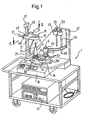
- Fig. 1 shows a unit transportable shrinking device 1 for tool holder 3 of rotating tools 5, such as drills or Cutters. Such tool holders have such.
- B. Fig. 21 shows a Connection shaft 7, for example in the form of a steep cone or a Hohlsteilkegels or the like, with which they are in a machine tool are centrally clamped and the connection shaft 7 axially lying across a tool receiving area 9 with a centric, essentially cylindrical receiving opening 11 for the shaft 13 of the Tool 5.
- the inner diameter of the receiving opening 11 is in one Clamping area 12 of the tool holder 3 is slightly smaller than the outer diameter of the stem 13, with the result that the receiving area 9 of the Tool holder 3 must be heated before moving due to the Thermal expansion of the shaft 13 of the tool 5 in the clamping region 12 of Insert receiving opening 11. After cooling the receiving area 9, the shaft 13 is then press-fitted in the tool holder Third
- the shrinking apparatus 1 (Fig. 1) is in the position of the receiving area 9 of the Tool holder 3 within a few seconds (eg 10 seconds) sufficiently, for example Temperatures of 300 ° C to heat and subsequently in turn comparably short time (eg 30 seconds) to ambient temperature cool.
- the shrinking device 1 has a Induction spinner unit 15, which via a flexible cable 17 from a Indu Vietnamesesstromgenerator 18 is fed.
- the induction current generator 18 generates alternating currents or in the illustrated embodiment pulsed direct currents with a preferably changeable frequency between 50 Hz and a few kHz, such as. B. 20 kHz, which, when the induction coil unit 15 with the interior 19 of her following even closer explained induction coil 21 is substantially centrally on the receiving area 9 of the tool holder 3 is placed eddy currents in the Metal body of the tool holder 3 induced and this inductive Way warmed up.
- the induction current generator 18 may be conventional be constructed and, for example, one of a DC link powered, adjustable in its performance and its frequency Include frequency inverters.
- the tool holder 3 is seated with a vertical axis and upwardly directed receiving opening 11 in a receptacle or Opening a receiving body 23 on a subsequent closer explained, about a vertical axis rotatable turntable 24 and in axial alignment of the induction coil 21 of the induction coil unit 15, the in turn guided manually displaceable on a vertical guide column 25 is.
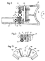
- the induction coil unit 15 comprises, as also shown in FIG. 2, a Handling handle 27, on the one hand the handling of the induction coil unit 15 facilitated during the vertical adjustment and on the other hand, an idling operation automatically clamped Reibarretiervorides the induction coil unit 15 is able to unlock.
- Handling handle 27 is for this purpose on a pin 31 about a transversely to Guide pillar 25 extending pivot axis tiltably fixed and is of a supported on the induction coil unit 15 spring 33 against the with the handling handle 27 overlapping guide column 25 biased. In the overlapping area, the handling handle 27 carries a friction element 35. If the handling handle 27 against the bias of the spring 33rd tilted, the friction element 35 lifts off from the guide column 25 and the Induction coil unit 15 can be moved along the guide column 25 become.
- the handling handle 27 allows in one-handed operation both the Shift operation of the induction coil unit 15 and the release of the Pin Retaining Device 29.
- a spring motor 37 (FIG. 1) arranged, a non-illustrated cable winding drum with a along the guide column 25 to the induction coil unit 15 guided rope in the winding direction drives.
- the spring motor 37 compensates at least partially the weight of the induction coil unit 15th
- the induction coil unit 15 operationally removable held on the guide column 25, so that the Induction current generator 18 with different induction coil units 15 can be connected.
- the handling handle 27 inclusive the Klemmarret istaires 29 are for this purpose on a longitudinal the guide column 25 mounted on a ball bearing slidable carriage 41, the induction coil unit 15 by means of a transverse to the guide rail 25 extending dovetail guide rail 43 slidably fixed.
- the tool holder 3 is in the receiving body 23 of the turntable 24 is inserted, and the induction coil unit 15 lowered from the raised position shown in Fig. 1, until the induction coil 21 encloses the receiving region 9.
- Tastschalters 46 becomes the induction current supply of the induction coil 21 turned on, which by a likewise on the induction coil unit 15th arranged indicator lamp 48 for the duty cycle of the current displayed becomes.
- the induction current flows during the freely selectable operating time of the switch 46.
- the induction current generator 18 switches the Power only after a predetermined safety period from, to unintentional premature damage to the tool or tool holder to prevent.
- the operator of the shrinking device 1 actuates the button 46 only so long until the tool 5 either by itself or with less manual tuition in the vertically aligned receiving opening 11 of the Tool holder 3 sinks. Immediately thereafter, the induction current be switched off and unnecessary heating of the tool holder. 3 be avoided.
- the receiving body 23rd In turn arranged on the turntable .24 and is together with this and the seated in the receiving body 23 tool holder 3 in moves a position in which a flexible hoses 50 with Coolant from a cooling unit 51 fed cooling sleeve 53 the receiving area 9 of the tool holder 3 placed flush against surface becomes.
- the planar contact of the inner jacket of the cooling sleeve 53rd on the outer surface of the receiving area 9 of the tool holder 3 and the Cooling of the cooling sleeve 53 by in a closed circuit through the cooling sleeve 53 and the cooling unit 51 circulating Coolant ensure very rapid cooling of the tool holder 3 Ambient temperature.
- the turntable 24 with Direction of rotation dependent effective detents provided the rotation only allow in the direction indicated by an arrow 54 direction of rotation, in which the tool holder 3 from the operator side of the shrinking device 1 away from the heating position below the induction coil unit 15 in the Placing the cooling sleeve 53 certain position is moved.
- the turntable 24 carries, as shown in FIG. 1, distributed on its circumference more as two, here three receiving body 23, and also the cooling unit 51st feeds several cooling sleeves 53 at the same time. That way you can several tool holders are cooled simultaneously without the Inductive heating of the tool holder would be hindered by this.
- the Kühtmanschetten 53 have eyelets 55, with which they can be removed on a Holding wall 57 of the shrinking device 1 are suspended.
- slots 59 are also provided, in which the cooling liquid hoses 50 of the cooling sleeves 53 longitudinally displaceable and be managed in an orderly manner.
- the cooling boots 53 may have different inner diameter and have different inner shape, depending on the one to be cooled Tool holders 3; but they can also have the same dimensions, if only one and the same type of tool holder should be shrunk.
- the receiving body 23 can be removed on the turntable 24 be held. In the illustrated embodiment, the three receiving body 23 attached to a common hub 61 with play, so that the group of these receiving body 23 are exchanged as a unit can.
- the game of hub attachment prevents jamming of the receiving body 23 in for receiving the receiving body 23 to the Turntable 24 provided centering 63rd
- the cooling unit 51 is preferably an after Heat pump prip working aggregate, albeit other Cooling units are suitable.
- the individual cooling sleeves 53 can connected in parallel to the cooling unit and optionally individually switched on and off. In the illustrated embodiment are the cooling units are connected in series in a common cooling circuit and regardless of whether they are in use or not, by the Coolant cooled.
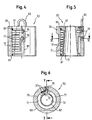
- the cooling sleeve 53 comprises two coaxially arranged sleeve members 67, 69, of which the outer sleeve member 69 as a comparative thick-walled and thus mechanically stable, annularly closed Cylinder tube section is formed and a circular cylindrical inner circumferential surface 71 has.
- the inner sleeve member 67 has in its tube wall a both axially and radially continuous slot 73 and lies with his circular cylindrical outer peripheral surface 75 on the inner circumferential surface 71st of the outer sleeve member 69 at.
- the inner lateral surface 72 of the inner Sleeve member 67 is in its opening width and in its cone angle the corresponding dimensions of the clamping or receiving area to be cooled 9 of the tool holder 3 closely matched, so that the inner Sleeve member 67 when placed on the tool holder 3 cooling sleeve 53 in the largest possible direct investment contact stands for the tool holder 3.
- the wall of the inner Sleeve member 67 has a both radially and axially continuous, axially extending slot 73.
- the outer jacket 75 of the inner sleeve member 67 does not contain overlapping with the slot 73 a meandering groove 77, the at the outer sleeve member 69 passing through port openings 79th for the cooling hoses 50 (Fig. 1) ends.
- the groove 77 forms together with the inner shell 71 of the outer sleeve member 69 a cooling fluid channel within the cooling sleeve 53.
- the covered by the groove 77 Area of the outer circumferential surface 75 of the inner sleeve member 67 is of an annularly closed sealing ring 81 covers, located in Circumferential direction along the axial ends of the inner sleeve member 67th on the one hand and on both sides of the slot 73 extends axially.
- the sealing ring 81 seals the region of the groove 77 to the outside, in such a way that the inner sleeve member 67 still to some extent radially for the Compensation of dimensional tolerances of the conical inner surface 72 can deform relative to the tool holder 3.
- the radial and axial dimensions of the groove cross-section are greater than that Material areas between adjacent portions of the groove 77 on the one hand and the radial thickness of the sleeve cross-section in the region of the groove bottoms.
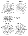
- outer sleeve member 69 of the embodiment of FIG. 4 to 6 circular cylindrical shape and is not slotted, is the outer sleeve member 69a of the cooling sleeve 53a shown in FIGS. 7 to 9 as Konus sleeve formed, and accordingly has the inner sleeve member 67a a conical outer jacket 75a.
- the inner sleeve element 67a in turn has an axially and radially continuous, axially extending slot 73a. Escaping with this slot 73a is also the outer sleeve member 69a with an axially and radially continuous slot 83, which, together with the slot 73 a, a strain compensation the cooling sleeve 53a allows.
- bias springs 84 which the slot edges to bias one another.
- the biasing springs 84 can with their Ends to be attached to the outer sleeve member 69 a; the feathers but can also be closed as a ring, the sleeve member 69 a be formed enclosing ring springs.
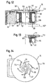
- FIG. 10 1 and 1 show a variant of a cooling sleeve 53b, which consists of several here four, each completed and each for a cooling channel section forming cuff segments 85 is constructed.
- Each of the Cuff segments 85 consists of one in the circumferential direction End walls 87 limited inner sleeve segment 67 b and an outer sleeve segment 69 b, the inner jacket 71 b the Outer jacket 75b of the inner sleeve segment 67b is adapted.
- Each of the sleeve segments 85 is in this case by itself a sealing ring 81 b sealed, as preceded by the sealing ring 81 was explained.
- the outer sleeve segments 69b formed as sections of a circular cylindrical tube and the inner Sleeve segment 67b accordingly has a circular cylinder section-shaped Outside contour, while the inner shell 72b of the outer contour of the Tool holder is adapted and, for example, has cone shape. It It should be understood that also the outer sleeve segment 69b is cone-shaped may be designed, as shown in Fig. 7.
- the sleeve segments 85 are on axially both sides of the cooling sleeve 53b by a respective annular spring 91, the end-side projections of the inner Sleeve segments 67b encloses, radially elastically held together.
- the Annular spring 91 may optionally also on the outer sleeve segments 69b be held.
- the ring springs 91 sit here at least their half spiral diameter with little play in each other in the circumferential direction aligned grooves 92 of the approaches and at the same time provide for the axial alignment and fixation of the sleeve segments 85 to each other.
- FIGS. 12 to 15 show details of the induction coil unit 15.
- the Induction coil unit 15 carries in a circular cylindrical receiving opening 93 of an existing non-magnetic material body 95 wound on a bobbin 97 wire winding 99 of the Induction coil 21.
- inductively heated Tool holder is on the outside of the winding 99, a yoke assembly 101 of ferromagnetic material, such as ferrite arranged.
- the Yoke assembly 101 has a sleeve-shaped outer circumference of the winding 99 enclosing, possibly from a plurality of spaced apart arranged plates arranged axial yoke element 103, to which radially over the axial ends of the winding 99 cross-yoke elements 105th connect.
- the yoke elements 105 can as annular disks or also as spaced apart segment plates be educated.
- the inner diameter of the opening 19 is for the maximum diameter designed to be heated tool holder.
- To be synonymous with comparatively large radial distance of the winding 99 from the tool holder To obtain sufficiently large induction currents sits at least one axial end of the winding 99 a over the inner circumference of the winding 99th in the opening 19 radially projecting Polschuhan onion 107 with variable, the outer diameter of the tool holder operational selectable customizable inside diameter.
- the pole piece arrangement 107 has a plurality distributed in the circumferential direction of the winding 99, and themselves preferably also in the circumferential direction overlapping yoke elements 109th of ferromagnetic material, for example ferrite material, each for themselves fixedly fixed in the base body 95, radial pin 111 (FIG.
- a Polschuhan onion 107 of the type explained is arranged, since this pole piece arrangement then in overlap with the Front side of the tool holder can be brought.
- 107 ' is a further Polschuhan extract on the underside of the induction coil 21st indicated, which optionally additionally or alternatively to the pole piece 107 may be provided.
- the radial yoke elements 105 also omitted.
- the yoke elements are radial slidably guided on the main body of the induction coil unit.
- the 16 to 18 show a variant in which a plurality of circular disk-shaped Yoke elements 109c on parallel to the coil axis extending pin 119 eccentrically to its disk center pivotally mounted on the main body 95th are stored.
- the yoke elements 109c also form a variable here Pole shoe arrangement 107c, which is centered by means of a coil axis rotatable control disk 113c together in the opening 19 of the induction coil unit be swung in or swung out of this can.
- the controls 109c have this again centric Cam follower pin 1 17c, in oblique to the circumferential direction of the control disc 113c extending slots 115c are guided.
- Fig. 16 shows this the yoke elements 109c in their coil axis remote position, while Fig. 17 shows the coil axis-near position.
- FIGS. 19 and 20 show a variant in which the Yoke elements have elongate shape and at their the induction coil axis far end by means of pivot pin 119d in the end plane of the Induction coil 21 are pivotally mounted. Also the yoke elements 109d carry cam follower pins 117d, which in oblique to the circumferential direction extending slots 1 15d a common control disc engage.
- FIG. Fig. 19 shows the yoke elements 109d in their position remote from the spool axis; Fig. 20 shows the coil axis near position of the yoke elements.
Landscapes
- Physics & Mathematics (AREA)
- Electromagnetism (AREA)
- Engineering & Computer Science (AREA)
- Mechanical Engineering (AREA)
- General Induction Heating (AREA)
- Gripping On Spindles (AREA)
- Cutting Tools, Boring Holders, And Turrets (AREA)
- Jigs For Machine Tools (AREA)
- Lubricants (AREA)
- Disintegrating Or Milling (AREA)
Priority Applications (4)
| Application Number | Priority Date | Filing Date | Title |
|---|---|---|---|
| EP04029249A EP1519632B1 (de) | 2000-05-22 | 2000-05-22 | Schrumpfvorrichtung für einen Werkzeughalter |
| EP04029248A EP1518624B1 (de) | 2000-05-22 | 2000-05-22 | Schrumpfvorrichtung für einen Werkzeughalter |
| AT04029248T ATE480354T1 (de) | 2000-05-22 | 2000-05-22 | Schrumpfvorrichtung für einen werkzeughalter |
| AT04029249T ATE445307T1 (de) | 2000-05-22 | 2000-05-22 | Schrumpfvorrichtung für einen werkzeughalter |
Applications Claiming Priority (1)
| Application Number | Priority Date | Filing Date | Title |
|---|---|---|---|
| PCT/EP2000/004645 WO2001089758A1 (de) | 2000-05-22 | 2000-05-22 | Schrumpfvorrichtung für einen werkzeughalter |
Related Child Applications (4)
| Application Number | Title | Priority Date | Filing Date |
|---|---|---|---|
| EP04029248A Division EP1518624B1 (de) | 2000-05-22 | 2000-05-22 | Schrumpfvorrichtung für einen Werkzeughalter |
| EP04029249A Division EP1519632B1 (de) | 2000-05-22 | 2000-05-22 | Schrumpfvorrichtung für einen Werkzeughalter |
| EP04029248.4 Division-Into | 2004-12-09 | ||
| EP04029249.2 Division-Into | 2004-12-09 |
Publications (2)
| Publication Number | Publication Date |
|---|---|
| EP1283759A1 EP1283759A1 (de) | 2003-02-19 |
| EP1283759B1 true EP1283759B1 (de) | 2005-10-26 |
Family
ID=8163954
Family Applications (3)
| Application Number | Title | Priority Date | Filing Date |
|---|---|---|---|
| EP00935096A Expired - Lifetime EP1283759B1 (de) | 2000-05-22 | 2000-05-22 | Schrumpfvorrichtung für einen werkzeughalter |
| EP04029249A Expired - Lifetime EP1519632B1 (de) | 2000-05-22 | 2000-05-22 | Schrumpfvorrichtung für einen Werkzeughalter |
| EP04029248A Expired - Lifetime EP1518624B1 (de) | 2000-05-22 | 2000-05-22 | Schrumpfvorrichtung für einen Werkzeughalter |
Family Applications After (2)
| Application Number | Title | Priority Date | Filing Date |
|---|---|---|---|
| EP04029249A Expired - Lifetime EP1519632B1 (de) | 2000-05-22 | 2000-05-22 | Schrumpfvorrichtung für einen Werkzeughalter |
| EP04029248A Expired - Lifetime EP1518624B1 (de) | 2000-05-22 | 2000-05-22 | Schrumpfvorrichtung für einen Werkzeughalter |
Country Status (8)
| Country | Link |
|---|---|
| US (3) | US6861625B1 (enExample) |
| EP (3) | EP1283759B1 (enExample) |
| JP (1) | JP4660052B2 (enExample) |
| AT (3) | ATE307697T1 (enExample) |
| AU (1) | AU2000250703A1 (enExample) |
| DE (3) | DE50015759D1 (enExample) |
| ES (2) | ES2349772T3 (enExample) |
| WO (1) | WO2001089758A1 (enExample) |
Cited By (2)
| Publication number | Priority date | Publication date | Assignee | Title |
|---|---|---|---|---|
| DE102009022878A1 (de) * | 2009-05-27 | 2011-02-10 | Kamm, Manfred | Mittels der Anwendung von Induktionserwärmung Entfernung von Ventilsitzring aus Zylinderkopf |
| EP3691410A1 (de) * | 2015-12-28 | 2020-08-05 | Haimer GmbH | Schrumpfgerät für den vorzugsweise mobilen einsatz |
Families Citing this family (67)
| Publication number | Priority date | Publication date | Assignee | Title |
|---|---|---|---|---|
| DE19915412B4 (de) | 1999-04-06 | 2007-09-20 | Innovat Gesellschaft für Sondermaschinenbau, Meß- und Steuerungstechnik mbH | Vorrichtung zum Spannen von Werkzeugen |
| DE10015074C1 (de) * | 2000-03-25 | 2001-08-16 | Glimpel Emuge Werk | Schrumpfgerät für Werkzeuge,insbesondere Hartmetallwerkzeuge |
| US6755228B2 (en) * | 2000-05-22 | 2004-06-29 | Kelch Gmbh & Co. Werkzeugmaschinenfabrik | Method and apparatus for the thermal clamping and releasing of tools |
| WO2001089758A1 (de) * | 2000-05-22 | 2001-11-29 | Franz Haimer Gmbh | Schrumpfvorrichtung für einen werkzeughalter |
| JP2003071670A (ja) * | 2001-09-03 | 2003-03-12 | Showa Seimitsu Koki Kk | シュリンク式ツールホルダ用クーリングユニット |
| DE10222092B4 (de) | 2001-11-12 | 2015-02-12 | Franz Haimer Maschinenbau Kg | Schrumpfvorrichtung für einen Werkzeughalter |
| DE20203783U1 (de) | 2002-03-08 | 2003-07-17 | Franz Haimer Maschinenbau KG, 86568 Hollenbach | Voreinstellvorrichtung für einen Schrumpf-Werkzeughalter |
| FR2840841B1 (fr) * | 2002-04-04 | 2005-12-30 | Fournel | Procede de refroidissement de porte-outils a fretter |
| DE10233917A1 (de) | 2002-07-25 | 2004-02-12 | Franz Haimer Maschinenbau Kg | Unwucht-Messvorrichtung |
| FR2844734B1 (fr) * | 2002-09-24 | 2005-01-21 | Fournel | Procede de refroidissement de porte-outils par air |
| DE10249072A1 (de) * | 2002-10-21 | 2004-06-09 | E. Zoller GmbH & Co. KG Einstell- und Messgeräte | Verfahren zum Befestigen eines Werkzeugs in einem Werkzeugfutter |
| DE10255362B3 (de) * | 2002-11-27 | 2004-03-18 | Franz Haimer Maschinenbau Kg | Induktionsanordnung zum induktiven Erwärmen eines Werkzeughalters |
| DE10309015A1 (de) * | 2003-03-01 | 2004-09-16 | Wagner-Werkzeugsysteme Müller GmbH | Werkzeugschrumpfaufnahme |
| US7143490B2 (en) * | 2003-03-12 | 2006-12-05 | Kennametal Inc. | Tap process for hard workpieces |
| DE10317576B4 (de) * | 2003-04-16 | 2017-03-09 | Franz Haimer Maschinenbau Kg | Vorrichtung zum Einspannen eines Rotationswerkzeugs in einen Werkzeughalter |
| DE102004019867A1 (de) * | 2004-04-23 | 2005-11-17 | Franz Haimer Maschinenbau Kg | Dämpfungsadapter für ein induktives Schrumpfgerät |
| DE102004042770A1 (de) * | 2004-06-14 | 2005-12-29 | Franz Haimer Maschinenbau Kg | Werkzeughalter für ein Rotationswerkzeug |
| DE202004013916U1 (de) | 2004-09-07 | 2006-01-12 | Haimer Gmbh | Gerät zum Spannen eines Rotationswerkzeugs in einem Werkzeughalter |
| DE102005005892A1 (de) * | 2005-02-09 | 2006-08-10 | Haimer Gmbh | Induktionsspuleneinheit |
| DE102005014984A1 (de) | 2005-04-01 | 2006-10-05 | Franz Haimer Maschinenbau Kg | Induktionsspulen-Baueinheit |
| DE102005038582B4 (de) * | 2005-08-16 | 2007-09-13 | Esa Eppinger Gmbh | Werkzeugspanneinsatz und Werkzeugspanneinrichtung |
| DE102005057476B3 (de) * | 2005-11-30 | 2007-08-02 | Haimer Gmbh | Schrumpfvorrichtung mit Kühlvorrichtung, Kühlvorrichtung für eine Schrumpfvorrichtung, Kühlerschaltvorrichtung, Verfahren zur Montage einer Kühlerschaltvorrichtung |
| US7367763B2 (en) * | 2005-12-15 | 2008-05-06 | Kennametal Inc. | Shrink fit tool holder with grooves |
| DE102006028408A1 (de) | 2006-04-10 | 2007-10-31 | Franz Haimer Maschinenbau Kg | Auszugssicherung von Werkzeugen aus Werkzeughaltern mit einer Werkzeugaufnahme |
| ES2425590T3 (es) * | 2007-02-16 | 2013-10-16 | Franz Haimer Maschinenbau Kg | Dispositivo de contracción de campo transversal con medios para limitar pérdidas de flujo magnético |
| DE202011109498U1 (de) | 2011-12-27 | 2012-02-13 | Franz Haimer Maschinenbau Kg | Werkzeughalter und Spannsystem mit einem derartigen Werkzeughalter |
| DE202007019480U1 (de) | 2007-04-05 | 2012-11-09 | Franz Haimer Maschinenbau Kg | Auszugssicherung von Werkzeugen aus Werkzeughaltern mit einer Werkzeugaufnahme |
| DE202007007837U1 (de) * | 2007-06-01 | 2007-09-27 | Franz Haimer Maschinenbau Kg | Schrumpfspule mit direkter Werkzeugkühlung |
| DE102007054782A1 (de) * | 2007-11-16 | 2009-05-20 | Mtu Aero Engines Gmbh | Induktionsspule, Verfahren und Vorrichtung zur induktiven Erwärmung von metallischen Bauelementen |
| DE102007059812A1 (de) * | 2007-12-11 | 2009-06-18 | Multivac Sepp Haggenmüller Gmbh & Co. Kg | Verpackungsmaschine mit Induktionsheizung |
| DE102008045781A1 (de) | 2008-09-04 | 2010-03-11 | Franz Haimer Maschinenbau Kg | Induktive Spannvorrichtung für das Ein- und Ausspannen von Werkzeugen |
| DE102008062255A1 (de) | 2008-12-15 | 2010-06-17 | Franz Haimer Maschinenbau Kg | Wuchtvorrichtung mit Zusatzlager |
| DE102009034730A1 (de) | 2009-07-24 | 2011-01-27 | Franz Haimer Maschinenbau Kg | Nebelkühlung |
| DE102009053615B3 (de) * | 2009-10-02 | 2011-03-17 | Fahrion, Ulrich | Verfahren und Vorrichtung zur Einrichtung eines Werkzeughalters |
| JP5172914B2 (ja) * | 2010-09-06 | 2013-03-27 | ハイマー・ゲーエムベーハー | 工具保持具用焼きばめ装置 |
| DE102011082613B4 (de) | 2011-09-13 | 2024-08-14 | Haimer Gmbh | Induktionsspuleneinheit |
| DE102012002596A1 (de) * | 2012-02-13 | 2013-08-14 | Franz Haimer Maschinenbau Kg | Vorrichtung zur Kühlung eines Schrumpffutters |
| CN102909521B (zh) * | 2012-10-17 | 2015-12-16 | 哈尔滨工程大学 | 一种行星齿轮箱单层行星轴压装装置 |
| US20140175761A1 (en) * | 2012-12-21 | 2014-06-26 | Chin-Chiu Chen | Sleeve for heating a toolholder |
| JP6113498B2 (ja) * | 2012-12-27 | 2017-04-12 | 東芝機械株式会社 | 焼嵌めホルダ用自動工具交換システム |
| US9302330B2 (en) * | 2013-12-03 | 2016-04-05 | Ching-Ting Chen | Adjustable heating mantle for a tool holder |
| CN103737245B (zh) * | 2014-01-15 | 2017-05-24 | 中汽成都配件有限公司 | 轴类零件热套过程中的冷却装置 |
| JP2015174181A (ja) * | 2014-03-14 | 2015-10-05 | 牧野フライス精機株式会社 | 工作機械の固定部材 |
| JP6268022B2 (ja) * | 2014-03-28 | 2018-01-24 | Dmg森精機株式会社 | 工作機械の主軸装置 |
| CN104084755B (zh) * | 2014-06-30 | 2017-09-22 | 日立电梯电机(广州)有限公司 | 自动热套装置及其控制方法 |
| US10281311B2 (en) | 2014-09-11 | 2019-05-07 | Dresser, Llc | Method of operating a liquid-level transmitter device and implementation thereof |
| CN104400241B (zh) * | 2014-11-25 | 2016-04-13 | 绵阳市雅森五金工具有限公司 | 一种实用的钻头加工装置 |
| CN104475907B (zh) * | 2014-11-25 | 2016-04-13 | 绵阳市雅森五金工具有限公司 | 一种用于钻头加工的装置 |
| CN104493423A (zh) * | 2014-12-04 | 2015-04-08 | 东莞市思诚机电科技有限公司 | 刀柄加热器及其操作方法 |
| DE202015006540U1 (de) | 2015-09-16 | 2015-12-14 | Franz Haimer Maschinenbau Kg | Schrumpfgerät |
| DE102015016831A1 (de) | 2015-12-28 | 2017-06-29 | Haimer Gmbh | Schrumpfgerät mit Heizkontrolle |
| CN106271710A (zh) * | 2016-08-26 | 2017-01-04 | 上海小糸车灯有限公司 | 一种用于热烫刀具的装夹定位装置 |
| DE102017115202A1 (de) * | 2017-07-07 | 2019-01-10 | Bilz Werkzeugfabrik Gmbh & Co. Kg | Vorrichtung zum induktiven Erwärmen eines Bauteils |
| TWI674937B (zh) * | 2019-01-18 | 2019-10-21 | 興源機械工業股份有限公司 | 具可調整之加熱罩阻隔結構的刀桿加熱機 |
| CN109986366B (zh) * | 2019-03-11 | 2024-02-23 | 成都成林数控刀具股份有限公司 | 一种刀具热装冷却机构及热装机 |
| DE102019108904A1 (de) * | 2019-04-04 | 2020-10-08 | E. Zoller GmbH & Co. KG Einstell- und Messgeräte | Ein- und/oder Ausschrumpfspannstation für Werkzeuge und Verfahren mit einer Ein- und/oder Ausschrumpfspannstation für Werkzeuge |
| DE102019124428A1 (de) | 2019-09-11 | 2021-03-11 | Franz Haimer Maschinenbau Kg | Vorrichtung zur, insbesondere automatisierten, Bereitstellung eines Komplettwerkzeugs |
| EP3840534B1 (de) * | 2019-12-20 | 2024-03-06 | E. Zoller GmbH & Co. KG Einstell- und Messgeräte | Induktionsheizvorrichtung, ein- und/oder ausschrumpfspannstation und verfahren |
| DE102020129700A1 (de) * | 2019-12-20 | 2021-06-24 | E. Zoller GmbH & Co. KG Einstell- und Messgeräte | Induktionsheizvorrichtung, Ein- und/oder Ausschrumpfspannstation und Verfahren |
| CN111438540B (zh) * | 2020-04-29 | 2024-07-05 | 苏州智润精工科技有限公司 | 一种狭缝节流气浮转台 |
| DE102020118997A1 (de) | 2020-06-09 | 2021-12-09 | E. Zoller GmbH & Co. KG Einstell- und Messgeräte | Schrumpfspannabkühlvorrichtung und Werkzeug-Schrumpfspannverfahren |
| EP3922401A1 (de) * | 2020-06-09 | 2021-12-15 | E. Zoller GmbH & Co. KG Einstell- und Messgeräte | Schrumpfspannabkühlvorrichtung und werkzeug-schrumpfspannverfahren |
| CN111791178A (zh) * | 2020-07-20 | 2020-10-20 | 珠海格力智能装备有限公司 | 辅助安装装置 |
| DE102022120248B4 (de) | 2022-08-11 | 2024-06-06 | INNOVAT GmbH | Vorrichtung zur Induktionserwärmung eines Werkzeughalters |
| CN115922313A (zh) | 2022-11-30 | 2023-04-07 | 立讯电子科技(昆山)有限公司 | 一种密封圈自动组装装置 |
| CN117381120B (zh) * | 2023-11-29 | 2025-12-02 | 浙江宇盛工具有限公司 | 一种t型指接刀用刀片焊接装置 |
| CN117943779B (zh) * | 2024-03-21 | 2024-06-14 | 苏州大学 | 一种金属与玻璃一次性焊接的辅助夹具 |
Family Cites Families (38)
| Publication number | Priority date | Publication date | Assignee | Title |
|---|---|---|---|---|
| US2643325A (en) * | 1950-10-06 | 1953-06-23 | Ohio Crankshaft Co | Progressive high-frequency heating of variable-dimension shafts |
| DE922700C (de) * | 1952-06-20 | 1955-01-20 | Skf Kugellagerfabriken Gmbh | Vorrichtung fuer das Fuegen und Loesen von Pressverbaenden, insbesondere von auf Wellen festsitzenden ringfoermigen Koerpern, z. B. Innenringen von Waelzlagern |
| FR1524221A (fr) * | 1967-03-21 | 1968-05-10 | Procedes De Boites D Essieux I | Appareil de chauffage par induction d'une bague métallique |
| US3935416A (en) * | 1974-06-24 | 1976-01-27 | Park-Ohio Industries, Inc. | Inductor-workpiece position detector |
| EP0027828B1 (de) * | 1979-10-24 | 1984-03-21 | Maschinenfabrik Alfing Kessler GmbH | Induktor zum Aufheizen von rotierenden metallenen Werkstücken, insbesondere Kurbelwellen, zum Zweck der Oberflächenhärtung mit unterschiedlichen Einwirktiefen |
| SU903066A1 (ru) | 1980-06-18 | 1982-02-07 | Украинский Заочный Политехнический Институт | Переносное устройство дл разборки прессовых соединений |
| US4580616A (en) | 1982-12-06 | 1986-04-08 | Techmet Corporation | Method and apparatus for controlled solidification of metals |
| US4625090A (en) * | 1984-05-30 | 1986-11-25 | Park-Ohio Industries, Inc. | Apparatus for inductively heat treating workpiece bore walls |
| JPS6261722A (ja) * | 1985-09-10 | 1987-03-18 | Kawasaki Heavy Ind Ltd | 二重管製造方法 |
| SU1362605A1 (ru) | 1986-05-13 | 1987-12-30 | Украинский заочный политехнический институт им.И.З.Соколова | Индукционное устройство дл разборки прессовых соединений |
| SU1556861A1 (ru) | 1988-07-20 | 1990-04-15 | Украинский заочный политехнический институт им.И.З.Соколова | Установка дл тепловой разборки прессовых соединений |
| DE69101976T2 (de) | 1990-01-08 | 1994-09-01 | Mori Seiki Seisakusho Kk | Spindel-Einheit für Werkzeugmaschine. |
| JP2912401B2 (ja) * | 1990-01-08 | 1999-06-28 | 株式会社森精機製作所 | 工具のクランプ装置 |
| JPH0741476B2 (ja) * | 1990-01-11 | 1995-05-10 | 川崎重工業株式会社 | 複重管分離方法 |
| JPH03275574A (ja) * | 1990-03-22 | 1991-12-06 | Mitsubishi Heavy Ind Ltd | セラミックス部材と金属部材との結合法 |
| US5127780A (en) * | 1990-09-20 | 1992-07-07 | Kennametal Inc. | Expandable holding device using a fusible alloy |
| US5140666A (en) * | 1990-11-16 | 1992-08-18 | Lamb James E | Heating apparatus for expanding a cylindrical wall using heated air |
| FR2693072B1 (fr) * | 1992-06-24 | 1994-09-02 | Celes | Perfectionnements apportés aux bobines de système de chauffage par induction. |
| JPH0631570A (ja) * | 1992-07-22 | 1994-02-08 | Osaka Kiko Co Ltd | 工具交換装置 |
| US5311654A (en) * | 1992-09-25 | 1994-05-17 | Cook Harold D | Tool holder system and method of making |
| DE4415091C1 (de) * | 1994-04-29 | 1996-01-18 | Fritz Dr Feldmeier | Verfahren und Vorrichtung zum kontinuierlichen, spanlosen profilierenden Zerteilen von rohrförmigen Werkstücken in einzelne, untereinander gleiche Ringe |
| FR2720503B1 (fr) * | 1994-05-26 | 1996-06-21 | Commissariat Energie Atomique | Système de caractérisation thermomécanique de matériaux utilisant un dispositif de chauffage rapide par induction. |
| JPH08247143A (ja) * | 1995-03-08 | 1996-09-24 | Toyota Motor Corp | 位置決めガイド |
| JP3437322B2 (ja) * | 1995-04-07 | 2003-08-18 | 富士通株式会社 | 半導体集積装置 |
| US5935476A (en) * | 1996-01-16 | 1999-08-10 | Linlan Induction Ab | Device for heating a press tool using magnetic induction heating; press having such a device, and method of manufacture |
| FR2745437A1 (fr) * | 1996-02-28 | 1997-08-29 | Leroy Somer Moteurs | Carter de refroidissement pour appareil electrique, une machine tournante comportant un tel carter, ainsi que le procede de fabrication d'un tel carter |
| DE19638822A1 (de) * | 1996-09-20 | 1998-03-26 | Fx Marquart Gmbh | Spanneinrichtung zur Befestigung eines Werkzeuges an einer Werkzeugmaschine sowie Vorrichtung zum Spannen von Werkzeugen im Schrumpfsitz |
| DE29705185U1 (de) * | 1997-03-21 | 1997-06-19 | Hauser, Hermann, 79331 Teningen | Vorrichtung zum Aufheizen eines Werkzeughalters |
| JPH1153225A (ja) * | 1997-07-31 | 1999-02-26 | Hitachi Ltd | 障害処理装置 |
| FR2768071B1 (fr) * | 1997-09-05 | 1999-11-12 | E P B Emile Pfalzgraf | Dispositif pour l'assemblage et le desassemblage d'un outil avec un porte-outils |
| JPH1177443A (ja) * | 1997-09-09 | 1999-03-23 | Mst Corp | 焼きばめ装置及び該装置で使用される刃物挿入規制具 |
| DE19844018A1 (de) | 1998-09-25 | 2000-03-30 | G H Induction Deutschland Indu | Verfahren und Vorrichtung zum Schrumpfspannen von Werkzeugen |
| US6048144A (en) * | 1998-10-26 | 2000-04-11 | Bohler; Lloyd C. | Temperature insertion spindle |
| DE29820838U1 (de) * | 1998-11-21 | 1999-04-22 | Helmut Diebold GmbH & Co. Goldring-Werkzeugfabrik, 72417 Jungingen | Reduzierhülse für eine Schrumpfvorrichtung für eine Werkzeugaufnahme |
| DE10015074C1 (de) * | 2000-03-25 | 2001-08-16 | Glimpel Emuge Werk | Schrumpfgerät für Werkzeuge,insbesondere Hartmetallwerkzeuge |
| US6755228B2 (en) * | 2000-05-22 | 2004-06-29 | Kelch Gmbh & Co. Werkzeugmaschinenfabrik | Method and apparatus for the thermal clamping and releasing of tools |
| WO2001089758A1 (de) * | 2000-05-22 | 2001-11-29 | Franz Haimer Gmbh | Schrumpfvorrichtung für einen werkzeughalter |
| US6400899B1 (en) * | 2000-09-27 | 2002-06-04 | Delphi Technologies, Inc. | Ring assembly manufacturing apparatus and method |
-
2000
- 2000-05-22 WO PCT/EP2000/004645 patent/WO2001089758A1/de not_active Ceased
- 2000-05-22 AT AT00935096T patent/ATE307697T1/de active
- 2000-05-22 AT AT04029248T patent/ATE480354T1/de active
- 2000-05-22 EP EP00935096A patent/EP1283759B1/de not_active Expired - Lifetime
- 2000-05-22 DE DE50015759T patent/DE50015759D1/de not_active Expired - Lifetime
- 2000-05-22 ES ES04029248T patent/ES2349772T3/es not_active Expired - Lifetime
- 2000-05-22 DE DE50011472T patent/DE50011472D1/de not_active Expired - Lifetime
- 2000-05-22 EP EP04029249A patent/EP1519632B1/de not_active Expired - Lifetime
- 2000-05-22 DE DE50015989T patent/DE50015989D1/de not_active Expired - Lifetime
- 2000-05-22 ES ES04029249T patent/ES2332906T3/es not_active Expired - Lifetime
- 2000-05-22 JP JP2001585986A patent/JP4660052B2/ja not_active Expired - Lifetime
- 2000-05-22 AU AU2000250703A patent/AU2000250703A1/en not_active Abandoned
- 2000-05-22 EP EP04029248A patent/EP1518624B1/de not_active Expired - Lifetime
- 2000-05-22 AT AT04029249T patent/ATE445307T1/de active
- 2000-05-22 US US10/275,974 patent/US6861625B1/en not_active Expired - Lifetime
-
2005
- 2005-01-27 US US11/043,070 patent/US7208706B2/en not_active Expired - Fee Related
- 2005-01-27 US US11/043,054 patent/US7115846B2/en not_active Expired - Lifetime
Cited By (3)
| Publication number | Priority date | Publication date | Assignee | Title |
|---|---|---|---|---|
| DE102009022878A1 (de) * | 2009-05-27 | 2011-02-10 | Kamm, Manfred | Mittels der Anwendung von Induktionserwärmung Entfernung von Ventilsitzring aus Zylinderkopf |
| DE102009022878B4 (de) * | 2009-05-27 | 2012-07-05 | Manfred Kamm | Mittels der Anwendung von Induktionserwärmung Entfernung von Ventilsitzring aus Zylinderkopf |
| EP3691410A1 (de) * | 2015-12-28 | 2020-08-05 | Haimer GmbH | Schrumpfgerät für den vorzugsweise mobilen einsatz |
Also Published As
| Publication number | Publication date |
|---|---|
| JP4660052B2 (ja) | 2011-03-30 |
| ES2349772T3 (es) | 2011-01-11 |
| US7115846B2 (en) | 2006-10-03 |
| EP1519632A1 (de) | 2005-03-30 |
| US6861625B1 (en) | 2005-03-01 |
| US7208706B2 (en) | 2007-04-24 |
| EP1518624A1 (de) | 2005-03-30 |
| ES2332906T3 (es) | 2010-02-15 |
| US20050205554A1 (en) | 2005-09-22 |
| WO2001089758A1 (de) | 2001-11-29 |
| ATE307697T1 (de) | 2005-11-15 |
| EP1283759A1 (de) | 2003-02-19 |
| EP1518624B1 (de) | 2010-09-08 |
| DE50015989D1 (de) | 2010-10-21 |
| JP2003534139A (ja) | 2003-11-18 |
| DE50011472D1 (de) | 2005-12-01 |
| ATE445307T1 (de) | 2009-10-15 |
| DE50015759D1 (de) | 2009-11-19 |
| US20050188522A1 (en) | 2005-09-01 |
| ATE480354T1 (de) | 2010-09-15 |
| EP1519632B1 (de) | 2009-10-07 |
| AU2000250703A1 (en) | 2001-12-03 |
Similar Documents
| Publication | Publication Date | Title |
|---|---|---|
| EP1283759B1 (de) | Schrumpfvorrichtung für einen werkzeughalter | |
| EP1847158B1 (de) | Induktionsspuleneinheit | |
| EP1867211B1 (de) | Induktionsspulen-baueinheit | |
| EP1345721B1 (de) | Werkzeughalter für ein um eine drehachse drehbares werkzeug | |
| DE102011082611B4 (de) | Induktionsspuleneinheit | |
| DE202004013916U1 (de) | Gerät zum Spannen eines Rotationswerkzeugs in einem Werkzeughalter | |
| EP1310323A2 (de) | Schrumpfvorrichtung für einen Werkzeughalter | |
| EP2116104B1 (de) | Querfeldschrumpfvorrichtung mit mitteln zur begrenzung von magnetflussverlusten | |
| DE102011082613B4 (de) | Induktionsspuleneinheit | |
| DE10025007B4 (de) | Verfahren und Vorrichtung zum thermischen Spannen und Entspannen von Werkzeugen | |
| DE102005057476B3 (de) | Schrumpfvorrichtung mit Kühlvorrichtung, Kühlvorrichtung für eine Schrumpfvorrichtung, Kühlerschaltvorrichtung, Verfahren zur Montage einer Kühlerschaltvorrichtung | |
| EP1943050A2 (de) | Vorrichtung und verfahren zum lösbaren spannen eines werkzeugs an einer spindelwelle einer werkzeugmaschine | |
| AT502174B1 (de) | Vorrichtung zum induktiven erwärmen eines werkzeughalters | |
| DE102013114643B4 (de) | Heizmantel einer Vorrichtung und Vorrichtung zum Einspannen und/oder Ausspannen von Werkzeugen in/aus Schrumpfspannfutter(n) | |
| DE10025008B4 (de) | Vorrichtung zum thermischen Spannen und Entspannen von Werkzeugen | |
| DE20023809U1 (de) | Vorrichtung zum thermischen Spannen und Entspannen von Werkzeugen | |
| EP1002605B1 (de) | Reduzierhülse für eine Schrumpfvorrichtung für eine Werkzeugaufnahme | |
| DE10222092A1 (de) | Schrumpfvorrichtung für einen Werkzeughalter | |
| DE102013114644B3 (de) | Kühlmantel einer Vorrichtung und Vorrichtung zum Einspannen und/oder Ausspannen von Werkzeugen in/aus Schrumpfspannfutter(n) | |
| EP1804990B1 (de) | Vorrichtung zum induktiven erwärmen eines werkzeughalters | |
| DE102013114645B3 (de) | Vorrichtung zum Einspannen und/oder Ausspannen von Werkzeugen in/aus Schrumpfspannfutter(n), Heiz- und/oder Kühlmantel und Verfahren zum Betreiben einer derartigen Vorrichtung | |
| DE202006002763U1 (de) | Vorrichtung zum lösbaren Spannen eines Werkzeugs an einer Spindelwelle einer Werkzeugmaschine | |
| DE20023453U1 (de) | Vorrichtung zum Spannen von Werkzeugen | |
| DE202006000983U1 (de) | Vorrichtung zum lösbaren Spannen eines Werkzeugs an einer Spindelwelle einer Werkzeugmaschine | |
| DE102006015798A1 (de) | Vorrichtung zum Ein- und Ausspannen eines Werkzeugs |
Legal Events
| Date | Code | Title | Description |
|---|---|---|---|
| PUAI | Public reference made under article 153(3) epc to a published international application that has entered the european phase |
Free format text: ORIGINAL CODE: 0009012 |
|
| 17P | Request for examination filed |
Effective date: 20021113 |
|
| AK | Designated contracting states |
Designated state(s): AT BE CH CY DE DK ES FI FR GB GR IE IT LI LU MC NL PT SE |
|
| AX | Request for extension of the european patent |
Extension state: AL LT LV MK RO SI |
|
| 17Q | First examination report despatched |
Effective date: 20040309 |
|
| GRAP | Despatch of communication of intention to grant a patent |
Free format text: ORIGINAL CODE: EPIDOSNIGR1 |
|
| RAP1 | Party data changed (applicant data changed or rights of an application transferred) |
Owner name: HAIMER GMBH |
|
| GRAS | Grant fee paid |
Free format text: ORIGINAL CODE: EPIDOSNIGR3 |
|
| GRAA | (expected) grant |
Free format text: ORIGINAL CODE: 0009210 |
|
| AK | Designated contracting states |
Kind code of ref document: B1 Designated state(s): AT BE CH CY DE DK ES FI FR GB GR IE IT LI LU MC NL PT SE |
|
| PG25 | Lapsed in a contracting state [announced via postgrant information from national office to epo] |
Ref country code: IE Free format text: LAPSE BECAUSE OF FAILURE TO SUBMIT A TRANSLATION OF THE DESCRIPTION OR TO PAY THE FEE WITHIN THE PRESCRIBED TIME-LIMIT Effective date: 20051026 Ref country code: FI Free format text: LAPSE BECAUSE OF FAILURE TO SUBMIT A TRANSLATION OF THE DESCRIPTION OR TO PAY THE FEE WITHIN THE PRESCRIBED TIME-LIMIT Effective date: 20051026 Ref country code: NL Free format text: LAPSE BECAUSE OF FAILURE TO SUBMIT A TRANSLATION OF THE DESCRIPTION OR TO PAY THE FEE WITHIN THE PRESCRIBED TIME-LIMIT Effective date: 20051026 |
|
| REG | Reference to a national code |
Ref country code: GB Ref legal event code: FG4D Free format text: NOT ENGLISH |
|
| REG | Reference to a national code |
Ref country code: CH Ref legal event code: NV Representative=s name: A. BRAUN, BRAUN, HERITIER, ESCHMANN AG PATENTANWAE Ref country code: CH Ref legal event code: EP |
|
| REG | Reference to a national code |
Ref country code: IE Ref legal event code: FG4D Free format text: LANGUAGE OF EP DOCUMENT: GERMAN |
|
| REF | Corresponds to: |
Ref document number: 50011472 Country of ref document: DE Date of ref document: 20051201 Kind code of ref document: P |
|
| GBT | Gb: translation of ep patent filed (gb section 77(6)(a)/1977) |
Effective date: 20051221 |
|
| PG25 | Lapsed in a contracting state [announced via postgrant information from national office to epo] |
Ref country code: DK Free format text: LAPSE BECAUSE OF FAILURE TO SUBMIT A TRANSLATION OF THE DESCRIPTION OR TO PAY THE FEE WITHIN THE PRESCRIBED TIME-LIMIT Effective date: 20060126 Ref country code: SE Free format text: LAPSE BECAUSE OF FAILURE TO SUBMIT A TRANSLATION OF THE DESCRIPTION OR TO PAY THE FEE WITHIN THE PRESCRIBED TIME-LIMIT Effective date: 20060126 Ref country code: GR Free format text: LAPSE BECAUSE OF FAILURE TO SUBMIT A TRANSLATION OF THE DESCRIPTION OR TO PAY THE FEE WITHIN THE PRESCRIBED TIME-LIMIT Effective date: 20060126 |
|
| PG25 | Lapsed in a contracting state [announced via postgrant information from national office to epo] |
Ref country code: ES Free format text: LAPSE BECAUSE OF FAILURE TO SUBMIT A TRANSLATION OF THE DESCRIPTION OR TO PAY THE FEE WITHIN THE PRESCRIBED TIME-LIMIT Effective date: 20060206 |
|
| PG25 | Lapsed in a contracting state [announced via postgrant information from national office to epo] |
Ref country code: PT Free format text: LAPSE BECAUSE OF FAILURE TO SUBMIT A TRANSLATION OF THE DESCRIPTION OR TO PAY THE FEE WITHIN THE PRESCRIBED TIME-LIMIT Effective date: 20060327 |
|
| NLV1 | Nl: lapsed or annulled due to failure to fulfill the requirements of art. 29p and 29m of the patents act | ||
| REG | Reference to a national code |
Ref country code: IE Ref legal event code: FD4D |
|
| PG25 | Lapsed in a contracting state [announced via postgrant information from national office to epo] |
Ref country code: BE Free format text: LAPSE BECAUSE OF NON-PAYMENT OF DUE FEES Effective date: 20060531 Ref country code: MC Free format text: LAPSE BECAUSE OF NON-PAYMENT OF DUE FEES Effective date: 20060531 |
|
| ET | Fr: translation filed | ||
| PLBE | No opposition filed within time limit |
Free format text: ORIGINAL CODE: 0009261 |
|
| STAA | Information on the status of an ep patent application or granted ep patent |
Free format text: STATUS: NO OPPOSITION FILED WITHIN TIME LIMIT |
|
| 26N | No opposition filed |
Effective date: 20060727 |
|
| BERE | Be: lapsed |
Owner name: HAIMER G.M.B.H. Effective date: 20060531 |
|
| REG | Reference to a national code |
Ref country code: CH Ref legal event code: PFA Owner name: HAIMER GMBH Free format text: HAIMER GMBH#WEIHERSTRASSE 21#86568 HOLLENBACH-IGENHAUSEN (DE) -TRANSFER TO- HAIMER GMBH#WEIHERSTRASSE 21#86568 HOLLENBACH-IGENHAUSEN (DE) |
|
| PG25 | Lapsed in a contracting state [announced via postgrant information from national office to epo] |
Ref country code: LU Free format text: LAPSE BECAUSE OF NON-PAYMENT OF DUE FEES Effective date: 20060522 |
|
| PG25 | Lapsed in a contracting state [announced via postgrant information from national office to epo] |
Ref country code: CY Free format text: LAPSE BECAUSE OF FAILURE TO SUBMIT A TRANSLATION OF THE DESCRIPTION OR TO PAY THE FEE WITHIN THE PRESCRIBED TIME-LIMIT Effective date: 20051026 |
|
| PGFP | Annual fee paid to national office [announced via postgrant information from national office to epo] |
Ref country code: AT Payment date: 20120511 Year of fee payment: 13 |
|
| REG | Reference to a national code |
Ref country code: CH Ref legal event code: PCAR Free format text: NEW ADDRESS: HOLBEINSTRASSE 36-38, 4051 BASEL (CH) |
|
| REG | Reference to a national code |
Ref country code: AT Ref legal event code: MM01 Ref document number: 307697 Country of ref document: AT Kind code of ref document: T Effective date: 20140522 |
|
| PG25 | Lapsed in a contracting state [announced via postgrant information from national office to epo] |
Ref country code: AT Free format text: LAPSE BECAUSE OF NON-PAYMENT OF DUE FEES Effective date: 20140522 |
|
| REG | Reference to a national code |
Ref country code: FR Ref legal event code: PLFP Year of fee payment: 17 |
|
| REG | Reference to a national code |
Ref country code: FR Ref legal event code: PLFP Year of fee payment: 18 |
|
| REG | Reference to a national code |
Ref country code: FR Ref legal event code: PLFP Year of fee payment: 19 |
|
| PGFP | Annual fee paid to national office [announced via postgrant information from national office to epo] |
Ref country code: IT Payment date: 20180423 Year of fee payment: 9 |
|
| PGFP | Annual fee paid to national office [announced via postgrant information from national office to epo] |
Ref country code: GB Payment date: 20180518 Year of fee payment: 19 |
|
| PGFP | Annual fee paid to national office [announced via postgrant information from national office to epo] |
Ref country code: DE Payment date: 20190521 Year of fee payment: 20 |
|
| PGFP | Annual fee paid to national office [announced via postgrant information from national office to epo] |
Ref country code: FR Payment date: 20190522 Year of fee payment: 20 |
|
| PGFP | Annual fee paid to national office [announced via postgrant information from national office to epo] |
Ref country code: CH Payment date: 20190521 Year of fee payment: 20 |
|
| GBPC | Gb: european patent ceased through non-payment of renewal fee |
Effective date: 20190522 |
|
| PG25 | Lapsed in a contracting state [announced via postgrant information from national office to epo] |
Ref country code: IT Free format text: LAPSE BECAUSE OF NON-PAYMENT OF DUE FEES Effective date: 20190522 Ref country code: GB Free format text: LAPSE BECAUSE OF NON-PAYMENT OF DUE FEES Effective date: 20190522 |
|
| REG | Reference to a national code |
Ref country code: DE Ref legal event code: R071 Ref document number: 50011472 Country of ref document: DE |
|
| REG | Reference to a national code |
Ref country code: CH Ref legal event code: PL |