EP1283320A2 - Drehkipp-Beschlag - Google Patents
Drehkipp-Beschlag Download PDFInfo
- Publication number
- EP1283320A2 EP1283320A2 EP02011573A EP02011573A EP1283320A2 EP 1283320 A2 EP1283320 A2 EP 1283320A2 EP 02011573 A EP02011573 A EP 02011573A EP 02011573 A EP02011573 A EP 02011573A EP 1283320 A2 EP1283320 A2 EP 1283320A2
- Authority
- EP
- European Patent Office
- Prior art keywords
- tilt
- fitting according
- bearing
- turn fitting
- turn
- Prior art date
- Legal status (The legal status is an assumption and is not a legal conclusion. Google has not performed a legal analysis and makes no representation as to the accuracy of the status listed.)
- Granted
Links
- 238000003780 insertion Methods 0.000 claims abstract description 24
- 230000037431 insertion Effects 0.000 claims abstract description 24
- 229910052751 metal Inorganic materials 0.000 claims description 5
- 239000002184 metal Substances 0.000 claims description 5
- 229910052782 aluminium Inorganic materials 0.000 claims description 3
- XAGFODPZIPBFFR-UHFFFAOYSA-N aluminium Chemical compound [Al] XAGFODPZIPBFFR-UHFFFAOYSA-N 0.000 claims description 3
- 238000010008 shearing Methods 0.000 abstract 6
- 210000002414 leg Anatomy 0.000 description 23
- 238000010276 construction Methods 0.000 description 2
- 238000000034 method Methods 0.000 description 2
- 229910000639 Spring steel Inorganic materials 0.000 description 1
- 235000013351 cheese Nutrition 0.000 description 1
- 230000006835 compression Effects 0.000 description 1
- 238000007906 compression Methods 0.000 description 1
- 229920001971 elastomer Polymers 0.000 description 1
- 238000009434 installation Methods 0.000 description 1
- 230000002441 reversible effect Effects 0.000 description 1
- 229920002379 silicone rubber Polymers 0.000 description 1
- 239000004945 silicone rubber Substances 0.000 description 1
- 210000000689 upper leg Anatomy 0.000 description 1
Images


Classifications
-
- E—FIXED CONSTRUCTIONS
- E05—LOCKS; KEYS; WINDOW OR DOOR FITTINGS; SAFES
- E05D—HINGES OR SUSPENSION DEVICES FOR DOORS, WINDOWS OR WINGS
- E05D15/00—Suspension arrangements for wings
- E05D15/48—Suspension arrangements for wings allowing alternative movements
- E05D15/52—Suspension arrangements for wings allowing alternative movements for opening about a vertical as well as a horizontal axis
- E05D15/5205—Suspension arrangements for wings allowing alternative movements for opening about a vertical as well as a horizontal axis with horizontally-extending checks
-
- E—FIXED CONSTRUCTIONS
- E05—LOCKS; KEYS; WINDOW OR DOOR FITTINGS; SAFES
- E05D—HINGES OR SUSPENSION DEVICES FOR DOORS, WINDOWS OR WINGS
- E05D7/00—Hinges or pivots of special construction
- E05D7/12—Hinges or pivots of special construction to allow easy detachment of the hinge from the wing or the frame
-
- E—FIXED CONSTRUCTIONS
- E05—LOCKS; KEYS; WINDOW OR DOOR FITTINGS; SAFES
- E05Y—INDEXING SCHEME ASSOCIATED WITH SUBCLASSES E05D AND E05F, RELATING TO CONSTRUCTION ELEMENTS, ELECTRIC CONTROL, POWER SUPPLY, POWER SIGNAL OR TRANSMISSION, USER INTERFACES, MOUNTING OR COUPLING, DETAILS, ACCESSORIES, AUXILIARY OPERATIONS NOT OTHERWISE PROVIDED FOR, APPLICATION THEREOF
- E05Y2900/00—Application of doors, windows, wings or fittings thereof
- E05Y2900/10—Application of doors, windows, wings or fittings thereof for buildings or parts thereof
- E05Y2900/13—Type of wing
- E05Y2900/132—Doors
-
- E—FIXED CONSTRUCTIONS
- E05—LOCKS; KEYS; WINDOW OR DOOR FITTINGS; SAFES
- E05Y—INDEXING SCHEME ASSOCIATED WITH SUBCLASSES E05D AND E05F, RELATING TO CONSTRUCTION ELEMENTS, ELECTRIC CONTROL, POWER SUPPLY, POWER SIGNAL OR TRANSMISSION, USER INTERFACES, MOUNTING OR COUPLING, DETAILS, ACCESSORIES, AUXILIARY OPERATIONS NOT OTHERWISE PROVIDED FOR, APPLICATION THEREOF
- E05Y2900/00—Application of doors, windows, wings or fittings thereof
- E05Y2900/10—Application of doors, windows, wings or fittings thereof for buildings or parts thereof
- E05Y2900/13—Type of wing
- E05Y2900/148—Windows
Definitions
- the invention relates to a turn-tilt fitting for a Windows, a door or the like made of metal, e.g. B. Aluminum, with an upper scissor stay and a lower one Corner bearing, the scissor bearing one on the frame attachable frame bearing part, one on the frame bearing part pivoting bearing belt and one on the bearing belt and has scissor arm attachable to the wing.
- metal e.g. B. Aluminum
- a bearing element of a scissor bearing is e.g. B. from the EP-A-0 628 692 known.
- This bearing element is on Scissor arm and attached to the frame bearing part and has the significant advantage that the bearing element both on the left as well as on the right Windows, doors or the like can be used. For this it is only necessary that the on the folding tape pivoted bracket from its one end position in the other end position is changed.
- the bearing element is only for wooden windows can be used, which is due to the appropriate design of the Bands and the size is conditional.
- a use of this Bearing element in metal windows, especially at Aluminum windows is not possible. With these windows the aim is to have all components in the existing grooves to fix.
- the invention is therefore based on the object Tilt & Turn hardware for metal windows, metal doors or To provide the same, in which the components on site can be assembled and the easily for right and can be used for windows hinged on the left. Moreover the fitting should also be on a differently struck one Windows can be moved.
- the quick release device of the invention Tilt & Turn hardware has the main advantage that the Scissor arm on site, d. H. on the construction site with which Bearing belt can be connected so that not in advance Workshop must decide whether the fitting is for a left or a right hinged window must become.
- the quick release device also allows a change of the fitting from left to a window hinged on the right or vice versa.
- the bearing belt is a vertically aligned one, essentially C-shaped insertion rail has.
- a Insert rail of this type is such. B. from DE-A-34 02 617 known.
- this plug-in rail is only used to the free leg of the scissor arm by means of a To keep compressive tension.
- the slide-in rail on the free leg of an L-bracket formed on the swivel bearing educated.
- the insertion rail is also on the Provided inside the L-bracket, which means that over the Forces induced by the scissors arm are optimally absorbed can.
- the insertion rail facing free edge strips has in a central area with a Recess are provided. This recess is part of the Quick release device with which the free leg the scissor arm is attached to the bearing belt.
- the recesses are preferably located on the two Sidebars opposite each other and are part-circular educated.
- a bolt engages in these recesses, the one on the free leg of the L-shaped Scissor arm is provided, and in this Insert rail is inserted. After introducing this The latch becomes like this in the insertion rail pivoted that it engages in the recesses.
- the Bars form the other part of the Quick closure device.
- the bolt is a rotary or Swivel bolt trained and has an im Essentially rectangular shape, with two facing each other opposite sides are designed in a circular arc, so that they can engage in the recesses.
- the bolt is preferably in a pivot bearing on Leg of the scissor arm caulked so that it held captive, but is still rotatable.
- To the The bolt is actuated with a hexagon socket provided so that it moves from the bolt position into the Open position and can be moved back.
- the leg of the scissor arm connected to the insertion rail is provided with a locking device with the Bearing band locked.
- Locking devices have the essential advantage that to generate the lock no tools are required so that this process quickly and especially at the construction site is effortless to do.
- the leg instructs at its free end two protruding fingers on their free ends are provided with locking lugs. Will the free one Insert the leg into the slide-in rail, then snap it into place the locking lugs in locking openings in the insertion rail are provided.
- Another embodiment provides that the insertion rail can be gripped behind by the latches Shoulders. This embodiment is closed prefer, since the insertion rail is not included Snap openings must be provided.
- the plug-in rail or the invention entire bearing band mirror-symmetrical.
- the free one Leg of the scissor arm can be from one side as well as from the other side Push-in rail inserted and locked in place or be locked.
- the pivot axis of the bearing belt and the plane of symmetry of the bearing band orthogonal to each other.
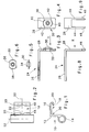
- FIG. 1 shows a cross section of a total of 10 designated bearing belt, which has an L-shaped angle 12, which is integrally formed on a bearing bush 14.
- the Bearing band 10 is with a (not shown) frame bearing part pivotally connected.
- the L-shaped bracket 12 has a free leg 16 which a plug-in rail 18 is integrally formed.
- This Insert rail 18 has two opposite one another Sidebars 20, which, as shown in Fig. 2, in their middle region are provided with recesses 22.
- the Recesses 22 are part-circular and lie towards each other.
- Fig. 3 shows part of a scissor arm 24, the a leg 26 on the wing of a door, a window or the like is attached, and the other leg 28 for Attachment to the bearing belt 10 is used.
- This leg 28 is equipped with a bolt 30, the bolt 30, which in Fig. 5 is shown in side view, in a recording 32 inserted and therein with its cylindrical portion 34 is so caulked that he is captive on the thigh 28 attached, but is still rotatable.
- the one cylindrical section 34 opposite side is with provided with an internal hexagon 36 (see Figure 6), in which inserted a tool and thereby the bolt 30 rotated can be.
- FIG. 4 shows a top view of the leg 28 in Direction of arrow IV in FIG. 3 with in the open position located bolt 30.
- the bolt portion 38 of the Latch 30 is essentially rectangular, however, two opposite sides 40 of the Bolt section 38 are formed part-circular. The Curvature of these sides 40 corresponds to the shape of the part-circular recesses 22. It can also be seen that the locking section 38 is provided with stops 42, which prevent overtightening of the bolt 30.
- the Latch from the position shown in Fig. 4 through Turn 90 ° clockwise in the Bolt position rotated, then the sides 40 engage in the Recesses 22 and the leg 28 is in the Insert rail 18 locked. This location is in the figure 7, in which the free leg 28 of the Scissor arms 24 attached to the bearing belt 10 via the bolt 30 is.
- the figures 8 and 9 show a second embodiment of the Scissor arm 24, which is also of legs 26 and 28th is formed, but with the leg 28 on his free end has two protruding fingers 44 on their free ends are provided with locking lugs 46.
- the detents 26 are initially after swiveled inside and snap behind after passing through Shoulders 48 and thereby block a pulling out of the leg 28 from the insertion rail 18.
- This Attachment of the scissor arm 24 on the bearing belt 10 is carried out without tools. It also doesn't matter if that Bearing belt 10 is provided with recesses 22 or not. To a scissor arm 24 locked in this way from the To remove the insertion rail 18, only the Lugs 26 compressed and the rear grip released become.
- the bearing belt 10 is mirror-symmetrical and a plane of symmetry 50, which is orthogonal to the pivot axis 52 of the Bearing belt stands.
- Fig. 10 shows a ribbon pin 54 as z. B. for Connection of the bearing belt 10 used on the frame bearing part becomes.
- the band pin 54 is in the bearing bush 14th plugged in.
- the band pin 54 is at one end with a coaxially inserted cheese head screw 56, which engages in a coaxial thread 58.
- Between the free end of the ribbon pin 54 and the head of the Cylinder screw 56 has an elastic ring 60 z. B. made of rubber, silicone rubber, spring steel or the like, on which when screwing in the cap screw 56 Head of the screw 56 is screwed on. This will make the elastic ring 60 squeezed and enlarged its Diameter. In this way, the ribbon pin 54 in the Bearing bush 14 or in a corresponding socket of the Frame bearing part can be locked.
- Diameter By more or less screwing in the cap screw 56 can Diameter can be set, which reduces the friction of the Band pin 54 is set in the socket. To this Ways of turning the ribbon pin as well as a Pulling out the ribbon pin can be prevented. is the elastic ring 60 is outside the socket, then only pulling out the ribbon pin 54 prevented.
Landscapes
- Engineering & Computer Science (AREA)
- Mechanical Engineering (AREA)
- Hinges (AREA)
- Door And Window Frames Mounted To Openings (AREA)
- Pivots And Pivotal Connections (AREA)
- Wing Frames And Configurations (AREA)
Abstract
Description
- Figur 1
- einen Querschnitt durch ein Lagerband;
- Figur 2
- eine Seitenansicht des Lagerbandes;
- Figur 3
- eine Seitenansicht eines Scherenarms, teilweise geschnitten, mit eingesetztem Riegel;
- Figur 4
- eine Ansicht des Scherenarms in Richtung des Pfeils IV gemäß Fig. 3;
- Figur 5
- eine Seitenansicht des Riegels;
- Figur 6
- eine Draufsicht auf den Riegel;
- Figur 7
- eine Draufsicht auf das Scherenlager bei in das Lagerband eingeschobenem Scherenarm;
- Figur 8
- eine Seitenansicht auf eine zweite Ausführungsform des Scherenarms;
- Figur 9
- eine Ansicht in Richtung des Pfeils IX gemäß Fig. 8 auf den Scherenarm; und
- Figur 10
- eine Ansicht eines teilweise aufgeschnittenen Lagerbolzen für das Lagerband.
Claims (18)
- Drehkipp-Beschlag für ein Fenster, eine Tür oder dergleichen aus Metall, z. B. Aluminium, mit einem oberen Scherenlager und einem unteren Ecklager, wobei das Scherenlager ein am Rahmen befestigbares Rahmenlagerteil, ein am Rahmenlagerteil schwenkbar gelagertes Lagerband (10) und einen am Lagerband (10) und am Flügel des Fensters, der Tür oder dergleichen befestigbaren Scherenarm (24) aufweist, dadurch gekennzeichnet, dass der Scherenarm (24) über eine Schnellverschlusseinrichtung mit dem Lagerband (10) lösbar verbindbar ist.
- Drehkipp-Beschlag nach Anspruch 1, dadurch gekennzeichnet, dass das Lagerband (10) eine vertikal ausgerichtete, im Wesentlichen C-förmig ausgebildete Einsteckschiene (18) aufweist.
- Drehkipp-Beschlag nach Anspruch 2, dadurch gekennzeichnet, dass die Einsteckschiene (18) am freien Schenkel (16) eines am Schwenklager angeformten L-Winkels (12) ausgebildet ist.
- Drehkipp-Beschlag nach Anspruch 3, dadurch gekennzeichnet, dass die Einsteckschiene (18) an der Innenseite des L-Winkels (12) vorgesehen ist.
- Drehkipp-Beschlag nach einem der vorhergehenden Ansprüche, dadurch gekennzeichnet, dass die Einsteckschiene (18) einander zugewandte Randleisten (20) aufweist, die in einem mittleren Bereich mit einer Ausnehmung (22) versehen sind.
- Drehkipp-Beschlag nach Anspruch 5, dadurch gekennzeichnet, dass die Ausnehmungen (22) an den beiden Randleisten (20) einander gegenüberliegen.
- Drehkipp-Beschlag nach Anspruch 5 oder 6, dadurch gekennzeichnet, dass die Ausnehmungen teilkreisförmig sind.
- Drehkipp-Beschlag nach einem der vorhergehenden Ansprüche, dadurch gekennzeichnet, dass der Scherenarm (24) L-förmig ausgebildet ist und mit einem Schenkel (28) in die Einsteckschiene (18) greift und darin lösbar verbindbar ist.
- Drehkipp-Beschlag nach Anspruch 8, dadurch gekennzeichnet, dass der mit der Einsteckschiene (18) verbindbare Schenkel (28) des Scherenarms (24) mit einem Riegel (30) versehen ist, der mit der Einsteckschiene (18) verriegelbar ist.
- Drehkipp-Beschlag nach Anspruch 9, dadurch gekennzeichnet, dass der Riegel (30) ein Dreh- oder Schwenkriegel ist.
- Drehkipp-Beschlag nach Anspruch 9 oder 10, dadurch gekennzeichnet, dass der Riegel (30) in einer Aufnahme (32) derart verstemmt ist, dass er unverlierbar, jedoch noch drehbar ist.
- Drehkipp-Beschlag nach einem der Ansprüche 9 bis 11, dadurch gekennzeichnet, dass der Riegel (30) mit einem Innensechskant (36) versehen ist.
- Drehkipp-Beschlag nach einem der Ansprüche 1 bis 8, dadurch gekennzeichnet, dass der mit der Einsteckschiene (18) verbundene Schenkel (28) des Scherenarms (24) mit einer Rastvorrichtung versehen ist, die mit dem Lagerband (10) verrastet.
- Drehkipp-Beschlag nach Anspruch 13, dadurch gekennzeichnet, dass der Schenkel (28) an seinem freien Ende zwei abragende Finger (44) aufweist, die an ihren freien Enden mit Rastnasen (46) versehen sind.
- Drehkipp-Beschlag nach Anspruch 14, dadurch gekennzeichnet, dass die Einsteckschiene (18) Rastöffnungen für die Rastnasen (46) aufweist.
- Drehkipp-Beschlag nach Anspruch 14, dadurch gekennzeichnet, dass die Einsteckschiene (18) von den Rastnasen (46) hintergreifbare Schultern (48) aufweist.
- Drehkipp-Beschlag nach einem der vorhergehenden Ansprüche, dadurch gekennzeichnet, dass das Lagerband (10) spiegelsymmetrisch ist.
- Drehkipp-Beschlag nach Anspruch 17, dadurch gekennzeichnet, dass die Schwenkachse (52) des Lagerbandes (10) orthogonal zur Symmetrieebene (50) liegt.
Applications Claiming Priority (2)
| Application Number | Priority Date | Filing Date | Title |
|---|---|---|---|
| DE20113606U DE20113606U1 (de) | 2001-08-09 | 2001-08-09 | Drehkipp-Beschlag |
| DE20113606U | 2001-08-09 |
Publications (3)
| Publication Number | Publication Date |
|---|---|
| EP1283320A2 true EP1283320A2 (de) | 2003-02-12 |
| EP1283320A3 EP1283320A3 (de) | 2008-04-16 |
| EP1283320B1 EP1283320B1 (de) | 2009-07-08 |
Family
ID=7960606
Family Applications (1)
| Application Number | Title | Priority Date | Filing Date |
|---|---|---|---|
| EP02011573A Expired - Lifetime EP1283320B1 (de) | 2001-08-09 | 2002-05-27 | Drehkipp-Beschlag |
Country Status (3)
| Country | Link |
|---|---|
| EP (1) | EP1283320B1 (de) |
| AT (1) | ATE435956T1 (de) |
| DE (2) | DE20113606U1 (de) |
Families Citing this family (1)
| Publication number | Priority date | Publication date | Assignee | Title |
|---|---|---|---|---|
| DE102022205247A1 (de) | 2022-05-25 | 2023-11-30 | Roto Frank Fenster- und Türtechnologie GmbH | Scharnierbeschlag zur horizontalen Flügelverstellung eines Fensters oder einer Tür |
Citations (4)
| Publication number | Priority date | Publication date | Assignee | Title |
|---|---|---|---|---|
| DE3402617A1 (de) | 1983-01-28 | 1984-08-02 | SLIM Società Lavorazioni Industriali Metalli S.p.A., Cisterna di Latina | Kippoeffnungsvorrichtung fuer mit kippfluegelmechanismus versehene fenster-, tuerfluegel oder aehnliche |
| EP0283984A1 (de) | 1987-03-20 | 1988-09-28 | ALPROGETTI S.r.l. | Selbstverriegelnde Befestigungsmittel, insbesondere für Profilteile von Einfassungen, Tür- und Fensterrahmen und dergleichen und mit diesem selbstverriegelnden Befestigungsmittel ausgerüstetes Zubehör |
| DE9401699U1 (de) | 1994-02-02 | 1994-03-17 | Roto Frank Ag | Ausstellvorrichtung für Fenster, Türen o.dgl. |
| EP0628692A2 (de) | 1993-06-10 | 1994-12-14 | Gretsch-Unitas GmbH Baubeschläge | Lagerelement eines oberen Drehlagers für einen wenigstens drehbar gelagerten Flügel eines Fensters, einer Tür oder dergleichen |
-
2001
- 2001-08-09 DE DE20113606U patent/DE20113606U1/de not_active Expired - Lifetime
-
2002
- 2002-05-27 DE DE50213661T patent/DE50213661D1/de not_active Expired - Lifetime
- 2002-05-27 AT AT02011573T patent/ATE435956T1/de not_active IP Right Cessation
- 2002-05-27 EP EP02011573A patent/EP1283320B1/de not_active Expired - Lifetime
Patent Citations (4)
| Publication number | Priority date | Publication date | Assignee | Title |
|---|---|---|---|---|
| DE3402617A1 (de) | 1983-01-28 | 1984-08-02 | SLIM Società Lavorazioni Industriali Metalli S.p.A., Cisterna di Latina | Kippoeffnungsvorrichtung fuer mit kippfluegelmechanismus versehene fenster-, tuerfluegel oder aehnliche |
| EP0283984A1 (de) | 1987-03-20 | 1988-09-28 | ALPROGETTI S.r.l. | Selbstverriegelnde Befestigungsmittel, insbesondere für Profilteile von Einfassungen, Tür- und Fensterrahmen und dergleichen und mit diesem selbstverriegelnden Befestigungsmittel ausgerüstetes Zubehör |
| EP0628692A2 (de) | 1993-06-10 | 1994-12-14 | Gretsch-Unitas GmbH Baubeschläge | Lagerelement eines oberen Drehlagers für einen wenigstens drehbar gelagerten Flügel eines Fensters, einer Tür oder dergleichen |
| DE9401699U1 (de) | 1994-02-02 | 1994-03-17 | Roto Frank Ag | Ausstellvorrichtung für Fenster, Türen o.dgl. |
Also Published As
| Publication number | Publication date |
|---|---|
| DE20113606U1 (de) | 2001-10-31 |
| DE50213661D1 (de) | 2009-08-20 |
| EP1283320A3 (de) | 2008-04-16 |
| ATE435956T1 (de) | 2009-07-15 |
| EP1283320B1 (de) | 2009-07-08 |
Similar Documents
| Publication | Publication Date | Title |
|---|---|---|
| EP3702562B1 (de) | Sicherungsbeschlagsteil sowie beschlaganordnung und rahmen- und flügelanordnung | |
| EP0822309A1 (de) | Rastpunktverstellung für Gelenkbänder | |
| DE2912881A1 (de) | Treibstangenverschluss, insbesondere fuer zweifluegelige feuerschutztueren | |
| EP0678636B1 (de) | Verbindungsvorrichtung für den Einbau des Flügels eines Wohndachfensters in den Futterkasten | |
| EP1830024A2 (de) | Beschlag für Fenster oder Türen | |
| EP3187671B1 (de) | Verriegelungsvorrichtung als einbruchssicherung für z. b. fenster und türen | |
| EP4083360B1 (de) | Drehkippfenster und beschlaganordnung | |
| DE2443866A1 (de) | Vorrichtung zur lagensicherung des ausstellarmes von ausstellvorrichtungen fuer fenster, tueren o.dgl. | |
| EP0478639A1 (de) | Scharnier. | |
| EP1746235B1 (de) | Beschlaganordnung | |
| EP1283320A2 (de) | Drehkipp-Beschlag | |
| DE2116144C3 (de) | Riegelbeschlag für Fenster und Türen o.dgl. | |
| EP1777363B1 (de) | Vorrichtung zum Arretieren einer Tür eines Gehäuses | |
| DE2443036C3 (de) | Ausstellvorrichtung | |
| DE102010027957B4 (de) | Eckband einer Ecklageranordnung | |
| EP1301676B1 (de) | Fenster oder tür mit entlastungseinrichtung | |
| WO2021073831A1 (de) | Band zur schwenkbaren verbindung eines flügels mit einem rahmen | |
| EP4045744B1 (de) | Beschlaganordnung | |
| DE102019128250B3 (de) | Band zur schwenkbaren Verbindung eines Flügels mit einem Rahmen | |
| DE102019128247B3 (de) | Band zur schwenkbaren Verbindung eines Flügels mit einem Rahmen | |
| EP2602413B1 (de) | Verriegelungseinrichtung zum Arretieren eines Fensterladens oder Türladens | |
| DE19603417C1 (de) | Vorrichtung zur Sicherung eines zwischen zwei Endstellungen bewegbaren Bauteils zum Verschließen einer Wandöffnung eines Gebäudes | |
| DE2404267A1 (de) | Ausstellvorrichtung fuer dreh-kippfenster, -tueren o.dgl. | |
| DE3348356C2 (en) | Tilting window casement or door wing extending arm | |
| DE3712026C2 (de) |
Legal Events
| Date | Code | Title | Description |
|---|---|---|---|
| PUAI | Public reference made under article 153(3) epc to a published international application that has entered the european phase |
Free format text: ORIGINAL CODE: 0009012 |
|
| AK | Designated contracting states |
Designated state(s): AT BE CH CY DE DK ES FI FR GB GR IE IT LI LU MC NL PT SE TR |
|
| AX | Request for extension of the european patent |
Extension state: AL LT LV MK RO SI |
|
| PUAL | Search report despatched |
Free format text: ORIGINAL CODE: 0009013 |
|
| AK | Designated contracting states |
Kind code of ref document: A3 Designated state(s): AT BE CH CY DE DK ES FI FR GB GR IE IT LI LU MC NL PT SE TR |
|
| AX | Request for extension of the european patent |
Extension state: AL LT LV MK RO SI |
|
| 17P | Request for examination filed |
Effective date: 20080331 |
|
| AKX | Designation fees paid |
Designated state(s): AT BE CH CY DE DK ES FI FR GB GR IE IT LI LU MC NL PT SE TR |
|
| GRAP | Despatch of communication of intention to grant a patent |
Free format text: ORIGINAL CODE: EPIDOSNIGR1 |
|
| GRAS | Grant fee paid |
Free format text: ORIGINAL CODE: EPIDOSNIGR3 |
|
| GRAA | (expected) grant |
Free format text: ORIGINAL CODE: 0009210 |
|
| AK | Designated contracting states |
Kind code of ref document: B1 Designated state(s): AT BE CH CY DE DK ES FI FR GB GR IE IT LI LU MC NL PT SE TR |
|
| REG | Reference to a national code |
Ref country code: GB Ref legal event code: FG4D Free format text: NOT ENGLISH |
|
| REG | Reference to a national code |
Ref country code: CH Ref legal event code: EP |
|
| REG | Reference to a national code |
Ref country code: IE Ref legal event code: FG4D |
|
| REF | Corresponds to: |
Ref document number: 50213661 Country of ref document: DE Date of ref document: 20090820 Kind code of ref document: P |
|
| NLV1 | Nl: lapsed or annulled due to failure to fulfill the requirements of art. 29p and 29m of the patents act | ||
| PG25 | Lapsed in a contracting state [announced via postgrant information from national office to epo] |
Ref country code: FI Free format text: LAPSE BECAUSE OF FAILURE TO SUBMIT A TRANSLATION OF THE DESCRIPTION OR TO PAY THE FEE WITHIN THE PRESCRIBED TIME-LIMIT Effective date: 20090708 Ref country code: ES Free format text: LAPSE BECAUSE OF FAILURE TO SUBMIT A TRANSLATION OF THE DESCRIPTION OR TO PAY THE FEE WITHIN THE PRESCRIBED TIME-LIMIT Effective date: 20091019 |
|
| REG | Reference to a national code |
Ref country code: IE Ref legal event code: FD4D |
|
| PG25 | Lapsed in a contracting state [announced via postgrant information from national office to epo] |
Ref country code: NL Free format text: LAPSE BECAUSE OF FAILURE TO SUBMIT A TRANSLATION OF THE DESCRIPTION OR TO PAY THE FEE WITHIN THE PRESCRIBED TIME-LIMIT Effective date: 20090708 |
|
| PG25 | Lapsed in a contracting state [announced via postgrant information from national office to epo] |
Ref country code: PT Free format text: LAPSE BECAUSE OF FAILURE TO SUBMIT A TRANSLATION OF THE DESCRIPTION OR TO PAY THE FEE WITHIN THE PRESCRIBED TIME-LIMIT Effective date: 20091109 |
|
| PG25 | Lapsed in a contracting state [announced via postgrant information from national office to epo] |
Ref country code: IE Free format text: LAPSE BECAUSE OF FAILURE TO SUBMIT A TRANSLATION OF THE DESCRIPTION OR TO PAY THE FEE WITHIN THE PRESCRIBED TIME-LIMIT Effective date: 20090708 Ref country code: DK Free format text: LAPSE BECAUSE OF FAILURE TO SUBMIT A TRANSLATION OF THE DESCRIPTION OR TO PAY THE FEE WITHIN THE PRESCRIBED TIME-LIMIT Effective date: 20090708 |
|
| PLBE | No opposition filed within time limit |
Free format text: ORIGINAL CODE: 0009261 |
|
| STAA | Information on the status of an ep patent application or granted ep patent |
Free format text: STATUS: NO OPPOSITION FILED WITHIN TIME LIMIT |
|
| 26N | No opposition filed |
Effective date: 20100409 |
|
| PG25 | Lapsed in a contracting state [announced via postgrant information from national office to epo] |
Ref country code: GR Free format text: LAPSE BECAUSE OF FAILURE TO SUBMIT A TRANSLATION OF THE DESCRIPTION OR TO PAY THE FEE WITHIN THE PRESCRIBED TIME-LIMIT Effective date: 20091009 |
|
| BERE | Be: lapsed |
Owner name: GRETSCH-UNITAS G.M.B.H. BAUBESCHLAGE Effective date: 20100531 |
|
| PG25 | Lapsed in a contracting state [announced via postgrant information from national office to epo] |
Ref country code: MC Free format text: LAPSE BECAUSE OF NON-PAYMENT OF DUE FEES Effective date: 20100531 |
|
| REG | Reference to a national code |
Ref country code: CH Ref legal event code: PL |
|
| GBPC | Gb: european patent ceased through non-payment of renewal fee |
Effective date: 20100527 |
|
| REG | Reference to a national code |
Ref country code: FR Ref legal event code: ST Effective date: 20110131 |
|
| PG25 | Lapsed in a contracting state [announced via postgrant information from national office to epo] |
Ref country code: CH Free format text: LAPSE BECAUSE OF NON-PAYMENT OF DUE FEES Effective date: 20100531 Ref country code: LI Free format text: LAPSE BECAUSE OF NON-PAYMENT OF DUE FEES Effective date: 20100531 |
|
| PG25 | Lapsed in a contracting state [announced via postgrant information from national office to epo] |
Ref country code: BE Free format text: LAPSE BECAUSE OF NON-PAYMENT OF DUE FEES Effective date: 20100531 Ref country code: IT Free format text: LAPSE BECAUSE OF FAILURE TO SUBMIT A TRANSLATION OF THE DESCRIPTION OR TO PAY THE FEE WITHIN THE PRESCRIBED TIME-LIMIT Effective date: 20090708 |
|
| PG25 | Lapsed in a contracting state [announced via postgrant information from national office to epo] |
Ref country code: FR Free format text: LAPSE BECAUSE OF NON-PAYMENT OF DUE FEES Effective date: 20100531 |
|
| PG25 | Lapsed in a contracting state [announced via postgrant information from national office to epo] |
Ref country code: GB Free format text: LAPSE BECAUSE OF NON-PAYMENT OF DUE FEES Effective date: 20100527 |
|
| PG25 | Lapsed in a contracting state [announced via postgrant information from national office to epo] |
Ref country code: AT Free format text: LAPSE BECAUSE OF NON-PAYMENT OF DUE FEES Effective date: 20100527 |
|
| PG25 | Lapsed in a contracting state [announced via postgrant information from national office to epo] |
Ref country code: CY Free format text: LAPSE BECAUSE OF FAILURE TO SUBMIT A TRANSLATION OF THE DESCRIPTION OR TO PAY THE FEE WITHIN THE PRESCRIBED TIME-LIMIT Effective date: 20090708 |
|
| PG25 | Lapsed in a contracting state [announced via postgrant information from national office to epo] |
Ref country code: LU Free format text: LAPSE BECAUSE OF NON-PAYMENT OF DUE FEES Effective date: 20100527 Ref country code: SE Free format text: LAPSE BECAUSE OF FAILURE TO SUBMIT A TRANSLATION OF THE DESCRIPTION OR TO PAY THE FEE WITHIN THE PRESCRIBED TIME-LIMIT Effective date: 20090708 |
|
| PG25 | Lapsed in a contracting state [announced via postgrant information from national office to epo] |
Ref country code: TR Free format text: LAPSE BECAUSE OF FAILURE TO SUBMIT A TRANSLATION OF THE DESCRIPTION OR TO PAY THE FEE WITHIN THE PRESCRIBED TIME-LIMIT Effective date: 20090708 |
|
| PGFP | Annual fee paid to national office [announced via postgrant information from national office to epo] |
Ref country code: DE Payment date: 20150521 Year of fee payment: 14 |
|
| REG | Reference to a national code |
Ref country code: DE Ref legal event code: R119 Ref document number: 50213661 Country of ref document: DE |
|
| PG25 | Lapsed in a contracting state [announced via postgrant information from national office to epo] |
Ref country code: DE Free format text: LAPSE BECAUSE OF NON-PAYMENT OF DUE FEES Effective date: 20161201 |