EP1283088A1 - Vorrichtung und Verfahren zur Bewertung des Abnützungsgrades einer Elektrodedüse in Schutzgas-Lichtbogenschweissen mit abschmelzender Elektrode - Google Patents
Vorrichtung und Verfahren zur Bewertung des Abnützungsgrades einer Elektrodedüse in Schutzgas-Lichtbogenschweissen mit abschmelzender Elektrode Download PDFInfo
- Publication number
- EP1283088A1 EP1283088A1 EP02078307A EP02078307A EP1283088A1 EP 1283088 A1 EP1283088 A1 EP 1283088A1 EP 02078307 A EP02078307 A EP 02078307A EP 02078307 A EP02078307 A EP 02078307A EP 1283088 A1 EP1283088 A1 EP 1283088A1
- Authority
- EP
- European Patent Office
- Prior art keywords
- welding
- arc
- wear
- time
- electrode tip
- Prior art date
- Legal status (The legal status is an assumption and is not a legal conclusion. Google has not performed a legal analysis and makes no representation as to the accuracy of the status listed.)
- Granted
Links
Images


Classifications
-
- B—PERFORMING OPERATIONS; TRANSPORTING
- B23—MACHINE TOOLS; METAL-WORKING NOT OTHERWISE PROVIDED FOR
- B23K—SOLDERING OR UNSOLDERING; WELDING; CLADDING OR PLATING BY SOLDERING OR WELDING; CUTTING BY APPLYING HEAT LOCALLY, e.g. FLAME CUTTING; WORKING BY LASER BEAM
- B23K9/00—Arc welding or cutting
- B23K9/24—Features related to electrodes
- B23K9/26—Accessories for electrodes, e.g. ignition tips
Definitions
- the present invention is related to an apparatus and method for assessing the state of wear of electrode tips used in consumable electrode gas shielded arc welding.
- an 'electrode tip' has a consumable electrode (hereinafter, 'welding wire') inserted through it in a manner such that there is electrical conta ct between the wire and the tip. Electrical power is then supplied to the welding wire through the electrode tip. The wire is fed through a hole in the electrode tip, causing the hole to wear. This wear progresses over time, causing the points of contact between the wire and the electrode tip (the points through which power is supplied) to shift, which in turn results in fluctuations in the state of the electrical power supplied to the wire. This causes arc instability phenomena to occur during welding.
- electrode tips must be replaced when they become too worn.
- this tip replacement was performed either whenever deemed necessary by an equipment operator, based on his experience in visual observation of arc instability, or periodically, based on the accumulated operating time of the tip.
- the present invention is directed to an apparatus and method to solve this problem. It is an object of the present invention to provide an apparatus and method for assessment of electrode tip wear that can perform accurate quantitative assessment of the state of wear of an electrode tip, thereby to provide a precise assessment as to the optimum timing for electrode tip replacement. This object is achieved through the technology described below.
- an apparatus for assessing electrode tip wear is characterized in that, in consumable electrode gas-shielded arc welding, wherein a welding voltage is applied to an electrode tip having a wire inserted therein in electrical contact therewith, for performing arc welding by causing droplets to be transferred from the welding wire onto a workpiece to be welded, it comprises: a welding voltage detection means, or a welding current detection means, for detecting welding voltage applied between the welding wire and the workpiece, or the welding current supplied; a replacement index computation means for computing an electrode tip replacement index based on the average value of the arc-time welding voltage, or arc-time welding current, as detected by the welding voltage detection means or welding current detection means; and a wear assessment means for assessing the state of wear of the electrode tip by co mparing the replacement index computed by the replacement index computation means with a reference standard value.
- arc-lime welding voltage' and 'arc-time welding current' in the above description (and in the followin g) refer to that portion of the welding voltage and welding current that does not occur during the short-circuit time.
- an electrode tip replacement index is computed by the replacement index computation means, based on the average value of the arc-time welding voltage or arc-time welding current as detected by the welding voltage or welding current detection means.
- the wear assessment means then compares the computed replacement index value with a reference standard value , thus to provide a precise assessment as to the state of wear of the electrode tip.
- a method for assessing electrode tip wear in consumable electrode gas -shielded arc welding wherein a welding voltage is applied to an electrode tip having a wire inserted therein in electrical contact therewith, for performing arc welding by causing droplets to be transferred from the welding wire onto a workpiece to be welded, is characterized in that it comprises: a step of detecting welding voltage applied between the welding wire and the workpiece, or welding current supplied; a step of computing an electrode tip replacement index based on the quotient of the instant average arc - time welding voltage, or arc-time welding current, divided by the average arc -time welding voltage, or arc-time welding current, respectively, immediately following tip replacement; and a step of assessing the state of wear of the electrode tip by comparing the value of the replacement index computed by the replacement index computation means with a prescribed assessment threshold value.
- an electrode tip replacement index is computed, based on the quotient of the instant average arc-time welding voltage, or arc-time welding current, divided by the average arc-time welding voltage, or arc-time welding current, respectively, immediately following tip replacement, and an assessment is performed by comparing the value of this computed replacement index to an assessment threshold value (which is set to a value at which it has been determined in advance that electrode tip replacement will be necessary). This makes it possible to provide a precise assessment of optimum electrode tip replacement timing.
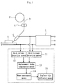
- Fig. 1 is a block diagram showing the overall configuration of a consumable electrode gas shielded arc welding system (hereinafter, 'arc welding system'), including the assessment apparatus of the present invention.
- the system comprises a welding power supply 1; a takeup reel 2 around which a welding wire 3 is wound for containment thereon; a feed roller 4 for feeding welding wire 3 toward a welding workpiece 6; and an electrically conductive electrode tip 5 for holding the forward end of the welding wire 3, and supplying electrical power from the welding power supply 1 to the welding wire 3.
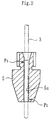
- a through-hole 5a through which the welding wire 3 is passed, is provided within the electrode tip 5.
- the outer surface of the welding wire 3 makes electrical contact with two contacts (P1 and P 2) provided on the inside surface of the through-hole 5a, near its two ends. These two contacts (P1 and P2) are the electrical power supply points for the welding wire 3.
- a welding voltage detection means 11 for detecting welding voltage applied between the welding wire 3 and the welding workpiece 6, and a welding current detection means 12, for detecting welding current supplied from the welding wire 3 to the welding workpiece 6.
- a replacement index computation means 13 computes a replacement index (hereinafter 'tip replacement index,') to be described later, based on the arc -time welding voltage and arc-time welding current detected by these two detection means (11 and 12).
- the tip replacement index thus computed is used by an electrode tip wear assessment means 14 to perform wear assessment. If the assessed wear value exceeds a reference standard value, a 'replace tip' indication is displayed by a replace tip indicator means 15.
- Arc-time welding voltage and arc-time welding current can easily be detected by setting a prescribed voltage threshold to a level that will filter out the short -circuit time voltage and current waveforms from the continuously detected welding voltage and welding current waveforms.
- Fig. 3 shows a typical example of the voltage and current waveforms detected by the welding voltage detection means 11 and welding current detection means 12, and the corresponding droplet -transfer phenomena that occur in the arc welding process. Over one short -circuit-and-arc cycle going from (A) to (H) in Fig.
- T S(n) is the short-circuit time of the n th cycle
- T A(n) is the arc time of the n th cycle
- T S(n+1) is the short-circuit time of the (n + 1) th cycle.
- V A(n)av is the average arc-time welding voltage of the n th cycle
- I A(n)av is the average arc-time welding current of the n th cycle.
- the assessment apparatus circuit includes a processor (CPU) 20, a memory (ROM) 21, memory (RAM) 22, an input interface 23, an output interface 24, and peripherals (keyboard, monitor, printer, etc.) 25 (all of the above items being included in a controller 26), an A/D converter 30, a welding voltage detection circuit 31, a welding current detection circuit 32, and a tip replacement indicator unit 33.
- ROM memory 21 Stored in the ROM memory 21 is a program (assessment program) providing a number of processes (included in a flow chart to be discussed later) required to assess electrode tip wear.
- the assessment program executes whenever the processor is 20 is started up. Variable data required to run the assessment program is temporarily stored in the RAM memory 22.
- average values of arc-time welding voltage and welding current are output from the two detection circuits 31 and 32, through the A/D converters 30, and input interface 23, for inpu t to the processor 20.
- the processor 20 computes a tip replacement index, and if the value of that index exceeds a reference standard value, a signal is output through the output interface 24 to the tip replacement indicator unit 33, which responds by prod ucing a 'replace tip' indication, such as a flashing lamp.
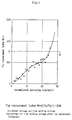
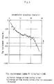
- Fig. 5 and Fig. 6 show results obtained in an experiment conducted to determine the relationship between the accumulated arc welding operation time of the tip, and the tip replacement index.
- the data in Fig. 5 reveal that as a tip's accumulated operating time increases (as it becomes more worn), the arc-time welding voltage increases, and the value of the tip replacement index increases. It was determined that a decision to replace the tip should be made when the index exceeds the decision threshold value A.
- the data in Fig. 6 show that as a tip's accumulated operating time increases, the average arc-time welding current decreases, and the value of the tip replacement index decreases. It was determined that a decision to replace the tip should be made when the value of the index falls below the decision threshold value B.
- Step 107 sampling is initiated by the start of arc welding (Steps 101 and 102) and ends when arc welding ends ( Steps 103 and 104).
- Step 105 the tip replacement index is computed as described above.
- Step 106 the tip replacement index based on average arc -time welding voltage, or the tip replacement index based on average arc time welding current is compared with its respective assessment threshold value (A or B) to make a tip wear pass/fail (tip wear acceptable or not acceptable) decision. If the tip replacement index has crossed the applicable assessment threshold value (A or B), an electrode tip replacement signal is output (Step 107).
- Step 201 The detailed flow chart of Fig. 8 starts in Step 201 by starting the welding voltage and welding current sampling process.
- Step 202 execution waits for the end of the no-load voltage time (the time prior to the shortin g of the wire 3 to the workpiece 6), after which measurement of welding voltage and welding current during the steady state welding time is begun (Step 203).
- Step 204 execution asks if the welding voltage V equals or exceeds the level V W1 (See Fig. 3), which is the level above which arc-time welding voltage and arc-time welding current assessment can be performed . If it does, measurement of arc-time welding voltage and welding current during the steady state welding time begins (Step 205). As this measurement proceeds, execution repeatedly checks to see if V has fallen below the level of the assessment voltage V W1 (Step 206). When V drops below V W1 , measurement of arc-time welding voltage and welding current during the steady state welding time ends (Step 207). Next, in Step 208, execution asks if time is up (i.e., if has sampling time ended). If it has, a tip replacement index is computed, as described above (Step 209).
- V W1 See Fig. 3
- Step 204 if the welding voltage V had been less than the V W1 reference level, execution would have gone to Step 208, bypassing Steps 205 through 207.
- either the welding voltage detection means 11 and the welding voltage detection circuit 31, or the welding current detection means 12 and the welding current detection circuit 32 may be omitted from the configuration
- the electrode tip wear assessment apparatus and assessment method of the present invention it is possible to make a precise assessment of the optimum timing for replacement of electrode tips due to wear sustained during arc welding. Thus replacement of electrode tips before they have reached their limit of wear can be avoided. This will reduce welding system down time for tip replacement, and also prevent the occurrence of arc welding quality defects due to the use of electrode tips that have exceeded their wear limits.
Applications Claiming Priority (2)
| Application Number | Priority Date | Filing Date | Title |
|---|---|---|---|
| JP2001243655A JP4703910B2 (ja) | 2001-08-10 | 2001-08-10 | 電極チップ摩耗状態の判定装置及び判定方法 |
| JP2001243655 | 2001-08-10 |
Publications (2)
| Publication Number | Publication Date |
|---|---|
| EP1283088A1 true EP1283088A1 (de) | 2003-02-12 |
| EP1283088B1 EP1283088B1 (de) | 2005-05-04 |
Family
ID=19073715
Family Applications (1)
| Application Number | Title | Priority Date | Filing Date |
|---|---|---|---|
| EP02078307A Expired - Lifetime EP1283088B1 (de) | 2001-08-10 | 2002-08-09 | Vorrichtung und Verfahren zur Bewertung des Abnützungsgrades einer Elektrodendüse im Schutzgas-Lichtbogenschweissen mit abschmelzender Elektrode |
Country Status (4)
| Country | Link |
|---|---|
| US (1) | US6639181B2 (de) |
| EP (1) | EP1283088B1 (de) |
| JP (1) | JP4703910B2 (de) |
| DE (1) | DE60203970T2 (de) |
Cited By (7)
| Publication number | Priority date | Publication date | Assignee | Title |
|---|---|---|---|---|
| FR2906169A1 (fr) * | 2006-09-25 | 2008-03-28 | Air Liquide | Procede de detection automatique de l'usure d'une electrode de soudage |
| WO2008079492A1 (en) * | 2006-12-22 | 2008-07-03 | Illinois Tool Works Inc. | System and method for identifying welding consumable wear |
| US20110073580A1 (en) * | 2009-09-25 | 2011-03-31 | Illinois Tool Works Inc. | Method to monitor the life of the contact tip in robotic or automatic gmaw |
| WO2012125670A1 (en) * | 2011-03-14 | 2012-09-20 | Illinois Tool Works Inc. | Method for providing real-time monitoring of contact tip performance |
| US9227270B2 (en) | 2012-11-30 | 2016-01-05 | Illinois Tool Works Inc. | Method to monitor the life of the contact tip in GMAW-pulse |
| EP1940578B1 (de) | 2005-09-08 | 2017-05-24 | Kemppi Oy | Verfahren zum Schweissen mit kurzem Lichtbogen |
| EP3912755A1 (de) | 2020-05-19 | 2021-11-24 | FRONIUS INTERNATIONAL GmbH | Verfahren zur ermittlung des verschleisses eines kontaktrohres während eines robotergestützten schweissverfahrens |
Families Citing this family (14)
| Publication number | Priority date | Publication date | Assignee | Title |
|---|---|---|---|---|
| CA2465915C (en) * | 2001-11-07 | 2010-09-14 | Commonwealth Scientific And Industrial Research Organisation | Improved consumable electrode arc welding |
| AU2006201216B2 (en) * | 2002-08-28 | 2006-11-23 | Lincoln Global, Inc. | System and method for determining and employing consumable use by electric arc welders |
| US10144080B2 (en) * | 2005-08-25 | 2018-12-04 | Lincoln Global, Inc. | Torch for electric arc welding or plasma cutting system |
| US8431862B2 (en) | 2005-08-25 | 2013-04-30 | Lincoln Global, Inc. | Torch for electric arc welding system |
| AT502419B1 (de) * | 2005-09-09 | 2007-08-15 | Fronius Int Gmbh | Schweissbrenner und verfahren zur prozesssteuerung einer schweissanlage |
| US8847100B2 (en) * | 2008-01-08 | 2014-09-30 | Fanuc America Corporation | Weld cap and tip inspection method and apparatus |
| CA2826944C (en) * | 2011-03-14 | 2016-05-17 | Illinois Tool Works Inc. | Method and apparatus to maintain welding current to compensate for deterioration of welding contact tip |
| JP5808947B2 (ja) * | 2011-05-23 | 2015-11-10 | 株式会社ダイヘン | 消耗電極アーク溶接のくびれ検出制御方法 |
| JP6395644B2 (ja) * | 2015-02-27 | 2018-09-26 | 株式会社神戸製鋼所 | アーク溶接方法、アーク溶接装置およびアーク溶接用制御装置 |
| US11204394B2 (en) | 2017-09-20 | 2021-12-21 | Esab Ab | External connector and sensor unit for welding equipment |
| JP7304224B2 (ja) * | 2019-07-09 | 2023-07-06 | 株式会社ダイヘン | 制御装置、プログラム、及びロボット制御システム |
| CN112775528B (zh) * | 2020-12-22 | 2022-09-27 | 上海电力大学 | 一种自动评估电阻点焊钳刚性的方法 |
| CN113533438B (zh) * | 2021-07-26 | 2024-04-09 | 中国科学院宁波材料技术与工程研究所 | 电接触材料摩擦电弧烧损的原位测试装置及其测试方法 |
| DE102022101534A1 (de) | 2022-01-24 | 2023-07-27 | Gottfried Wilhelm Leibniz Universität Hannover | Verfahren und Vorrichtung zur Durchführung eines Lichtbogen-Schweißprozesses |
Citations (6)
| Publication number | Priority date | Publication date | Assignee | Title |
|---|---|---|---|---|
| DD259162A1 (de) * | 1986-07-22 | 1988-08-17 | Zentralinstitut Schweiss | Verfahren zur erfassung und elektrischen umsetzung des verschleisszustandes von stromkontaktduesen |
| US5221825A (en) * | 1992-06-01 | 1993-06-22 | The United States Of America As Represented By The Secretary Of Commerce | Sensing of gas metal arc welding process characteristics for welding process control |
| JPH06198440A (ja) * | 1992-12-28 | 1994-07-19 | Nippon Steel Corp | アーク溶接ノズルの摩耗検知方法 |
| JPH10244366A (ja) * | 1997-03-04 | 1998-09-14 | Daihen Corp | 短絡移行アーク溶接における溶接チップの消耗度検出方法および検出装置 |
| JP2000024779A (ja) * | 1998-07-09 | 2000-01-25 | Hitachi Zosen Corp | 溶接チップの寿命評価方法および装置 |
| JP2001018064A (ja) * | 1999-07-05 | 2001-01-23 | Matsushita Electric Ind Co Ltd | プラズマ溶接装置 |
Family Cites Families (6)
| Publication number | Priority date | Publication date | Assignee | Title |
|---|---|---|---|---|
| JP3441237B2 (ja) * | 1995-05-26 | 2003-08-25 | 新日本製鐵株式会社 | シールドガス溶接機の点弧チップの摩耗判定方法および装置 |
| JPH10296441A (ja) * | 1997-04-25 | 1998-11-10 | Daihen Corp | 短絡移行アーク溶接における溶接チップの消耗度検出方法および検出装置 |
| JP3898811B2 (ja) * | 1997-10-22 | 2007-03-28 | 中央精機株式会社 | アーク溶接定常部の溶接安定性判定方法及び安定性判定装置 |
| JP3898812B2 (ja) * | 1997-10-22 | 2007-03-28 | 中央精機株式会社 | アーク溶接終端処理部の溶接安定性判定方法及び安定性判定装置 |
| US6130407A (en) * | 1998-07-29 | 2000-10-10 | Tregaskiss, Ltd. | Arc welding torch |
| JP2001232471A (ja) * | 2000-02-23 | 2001-08-28 | Babcock Hitachi Kk | 狭開先gma溶接のアーク揺動振り幅異常検出方法 |
-
2001
- 2001-08-10 JP JP2001243655A patent/JP4703910B2/ja not_active Expired - Fee Related
-
2002
- 2002-08-09 US US10/064,715 patent/US6639181B2/en not_active Expired - Fee Related
- 2002-08-09 EP EP02078307A patent/EP1283088B1/de not_active Expired - Lifetime
- 2002-08-09 DE DE60203970T patent/DE60203970T2/de not_active Expired - Fee Related
Patent Citations (6)
| Publication number | Priority date | Publication date | Assignee | Title |
|---|---|---|---|---|
| DD259162A1 (de) * | 1986-07-22 | 1988-08-17 | Zentralinstitut Schweiss | Verfahren zur erfassung und elektrischen umsetzung des verschleisszustandes von stromkontaktduesen |
| US5221825A (en) * | 1992-06-01 | 1993-06-22 | The United States Of America As Represented By The Secretary Of Commerce | Sensing of gas metal arc welding process characteristics for welding process control |
| JPH06198440A (ja) * | 1992-12-28 | 1994-07-19 | Nippon Steel Corp | アーク溶接ノズルの摩耗検知方法 |
| JPH10244366A (ja) * | 1997-03-04 | 1998-09-14 | Daihen Corp | 短絡移行アーク溶接における溶接チップの消耗度検出方法および検出装置 |
| JP2000024779A (ja) * | 1998-07-09 | 2000-01-25 | Hitachi Zosen Corp | 溶接チップの寿命評価方法および装置 |
| JP2001018064A (ja) * | 1999-07-05 | 2001-01-23 | Matsushita Electric Ind Co Ltd | プラズマ溶接装置 |
Non-Patent Citations (4)
| Title |
|---|
| PATENT ABSTRACTS OF JAPAN vol. 018, no. 554 (M - 1691) 21 October 1994 (1994-10-21) * |
| PATENT ABSTRACTS OF JAPAN vol. 1998, no. 14 31 December 1998 (1998-12-31) * |
| PATENT ABSTRACTS OF JAPAN vol. 2000, no. 04 31 August 2000 (2000-08-31) * |
| PATENT ABSTRACTS OF JAPAN vol. 2000, no. 16 8 May 2001 (2001-05-08) * |
Cited By (13)
| Publication number | Priority date | Publication date | Assignee | Title |
|---|---|---|---|---|
| EP1940578B1 (de) | 2005-09-08 | 2017-05-24 | Kemppi Oy | Verfahren zum Schweissen mit kurzem Lichtbogen |
| FR2906169A1 (fr) * | 2006-09-25 | 2008-03-28 | Air Liquide | Procede de detection automatique de l'usure d'une electrode de soudage |
| EP1905528A1 (de) * | 2006-09-25 | 2008-04-02 | L'AIR LIQUIDE, Société Anonyme pour l'Etude et l'Exploitation des Procédés Georges Claude | Verfahren zur automatischen Erkennung der Abnutzung einer Schweißelektrode durch Bemessung oder Abzählen während des Schweissens der Zahl der Lichtbogenzündungen dieser Elektrode. |
| WO2008079492A1 (en) * | 2006-12-22 | 2008-07-03 | Illinois Tool Works Inc. | System and method for identifying welding consumable wear |
| US8592719B2 (en) | 2006-12-22 | 2013-11-26 | Illinois Tool Works Inc. | System and method for identifying welding consumable wear |
| US8354614B2 (en) | 2009-09-25 | 2013-01-15 | Illinois Tool Works Inc. | Method to monitor the life of the contact tip in robotic or automatic GMAW |
| WO2011037674A1 (en) | 2009-09-25 | 2011-03-31 | Illinois Tool Works Inc. | Method to monitor the life of the contact tip in robotic or automatic gmaw |
| US20110073580A1 (en) * | 2009-09-25 | 2011-03-31 | Illinois Tool Works Inc. | Method to monitor the life of the contact tip in robotic or automatic gmaw |
| WO2012125670A1 (en) * | 2011-03-14 | 2012-09-20 | Illinois Tool Works Inc. | Method for providing real-time monitoring of contact tip performance |
| US8809738B2 (en) | 2011-03-14 | 2014-08-19 | Illinois Tool Works Inc. | Method for providing real-time monitoring of contact tip performance |
| US9227270B2 (en) | 2012-11-30 | 2016-01-05 | Illinois Tool Works Inc. | Method to monitor the life of the contact tip in GMAW-pulse |
| EP3912755A1 (de) | 2020-05-19 | 2021-11-24 | FRONIUS INTERNATIONAL GmbH | Verfahren zur ermittlung des verschleisses eines kontaktrohres während eines robotergestützten schweissverfahrens |
| WO2021233891A1 (de) | 2020-05-19 | 2021-11-25 | Fronius International Gmbh | VERFAHREN ZUR ERMITTLUNG DES VERSCHLEIßES EINES KONTAKTROHRES WÄHREND EINES ROBOTERGESTÜTZTEN SCHWEIßVERFAHRENS |
Also Published As
| Publication number | Publication date |
|---|---|
| DE60203970T2 (de) | 2006-01-19 |
| DE60203970D1 (de) | 2005-06-09 |
| US6639181B2 (en) | 2003-10-28 |
| JP2003053547A (ja) | 2003-02-26 |
| JP4703910B2 (ja) | 2011-06-15 |
| EP1283088B1 (de) | 2005-05-04 |
| US20030029851A1 (en) | 2003-02-13 |
Similar Documents
| Publication | Publication Date | Title |
|---|---|---|
| US6639181B2 (en) | Apparatus and method for assessing electrode tip wear | |
| US6703585B2 (en) | Arc welding quality evaluation apparatus | |
| US20020170899A1 (en) | Welding stability assessment apparatus for pulsed arc welding | |
| US6031203A (en) | Method and apparatus for determining stability of arc welding | |
| CN109834367B (zh) | 用于焊炬摆动的系统和方法 | |
| EP2253407B1 (de) | System zur Überwachung von Lichtbogenschweißverfahren und entsprechendes Überwachungsverfahren | |
| EP1206992B9 (de) | Vorrichtung und Verfahren zum Überwachen des Lichtbogenschweissens | |
| CN101152681A (zh) | 自动检测焊接电极损耗的方法 | |
| JP3898810B2 (ja) | アークスタート時の溶接安定性判定方法及び安定性判定装置 | |
| JP3898811B2 (ja) | アーク溶接定常部の溶接安定性判定方法及び安定性判定装置 | |
| JP2000024779A (ja) | 溶接チップの寿命評価方法および装置 | |
| JP4534770B2 (ja) | 溶接監視装置と溶接監視方法 | |
| JP3441237B2 (ja) | シールドガス溶接機の点弧チップの摩耗判定方法および装置 | |
| JP4271293B2 (ja) | アーク溶接の最適制御方法及び装置 | |
| JP2002001534A (ja) | アーク溶接モニタリング方法とその装置 | |
| JP3898812B2 (ja) | アーク溶接終端処理部の溶接安定性判定方法及び安定性判定装置 | |
| JP2000158134A (ja) | アーク溶接安定性判定方法及び装置 | |
| JP3233904B2 (ja) | 自動溶接装置 | |
| JPH072275B2 (ja) | アーク溶接モニタ装置 | |
| JP2920657B2 (ja) | プラズマ加工機の電極寿命検出装置 | |
| JPH08155644A (ja) | アーク溶接モニタ装置 | |
| JP3241527B2 (ja) | 消耗電極式ガスシールドアーク溶接装置 | |
| JP2006122950A (ja) | スポット溶接監視装置 | |
| JP2002321053A (ja) | パルスアーク溶接の溶接安定性判定装置 | |
| JPH05115978A (ja) | プラズマアーク加工機の異常検出装置 |
Legal Events
| Date | Code | Title | Description |
|---|---|---|---|
| PUAI | Public reference made under article 153(3) epc to a published international application that has entered the european phase |
Free format text: ORIGINAL CODE: 0009012 |
|
| AK | Designated contracting states |
Designated state(s): AT BE BG CH CY CZ DE DK EE ES FI FR GB GR IE IT LI LU MC NL PT SE SK TR |
|
| AX | Request for extension of the european patent |
Extension state: AL LT LV MK RO SI |
|
| 17P | Request for examination filed |
Effective date: 20030812 |
|
| AKX | Designation fees paid |
Designated state(s): DE FR GB IT |
|
| 17Q | First examination report despatched |
Effective date: 20040114 |
|
| GRAP | Despatch of communication of intention to grant a patent |
Free format text: ORIGINAL CODE: EPIDOSNIGR1 |
|
| RIN1 | Information on inventor provided before grant (corrected) |
Inventor name: SUZUKI, YUKIMITSU,C/O CENTRAL MOTOR WHEEL CO.,LTD Inventor name: ONISHI, KOJI,C/O CENTRAL MOTOR WHEEL CO., LTD |
|
| GRAS | Grant fee paid |
Free format text: ORIGINAL CODE: EPIDOSNIGR3 |
|
| GRAA | (expected) grant |
Free format text: ORIGINAL CODE: 0009210 |
|
| AK | Designated contracting states |
Kind code of ref document: B1 Designated state(s): DE FR GB IT |
|
| PG25 | Lapsed in a contracting state [announced via postgrant information from national office to epo] |
Ref country code: IT Free format text: LAPSE BECAUSE OF FAILURE TO SUBMIT A TRANSLATION OF THE DESCRIPTION OR TO PAY THE FEE WITHIN THE PRESCRIBED TIME-LIMIT;WARNING: LAPSES OF ITALIAN PATENTS WITH EFFECTIVE DATE BEFORE 2007 MAY HAVE OCCURRED AT ANY TIME BEFORE 2007. THE CORRECT EFFECTIVE DATE MAY BE DIFFERENT FROM THE ONE RECORDED. Effective date: 20050504 |
|
| REG | Reference to a national code |
Ref country code: GB Ref legal event code: FG4D |
|
| REF | Corresponds to: |
Ref document number: 60203970 Country of ref document: DE Date of ref document: 20050609 Kind code of ref document: P |
|
| PLBE | No opposition filed within time limit |
Free format text: ORIGINAL CODE: 0009261 |
|
| STAA | Information on the status of an ep patent application or granted ep patent |
Free format text: STATUS: NO OPPOSITION FILED WITHIN TIME LIMIT |
|
| 26N | No opposition filed |
Effective date: 20060207 |
|
| EN | Fr: translation not filed | ||
| GBPC | Gb: european patent ceased through non-payment of renewal fee |
Effective date: 20060809 |
|
| PG25 | Lapsed in a contracting state [announced via postgrant information from national office to epo] |
Ref country code: GB Free format text: LAPSE BECAUSE OF NON-PAYMENT OF DUE FEES Effective date: 20060809 |
|
| PG25 | Lapsed in a contracting state [announced via postgrant information from national office to epo] |
Ref country code: FR Free format text: LAPSE BECAUSE OF NON-PAYMENT OF DUE FEES Effective date: 20050831 |
|
| PGFP | Annual fee paid to national office [announced via postgrant information from national office to epo] |
Ref country code: DE Payment date: 20080825 Year of fee payment: 7 |
|
| PG25 | Lapsed in a contracting state [announced via postgrant information from national office to epo] |
Ref country code: FR Free format text: LAPSE BECAUSE OF NON-PAYMENT OF DUE FEES Effective date: 20050504 |
|
| PG25 | Lapsed in a contracting state [announced via postgrant information from national office to epo] |
Ref country code: DE Free format text: LAPSE BECAUSE OF NON-PAYMENT OF DUE FEES Effective date: 20100302 |