EP1283005B1 - Kombiniertes sensor- und heizelement - Google Patents
Kombiniertes sensor- und heizelement Download PDFInfo
- Publication number
- EP1283005B1 EP1283005B1 EP01940354A EP01940354A EP1283005B1 EP 1283005 B1 EP1283005 B1 EP 1283005B1 EP 01940354 A EP01940354 A EP 01940354A EP 01940354 A EP01940354 A EP 01940354A EP 1283005 B1 EP1283005 B1 EP 1283005B1
- Authority
- EP
- European Patent Office
- Prior art keywords
- sensor
- heating element
- element according
- combined sensor
- heat conductor
- Prior art date
- Legal status (The legal status is an assumption and is not a legal conclusion. Google has not performed a legal analysis and makes no representation as to the accuracy of the status listed.)
- Expired - Lifetime
Links
Images
Classifications
-
- G—PHYSICS
- G01—MEASURING; TESTING
- G01G—WEIGHING
- G01G19/00—Weighing apparatus or methods adapted for special purposes not provided for in the preceding groups
- G01G19/40—Weighing apparatus or methods adapted for special purposes not provided for in the preceding groups with provisions for indicating, recording, or computing price or other quantities dependent on the weight
- G01G19/413—Weighing apparatus or methods adapted for special purposes not provided for in the preceding groups with provisions for indicating, recording, or computing price or other quantities dependent on the weight using electromechanical or electronic computing means
- G01G19/414—Weighing apparatus or methods adapted for special purposes not provided for in the preceding groups with provisions for indicating, recording, or computing price or other quantities dependent on the weight using electromechanical or electronic computing means using electronic computing means only
- G01G19/4142—Weighing apparatus or methods adapted for special purposes not provided for in the preceding groups with provisions for indicating, recording, or computing price or other quantities dependent on the weight using electromechanical or electronic computing means using electronic computing means only for controlling activation of safety devices, e.g. airbag systems
-
- B—PERFORMING OPERATIONS; TRANSPORTING
- B60—VEHICLES IN GENERAL
- B60N—SEATS SPECIALLY ADAPTED FOR VEHICLES; VEHICLE PASSENGER ACCOMMODATION NOT OTHERWISE PROVIDED FOR
- B60N2/00—Seats specially adapted for vehicles; Arrangement or mounting of seats in vehicles
- B60N2/002—Seats provided with an occupancy detection means mounted therein or thereon
- B60N2/0021—Seats provided with an occupancy detection means mounted therein or thereon characterised by the type of sensor or measurement
- B60N2/0024—Seats provided with an occupancy detection means mounted therein or thereon characterised by the type of sensor or measurement for identifying, categorising or investigation of the occupant or object on the seat
- B60N2/0025—Seats provided with an occupancy detection means mounted therein or thereon characterised by the type of sensor or measurement for identifying, categorising or investigation of the occupant or object on the seat by using weight measurement
-
- B—PERFORMING OPERATIONS; TRANSPORTING
- B60—VEHICLES IN GENERAL
- B60N—SEATS SPECIALLY ADAPTED FOR VEHICLES; VEHICLE PASSENGER ACCOMMODATION NOT OTHERWISE PROVIDED FOR
- B60N2/00—Seats specially adapted for vehicles; Arrangement or mounting of seats in vehicles
- B60N2/002—Seats provided with an occupancy detection means mounted therein or thereon
- B60N2/0021—Seats provided with an occupancy detection means mounted therein or thereon characterised by the type of sensor or measurement
- B60N2/0035—Seats provided with an occupancy detection means mounted therein or thereon characterised by the type of sensor or measurement characterised by the sensor data transmission, e.g. wired connections or wireless transmitters therefor; characterised by the sensor data processing, e.g. seat sensor signal amplification or electric circuits for providing seat sensor information
-
- B—PERFORMING OPERATIONS; TRANSPORTING
- B60—VEHICLES IN GENERAL
- B60N—SEATS SPECIALLY ADAPTED FOR VEHICLES; VEHICLE PASSENGER ACCOMMODATION NOT OTHERWISE PROVIDED FOR
- B60N2/00—Seats specially adapted for vehicles; Arrangement or mounting of seats in vehicles
- B60N2/56—Heating or ventilating devices
- B60N2/5678—Heating or ventilating devices characterised by electrical systems
- B60N2/5685—Resistance
-
- B—PERFORMING OPERATIONS; TRANSPORTING
- B60—VEHICLES IN GENERAL
- B60R—VEHICLES, VEHICLE FITTINGS, OR VEHICLE PARTS, NOT OTHERWISE PROVIDED FOR
- B60R21/00—Arrangements or fittings on vehicles for protecting or preventing injuries to occupants or pedestrians in case of accidents or other traffic risks
- B60R21/01—Electrical circuits for triggering passive safety arrangements, e.g. airbags, safety belt tighteners, in case of vehicle accidents or impending vehicle accidents
- B60R21/015—Electrical circuits for triggering passive safety arrangements, e.g. airbags, safety belt tighteners, in case of vehicle accidents or impending vehicle accidents including means for detecting the presence or position of passengers, passenger seats or child seats, and the related safety parameters therefor, e.g. speed or timing of airbag inflation in relation to occupant position or seat belt use
- B60R21/01512—Passenger detection systems
- B60R21/01516—Passenger detection systems using force or pressure sensing means
-
- B—PERFORMING OPERATIONS; TRANSPORTING
- B60—VEHICLES IN GENERAL
- B60R—VEHICLES, VEHICLE FITTINGS, OR VEHICLE PARTS, NOT OTHERWISE PROVIDED FOR
- B60R21/00—Arrangements or fittings on vehicles for protecting or preventing injuries to occupants or pedestrians in case of accidents or other traffic risks
- B60R21/01—Electrical circuits for triggering passive safety arrangements, e.g. airbags, safety belt tighteners, in case of vehicle accidents or impending vehicle accidents
- B60R21/015—Electrical circuits for triggering passive safety arrangements, e.g. airbags, safety belt tighteners, in case of vehicle accidents or impending vehicle accidents including means for detecting the presence or position of passengers, passenger seats or child seats, and the related safety parameters therefor, e.g. speed or timing of airbag inflation in relation to occupant position or seat belt use
- B60R21/01512—Passenger detection systems
- B60R21/0153—Passenger detection systems using field detection presence sensors
- B60R21/0154—Passenger detection systems using field detection presence sensors in combination with seat heating
-
- H—ELECTRICITY
- H05—ELECTRIC TECHNIQUES NOT OTHERWISE PROVIDED FOR
- H05B—ELECTRIC HEATING; ELECTRIC LIGHT SOURCES NOT OTHERWISE PROVIDED FOR; CIRCUIT ARRANGEMENTS FOR ELECTRIC LIGHT SOURCES, IN GENERAL
- H05B3/00—Ohmic-resistance heating
- H05B3/20—Heating elements having extended surface area substantially in a two-dimensional [2D] plane, e.g. plate-heater
- H05B3/34—Heating elements having extended surface area substantially in a two-dimensional [2D] plane, e.g. plate-heater flexible, e.g. heating nets or webs
-
- B—PERFORMING OPERATIONS; TRANSPORTING
- B60—VEHICLES IN GENERAL
- B60N—SEATS SPECIALLY ADAPTED FOR VEHICLES; VEHICLE PASSENGER ACCOMMODATION NOT OTHERWISE PROVIDED FOR
- B60N2210/00—Sensor types, e.g. for passenger detection systems or for controlling seats
- B60N2210/40—Force or pressure sensors
-
- H—ELECTRICITY
- H05—ELECTRIC TECHNIQUES NOT OTHERWISE PROVIDED FOR
- H05B—ELECTRIC HEATING; ELECTRIC LIGHT SOURCES NOT OTHERWISE PROVIDED FOR; CIRCUIT ARRANGEMENTS FOR ELECTRIC LIGHT SOURCES, IN GENERAL
- H05B2203/00—Aspects relating to Ohmic resistive heating covered by group H05B3/00
- H05B2203/013—Heaters using resistive films or coatings
-
- H—ELECTRICITY
- H05—ELECTRIC TECHNIQUES NOT OTHERWISE PROVIDED FOR
- H05B—ELECTRIC HEATING; ELECTRIC LIGHT SOURCES NOT OTHERWISE PROVIDED FOR; CIRCUIT ARRANGEMENTS FOR ELECTRIC LIGHT SOURCES, IN GENERAL
- H05B2203/00—Aspects relating to Ohmic resistive heating covered by group H05B3/00
- H05B2203/029—Heaters specially adapted for seat warmers
Definitions
- the present invention relates to a combined sensor and heating element, especially for use in a vehicle seat.
- Such seat occupancy sensors often include a sensor mat with multiple pressure sensitive areas are interconnected by flexible connecting strips.
- the Sensor mat is integrated into the vehicle seat in such a way that the pressure-sensitive Areas are distributed over the seat of the vehicle seat.
- Such a seat heater generally comprises a heating mat made of an in two nonwoven layers embedded heating conductor. Such a heating mat will also integrated into the seat of the vehicle seat, so that the heating conductor is in the extends substantially over the entire seat of the vehicle seat.
- the document DE-A-197 17 273 describes a combined sensor and Heating element.
- the sensor element is made of two carrier films laminated together constructed, between which contact arrangements are arranged.
- the Contact arrangements are as depending on the functional mode of the switching element Heat conductor or used as an electrode arrangement for seat occupancy detection.
- the object of the present invention is therefore a simplified to propose a combined sensor and heating element.
- this object is achieved by a combined sensor and Heating element, with a sensor mat with several active areas are interconnected by flexible connecting strips, and one Heating conductor, the heating conductor directly on the flexible connecting strips of the Sensor mat is applied.
- the heating conductor is not separately in a manageable fleece laminate embedded, which is then fixed on the sensor mat.
- the production of such a combined sensor and heating element therefore requires significantly fewer individual steps than manufacturing conventional combination elements.
- the cost of materials for the Production of the functional element according to the invention less than this conventional functional elements is the case.
- the combined sensor and The heating element of the present invention therefore represents one particular simple and inexpensive combination element.
- the active areas of the sensor mat are pressure sensitive May include areas, i. H. that for example the electrical Properties of the active areas depending on the on the sensor Change the weight you exercise. In another embodiment, you can the active areas also include simple switching elements that only between two states such as "occupied” and "not occupied” differ. In addition, it is irrelevant to the present invention whether the sensor function of the sensor and heating element according to the invention easy detection of a seat occupancy or to classify one in the Serves seated person. In other words, the sensor mat can both a simple seat occupancy sensor and a sensor for Display or record a pressure profile.
- the heat conductor is a Protective layer covered.
- This protective layer can, for example Have plastic film or a nonwoven layer, preferably on the flexible connecting strip of the sensor mat is laminated on.
- the heating conductor itself can be connected to the flexible connecting strips Sensor mat can be glued or printed on.
- the Heat conductor for example, a semiconductor ink, which in one Screen printing process is applied to the connecting webs.
- the heating conductor has Resistance material with a positive temperature coefficient.
- Resistance materials have a higher one at high temperatures electrical resistance than at low temperatures. At a suitable material selection this effect can limit the heating current be exploited so that an expensive downstream Temperature control for the heating element can be omitted.
- the electrical connections of the sensor mat and the electrical connections of the heating conductor are preferably on the same connection lug combined sensor and heating element arranged. This will create a Contacting the two separate functions by a single Connector element enables and thus the later assembly essential simplified.
- the two can be separated Functional elements, for example to common electronics be connected. This electronics then serves both to evaluate the Sensor mat as well as the supply and power control of the heating mat. An intelligent control can prevent, for example, that the Seat heating is switched on when the corresponding seat is not occupied.
- Seat occupancy sensors or sensors for recording or evaluating a Seat profiles are often used as pressure-sensitive surface sensors in foil construction built up.
- Such a seat occupancy sensor generally comprises one Large number of active areas, which are distributed over a certain area and are interconnected by flexible connecting paths of the sensor.
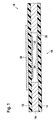
- FIGS. 1 and 2 Such a sensor is shown in FIGS. 1 and 2, with FIG Represents section through an active area of the sensor.
- the sensor comprises a first and a second carrier film 12 and 14 which by means of a spacer 16, for example a double-sided adhesive film, are laminated together.
- a spacer 16 for example a double-sided adhesive film
- the spacer 16 has a recess 20 so that this Area the two carrier films 12 and 14 are spaced apart.
- contact arrangements 22 and 24 arranged between which at Compressing the two carrier foils produces an electrical contact becomes.
- the contact arrangements 22 and 24 can for example Include electrode structures, at least one of the contact arrangements additionally has a layer of a pressure-sensitive material.
- the Contact arrangements are, for example, before laminating the Carrier films in a screen printing process on the corresponding surfaces of the Carrier films applied.
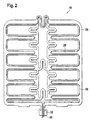
- the Carrier film 12 a heating conductor 28 applied, which extends along the flexible Connection paths of the sensor extends.
- the heating conductor follows thereby advantageous the connecting tracks in such a way that a good Coverage of the heating conductor 28 is reached.
- the two ends 30 of the continuous heating conductor 28 preferably extend up to one Terminal lug 32, which also the electrical connections of the Contact arrangements of the active areas of the seat occupancy sensor. This makes it possible to connect the heating conductor to a heating current source and a Connection of the contact arrangements to an electronic evaluation system by means of a allows single connector element.
- the heating conductor 28 is applied directly to the carrier film 12; he can go to Example applied to the carrier film 12 by means of a screen printing process become.
- the heat conductor has a semiconductor ink, for example on.
- the heating conductor after being applied to the carrier film 12 is preferably covered with a protective layer (not shown).
- This protective layer can advantageously comprise a plastic film or alternatively, a nonwoven layer that can be glued to the carrier film 12.
- the sensor mat for easy detection of a seat occupancy or for Classification of a person sitting in the seat serves this in the general active areas in the area of the side beads of the seat and accordingly also flexible connecting tracks that extend over the side beads extend.
- a simple seat occupancy sensor which is in the generally only extends over the actual seat surface of the seat the sensor has additional flexible strips that extend over the Extend the side beads of the seat.
- Such flexible strips can be simple are punched out of a carrier film of the sensor and are accordingly easy to manufacture.
- the heating conductor then advantageously also extends over these additional sensor strips so that the side beads of the seat be heated. Note that there are none in the additional stripes Active areas of the seat occupancy sensor must be arranged. Farther the flexible strips do not need to be punched out of a sandwich structure it is sufficient that only the carrier film on which the Heating conductor is applied, has such strips.
Landscapes
- Engineering & Computer Science (AREA)
- Mechanical Engineering (AREA)
- Physics & Mathematics (AREA)
- Mathematical Physics (AREA)
- Transportation (AREA)
- Aviation & Aerospace Engineering (AREA)
- Theoretical Computer Science (AREA)
- General Physics & Mathematics (AREA)
- Computer Networks & Wireless Communication (AREA)
- Surface Heating Bodies (AREA)
- Resistance Heating (AREA)
- Seats For Vehicles (AREA)
- Measuring Oxygen Concentration In Cells (AREA)
- Control Of Resistance Heating (AREA)
- Chair Legs, Seat Parts, And Backrests (AREA)
- Fire-Detection Mechanisms (AREA)
- Central Heating Systems (AREA)
- Control Of High-Frequency Heating Circuits (AREA)
- Mattresses And Other Support Structures For Chairs And Beds (AREA)
- Force Measurement Appropriate To Specific Purposes (AREA)
Description
- Fig.1:
- einen Schnitt durch eine Ausgestaltung eines kombinierten Sensor- und Heizelements;
- Fig.2:
- eine Draufsicht auf eine Ausgestaltung eines kombinierten Sensor- und Heizelements.
Claims (12)
- Kombiniertes Sensor- und Heizelement (10), umfassend
eine Sensormatte mit mehreren aktiven Bereichen (18), die untereinander durch flexible Verbindungsstreifen verbunden sind, wobei die flexiblen Verbindungsbahnen zwei zusammenlaminierte Trägerfolien (12, 14) umfassen und wobei in den aktiven Bereichen (18) Kontaktanordnungen (22, 24) auf die Innenseiten der Trägerfolien (12, 14) angeordnet sind, und
einen Heizleiter (28),
dadurch gekennzeichnet, dass der Heizleiter (28) direkt auf eine Außenseite einer der Trägerfolien (12) der flexiblen Verbindungsstreifen der Sensormatte (10) aufgebracht ist. - Kombiniertes Sensor- und Heizelement nach Anspruch 1, dadurch gekennzeichnet dass der Heizleiter (28) durch eine Schutzschicht abgedeckt ist.
- Kombiniertes Sensor- und Heizelement nach Anspruch 2, dadurch gekennzeichnet dass die Schutzschicht eine Kunststofffolie aufweist.
- Kombiniertes Sensor- und Heizelement nach Anspruch 2, dadurch gekennzeichnet, dass die Schutzschicht eine Vliesstofflage aufweist.
- Kombiniertes Sensor- und Heizelement nach einem der Ansprüche 2 bis 4, dadurch gekennzeichnet dass die Schutzschicht auf die flexiblen Verbindungsstreifen der Sensormatte auflaminiert ist.
- Kombiniertes Sensor- und Heizelement nach einem der Ansprüche 1 bis 5, dadurch gekennzeichnet, dass der Heizleiter (28) auf die flexiblen Verbindungsstreifen der Sensormatte aufgeklebt ist.
- Kombiniertes Sensor- und Heizelement nach einem der Ansprüche 1 bis 5, dadurch gekennzeichnet, dass der Heizleiter (28) auf die flexiblen Verbindungsstreifen der Sensormatte aufgedruckt ist.
- Kombiniertes Sensor- und Heizelement nach Anspruch 7, dadurch gekennzeichnet, dass der Heizleiter (28) eine Halbleitertinte aufweist.
- Kombiniertes Sensor- und Heizelement nach einem der vorhergehenden Ansprüche, dadurch gekennzeichnet, dass der Heizleiter (28) ein Widerstandsmaterial mit einem positiven Temperaturkoeffizienten aufweist.
- Kombiniertes Sensor- und Heizelement nach einem der vorhergehenden Ansprüche, dadurch gekennzeichnet, dass elektrische Anschlüsse der Sensormatte und elektrische Anschlüsse des Heizleiters (28) an einer gleichen Anschlussfahne des kombinierten Sensor- und Heizelementes (10) angeordnet sind.
- Kombiniertes Sensor- und Heizelement nach Anspruch 10, dadurch gekennzeichnet, dass die Sensormatte und der Heizleiter (28) an eine kombinierte Auswerte- und Versorgungsschaltung anschließbar ist
- Fahrzeugsitz umfassend ein kombiniertes Sensor- und Heizelement nach einem der Ansprüche 1 bis 11.
Applications Claiming Priority (3)
| Application Number | Priority Date | Filing Date | Title |
|---|---|---|---|
| LU90583 | 2000-05-17 | ||
| LU90583A LU90583B1 (de) | 2000-05-17 | 2000-05-17 | Kombiniertes Sensor-und Heizelement |
| PCT/EP2001/004549 WO2001089267A1 (de) | 2000-05-17 | 2001-04-23 | Kombiniertes sensor- und heizelement |
Publications (2)
| Publication Number | Publication Date |
|---|---|
| EP1283005A1 EP1283005A1 (de) | 2003-02-12 |
| EP1283005B1 true EP1283005B1 (de) | 2004-03-24 |
Family
ID=19731903
Family Applications (1)
| Application Number | Title | Priority Date | Filing Date |
|---|---|---|---|
| EP01940354A Expired - Lifetime EP1283005B1 (de) | 2000-05-17 | 2001-04-23 | Kombiniertes sensor- und heizelement |
Country Status (8)
| Country | Link |
|---|---|
| US (1) | US6906293B2 (de) |
| EP (1) | EP1283005B1 (de) |
| JP (1) | JP2003533311A (de) |
| AT (1) | ATE262771T1 (de) |
| DE (1) | DE50101783D1 (de) |
| ES (1) | ES2218421T3 (de) |
| LU (1) | LU90583B1 (de) |
| WO (1) | WO2001089267A1 (de) |
Cited By (3)
| Publication number | Priority date | Publication date | Assignee | Title |
|---|---|---|---|---|
| US7134715B1 (en) | 2000-07-17 | 2006-11-14 | Kongsberg Automotive Ab | Vehicle seat heating arrangement |
| US7708101B2 (en) | 2005-01-24 | 2010-05-04 | F.S. Fehrer Automotive Gmbh | Motor vehicle seat having occupant detector |
| CN106062521A (zh) * | 2014-02-17 | 2016-10-26 | Iee国际电子工程股份公司 | 乘员传感器及具有这种乘员传感器的座椅 |
Families Citing this family (60)
| Publication number | Priority date | Publication date | Assignee | Title |
|---|---|---|---|---|
| US6884965B2 (en) * | 1999-01-25 | 2005-04-26 | Illinois Tool Works Inc. | Flexible heater device |
| US7202444B2 (en) * | 1999-01-25 | 2007-04-10 | Illinois Tool Works Inc. | Flexible seat heater |
| LU90771B1 (fr) * | 2001-05-08 | 2002-11-11 | Iee Sarl | Dispositif de détection pour siège automobile |
| DE50311249D1 (de) * | 2002-10-23 | 2009-04-16 | Braincom Ag | Flächenheizung, verfahren zu deren herstellung und heizbarer gegenstand sowie sitzbelegungserkennung, sitz damit und sitzbelegungserkennungsverfahren |
| US7306283B2 (en) | 2002-11-21 | 2007-12-11 | W.E.T. Automotive Systems Ag | Heater for an automotive vehicle and method of forming same |
| FR2852273B1 (fr) * | 2003-03-11 | 2005-05-27 | Element de siege de vehicule muni d'un systeme de detection et siege de vehicule equipe d'un tel element de siege | |
| GB2405222B (en) * | 2003-08-21 | 2007-10-17 | Ford Global Technologies Llc F | Method for controlling the heating of a motor vehicle seat |
| DE10358793A1 (de) | 2003-12-12 | 2005-08-04 | Carl Freudenberg Kg | Kombiniertes Sensor- und Heizelement |
| DE10358791A1 (de) * | 2003-12-12 | 2005-08-04 | Carl Freudenberg Kg | Kombiniertes Sensor- und Heizelement |
| WO2005089019A2 (de) * | 2004-03-08 | 2005-09-22 | W.E.T. Automotive Systems Ag | Flächiges heizelement |
| US7362225B2 (en) * | 2004-11-24 | 2008-04-22 | Elesys North America Inc. | Flexible occupant sensor and method of use |
| EP1821088A1 (de) * | 2006-02-16 | 2007-08-22 | IEE International Electronics & Engineering S.A.R.L. | Druckempfindliche Matte |
| US20070241895A1 (en) * | 2006-04-13 | 2007-10-18 | Morgan Kelvin L | Noise reduction for flexible sensor material in occupant detection |
| DE102006031899B3 (de) * | 2006-04-20 | 2007-06-21 | W.E.T. Automotive Systems Ag | Einrichtungen zum Klimatisieren, zum Detektieren und zum Sitzen |
| US7500536B2 (en) | 2006-09-27 | 2009-03-10 | Illinois Tool Works Inc. | Seat heater with occupant sensor |
| US7598881B2 (en) * | 2006-10-18 | 2009-10-06 | Elesys North America, Inc. | Sensor and circuit configuration for occupant detection |
| CL2008000704A1 (es) * | 2007-03-12 | 2008-09-12 | Lma Medical Innovations Ltd | Procedimiento para calentar un fluido intravenoso que comprende unir un elemento calefactor, electricamente resistor, a una linea suministradora de fluido, acoplar electricamente una fuente de energia al elemento calefactor, electricamente resistor; |
| US20090008377A1 (en) * | 2007-07-05 | 2009-01-08 | Lear Corporation | Occupant sensing heat mat |
| KR101168601B1 (ko) | 2007-10-18 | 2012-07-30 | 베.에.테. 오토모티브 시스템스 아게 | 전기 전도성 장치 |
| EP2062771A1 (de) * | 2007-11-21 | 2009-05-27 | Delphi Technologies, Inc. | Sitzheizungs- und Sicherheitsgurtwarnsystem |
| US20090301116A1 (en) * | 2008-06-09 | 2009-12-10 | Lear Corporation | Climate controlling system |
| JP5415028B2 (ja) * | 2008-06-26 | 2014-02-12 | パナソニックヘルスケア株式会社 | 圧力センサ付敷物、及び健康管理装置 |
| DE102009059114A1 (de) | 2009-12-18 | 2011-06-22 | Continental Automotive GmbH, 30165 | Matte mit einem Heizelement und mindestens einer Elektrode |
| DE102011014516A1 (de) | 2010-04-06 | 2012-05-10 | W.E.T. Automotive Systems Ag | Multifunktionsprodukt |
| DE102011105675A1 (de) | 2010-07-15 | 2012-01-19 | W.E.T. Automotive Systems Ag | Elektrische Leitung |
| US9191997B2 (en) | 2010-10-19 | 2015-11-17 | Gentherm Gmbh | Electrical conductor |
| DE102012000977A1 (de) | 2011-04-06 | 2012-10-11 | W.E.T. Automotive Systems Ag | Heizeinrichtung für komplex geformte Oberflächen |
| DE102012009295A1 (de) | 2011-05-12 | 2013-01-03 | W.E.T. Automotive Systems Ag | Verfahren und Vorrichtung zur Bereitstellung von Wärme für einen Fahrzeugsitz |
| DE202011109990U1 (de) | 2011-09-14 | 2012-12-17 | W.E.T. Automotive Systems Ag | Temperier-Einrichtung |
| USD661794S1 (en) | 2011-09-21 | 2012-06-12 | W.E.T. Automotive System, Ltd | Flexible support sheet for a heating element |
| USD661793S1 (en) | 2011-09-21 | 2012-06-12 | W.E.T. Automotive Systems, Ltd | Flexible support sheet for a heating element |
| USD670372S1 (en) * | 2011-10-10 | 2012-11-06 | Applied Materials, Inc. | Heater plate and heater element assembly |
| LU91923B1 (en) * | 2011-12-21 | 2013-06-24 | Iee Sarl | Occupancy sensor for occupiable item e.g. seat or bed |
| US10201039B2 (en) | 2012-01-20 | 2019-02-05 | Gentherm Gmbh | Felt heater and method of making |
| JP5895593B2 (ja) * | 2012-02-29 | 2016-03-30 | 日産自動車株式会社 | 布状圧力センサーヒーター |
| DE102013006410A1 (de) | 2012-06-18 | 2013-12-19 | W.E.T. Automotive Systems Ag | Flächengebilde mit elektrischer Funktion |
| DE102012017047A1 (de) | 2012-08-29 | 2014-03-06 | W.E.T. Automotive Systems Ag | Elektrische Heizeinrichtung |
| DE102012024903A1 (de) | 2012-12-20 | 2014-06-26 | W.E.T. Automotive Systems Ag | Flächengebilde mit elektrischen Funktionselementen |
| US9408939B2 (en) | 2013-03-15 | 2016-08-09 | Medline Industries, Inc. | Anti-microbial air processor for a personal patient warming apparatus |
| JP6198934B2 (ja) | 2013-05-02 | 2017-09-20 | ジェンサーム ゲーエムベーハー | 耐液加熱エレメント |
| KR102081430B1 (ko) | 2013-05-15 | 2020-02-25 | 젠썸 캐나다 유엘씨 | 콤비네이션 히터 및 센서 |
| DE112014004662T5 (de) | 2013-10-11 | 2016-08-04 | Gentherm Canada Ltd. | Sitzbelegungserkennung mit Heizvorrichtungen |
| US9889809B2 (en) * | 2015-03-06 | 2018-02-13 | Ford Global Technologies, Llc | Vehicle seat thermistor for classifying seat occupant type |
| JP6427056B2 (ja) * | 2015-03-31 | 2018-11-21 | 株式会社タチエス | 座席装置 |
| DE112016004184T5 (de) * | 2015-09-15 | 2018-06-07 | Denso Corporation | Heizvorrichtung |
| JP6432695B2 (ja) * | 2015-12-09 | 2018-12-05 | 株式会社デンソー | ヒータ装置、およびヒータ装置の製造方法 |
| WO2017104343A1 (ja) * | 2015-12-17 | 2017-06-22 | 株式会社デンソー | ヒータ装置 |
| CN105559452A (zh) * | 2016-03-16 | 2016-05-11 | 杨跃龙 | 智能感应安全电热毯 |
| DE202016105638U1 (de) * | 2016-10-08 | 2016-11-03 | Faurecia Autositze Gmbh | Kraftfahrzeuginnenraumanordnung |
| DE102017001097A1 (de) | 2017-02-07 | 2018-08-09 | Gentherm Gmbh | Elektrisch leitfähige Folie |
| US10272807B2 (en) | 2017-05-02 | 2019-04-30 | Ford Global Technologies, Llc | Efficient control of temperature altering systems within a vehicle seating assembly |
| JP7035947B2 (ja) * | 2018-10-09 | 2022-03-15 | 株式会社デンソー | シートヒータ装置 |
| PL3704991T3 (pl) * | 2019-03-05 | 2021-09-13 | Cs Centro Stirling, S.Coop. | Pojemnik na drugie śniadanie |
| DE102019213466A1 (de) * | 2019-09-05 | 2021-03-11 | Audi Ag | Heizeinrichtung für eine Komponente eines Kraftfahrzeugs und Kraftfahrzeug |
| DE102019213463A1 (de) * | 2019-09-05 | 2021-03-11 | Audi Ag | Heizeinrichtung für eine Komponente eines Kraftfahrzeugs und Kraftfahrzeug |
| DE102019213468A1 (de) * | 2019-09-05 | 2021-03-11 | Audi Ag | Komponente eines Kraftfahrzeugs und Kraftfahrzeug |
| DE102019213465A1 (de) * | 2019-09-05 | 2021-03-11 | Audi Ag | Heizeinrichtung für eine Komponente eines Kraftfahrzeugs und Kraftfahrzeug |
| DE102020100226A1 (de) * | 2020-01-08 | 2021-07-08 | Thüringisches Institut für Textil- und Kunststoff-Forschung e. V. Rudolstadt | Elektrische Heizmatte |
| CA3210133A1 (en) | 2021-03-01 | 2022-09-09 | Kody Lee Karschnik | Bed sensors |
| DE102024100266A1 (de) * | 2024-01-05 | 2025-07-10 | Haake Technik Gmbh | Gefalteter Taktiler Sensor |
Family Cites Families (9)
| Publication number | Priority date | Publication date | Assignee | Title |
|---|---|---|---|---|
| US3537053A (en) * | 1966-01-19 | 1970-10-27 | Robertshaw Controls Co | Flexible temperature sensor for motor protection |
| EP0139635A1 (de) * | 1983-04-15 | 1985-05-08 | Ab Mekania-Verken | Heizkissen vorzugsweise für fahrzeugsitze |
| US5835983A (en) * | 1996-09-13 | 1998-11-10 | Sunbeam Products, Inc. | Heating device and method of manufacturing the same |
| DE19717273C1 (de) * | 1997-04-24 | 1998-07-30 | Volkswagen Ag | Vorrichtung mit einem Foliendrucksensor zur Sitzbelegungserkennung für einen Fahrzeugsitz |
| DE19813559C2 (de) * | 1998-03-27 | 2002-10-17 | Siegfried Schoeppner | Heizbarer Sitz für den Außenbereich |
| US5948303A (en) * | 1998-05-04 | 1999-09-07 | Larson; Lynn D. | Temperature control for a bed |
| DE19851979C2 (de) * | 1998-11-11 | 2000-08-31 | Daimler Chrysler Ag | Temperaturfühler für einen klimatisierten Fahrzeugsitz |
| US6195921B1 (en) * | 1999-09-28 | 2001-03-06 | Vinncente Hoa Gia Truong | Virtual intelligence shoe with a podiatric analysis system |
| LU90578B1 (de) * | 2000-05-05 | 2001-11-06 | Iee Sarl | Sensormatte fuer Fahrzeug |
-
2000
- 2000-05-17 LU LU90583A patent/LU90583B1/de active
-
2001
- 2001-04-23 WO PCT/EP2001/004549 patent/WO2001089267A1/de not_active Ceased
- 2001-04-23 ES ES01940354T patent/ES2218421T3/es not_active Expired - Lifetime
- 2001-04-23 JP JP2001585127A patent/JP2003533311A/ja active Pending
- 2001-04-23 AT AT01940354T patent/ATE262771T1/de not_active IP Right Cessation
- 2001-04-23 EP EP01940354A patent/EP1283005B1/de not_active Expired - Lifetime
- 2001-04-23 US US10/276,437 patent/US6906293B2/en not_active Expired - Lifetime
- 2001-04-23 DE DE50101783T patent/DE50101783D1/de not_active Expired - Fee Related
Cited By (5)
| Publication number | Priority date | Publication date | Assignee | Title |
|---|---|---|---|---|
| US7134715B1 (en) | 2000-07-17 | 2006-11-14 | Kongsberg Automotive Ab | Vehicle seat heating arrangement |
| US7708101B2 (en) | 2005-01-24 | 2010-05-04 | F.S. Fehrer Automotive Gmbh | Motor vehicle seat having occupant detector |
| DE102005056882B4 (de) * | 2005-01-24 | 2012-06-14 | F.S. Fehrer Automotive Gmbh | Kraftfahrzeugsitz mit Insassendetektor |
| CN106062521A (zh) * | 2014-02-17 | 2016-10-26 | Iee国际电子工程股份公司 | 乘员传感器及具有这种乘员传感器的座椅 |
| CN106062521B (zh) * | 2014-02-17 | 2019-10-18 | Iee国际电子工程股份公司 | 乘员传感器及具有这种乘员传感器的座椅 |
Also Published As
| Publication number | Publication date |
|---|---|
| ES2218421T3 (es) | 2004-11-16 |
| US20030141983A1 (en) | 2003-07-31 |
| JP2003533311A (ja) | 2003-11-11 |
| US6906293B2 (en) | 2005-06-14 |
| ATE262771T1 (de) | 2004-04-15 |
| WO2001089267A1 (de) | 2001-11-22 |
| DE50101783D1 (de) | 2004-04-29 |
| LU90583B1 (de) | 2001-11-19 |
| EP1283005A1 (de) | 2003-02-12 |
Similar Documents
| Publication | Publication Date | Title |
|---|---|---|
| EP1283005B1 (de) | Kombiniertes sensor- und heizelement | |
| EP1636812B1 (de) | Drucksensor in folienbauweise | |
| EP1279181B1 (de) | Sensormatte für fahrzeugsitz | |
| EP0946926B1 (de) | Kontaktlose chipkarte mit transponderspule | |
| DE69230660T2 (de) | Kabelbaum | |
| EP1692018B1 (de) | Kombiniertes sensor- und heizelement | |
| DE112005000939T5 (de) | Heizelment für ein Fahrzeug und Verfahren zum Formen desselben | |
| DE102006002919A1 (de) | Kapazitiver Sensor und Insassenerfassungssystem | |
| DE202016001419U1 (de) | Kapazitiver Flächensensor | |
| DE8310623U1 (de) | Beschleunigungsgrenzwertschalter | |
| DE69432562T2 (de) | Elektrische anordnung | |
| EP1692003A1 (de) | Kombiniertes sensor- und heizelement | |
| EP2062771A1 (de) | Sitzheizungs- und Sicherheitsgurtwarnsystem | |
| EP1428235A1 (de) | Schaltelement in folienbauweise | |
| WO2000011443A1 (de) | Flächenelektrode für kapazitive erkennungssysteme | |
| DE10057222B4 (de) | Flächenheizelement | |
| EP1833702B2 (de) | Sensormatte mit zwei schaltniveaus | |
| DE102015120550B3 (de) | Verbindungsvorrichtung und verbindungsverfahren | |
| DE202016104021U1 (de) | Sitzbelegungssensoreinheit und Sitz | |
| DE19752628C2 (de) | Druckempfindlicher Schalter | |
| DE102013206450B4 (de) | Sitzbelegungssensor und Herstellungsverfahren | |
| DE102004055469A1 (de) | Sensor mit verformungsabhängigem Widerstandswert | |
| AT504406B1 (de) | Messvorrichtung | |
| DE102017216057A1 (de) | Thermoelektrisches Gewebe | |
| DE102007016119B4 (de) | Sitzbelegungssensor für die Ansteuerung eines Insassenschutzsystems in einem Kraftfahrzeug |
Legal Events
| Date | Code | Title | Description |
|---|---|---|---|
| PUAI | Public reference made under article 153(3) epc to a published international application that has entered the european phase |
Free format text: ORIGINAL CODE: 0009012 |
|
| 17P | Request for examination filed |
Effective date: 20021021 |
|
| AK | Designated contracting states |
Designated state(s): AT BE CH CY DE DK ES FI FR GB GR IE IT LI LU MC NL PT SE TR |
|
| 17Q | First examination report despatched |
Effective date: 20030227 |
|
| RAP1 | Party data changed (applicant data changed or rights of an application transferred) |
Owner name: IEE INTERNATIONAL ELECTRONICS & ENGINEERING S. |
|
| GRAP | Despatch of communication of intention to grant a patent |
Free format text: ORIGINAL CODE: EPIDOSNIGR1 |
|
| GRAS | Grant fee paid |
Free format text: ORIGINAL CODE: EPIDOSNIGR3 |
|
| GRAA | (expected) grant |
Free format text: ORIGINAL CODE: 0009210 |
|
| AK | Designated contracting states |
Kind code of ref document: B1 Designated state(s): AT BE CH CY DE DK ES FI FR GB GR IE IT LI LU MC NL PT SE TR |
|
| PG25 | Lapsed in a contracting state [announced via postgrant information from national office to epo] |
Ref country code: TR Free format text: LAPSE BECAUSE OF FAILURE TO SUBMIT A TRANSLATION OF THE DESCRIPTION OR TO PAY THE FEE WITHIN THE PRESCRIBED TIME-LIMIT Effective date: 20040324 Ref country code: NL Free format text: LAPSE BECAUSE OF FAILURE TO SUBMIT A TRANSLATION OF THE DESCRIPTION OR TO PAY THE FEE WITHIN THE PRESCRIBED TIME-LIMIT Effective date: 20040324 Ref country code: IE Free format text: LAPSE BECAUSE OF FAILURE TO SUBMIT A TRANSLATION OF THE DESCRIPTION OR TO PAY THE FEE WITHIN THE PRESCRIBED TIME-LIMIT Effective date: 20040324 Ref country code: FI Free format text: LAPSE BECAUSE OF FAILURE TO SUBMIT A TRANSLATION OF THE DESCRIPTION OR TO PAY THE FEE WITHIN THE PRESCRIBED TIME-LIMIT Effective date: 20040324 Ref country code: CY Free format text: LAPSE BECAUSE OF FAILURE TO SUBMIT A TRANSLATION OF THE DESCRIPTION OR TO PAY THE FEE WITHIN THE PRESCRIBED TIME-LIMIT Effective date: 20040324 |
|
| REG | Reference to a national code |
Ref country code: GB Ref legal event code: FG4D Free format text: NOT ENGLISH |
|
| REG | Reference to a national code |
Ref country code: CH Ref legal event code: EP |
|
| REG | Reference to a national code |
Ref country code: IE Ref legal event code: FG4D Free format text: GERMAN |
|
| PG25 | Lapsed in a contracting state [announced via postgrant information from national office to epo] |
Ref country code: LU Free format text: LAPSE BECAUSE OF NON-PAYMENT OF DUE FEES Effective date: 20040423 Ref country code: AT Free format text: LAPSE BECAUSE OF NON-PAYMENT OF DUE FEES Effective date: 20040423 |
|
| REF | Corresponds to: |
Ref document number: 50101783 Country of ref document: DE Date of ref document: 20040429 Kind code of ref document: P |
|
| PG25 | Lapsed in a contracting state [announced via postgrant information from national office to epo] |
Ref country code: MC Free format text: LAPSE BECAUSE OF NON-PAYMENT OF DUE FEES Effective date: 20040430 Ref country code: BE Free format text: LAPSE BECAUSE OF NON-PAYMENT OF DUE FEES Effective date: 20040430 |
|
| GBT | Gb: translation of ep patent filed (gb section 77(6)(a)/1977) |
Effective date: 20040526 |
|
| PG25 | Lapsed in a contracting state [announced via postgrant information from national office to epo] |
Ref country code: GR Free format text: LAPSE BECAUSE OF FAILURE TO SUBMIT A TRANSLATION OF THE DESCRIPTION OR TO PAY THE FEE WITHIN THE PRESCRIBED TIME-LIMIT Effective date: 20040624 Ref country code: DK Free format text: LAPSE BECAUSE OF FAILURE TO SUBMIT A TRANSLATION OF THE DESCRIPTION OR TO PAY THE FEE WITHIN THE PRESCRIBED TIME-LIMIT Effective date: 20040624 |
|
| REG | Reference to a national code |
Ref country code: SE Ref legal event code: TRGR |
|
| NLV1 | Nl: lapsed or annulled due to failure to fulfill the requirements of art. 29p and 29m of the patents act | ||
| REG | Reference to a national code |
Ref country code: IE Ref legal event code: FD4D |
|
| BERE | Be: lapsed |
Owner name: IEE INTERNATIONAL ELECTRONICS & ENGINEERING S.A. Effective date: 20040430 |
|
| ET | Fr: translation filed | ||
| REG | Reference to a national code |
Ref country code: ES Ref legal event code: FG2A Ref document number: 2218421 Country of ref document: ES Kind code of ref document: T3 |
|
| PLBE | No opposition filed within time limit |
Free format text: ORIGINAL CODE: 0009261 |
|
| STAA | Information on the status of an ep patent application or granted ep patent |
Free format text: STATUS: NO OPPOSITION FILED WITHIN TIME LIMIT |
|
| 26N | No opposition filed |
Effective date: 20041228 |
|
| PGFP | Annual fee paid to national office [announced via postgrant information from national office to epo] |
Ref country code: GB Payment date: 20050321 Year of fee payment: 5 |
|
| PGFP | Annual fee paid to national office [announced via postgrant information from national office to epo] |
Ref country code: SE Payment date: 20050420 Year of fee payment: 5 |
|
| PG25 | Lapsed in a contracting state [announced via postgrant information from national office to epo] |
Ref country code: LI Free format text: LAPSE BECAUSE OF NON-PAYMENT OF DUE FEES Effective date: 20050430 Ref country code: CH Free format text: LAPSE BECAUSE OF NON-PAYMENT OF DUE FEES Effective date: 20050430 |
|
| PGFP | Annual fee paid to national office [announced via postgrant information from national office to epo] |
Ref country code: ES Payment date: 20050512 Year of fee payment: 5 |
|
| REG | Reference to a national code |
Ref country code: CH Ref legal event code: PL |
|
| PGFP | Annual fee paid to national office [announced via postgrant information from national office to epo] |
Ref country code: FR Payment date: 20060314 Year of fee payment: 6 |
|
| PG25 | Lapsed in a contracting state [announced via postgrant information from national office to epo] |
Ref country code: GB Free format text: LAPSE BECAUSE OF NON-PAYMENT OF DUE FEES Effective date: 20060423 |
|
| PG25 | Lapsed in a contracting state [announced via postgrant information from national office to epo] |
Ref country code: SE Free format text: LAPSE BECAUSE OF NON-PAYMENT OF DUE FEES Effective date: 20060424 Ref country code: ES Free format text: LAPSE BECAUSE OF NON-PAYMENT OF DUE FEES Effective date: 20060424 |
|
| PGFP | Annual fee paid to national office [announced via postgrant information from national office to epo] |
Ref country code: IT Payment date: 20060430 Year of fee payment: 6 |
|
| EUG | Se: european patent has lapsed | ||
| GBPC | Gb: european patent ceased through non-payment of renewal fee |
Effective date: 20060423 |
|
| PGFP | Annual fee paid to national office [announced via postgrant information from national office to epo] |
Ref country code: DE Payment date: 20070213 Year of fee payment: 7 |
|
| REG | Reference to a national code |
Ref country code: ES Ref legal event code: FD2A Effective date: 20060424 |
|
| PG25 | Lapsed in a contracting state [announced via postgrant information from national office to epo] |
Ref country code: PT Free format text: LAPSE BECAUSE OF NON-PAYMENT OF DUE FEES Effective date: 20040824 |
|
| PG25 | Lapsed in a contracting state [announced via postgrant information from national office to epo] |
Ref country code: FR Free format text: LAPSE BECAUSE OF NON-PAYMENT OF DUE FEES Effective date: 20070430 |
|
| PG25 | Lapsed in a contracting state [announced via postgrant information from national office to epo] |
Ref country code: DE Free format text: LAPSE BECAUSE OF NON-PAYMENT OF DUE FEES Effective date: 20081101 |
|
| PG25 | Lapsed in a contracting state [announced via postgrant information from national office to epo] |
Ref country code: IT Free format text: LAPSE BECAUSE OF NON-PAYMENT OF DUE FEES Effective date: 20070423 |