EP1283005B1 - Combined sensor and heating element - Google Patents
Combined sensor and heating element Download PDFInfo
- Publication number
- EP1283005B1 EP1283005B1 EP01940354A EP01940354A EP1283005B1 EP 1283005 B1 EP1283005 B1 EP 1283005B1 EP 01940354 A EP01940354 A EP 01940354A EP 01940354 A EP01940354 A EP 01940354A EP 1283005 B1 EP1283005 B1 EP 1283005B1
- Authority
- EP
- European Patent Office
- Prior art keywords
- sensor
- heating element
- element according
- combined sensor
- heat conductor
- Prior art date
- Legal status (The legal status is an assumption and is not a legal conclusion. Google has not performed a legal analysis and makes no representation as to the accuracy of the status listed.)
- Expired - Lifetime
Links
- 238000010438 heat treatment Methods 0.000 title claims abstract description 58
- 239000004020 conductor Substances 0.000 claims abstract description 32
- 239000011888 foil Substances 0.000 claims abstract description 9
- 239000011241 protective layer Substances 0.000 claims description 8
- 239000000463 material Substances 0.000 claims description 6
- 239000010410 layer Substances 0.000 claims description 5
- 238000011156 evaluation Methods 0.000 claims description 4
- 239000004065 semiconductor Substances 0.000 claims description 3
- 239000004744 fabric Substances 0.000 claims 1
- 239000011324 bead Substances 0.000 description 6
- 238000004519 manufacturing process Methods 0.000 description 6
- 238000001514 detection method Methods 0.000 description 3
- 238000000034 method Methods 0.000 description 3
- 238000007650 screen-printing Methods 0.000 description 3
- 239000002985 plastic film Substances 0.000 description 2
- 229920006255 plastic film Polymers 0.000 description 2
- 125000006850 spacer group Chemical group 0.000 description 2
- 239000002313 adhesive film Substances 0.000 description 1
- 238000010276 construction Methods 0.000 description 1
- 230000003111 delayed effect Effects 0.000 description 1
- 230000000694 effects Effects 0.000 description 1
- 238000009434 installation Methods 0.000 description 1
- 238000010030 laminating Methods 0.000 description 1
Images
Classifications
-
- G—PHYSICS
- G01—MEASURING; TESTING
- G01G—WEIGHING
- G01G19/00—Weighing apparatus or methods adapted for special purposes not provided for in the preceding groups
- G01G19/40—Weighing apparatus or methods adapted for special purposes not provided for in the preceding groups with provisions for indicating, recording, or computing price or other quantities dependent on the weight
- G01G19/413—Weighing apparatus or methods adapted for special purposes not provided for in the preceding groups with provisions for indicating, recording, or computing price or other quantities dependent on the weight using electromechanical or electronic computing means
- G01G19/414—Weighing apparatus or methods adapted for special purposes not provided for in the preceding groups with provisions for indicating, recording, or computing price or other quantities dependent on the weight using electromechanical or electronic computing means using electronic computing means only
- G01G19/4142—Weighing apparatus or methods adapted for special purposes not provided for in the preceding groups with provisions for indicating, recording, or computing price or other quantities dependent on the weight using electromechanical or electronic computing means using electronic computing means only for controlling activation of safety devices, e.g. airbag systems
-
- B—PERFORMING OPERATIONS; TRANSPORTING
- B60—VEHICLES IN GENERAL
- B60N—SEATS SPECIALLY ADAPTED FOR VEHICLES; VEHICLE PASSENGER ACCOMMODATION NOT OTHERWISE PROVIDED FOR
- B60N2/00—Seats specially adapted for vehicles; Arrangement or mounting of seats in vehicles
- B60N2/002—Seats provided with an occupancy detection means mounted therein or thereon
-
- B—PERFORMING OPERATIONS; TRANSPORTING
- B60—VEHICLES IN GENERAL
- B60N—SEATS SPECIALLY ADAPTED FOR VEHICLES; VEHICLE PASSENGER ACCOMMODATION NOT OTHERWISE PROVIDED FOR
- B60N2/00—Seats specially adapted for vehicles; Arrangement or mounting of seats in vehicles
- B60N2/56—Heating or ventilating devices
- B60N2/5678—Heating or ventilating devices characterised by electrical systems
- B60N2/5685—Resistance
-
- B—PERFORMING OPERATIONS; TRANSPORTING
- B60—VEHICLES IN GENERAL
- B60R—VEHICLES, VEHICLE FITTINGS, OR VEHICLE PARTS, NOT OTHERWISE PROVIDED FOR
- B60R21/00—Arrangements or fittings on vehicles for protecting or preventing injuries to occupants or pedestrians in case of accidents or other traffic risks
- B60R21/01—Electrical circuits for triggering passive safety arrangements, e.g. airbags, safety belt tighteners, in case of vehicle accidents or impending vehicle accidents
- B60R21/015—Electrical circuits for triggering passive safety arrangements, e.g. airbags, safety belt tighteners, in case of vehicle accidents or impending vehicle accidents including means for detecting the presence or position of passengers, passenger seats or child seats, and the related safety parameters therefor, e.g. speed or timing of airbag inflation in relation to occupant position or seat belt use
- B60R21/01512—Passenger detection systems
- B60R21/01516—Passenger detection systems using force or pressure sensing means
-
- B—PERFORMING OPERATIONS; TRANSPORTING
- B60—VEHICLES IN GENERAL
- B60R—VEHICLES, VEHICLE FITTINGS, OR VEHICLE PARTS, NOT OTHERWISE PROVIDED FOR
- B60R21/00—Arrangements or fittings on vehicles for protecting or preventing injuries to occupants or pedestrians in case of accidents or other traffic risks
- B60R21/01—Electrical circuits for triggering passive safety arrangements, e.g. airbags, safety belt tighteners, in case of vehicle accidents or impending vehicle accidents
- B60R21/015—Electrical circuits for triggering passive safety arrangements, e.g. airbags, safety belt tighteners, in case of vehicle accidents or impending vehicle accidents including means for detecting the presence or position of passengers, passenger seats or child seats, and the related safety parameters therefor, e.g. speed or timing of airbag inflation in relation to occupant position or seat belt use
- B60R21/01512—Passenger detection systems
- B60R21/0153—Passenger detection systems using field detection presence sensors
- B60R21/0154—Passenger detection systems using field detection presence sensors in combination with seat heating
-
- H—ELECTRICITY
- H05—ELECTRIC TECHNIQUES NOT OTHERWISE PROVIDED FOR
- H05B—ELECTRIC HEATING; ELECTRIC LIGHT SOURCES NOT OTHERWISE PROVIDED FOR; CIRCUIT ARRANGEMENTS FOR ELECTRIC LIGHT SOURCES, IN GENERAL
- H05B3/00—Ohmic-resistance heating
- H05B3/20—Heating elements having extended surface area substantially in a two-dimensional plane, e.g. plate-heater
- H05B3/34—Heating elements having extended surface area substantially in a two-dimensional plane, e.g. plate-heater flexible, e.g. heating nets or webs
-
- H—ELECTRICITY
- H05—ELECTRIC TECHNIQUES NOT OTHERWISE PROVIDED FOR
- H05B—ELECTRIC HEATING; ELECTRIC LIGHT SOURCES NOT OTHERWISE PROVIDED FOR; CIRCUIT ARRANGEMENTS FOR ELECTRIC LIGHT SOURCES, IN GENERAL
- H05B2203/00—Aspects relating to Ohmic resistive heating covered by group H05B3/00
- H05B2203/013—Heaters using resistive films or coatings
-
- H—ELECTRICITY
- H05—ELECTRIC TECHNIQUES NOT OTHERWISE PROVIDED FOR
- H05B—ELECTRIC HEATING; ELECTRIC LIGHT SOURCES NOT OTHERWISE PROVIDED FOR; CIRCUIT ARRANGEMENTS FOR ELECTRIC LIGHT SOURCES, IN GENERAL
- H05B2203/00—Aspects relating to Ohmic resistive heating covered by group H05B3/00
- H05B2203/029—Heaters specially adapted for seat warmers
Definitions
- the present invention relates to a combined sensor and heating element, especially for use in a vehicle seat.
- Such seat occupancy sensors often include a sensor mat with multiple pressure sensitive areas are interconnected by flexible connecting strips.
- the Sensor mat is integrated into the vehicle seat in such a way that the pressure-sensitive Areas are distributed over the seat of the vehicle seat.
- Such a seat heater generally comprises a heating mat made of an in two nonwoven layers embedded heating conductor. Such a heating mat will also integrated into the seat of the vehicle seat, so that the heating conductor is in the extends substantially over the entire seat of the vehicle seat.
- the document DE-A-197 17 273 describes a combined sensor and Heating element.
- the sensor element is made of two carrier films laminated together constructed, between which contact arrangements are arranged.
- the Contact arrangements are as depending on the functional mode of the switching element Heat conductor or used as an electrode arrangement for seat occupancy detection.
- the object of the present invention is therefore a simplified to propose a combined sensor and heating element.
- this object is achieved by a combined sensor and Heating element, with a sensor mat with several active areas are interconnected by flexible connecting strips, and one Heating conductor, the heating conductor directly on the flexible connecting strips of the Sensor mat is applied.
- the heating conductor is not separately in a manageable fleece laminate embedded, which is then fixed on the sensor mat.
- the production of such a combined sensor and heating element therefore requires significantly fewer individual steps than manufacturing conventional combination elements.
- the cost of materials for the Production of the functional element according to the invention less than this conventional functional elements is the case.
- the combined sensor and The heating element of the present invention therefore represents one particular simple and inexpensive combination element.
- the active areas of the sensor mat are pressure sensitive May include areas, i. H. that for example the electrical Properties of the active areas depending on the on the sensor Change the weight you exercise. In another embodiment, you can the active areas also include simple switching elements that only between two states such as "occupied” and "not occupied” differ. In addition, it is irrelevant to the present invention whether the sensor function of the sensor and heating element according to the invention easy detection of a seat occupancy or to classify one in the Serves seated person. In other words, the sensor mat can both a simple seat occupancy sensor and a sensor for Display or record a pressure profile.
- the heat conductor is a Protective layer covered.
- This protective layer can, for example Have plastic film or a nonwoven layer, preferably on the flexible connecting strip of the sensor mat is laminated on.
- the heating conductor itself can be connected to the flexible connecting strips Sensor mat can be glued or printed on.
- the Heat conductor for example, a semiconductor ink, which in one Screen printing process is applied to the connecting webs.
- the heating conductor has Resistance material with a positive temperature coefficient.
- Resistance materials have a higher one at high temperatures electrical resistance than at low temperatures. At a suitable material selection this effect can limit the heating current be exploited so that an expensive downstream Temperature control for the heating element can be omitted.
- the electrical connections of the sensor mat and the electrical connections of the heating conductor are preferably on the same connection lug combined sensor and heating element arranged. This will create a Contacting the two separate functions by a single Connector element enables and thus the later assembly essential simplified.
- the two can be separated Functional elements, for example to common electronics be connected. This electronics then serves both to evaluate the Sensor mat as well as the supply and power control of the heating mat. An intelligent control can prevent, for example, that the Seat heating is switched on when the corresponding seat is not occupied.
- Seat occupancy sensors or sensors for recording or evaluating a Seat profiles are often used as pressure-sensitive surface sensors in foil construction built up.
- Such a seat occupancy sensor generally comprises one Large number of active areas, which are distributed over a certain area and are interconnected by flexible connecting paths of the sensor.
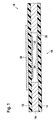
- FIGS. 1 and 2 Such a sensor is shown in FIGS. 1 and 2, with FIG Represents section through an active area of the sensor.
- the sensor comprises a first and a second carrier film 12 and 14 which by means of a spacer 16, for example a double-sided adhesive film, are laminated together.
- a spacer 16 for example a double-sided adhesive film
- the spacer 16 has a recess 20 so that this Area the two carrier films 12 and 14 are spaced apart.
- contact arrangements 22 and 24 arranged between which at Compressing the two carrier foils produces an electrical contact becomes.
- the contact arrangements 22 and 24 can for example Include electrode structures, at least one of the contact arrangements additionally has a layer of a pressure-sensitive material.
- the Contact arrangements are, for example, before laminating the Carrier films in a screen printing process on the corresponding surfaces of the Carrier films applied.
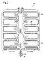
- the Carrier film 12 a heating conductor 28 applied, which extends along the flexible Connection paths of the sensor extends.
- the heating conductor follows thereby advantageous the connecting tracks in such a way that a good Coverage of the heating conductor 28 is reached.
- the two ends 30 of the continuous heating conductor 28 preferably extend up to one Terminal lug 32, which also the electrical connections of the Contact arrangements of the active areas of the seat occupancy sensor. This makes it possible to connect the heating conductor to a heating current source and a Connection of the contact arrangements to an electronic evaluation system by means of a allows single connector element.
- the heating conductor 28 is applied directly to the carrier film 12; he can go to Example applied to the carrier film 12 by means of a screen printing process become.
- the heat conductor has a semiconductor ink, for example on.
- the heating conductor after being applied to the carrier film 12 is preferably covered with a protective layer (not shown).
- This protective layer can advantageously comprise a plastic film or alternatively, a nonwoven layer that can be glued to the carrier film 12.
- the sensor mat for easy detection of a seat occupancy or for Classification of a person sitting in the seat serves this in the general active areas in the area of the side beads of the seat and accordingly also flexible connecting tracks that extend over the side beads extend.
- a simple seat occupancy sensor which is in the generally only extends over the actual seat surface of the seat the sensor has additional flexible strips that extend over the Extend the side beads of the seat.
- Such flexible strips can be simple are punched out of a carrier film of the sensor and are accordingly easy to manufacture.
- the heating conductor then advantageously also extends over these additional sensor strips so that the side beads of the seat be heated. Note that there are none in the additional stripes Active areas of the seat occupancy sensor must be arranged. Farther the flexible strips do not need to be punched out of a sandwich structure it is sufficient that only the carrier film on which the Heating conductor is applied, has such strips.
Abstract
Description
Die vorliegende Erfindung betrifft ein kombiniertes Sensor- und Heizelement, insbesondere zum Einsatz in einem Fahrzeugsitz.The present invention relates to a combined sensor and heating element, especially for use in a vehicle seat.
Moderne Fahrzeuge werden immer häufiger z.B. mit sogenannten Sitzbelegungssensoren ausgestattet, die bei einem Unfall ein Auslösen des einem bestimmten Fahrzeugsitzes zugeordneten Airbags verhindern, falls der entsprechende Fahrzeugsitz nicht belegt ist. Solche Sitzbelegungssensoren umfassen häufig eine Sensormatte mit mehreren drucksensiblen Bereichen, die untereinander durch flexible Verbindungsstreifen verbunden sind. Die Sensormatte wird derart in den Fahrzeugsitz integriert, dass die drucksensiblen Bereiche über die Sitzfläche des Fahrzeugsitzes verteilt sind.Modern vehicles are becoming increasingly common e.g. with so-called Seat occupancy sensors equipped that trigger the prevent airbags associated with a particular vehicle seat if the corresponding vehicle seat is not occupied. Such seat occupancy sensors often include a sensor mat with multiple pressure sensitive areas are interconnected by flexible connecting strips. The Sensor mat is integrated into the vehicle seat in such a way that the pressure-sensitive Areas are distributed over the seat of the vehicle seat.
Die gesteigerten Komfortansprüche der Verbraucher führen überdies dazu, dass immer mehr Fahrzeugsitze mit einer Sitzheizung ausgestattet werden. Eine solche Sitzheizung umfasst im allgemeinen eine Heizmatte aus einem in zwei Vliesstofflagen eingebetteten Heizleiter. Auch eine solche Heizmatte wird in die Sitzfläche des Fahrzeugsitzes integriert, so dass sich der Heizleiter im wesentlichen über die gesamte Sitzfläche des Fahrzeugsitzes erstreckt.The increased comfort requirements of consumers also lead to that more and more vehicle seats are equipped with seat heating. Such a seat heater generally comprises a heating mat made of an in two nonwoven layers embedded heating conductor. Such a heating mat will also integrated into the seat of the vehicle seat, so that the heating conductor is in the extends substantially over the entire seat of the vehicle seat.
Bei Fahrzeugsitzen, die sowohl mit einem Sitzbelegungssensor als auch mit einer Sitzheizung ausgestattet werden, werden die Sensormatte und die Heizmatte vor dem Einbau in den Sitz zu einem kombinierten Sensor- und Heizelement zusammengefügt. Die Herstellung eines solchen kombinierten Sensor- und Heizelementes ist jedoch verhältnismäßig aufwendig, da die beiden Funktionselemente zunächst getrennt hergestellt werden und anschließend aufeinander fixiert werden müssen. For vehicle seats with both a seat occupancy sensor and a seat heater, the sensor mat and the Heating mat before installation in the seat to a combined sensor and Heating element put together. The manufacture of such a combined Sensor and heating element is relatively expensive, however, because the two functional elements are initially manufactured separately and then have to be fixed to each other.
Das Dokument DE-A-197 17 273 beschreibt ein kombiniertes Sensor- und Heizelement. Das Sensorelement ist aus zwei zusammenlaminierten Trägerfolien aufgebaut, zwischen denen Kontaktanordnungen angeordnet sind. Die Kontaktanordnungen werden je nach Funktionsmodus des Schaltelementes als Heizleiter oder als Elektrodenanordnung zur Sitzbelegungserkennung benutzt. The document DE-A-197 17 273 describes a combined sensor and Heating element. The sensor element is made of two carrier films laminated together constructed, between which contact arrangements are arranged. The Contact arrangements are as depending on the functional mode of the switching element Heat conductor or used as an electrode arrangement for seat occupancy detection.
Aufgabe der vorliegenden Erfindung ist es folglich, ein vereinfachtes kombiniertes Sensor- und Heizelement vorzuschlagen.The object of the present invention is therefore a simplified to propose a combined sensor and heating element.
Diese Aufgabe wird erfindungsgemäß gelöst durch ein kombiniertes Sensorund Heizelement, mit einer Sensormatte mit mehreren aktiven Bereichen, die untereinander durch flexible Verbindungsstreifen verbunden sind, und einem Heizleiter, wobei der Heizleiter direkt auf die flexiblen Verbindungsstreifen der Sensormatte aufgebracht ist. Bei diesem Sensor- und Heizelement muss der Heizleiter demnach nicht gesondert in ein handhabbares Vlieslaminat eingebettet werden, das dann anschließend auf der Sensormatte fixiert wird. Die Herstellung eines solchen kombinierten Sensor- und Heizelementes erfordert demnach wesentlich weniger Einzelschritte als die Herstellung herkömmlicher Kombielemente. Überdies ist der Materialaufwand für die Herstellung des erfindungsgemäßen Funktionselementes geringer als dies bei herkömmlichen Funktionselemente der Fall ist. Das kombinierte Sensor- und Heizelement der vorliegenden Erfindung stellt demnach einen besonders einfaches und kostengünstiges Kombielement dar.According to the invention, this object is achieved by a combined sensor and Heating element, with a sensor mat with several active areas are interconnected by flexible connecting strips, and one Heating conductor, the heating conductor directly on the flexible connecting strips of the Sensor mat is applied. With this sensor and heating element, the Accordingly, the heating conductor is not separately in a manageable fleece laminate embedded, which is then fixed on the sensor mat. The production of such a combined sensor and heating element therefore requires significantly fewer individual steps than manufacturing conventional combination elements. In addition, the cost of materials for the Production of the functional element according to the invention less than this conventional functional elements is the case. The combined sensor and The heating element of the present invention therefore represents one particular simple and inexpensive combination element.
Es ist anzumerken, dass die aktiven Bereichen der Sensormatte drucksensible Bereiche umfassen können, d. h. dass sich zum Beispiel die elektrischen Eigenschaften der aktiven Bereiche in Abhängigkeit von der auf den Sensor ausgeübten Gewichtskraft verändern. In einer anderen Ausgestaltung können die aktiven Bereiche auch einfache Schaltelemente umfassen, die lediglich zwischen zwei Zuständen wie beispielsweise "belegt" und "nicht belegt" unterscheiden. Darüber hinaus ist es für die vorliegende Erfindung unerheblich, ob die Sensorfunktion des erfindungsgemäßen Sensor- und Heizelementes zur einfachen Erkennung einer Sitzbelegung oder zur Klassifizierung einer in dem Sitz einsitzenden Person dient. Mit anderen Worten, die Sensormatte kann sowohl einen einfachen Sitzbelegungssensor als auch einen Sensor zur Aufnahme bzw. Auswertung eines Druckprofils darstellen. It should be noted that the active areas of the sensor mat are pressure sensitive May include areas, i. H. that for example the electrical Properties of the active areas depending on the on the sensor Change the weight you exercise. In another embodiment, you can the active areas also include simple switching elements that only between two states such as "occupied" and "not occupied" differ. In addition, it is irrelevant to the present invention whether the sensor function of the sensor and heating element according to the invention easy detection of a seat occupancy or to classify one in the Serves seated person. In other words, the sensor mat can both a simple seat occupancy sensor and a sensor for Display or record a pressure profile.
In dem Fall eines einfachen Sitzbelegungssensors, der sich im allgemeinen lediglich über die eigentliche Sitzfläche des Sitzes erstreckt, kann dieser zusätzliche flexible Streifen aufweisen, die sich über die Seitenwulste des Sitzes erstrecken. Solche flexiblen Streifen können einfach aus einer Trägerfolie des Sensors mit ausgestanzt werden und sind demnach einfach herzustellen. Der Heizleiter erstreckt sich dann vorteilhaft ebenfalls über diese zusätzlichen Sensorstreifen, so dass auch die Seitenwulste des Sitzes geheizt werden. Es ist anzumerken, dass in der zusätzlichen Streifen keine aktiven Bereiche des Sitzbelegungssensors angeordnet sein müssen.In the case of a simple seat occupancy sensor, which is generally extends only over the actual seat of the seat, this can have additional flexible strips that over the side beads of the Extend seat. Such flexible strips can easily be made from one Carrier film of the sensor are punched out and are therefore simple manufacture. The heating conductor then advantageously also extends over this additional sensor strips so that the side beads of the seat are also heated become. It should be noted that in the additional strip there are no active ones Areas of the seat occupancy sensor must be arranged.
In einer vorteilhaften Ausgestaltung der Erfindung ist der Heizleiter durch eine Schutzschicht abgedeckt. Diese Schutzschicht kann beispielsweise Kunststofffolie oder eine Vliesstofflage aufweisen, die vorzugsweise auf die flexiblen Verbindungsstreifen der Sensormatte auflaminiert ist.In an advantageous embodiment of the invention, the heat conductor is a Protective layer covered. This protective layer can, for example Have plastic film or a nonwoven layer, preferably on the flexible connecting strip of the sensor mat is laminated on.
Der Heizleiter selbst kann auf die flexiblen Verbindungsstreifen der Sensormatte aufgeklebt oder aufgedruckt werden. Im letzteren Fall weist der Heizleiter beispielsweise eine Halbleitertinte auf, die in einem Serigraphieverfahren auf die Verbindungsbahnen aufgebracht wird.The heating conductor itself can be connected to the flexible connecting strips Sensor mat can be glued or printed on. In the latter case, the Heat conductor, for example, a semiconductor ink, which in one Screen printing process is applied to the connecting webs.
In einer besonders vorteilhaften Ausgestaltung weist der Heizleiter ein Widerstandsmaterial mit einem positiven Temperaturkoeffizienten auf. Derartige Widerstandsmaterialien weisen bei hohen Temperaturen einen höheren elektrischen Widerstand auf als bei niedrigen Temperaturen. Bei einer geeigneten Materialwahl kann dieser Effekt zur Begrenzung des Heizstromes ausgenutzt werden, so daß eine aufwendige nachgeschaltete Temperaturregelung für das Heizelement entfallen kann.In a particularly advantageous embodiment, the heating conductor has Resistance material with a positive temperature coefficient. such Resistance materials have a higher one at high temperatures electrical resistance than at low temperatures. At a suitable material selection this effect can limit the heating current be exploited so that an expensive downstream Temperature control for the heating element can be omitted.
Die elektrischen Anschlüsse der Sensormatte und die elektrischen Anschlüsse des Heizleiters sind vorzugsweise an einer gleichen Anschlussfahne des kombinierten Sensor- und Heizelementes angeordnet. Hierdurch wird eine Kontaktierung der beiden getrennten Funktionen durch ein einziges Steckerelement ermöglicht und somit die spätere Montage wesentlich vereinfacht. In einer möglichen Ausgestaltung können die beiden getrennten Funktionselemente beispielsweise an eine gemeinsame Elektronik angeschlossen werden. Diese Elektronik dient dann sowohl zum Auswerten der Sensormatte als auch der Versorgung und Leistungsregelung der Heizmatte. Eine intelligente Steuerung kann hierbei beispielsweise verhindern, dass die Sitzheizung eingeschaltet wird, wenn der entsprechende Sitz nicht belegt ist.The electrical connections of the sensor mat and the electrical connections of the heating conductor are preferably on the same connection lug combined sensor and heating element arranged. This will create a Contacting the two separate functions by a single Connector element enables and thus the later assembly essential simplified. In one possible embodiment, the two can be separated Functional elements, for example to common electronics be connected. This electronics then serves both to evaluate the Sensor mat as well as the supply and power control of the heating mat. An intelligent control can prevent, for example, that the Seat heating is switched on when the corresponding seat is not occupied.
Bei einer gemeinsamen Auswerte- und Versorgungsschaltung für die Sensormatte und die Heizmatte erfolgt die Heizungsansteuerung vorzugsweise gepulst und bezüglich der Sensorabfrage zeitlich versetzt. Hierdurch kann einerseits die Leistung der Auswerte- und Versorgungselektronik besser ausgenutzt werden, andererseits sind gegenseitige Störungen der beiden Systeme weitestgehend ausgeschlossen.With a common evaluation and supply circuit for the Sensor mat and the heating mat are preferably used to control the heating pulsed and delayed with respect to the sensor query. This can on the one hand, the performance of the evaluation and supply electronics is better be exploited, on the other hand, mutual interference between the two Systems largely excluded.
Im folgenden wird eine Ausgestaltung der Erfindung anhand der beiliegenden Figuren beschrieben. Es zeigen:
- Fig.1:
- einen Schnitt durch eine Ausgestaltung eines kombinierten Sensor- und Heizelements;
- Fig.2:
- eine Draufsicht auf eine Ausgestaltung eines kombinierten Sensor- und Heizelements.
- Fig.1:
- a section through an embodiment of a combined sensor and heating element;
- Figure 2:
- a plan view of an embodiment of a combined sensor and heating element.
Sitzbelegungssensoren bzw. Sensoren zum Aufnehmen oder Auswerten eines Sitzprofils sind häufig als drucksensible Flächensensoren in Folienbauweise aufgebaut. Ein derartiger Sitzbelegungssensor umfasst im allgemeinen eine Vielzahl aktiver Bereiche, die über eine gewisse Flächen verteilt sind und untereinander durch flexible Verbindungsbahnen des Sensors verbunden sind. Ein solcher Sensor ist in den Figuren 1 und 2 dargestellt, wobei die Fig. 1 einen Schnitt durch einen aktiven Bereich des Sensors darstellt.Seat occupancy sensors or sensors for recording or evaluating a Seat profiles are often used as pressure-sensitive surface sensors in foil construction built up. Such a seat occupancy sensor generally comprises one Large number of active areas, which are distributed over a certain area and are interconnected by flexible connecting paths of the sensor. Such a sensor is shown in FIGS. 1 and 2, with FIG Represents section through an active area of the sensor.
Der Sensor umfasst eine erste und eine zweite Trägerfolie 12 und 14, die
mittels eines Abstandhalters 16, zum Beispiel einer doppelseitigen Klebefolie,
zusammen laminiert sind. Im Bereich der aktiven Bereiche 18 des Sensors 10
weist der Abstandhalters 16 eine Ausnehmung 20 auf, so daß sich in diesem
Bereich die beiden Trägerfolien 12 und 14 beabstandet gegenüberstehen. The sensor comprises a first and a
In dem aktiven Bereich 18 des Sensors sind auf der Innenseite der Trägerfolien
12 und 14 Kontaktanordnungen 22 und 24 angeordnet, zwischen denen beim
Zusammendrücken der beiden Trägerfolien ein elektrischer Kontakt hergestellt
wird. Die Kontaktanordnungen 22 bzw. 24 können beispielsweise
Elektrodenstrukturen umfassen, wobei zumindest eine der Kontaktanordnungen
zusätzlich eine Schicht aus einem druckempfindlichen Material aufweist. Die
Kontaktanordnungen werden beispielsweise vor dem Zusammenlaminieren der
Trägerfolien in einem Siebdruckverfahren auf die entsprechenden Flächen der
Trägerfolien aufgebracht.In the
Aus dem so hergestellten Sandwichaufbau werden anschließend Bereiche
ausgestanzt, in denen keine aktive Bereiche des Sensors angeordnet sind, so
dass flexible Verbindungsbahnen 26 entstehen (siehe Fig. 2), innerhalb derer
die aktiven Bereiche 18 des Sitzbelegungssensors 10 angeordnet sind und
innerhalb derer die elektrischen Anschlussleitungen für die aktiven Bereiche
verlaufen.Areas are then created from the sandwich structure thus produced
punched out, in which no active areas of the sensor are arranged, so
that flexible connecting
Bei dem vorliegenden Sitzbelegungssensor ist auf der Außenseite der
Trägerfolie 12 ein Heizleiter 28 aufgebracht, der sich entlang der flexiblen
Verbindungsbahnen des Sensors erstreckt. Der Verlauf des Heizleiters folgt
dabei vorteilhaft den Verbindungsbahnen derart, dass eine gute
Flächendeckung des Heizleiters 28 erreicht wird. Die beiden Enden 30 des
durchgehenden Heizleiters 28 erstrecken sich dabei vorzugsweise bis zu einer
Anschlussfahne 32, die auch die elektrischen Anschlüsse der
Kontaktanordnungen der aktiven Bereiche des Sitzbelegungssensors aufnimmt.
Hierdurch wird ein Anschließen des Heizleiters an eine Heizstromquelle und ein
Anschließen der Kontaktanordnungen an eine Auswerteelektronik mittels eines
einzigen Steckerelementes ermöglicht.In the present seat occupancy sensor, the
Carrier film 12, a
Der Heizleiter 28 ist direkt auf die Trägerfolie 12 aufgebracht; er kann zum
Beispiel mittels eines Siebdruckverfahrens auf die Trägerfolie 12 aufgebracht
werden. In diesem Fall weist der Heizleiter beispielsweise eine Halbleitertinte
auf. The
Es ist anzumerken, dass der Heizleiter nach dem Aufbringen auf die Trägerfolie 12 vorzugsweise mit einer (nicht dargestellten) Schutzschicht abgedeckt wird. Diese Schutzschicht kann vorteilhaft eine Kunststofffolie umfassen oder alternativ eine Vliesstofflage, die auf die Trägerfolie 12 aufgeklebt werden kann.It should be noted that the heating conductor after being applied to the carrier film 12 is preferably covered with a protective layer (not shown). This protective layer can advantageously comprise a plastic film or alternatively, a nonwoven layer that can be glued to the carrier film 12.
Falls die Sensormatte zur einfachen Erkennung einer Sitzbelegung oder zur Klassifizierung einer in dem Sitz einsitzenden Person dient, weist diese im allgemeinen aktive Bereiche im Bereich der Seitenwulste des Sitzes und demnach auch flexible Verbindungsbahnen auf, die sich über die Seitenwulste erstrecken. In dem Fall eines einfachen Sitzbelegungssensors, der sich im allgemeinen lediglich über die eigentliche Sitzfläche des Sitzes erstreckt, kann der Sensor zusätzliche flexible Streifen aufweisen, die sich über die Seitenwulste des Sitzes erstrecken. Solche flexiblen Streifen können einfach aus einer Trägerfolie des Sensors mit ausgestanzt werden und sind demnach einfach herzustellen. Der Heizleiter erstreckt sich dann vorteilhaft ebenfalls über diese zusätzlichen Sensorstreifen, so dass auch die Seitenwulste des Sitzes geheizt werden. Es ist anzumerken, dass in den zusätzlichen Streifen keine aktiven Bereiche des Sitzbelegungssensors angeordnet sein müssen. Weiterhin brauchen die flexiblen Streifen nicht aus einen Sandwichaufbau ausgestanzt zu sein sondern es genügt, dass lediglich diejenige Trägerfolie, auf die der Heizleiter aufgebracht wird, derartige Streifen aufweist.If the sensor mat for easy detection of a seat occupancy or for Classification of a person sitting in the seat serves this in the general active areas in the area of the side beads of the seat and accordingly also flexible connecting tracks that extend over the side beads extend. In the case of a simple seat occupancy sensor, which is in the generally only extends over the actual seat surface of the seat the sensor has additional flexible strips that extend over the Extend the side beads of the seat. Such flexible strips can be simple are punched out of a carrier film of the sensor and are accordingly easy to manufacture. The heating conductor then advantageously also extends over these additional sensor strips so that the side beads of the seat be heated. Note that there are none in the additional stripes Active areas of the seat occupancy sensor must be arranged. Farther the flexible strips do not need to be punched out of a sandwich structure it is sufficient that only the carrier film on which the Heating conductor is applied, has such strips.
Claims (12)
- Combined sensor and heating element (10), comprising
a sensor mat having several active regions (18) interconnected by flexible connection strips, the flexible connection lines comprising two carrier foils (12, 14) laminated together and contact arrangements (22, 24) being arranged in the active regions (18) at the inside of the carrier foils (12, 14), and
a heat conductor (28),
characterized in that the heat conductor (28) is directly applied onto one outer side of one of the carrier foils (12) of the flexible connection strips of the sensor mat (10): - Combined sensor and heating element according to claim 1, characterized in that the heat conductor (28) is covered by a protective layer.
- Combined sensor and heating element according to claim 2, characterized in that the protective layer comprises a plastic foil.
- Combined sensor and heating element according to claim 2, characterized in that the protective layer comprises a bonded fabrics layer.
- Combined sensor and heating element according to one of claims 2 to 4, characterized in that the protective layer is laminated onto the flexible connection strips of the sensor mat.
- Combined sensor and heating element according to one of claims 1 to 5,
characterized in that the heat conductor (28) is glued onto the flexible connection strips of the sensor mat. - Combined sensor and heating element according to one of claims 1 to 5, characterized in that the heat conductor (28) is printed onto the flexible connection strips of the sensor mat.
- Combined sensor and heating element according to claim 7, characterized in that the heat conductor (28) comprises a semiconductor ink.
- Combined sensor and heating element according to one of the preceding claims, characterized in that the heat conductor (28) comprises a high-resistivity material with a positive temperature coefficient.
- Combined sensor and heating element according to one of the preceding claims, characterized in that electric connections of the sensor mat and electric connections of the heat conductor (28) are arranged at a common terminal lug of the combined sensor and heating element (10).
- Combined sensor and heating element according to claim 10, characterized in that the sensor mat and the heat conductor (28) can be connected to a combined evaluation and supply circuit.
- Vehicle seat comprising a combined sensor and heating element according to one of claims 1 to 11.
Applications Claiming Priority (3)
| Application Number | Priority Date | Filing Date | Title |
|---|---|---|---|
| LU90583A LU90583B1 (en) | 2000-05-17 | 2000-05-17 | Combined sensor and heating element |
| LU90583 | 2000-05-17 | ||
| PCT/EP2001/004549 WO2001089267A1 (en) | 2000-05-17 | 2001-04-23 | Combined sensor and heating element |
Publications (2)
| Publication Number | Publication Date |
|---|---|
| EP1283005A1 EP1283005A1 (en) | 2003-02-12 |
| EP1283005B1 true EP1283005B1 (en) | 2004-03-24 |
Family
ID=19731903
Family Applications (1)
| Application Number | Title | Priority Date | Filing Date |
|---|---|---|---|
| EP01940354A Expired - Lifetime EP1283005B1 (en) | 2000-05-17 | 2001-04-23 | Combined sensor and heating element |
Country Status (8)
| Country | Link |
|---|---|
| US (1) | US6906293B2 (en) |
| EP (1) | EP1283005B1 (en) |
| JP (1) | JP2003533311A (en) |
| AT (1) | ATE262771T1 (en) |
| DE (1) | DE50101783D1 (en) |
| ES (1) | ES2218421T3 (en) |
| LU (1) | LU90583B1 (en) |
| WO (1) | WO2001089267A1 (en) |
Cited By (3)
| Publication number | Priority date | Publication date | Assignee | Title |
|---|---|---|---|---|
| US7134715B1 (en) | 2000-07-17 | 2006-11-14 | Kongsberg Automotive Ab | Vehicle seat heating arrangement |
| US7708101B2 (en) | 2005-01-24 | 2010-05-04 | F.S. Fehrer Automotive Gmbh | Motor vehicle seat having occupant detector |
| CN106062521A (en) * | 2014-02-17 | 2016-10-26 | Iee国际电子工程股份公司 | Occupant sensor and seat with such an occupant sensor |
Families Citing this family (55)
| Publication number | Priority date | Publication date | Assignee | Title |
|---|---|---|---|---|
| US7202444B2 (en) * | 1999-01-25 | 2007-04-10 | Illinois Tool Works Inc. | Flexible seat heater |
| US6884965B2 (en) * | 1999-01-25 | 2005-04-26 | Illinois Tool Works Inc. | Flexible heater device |
| LU90771B1 (en) * | 2001-05-08 | 2002-11-11 | Iee Sarl | Automotive seat detection device |
| DE10394000D2 (en) | 2002-10-23 | 2005-09-08 | Braincom Ag | Surface heating, process for their manufacture and heatable object and seat occupancy detection, seat and seat occupancy detection method |
| US7306283B2 (en) * | 2002-11-21 | 2007-12-11 | W.E.T. Automotive Systems Ag | Heater for an automotive vehicle and method of forming same |
| FR2852273B1 (en) * | 2003-03-11 | 2005-05-27 | VEHICLE SEAT ELEMENT WITH A DETECTION SYSTEM AND VEHICLE SEAT EQUIPPED WITH SUCH A SEAT ELEMENT | |
| GB2405222B (en) * | 2003-08-21 | 2007-10-17 | Ford Global Technologies Llc F | Method for controlling the heating of a motor vehicle seat |
| DE10358791A1 (en) * | 2003-12-12 | 2005-08-04 | Carl Freudenberg Kg | Combined sensor and heating element |
| DE10358793A1 (en) * | 2003-12-12 | 2005-08-04 | Carl Freudenberg Kg | Combined sensor and heating element |
| JP4494460B2 (en) * | 2004-03-08 | 2010-06-30 | ヴィー・エー・テー・オートモーティヴ・システムス・アクチェンゲゼルシャフト | Flat heating element |
| US7362225B2 (en) * | 2004-11-24 | 2008-04-22 | Elesys North America Inc. | Flexible occupant sensor and method of use |
| EP1821088A1 (en) * | 2006-02-16 | 2007-08-22 | IEE International Electronics & Engineering S.A.R.L. | Pressure sensing mat |
| US20070241895A1 (en) * | 2006-04-13 | 2007-10-18 | Morgan Kelvin L | Noise reduction for flexible sensor material in occupant detection |
| DE102006031899B3 (en) | 2006-04-20 | 2007-06-21 | W.E.T. Automotive Systems Ag | Interior component e.g. seat, surface air conditioning system for motor vehicle, has coating layer that is connected with air conditioning layer such that insertion case is formed, and detector device that is inserted into case |
| US7500536B2 (en) | 2006-09-27 | 2009-03-10 | Illinois Tool Works Inc. | Seat heater with occupant sensor |
| US7598881B2 (en) * | 2006-10-18 | 2009-10-06 | Elesys North America, Inc. | Sensor and circuit configuration for occupant detection |
| CL2008000705A1 (en) * | 2007-03-12 | 2008-08-22 | Lma Medical Innovations Ltd | APPARATUS FOR THE MANAGEMENT OF THE TEMPERATURE CONSISTING IN A THERMAL CUSHION THAT INCLUDES A HEATING ELEMENT COUPLED TO THE HEATING SURFACE OF THE THERMAL CUSHION, A UNIT OF OPERATING POWER, A PLURALITY OF SUPERFICIAL SENSORS OF TEMPER |
| US20090008377A1 (en) * | 2007-07-05 | 2009-01-08 | Lear Corporation | Occupant sensing heat mat |
| DE112008002682A5 (en) | 2007-10-18 | 2010-07-01 | W.E.T. Automotive Systems Ag | Electric guide |
| EP2062771A1 (en) * | 2007-11-21 | 2009-05-27 | Delphi Technologies, Inc. | Seat heating and seat belt warning system |
| US20090301116A1 (en) * | 2008-06-09 | 2009-12-10 | Lear Corporation | Climate controlling system |
| JP5415028B2 (en) * | 2008-06-26 | 2014-02-12 | パナソニックヘルスケア株式会社 | Rug with pressure sensor and health management device |
| DE102009059114A1 (en) | 2009-12-18 | 2011-06-22 | Continental Automotive GmbH, 30165 | Mat for use between base and seat cover of vehicle seat, has heating element and electrode, which are sewn between two non-woven fabric layers such that heating element and electrode do not contact each other |
| DE102011014516A1 (en) | 2010-04-06 | 2012-05-10 | W.E.T. Automotive Systems Ag | MFP |
| DE102011105675A1 (en) | 2010-07-15 | 2012-01-19 | W.E.T. Automotive Systems Ag | Electrical cable for resistance device in e.g. contacting device for keeping e.g. airplane wing at moderate temperature in interior component of e.g. vehicle, has substrate support arranged in limiting substrate |
| DE102011114949A1 (en) | 2010-10-19 | 2012-04-19 | W.E.T. Automotive Systems Ag | Electrical conductor |
| DE102012000977A1 (en) | 2011-04-06 | 2012-10-11 | W.E.T. Automotive Systems Ag | Heating device for complex shaped surfaces |
| DE102012009295A1 (en) | 2011-05-12 | 2013-01-03 | W.E.T. Automotive Systems Ag | Heating device for seat of vehicle e.g. motor car, has electric conductors connected with electrical function layer that is provided with bus bars which are extended around through-holes for surrounding through-holes |
| DE202011109990U1 (en) | 2011-09-14 | 2012-12-17 | W.E.T. Automotive Systems Ag | Tempering device |
| LU91923B1 (en) * | 2011-12-21 | 2013-06-24 | Iee Sarl | Occupancy sensor for occupiable item e.g. seat or bed |
| US10201039B2 (en) | 2012-01-20 | 2019-02-05 | Gentherm Gmbh | Felt heater and method of making |
| JP5895593B2 (en) * | 2012-02-29 | 2016-03-30 | 日産自動車株式会社 | Cloth pressure sensor heater |
| DE102013006410A1 (en) | 2012-06-18 | 2013-12-19 | W.E.T. Automotive Systems Ag | Sheet installed in function region, used as floor mat for e.g. motor car, has heating device including electrodes which are arranged spaced apart from electrical resistor, and sensor for detecting temperature of environment |
| DE102012017047A1 (en) | 2012-08-29 | 2014-03-06 | W.E.T. Automotive Systems Ag | Electric heater |
| DE102012024903A1 (en) | 2012-12-20 | 2014-06-26 | W.E.T. Automotive Systems Ag | Flat structure with electrical functional elements |
| US9408939B2 (en) | 2013-03-15 | 2016-08-09 | Medline Industries, Inc. | Anti-microbial air processor for a personal patient warming apparatus |
| KR101774798B1 (en) | 2013-05-02 | 2017-09-05 | 젠썸 캐나다 유엘씨 | Liquid resistant heating element |
| CN107484265B (en) | 2013-05-15 | 2020-11-24 | 捷温加拿大有限公司 | Combined heater and sensor and method for heating and sensing |
| CN106061797B (en) | 2013-10-11 | 2018-09-25 | 捷温加拿大有限公司 | Occupy sensing and heating device |
| US9889809B2 (en) * | 2015-03-06 | 2018-02-13 | Ford Global Technologies, Llc | Vehicle seat thermistor for classifying seat occupant type |
| JP6427056B2 (en) * | 2015-03-31 | 2018-11-21 | 株式会社タチエス | Seat equipment |
| WO2017047301A1 (en) * | 2015-09-15 | 2017-03-23 | 株式会社デンソー | Heater device |
| WO2017098842A1 (en) * | 2015-12-09 | 2017-06-15 | 株式会社デンソー | Heater device and heater device production method |
| JP6432696B2 (en) * | 2015-12-17 | 2018-12-05 | 株式会社デンソー | Heater device |
| CN105559452A (en) * | 2016-03-16 | 2016-05-11 | 杨跃龙 | Intelligent-induction safe electric blanket |
| DE202016105638U1 (en) * | 2016-10-08 | 2016-11-03 | Faurecia Autositze Gmbh | Motor vehicle interior arrangement |
| DE102017001097A1 (en) | 2017-02-07 | 2018-08-09 | Gentherm Gmbh | Electrically conductive foil |
| US10272807B2 (en) | 2017-05-02 | 2019-04-30 | Ford Global Technologies, Llc | Efficient control of temperature altering systems within a vehicle seating assembly |
| JP7035947B2 (en) * | 2018-10-09 | 2022-03-15 | 株式会社デンソー | Seat heater device |
| PT3704991T (en) * | 2019-03-05 | 2021-05-19 | Cs Centro Stirling S Coop | Lunchbox |
| DE102019213468A1 (en) * | 2019-09-05 | 2021-03-11 | Audi Ag | Component of a motor vehicle and motor vehicle |
| DE102019213465A1 (en) * | 2019-09-05 | 2021-03-11 | Audi Ag | Heating device for a component of a motor vehicle and motor vehicle |
| DE102019213463A1 (en) * | 2019-09-05 | 2021-03-11 | Audi Ag | Heating device for a component of a motor vehicle and motor vehicle |
| DE102019213466A1 (en) * | 2019-09-05 | 2021-03-11 | Audi Ag | Heating device for a component of a motor vehicle and motor vehicle |
| DE102020100226A1 (en) * | 2020-01-08 | 2021-07-08 | Thüringisches Institut für Textil- und Kunststoff-Forschung e. V. Rudolstadt | Electric heating mat |
Family Cites Families (9)
| Publication number | Priority date | Publication date | Assignee | Title |
|---|---|---|---|---|
| US3537053A (en) * | 1966-01-19 | 1970-10-27 | Robertshaw Controls Co | Flexible temperature sensor for motor protection |
| EP0139635A1 (en) * | 1983-04-15 | 1985-05-08 | Ab Mekania-Verken | Heating pad preferably for car seats |
| US5835983A (en) * | 1996-09-13 | 1998-11-10 | Sunbeam Products, Inc. | Heating device and method of manufacturing the same |
| DE19717273C1 (en) * | 1997-04-24 | 1998-07-30 | Volkswagen Ag | Foil pressure sensor for seat occupancy determination in motor vehicle |
| DE19813559C2 (en) * | 1998-03-27 | 2002-10-17 | Siegfried Schoeppner | Heated seat for outdoors |
| US5948303A (en) * | 1998-05-04 | 1999-09-07 | Larson; Lynn D. | Temperature control for a bed |
| DE19851979C2 (en) * | 1998-11-11 | 2000-08-31 | Daimler Chrysler Ag | Temperature sensor for an air-conditioned vehicle seat |
| US6195921B1 (en) * | 1999-09-28 | 2001-03-06 | Vinncente Hoa Gia Truong | Virtual intelligence shoe with a podiatric analysis system |
| LU90578B1 (en) * | 2000-05-05 | 2001-11-06 | Iee Sarl | Sensor mat for vehicle |
-
2000
- 2000-05-17 LU LU90583A patent/LU90583B1/en active
-
2001
- 2001-04-23 DE DE50101783T patent/DE50101783D1/en not_active Expired - Fee Related
- 2001-04-23 US US10/276,437 patent/US6906293B2/en not_active Expired - Lifetime
- 2001-04-23 ES ES01940354T patent/ES2218421T3/en not_active Expired - Lifetime
- 2001-04-23 WO PCT/EP2001/004549 patent/WO2001089267A1/en active IP Right Grant
- 2001-04-23 JP JP2001585127A patent/JP2003533311A/en active Pending
- 2001-04-23 EP EP01940354A patent/EP1283005B1/en not_active Expired - Lifetime
- 2001-04-23 AT AT01940354T patent/ATE262771T1/en not_active IP Right Cessation
Cited By (5)
| Publication number | Priority date | Publication date | Assignee | Title |
|---|---|---|---|---|
| US7134715B1 (en) | 2000-07-17 | 2006-11-14 | Kongsberg Automotive Ab | Vehicle seat heating arrangement |
| US7708101B2 (en) | 2005-01-24 | 2010-05-04 | F.S. Fehrer Automotive Gmbh | Motor vehicle seat having occupant detector |
| DE102005056882B4 (en) * | 2005-01-24 | 2012-06-14 | F.S. Fehrer Automotive Gmbh | Motor vehicle seat with occupant detector |
| CN106062521A (en) * | 2014-02-17 | 2016-10-26 | Iee国际电子工程股份公司 | Occupant sensor and seat with such an occupant sensor |
| CN106062521B (en) * | 2014-02-17 | 2019-10-18 | Iee国际电子工程股份公司 | Occupant sensor and seat with this occupant sensor |
Also Published As
| Publication number | Publication date |
|---|---|
| DE50101783D1 (en) | 2004-04-29 |
| EP1283005A1 (en) | 2003-02-12 |
| ATE262771T1 (en) | 2004-04-15 |
| LU90583B1 (en) | 2001-11-19 |
| US20030141983A1 (en) | 2003-07-31 |
| WO2001089267A1 (en) | 2001-11-22 |
| ES2218421T3 (en) | 2004-11-16 |
| JP2003533311A (en) | 2003-11-11 |
| US6906293B2 (en) | 2005-06-14 |
Similar Documents
| Publication | Publication Date | Title |
|---|---|---|
| EP1283005B1 (en) | Combined sensor and heating element | |
| EP1636812B1 (en) | Pressure sensor in the form of a film | |
| EP1279181B1 (en) | Sensor mat for a vehicle seat | |
| DE19645083C2 (en) | Contactless chip card with transponder coil | |
| DE19752976C2 (en) | Seat detection device | |
| DE102006002919B4 (en) | Capacitive sensor and occupant detection system | |
| DE112005000939T5 (en) | Heating element for a vehicle and method of molding the same | |
| EP1692018B1 (en) | Combined sensor and heating element | |
| EP1833702B2 (en) | Sensor mat comprising two switching levels | |
| DE202016001419U1 (en) | Capacitive area sensor | |
| DE69432562T2 (en) | ELECTRICAL ARRANGEMENT | |
| DE8310623U1 (en) | Acceleration limit switch | |
| WO2005061268A1 (en) | Combined sensor and heating element | |
| EP2062771A1 (en) | Seat heating and seat belt warning system | |
| DE102007056238B4 (en) | load sensor | |
| EP1428235A1 (en) | Switching element provided with a foil construction | |
| DE102004002479A1 (en) | Circuit arrangement for seat occupancy recognition and seat belt warning in a motor vehicle | |
| WO2000011443A1 (en) | Flat electrode for capacitive recognition systems | |
| DE102015120550B3 (en) | CONNECTING DEVICE AND CONNECTION METHOD | |
| DE202016104021U1 (en) | Seat occupancy sensor unit and seat | |
| DE19752628C2 (en) | Pressure sensitive switch | |
| DE102017216786A1 (en) | Cell module monitoring device for a vehicle battery, cell module and vehicle battery | |
| DE102013206450B4 (en) | Seat occupancy sensor and manufacturing process | |
| DE102004055469A1 (en) | Sensor with deformation-dependent resistance value | |
| DE112019005566T5 (en) | Flexible multilayer encapsulation of electrical connections |
Legal Events
| Date | Code | Title | Description |
|---|---|---|---|
| PUAI | Public reference made under article 153(3) epc to a published international application that has entered the european phase |
Free format text: ORIGINAL CODE: 0009012 |
|
| 17P | Request for examination filed |
Effective date: 20021021 |
|
| AK | Designated contracting states |
Designated state(s): AT BE CH CY DE DK ES FI FR GB GR IE IT LI LU MC NL PT SE TR |
|
| 17Q | First examination report despatched |
Effective date: 20030227 |
|
| RAP1 | Party data changed (applicant data changed or rights of an application transferred) |
Owner name: IEE INTERNATIONAL ELECTRONICS & ENGINEERING S. |
|
| GRAP | Despatch of communication of intention to grant a patent |
Free format text: ORIGINAL CODE: EPIDOSNIGR1 |
|
| GRAS | Grant fee paid |
Free format text: ORIGINAL CODE: EPIDOSNIGR3 |
|
| GRAA | (expected) grant |
Free format text: ORIGINAL CODE: 0009210 |
|
| AK | Designated contracting states |
Kind code of ref document: B1 Designated state(s): AT BE CH CY DE DK ES FI FR GB GR IE IT LI LU MC NL PT SE TR |
|
| PG25 | Lapsed in a contracting state [announced via postgrant information from national office to epo] |
Ref country code: TR Free format text: LAPSE BECAUSE OF FAILURE TO SUBMIT A TRANSLATION OF THE DESCRIPTION OR TO PAY THE FEE WITHIN THE PRESCRIBED TIME-LIMIT Effective date: 20040324 Ref country code: NL Free format text: LAPSE BECAUSE OF FAILURE TO SUBMIT A TRANSLATION OF THE DESCRIPTION OR TO PAY THE FEE WITHIN THE PRESCRIBED TIME-LIMIT Effective date: 20040324 Ref country code: IE Free format text: LAPSE BECAUSE OF FAILURE TO SUBMIT A TRANSLATION OF THE DESCRIPTION OR TO PAY THE FEE WITHIN THE PRESCRIBED TIME-LIMIT Effective date: 20040324 Ref country code: FI Free format text: LAPSE BECAUSE OF FAILURE TO SUBMIT A TRANSLATION OF THE DESCRIPTION OR TO PAY THE FEE WITHIN THE PRESCRIBED TIME-LIMIT Effective date: 20040324 Ref country code: CY Free format text: LAPSE BECAUSE OF FAILURE TO SUBMIT A TRANSLATION OF THE DESCRIPTION OR TO PAY THE FEE WITHIN THE PRESCRIBED TIME-LIMIT Effective date: 20040324 |
|
| REG | Reference to a national code |
Ref country code: GB Ref legal event code: FG4D Free format text: NOT ENGLISH |
|
| REG | Reference to a national code |
Ref country code: CH Ref legal event code: EP |
|
| REG | Reference to a national code |
Ref country code: IE Ref legal event code: FG4D Free format text: GERMAN |
|
| PG25 | Lapsed in a contracting state [announced via postgrant information from national office to epo] |
Ref country code: LU Free format text: LAPSE BECAUSE OF NON-PAYMENT OF DUE FEES Effective date: 20040423 Ref country code: AT Free format text: LAPSE BECAUSE OF NON-PAYMENT OF DUE FEES Effective date: 20040423 |
|
| REF | Corresponds to: |
Ref document number: 50101783 Country of ref document: DE Date of ref document: 20040429 Kind code of ref document: P |
|
| PG25 | Lapsed in a contracting state [announced via postgrant information from national office to epo] |
Ref country code: MC Free format text: LAPSE BECAUSE OF NON-PAYMENT OF DUE FEES Effective date: 20040430 Ref country code: BE Free format text: LAPSE BECAUSE OF NON-PAYMENT OF DUE FEES Effective date: 20040430 |
|
| GBT | Gb: translation of ep patent filed (gb section 77(6)(a)/1977) |
Effective date: 20040526 |
|
| PG25 | Lapsed in a contracting state [announced via postgrant information from national office to epo] |
Ref country code: GR Free format text: LAPSE BECAUSE OF FAILURE TO SUBMIT A TRANSLATION OF THE DESCRIPTION OR TO PAY THE FEE WITHIN THE PRESCRIBED TIME-LIMIT Effective date: 20040624 Ref country code: DK Free format text: LAPSE BECAUSE OF FAILURE TO SUBMIT A TRANSLATION OF THE DESCRIPTION OR TO PAY THE FEE WITHIN THE PRESCRIBED TIME-LIMIT Effective date: 20040624 |
|
| REG | Reference to a national code |
Ref country code: SE Ref legal event code: TRGR |
|
| NLV1 | Nl: lapsed or annulled due to failure to fulfill the requirements of art. 29p and 29m of the patents act | ||
| REG | Reference to a national code |
Ref country code: IE Ref legal event code: FD4D |
|
| BERE | Be: lapsed |
Owner name: IEE INTERNATIONAL ELECTRONICS & ENGINEERING S.A. Effective date: 20040430 |
|
| ET | Fr: translation filed | ||
| REG | Reference to a national code |
Ref country code: ES Ref legal event code: FG2A Ref document number: 2218421 Country of ref document: ES Kind code of ref document: T3 |
|
| PLBE | No opposition filed within time limit |
Free format text: ORIGINAL CODE: 0009261 |
|
| STAA | Information on the status of an ep patent application or granted ep patent |
Free format text: STATUS: NO OPPOSITION FILED WITHIN TIME LIMIT |
|
| 26N | No opposition filed |
Effective date: 20041228 |
|
| PGFP | Annual fee paid to national office [announced via postgrant information from national office to epo] |
Ref country code: GB Payment date: 20050321 Year of fee payment: 5 |
|
| PGFP | Annual fee paid to national office [announced via postgrant information from national office to epo] |
Ref country code: SE Payment date: 20050420 Year of fee payment: 5 |
|
| PG25 | Lapsed in a contracting state [announced via postgrant information from national office to epo] |
Ref country code: LI Free format text: LAPSE BECAUSE OF NON-PAYMENT OF DUE FEES Effective date: 20050430 Ref country code: CH Free format text: LAPSE BECAUSE OF NON-PAYMENT OF DUE FEES Effective date: 20050430 |
|
| PGFP | Annual fee paid to national office [announced via postgrant information from national office to epo] |
Ref country code: ES Payment date: 20050512 Year of fee payment: 5 |
|
| REG | Reference to a national code |
Ref country code: CH Ref legal event code: PL |
|
| PGFP | Annual fee paid to national office [announced via postgrant information from national office to epo] |
Ref country code: FR Payment date: 20060314 Year of fee payment: 6 |
|
| PG25 | Lapsed in a contracting state [announced via postgrant information from national office to epo] |
Ref country code: GB Free format text: LAPSE BECAUSE OF NON-PAYMENT OF DUE FEES Effective date: 20060423 |
|
| PG25 | Lapsed in a contracting state [announced via postgrant information from national office to epo] |
Ref country code: SE Free format text: LAPSE BECAUSE OF NON-PAYMENT OF DUE FEES Effective date: 20060424 Ref country code: ES Free format text: LAPSE BECAUSE OF NON-PAYMENT OF DUE FEES Effective date: 20060424 |
|
| PGFP | Annual fee paid to national office [announced via postgrant information from national office to epo] |
Ref country code: IT Payment date: 20060430 Year of fee payment: 6 |
|
| EUG | Se: european patent has lapsed | ||
| GBPC | Gb: european patent ceased through non-payment of renewal fee |
Effective date: 20060423 |
|
| PGFP | Annual fee paid to national office [announced via postgrant information from national office to epo] |
Ref country code: DE Payment date: 20070213 Year of fee payment: 7 |
|
| REG | Reference to a national code |
Ref country code: ES Ref legal event code: FD2A Effective date: 20060424 |
|
| PG25 | Lapsed in a contracting state [announced via postgrant information from national office to epo] |
Ref country code: PT Free format text: LAPSE BECAUSE OF NON-PAYMENT OF DUE FEES Effective date: 20040824 |
|
| PG25 | Lapsed in a contracting state [announced via postgrant information from national office to epo] |
Ref country code: FR Free format text: LAPSE BECAUSE OF NON-PAYMENT OF DUE FEES Effective date: 20070430 |
|
| PG25 | Lapsed in a contracting state [announced via postgrant information from national office to epo] |
Ref country code: DE Free format text: LAPSE BECAUSE OF NON-PAYMENT OF DUE FEES Effective date: 20081101 |
|
| PG25 | Lapsed in a contracting state [announced via postgrant information from national office to epo] |
Ref country code: IT Free format text: LAPSE BECAUSE OF NON-PAYMENT OF DUE FEES Effective date: 20070423 |