EP1281488A2 - Vorrichtung sowie Verfahren zum fliegenden mechanischen Bearbeiten von blattförmigen Bedruckstoffen durch Bearbeitungsmodule - Google Patents
Vorrichtung sowie Verfahren zum fliegenden mechanischen Bearbeiten von blattförmigen Bedruckstoffen durch Bearbeitungsmodule Download PDFInfo
- Publication number
- EP1281488A2 EP1281488A2 EP02015028A EP02015028A EP1281488A2 EP 1281488 A2 EP1281488 A2 EP 1281488A2 EP 02015028 A EP02015028 A EP 02015028A EP 02015028 A EP02015028 A EP 02015028A EP 1281488 A2 EP1281488 A2 EP 1281488A2
- Authority
- EP
- European Patent Office
- Prior art keywords
- processing
- sheet
- tool
- module
- processing module
- Prior art date
- Legal status (The legal status is an assumption and is not a legal conclusion. Google has not performed a legal analysis and makes no representation as to the accuracy of the status listed.)
- Withdrawn
Links
Images


Classifications
-
- B—PERFORMING OPERATIONS; TRANSPORTING
- B23—MACHINE TOOLS; METAL-WORKING NOT OTHERWISE PROVIDED FOR
- B23D—PLANING; SLOTTING; SHEARING; BROACHING; SAWING; FILING; SCRAPING; LIKE OPERATIONS FOR WORKING METAL BY REMOVING MATERIAL, NOT OTHERWISE PROVIDED FOR
- B23D35/00—Tools for shearing machines or shearing devices; Holders or chucks for shearing tools
- B23D35/008—Means for changing the cutting members
-
- B—PERFORMING OPERATIONS; TRANSPORTING
- B26—HAND CUTTING TOOLS; CUTTING; SEVERING
- B26F—PERFORATING; PUNCHING; CUTTING-OUT; STAMPING-OUT; SEVERING BY MEANS OTHER THAN CUTTING
- B26F1/00—Perforating; Punching; Cutting-out; Stamping-out; Apparatus therefor
- B26F1/02—Perforating by punching, e.g. with relatively-reciprocating punch and bed
- B26F1/04—Perforating by punching, e.g. with relatively-reciprocating punch and bed with selectively-operable punches
-
- B—PERFORMING OPERATIONS; TRANSPORTING
- B26—HAND CUTTING TOOLS; CUTTING; SEVERING
- B26F—PERFORATING; PUNCHING; CUTTING-OUT; STAMPING-OUT; SEVERING BY MEANS OTHER THAN CUTTING
- B26F1/00—Perforating; Punching; Cutting-out; Stamping-out; Apparatus therefor
- B26F1/02—Perforating by punching, e.g. with relatively-reciprocating punch and bed
- B26F1/06—Perforating by punching, e.g. with relatively-reciprocating punch and bed with punching tools moving with the work
- B26F1/10—Roller type punches
-
- B—PERFORMING OPERATIONS; TRANSPORTING
- B26—HAND CUTTING TOOLS; CUTTING; SEVERING
- B26F—PERFORATING; PUNCHING; CUTTING-OUT; STAMPING-OUT; SEVERING BY MEANS OTHER THAN CUTTING
- B26F1/00—Perforating; Punching; Cutting-out; Stamping-out; Apparatus therefor
- B26F1/38—Cutting-out; Stamping-out
- B26F1/384—Cutting-out; Stamping-out using rotating drums
-
- B—PERFORMING OPERATIONS; TRANSPORTING
- B31—MAKING ARTICLES OF PAPER, CARDBOARD OR MATERIAL WORKED IN A MANNER ANALOGOUS TO PAPER; WORKING PAPER, CARDBOARD OR MATERIAL WORKED IN A MANNER ANALOGOUS TO PAPER
- B31F—MECHANICAL WORKING OR DEFORMATION OF PAPER, CARDBOARD OR MATERIAL WORKED IN A MANNER ANALOGOUS TO PAPER
- B31F1/00—Mechanical deformation without removing material, e.g. in combination with laminating
- B31F1/07—Embossing, i.e. producing impressions formed by locally deep-drawing, e.g. using rolls provided with complementary profiles
-
- B—PERFORMING OPERATIONS; TRANSPORTING
- B31—MAKING ARTICLES OF PAPER, CARDBOARD OR MATERIAL WORKED IN A MANNER ANALOGOUS TO PAPER; WORKING PAPER, CARDBOARD OR MATERIAL WORKED IN A MANNER ANALOGOUS TO PAPER
- B31F—MECHANICAL WORKING OR DEFORMATION OF PAPER, CARDBOARD OR MATERIAL WORKED IN A MANNER ANALOGOUS TO PAPER
- B31F2201/00—Mechanical deformation of paper or cardboard without removing material
- B31F2201/07—Embossing
- B31F2201/0707—Embossing by tools working continuously
- B31F2201/0715—The tools being rollers
- B31F2201/0723—Characteristics of the rollers
- B31F2201/0738—Cross sectional profile of the embossments
-
- B—PERFORMING OPERATIONS; TRANSPORTING
- B31—MAKING ARTICLES OF PAPER, CARDBOARD OR MATERIAL WORKED IN A MANNER ANALOGOUS TO PAPER; WORKING PAPER, CARDBOARD OR MATERIAL WORKED IN A MANNER ANALOGOUS TO PAPER
- B31F—MECHANICAL WORKING OR DEFORMATION OF PAPER, CARDBOARD OR MATERIAL WORKED IN A MANNER ANALOGOUS TO PAPER
- B31F2201/00—Mechanical deformation of paper or cardboard without removing material
- B31F2201/07—Embossing
- B31F2201/0771—Other aspects of the embossing operations
- B31F2201/0776—Exchanging embossing tools
-
- B—PERFORMING OPERATIONS; TRANSPORTING
- B31—MAKING ARTICLES OF PAPER, CARDBOARD OR MATERIAL WORKED IN A MANNER ANALOGOUS TO PAPER; WORKING PAPER, CARDBOARD OR MATERIAL WORKED IN A MANNER ANALOGOUS TO PAPER
- B31F—MECHANICAL WORKING OR DEFORMATION OF PAPER, CARDBOARD OR MATERIAL WORKED IN A MANNER ANALOGOUS TO PAPER
- B31F2201/00—Mechanical deformation of paper or cardboard without removing material
- B31F2201/07—Embossing
- B31F2201/0779—Control
Definitions
- the invention relates to a device for flying mechanical processing of sheet-like substrates, according to the preamble of claim 1.
- the flying processing is not on inline devices bound, but can also be used in so-called offline devices that are not in are in direct contact with a printing press, can be used to advantage.
- the processing options or processing modes are for example punching holes in the substrates, e.g. for filing in Folders or for ring binder bindings or for subsequent wire / plastic bindings, cutting the substrates, e.g. for format reductions or registers, the Embossing lettering or emblems, e.g. for letterheads or book covers, or that Perforating pages, e.g. for pocket calendars, folding leaf-shaped Substrates and the creasing of substrates to support folding processes, especially for book covers.
- Punching plates with raised structures are used in web printing machines which are manufactured using surface micromechanics. For print finishing the punching plates are drawn up on magnetic rollers opposite to counter cylinders and continuous print carriers perforated through the raised structures depending on the structure, punched, grooved or trimmed. The magnetic roller and counter cylinder move in sync with the previous printing units.
- the disadvantage is the high Acquisition costs and the individual costs for the production of the stamping sheets, so that this technique is only suitable for long print runs.
- US Pat. No. 2,116,391 describes a device for flexible adjustment of Punching patterns disclosed in a punching device.
- individual stamps on axial sliding sprockets fixed.
- sprockets which also with a Are equipped with a scale, precise positioning of the stamp on the The extent of the sprockets has been reached, the same applies to the positioning of the associated rings Matrices.
- the solution proposed in the above scripture is the stamp screwed individually in their intended position. This makes it flexible Change is possible, but takes a lot of time.
- US Pat. No. 5,669,277 proposes a rotary punch device in which in a first shaft holders for stamps for a variety of different Hole combinations are provided.
- the change between different ones Hole patterns are done by inserting or removing the stamp in question from the corresponding brackets. This ensures high precision of the Stamp positions reached.
- the disadvantage, however, is that the stamp manually for everyone Change of the punch pattern must be replaced.
- German patent application DE 34 27 686 A1 a device is disclosed in which on a punch ring of a punch device a number of radial, in certain Distances aligned stamps are attached by means of internal cam rings between a first outer punching position and one retracted passive position are radially displaceable.
- the Push the punch rings on the shaft along the axis so that a large number different punching patterns can be generated.
- a disadvantage of the described Solution is that the change between the punching patterns is not in progress Operation is possible.
- each one of the processing units selected by a controller can be.
- the cross-processing device is made of one first synchronous cutter and an immediately adjacent dynamically variable Cross cutter installed.
- one of the cross cutters can be used be shut down while the other is working.
- the shutdown single cutter forms in in this case a passage into which a guide table can be inserted.
- a characteristic of the device according to the invention is a modular structure of the Contraption.
- the device contains at least a two-part machining tool with at least one particular editing mode, the whole Machining tool arranged within a machining module, and the Device has at least one receiving space for a processing module, so that the processing module in a simple manner against another processing module can be exchanged.
- the device is not limited to one Recording space for a processing module is limited, but rather can be one Have a large number of recording spaces in which a corresponding number of Processing modules can be used and also exchanged, the Differentiate processing modules in their functionality, but not differentiate.
- the Machining mode for at least one of the machining modes punching, cutting, Embossing, creasing, folding or perforating.
- the device has at least one Registration device for aligning the sheet-shaped substrates during the Running into the device downstream in front of the processing module.
- the registration device a sheet-shaped transported on a pass path Printing material by means of an oblique run in the middle of the pass path, in particular according to the format of the sheet-like printing material.
- the device according to the invention upstream of the processing module at least one sensor device for Control of the machining process.
- the detects advantageously Sensor device the front edge of a continuous sheet-shaped printing material and this triggers the machining process.
- the signal from the sensor is used to select one Trigger the machining process of the machining module immediately or with a delay. On in this way it is possible to edit e.g. punching, perforating or cutting to be placed anywhere on the sheet-shaped substrate.
- one Bypass operation with at least one processing module is not a processing operation triggered, but an incoming sheet-shaped printing material on the relevant Machining module transported over.
- the invention Device inline with a printing press / copier and the Printing machine / the copier is also used for print jobs that do not Require further processing.
- the possibility of bypass operation is also advantageous, if the device according to the invention e.g. includes two editing modules that can be used alternately and only one processing module at a time and the other is in bypass mode. That way is a Switching between editing modes possible without exchanging the Processing modules.
- the device according to the invention is advantageously the two-part machining tool rotary machining tool, in which one Tool roller above the throughput path of a sheet-like printing material is arranged, wherein the tool roller carries at least one tool element which over protrudes the circumference of the first tool roll and a die roll below the Pass path is arranged, the die roller at least all Tool elements of the tool roller has appropriate matrices and the two Rolls are arranged in such a processing module and in operative connection stand with each other so that when the rollers rotate in opposite directions about their axes Tool element of the tool roller in engagement with the corresponding dies of the die roller.
- the device is a Processing module around a punching module, the tool elements representing stamps, which are arranged in at least one possible hole combination on the tool roll are for making holes in a continuous sheet-shaped printing material.
- the hole combination can in particular represent a row of holes along the Edge of the sheet-shaped printing materials is introduced to then one To be able to perform wire binding.
- the punching module is advantageously designed such that the punching module between different hole combinations, in which the location of some of the the punch located on the circumference of the tool roll can be changed radially, in particular these stamps can be sunk and not for the production of Make holes in the sheet-like substrate.
- the Punch any waste generated with the punch module through the inside of the die roller transported outside, where it then falls into an easily emptied waste container.
- At least one processing module around a cutting module in which the Tool elements in the circumferential direction and / or parallel to the axis and / or in any one other edges on the circumference of the tool roller to cut sheet-shaped substrates can be advantageous by means of the cutting module a reduction in the format of the sheet-shaped printing materials be carried out, in particular a reduction from A3 to A4 and / or A4 A5. This is of particular advantage, since printing on small formats such as A5 is large technical difficulties and standard printers, printing presses and many processing devices are not designed for these formats.
- the cutting edges are of this type designed so that continuous sheet-shaped substrates with a Register edge trim. Registers are used for faster Allow opening of a book or magazine.
- the Register marks bulges or indentations in the side edge, which are marked by a appropriate trimming can be produced.
- At least one processing module around an embossing module in which means on the Scope attached stamps are shaped sheet-shaped substrates, especially with be provided with a lettering.
- the Embossing module the tool elements axially parallel and / or in the circumferential direction on the Blunt blades attached to the circumference of the tool roller, by means of their blade-shaped Printing materials are grooved, in particular for subsequent folding of the sheet-like Support substrates. This is of particular advantage for the manufacture of Cover elements for brochures, thereby reducing the spreading of the cover, which is often made from a stiffer substrate.
- the device according to the invention at least two processing modules, the processing modules being any combination of punching modules, cutting modules, embossing modules and / or Perforating modules.
- the change of processing modules is carried out automatically.
- the Switch between processing modules automatically instead of manual Take out and insert the new processing module.
- Fig. 1 shows the schematic plan view of the overall structure of a preferred Embodiment of the device 100 according to the invention and is limited to the representation of components essential to the invention. Further, generally known and drive and / or guide means required to operate the device and Cam discs and electrical circuits are only schematic if they are shown or are only described in general form.
- sheet-shaped printing materials 1 occur in the vicinity of one A pair of transport rollers 2 in the device according to the invention and have one Distance A from the side edge of the sheet-like printing material 1 to the center line M of the Transport path of the sheet-like printing materials 1 through the invention Device 100 along the one marked with the reference number 4 Direction of movement.
- the distance A is not determined by means of a edge sensor shown determined and transferred to a logic, not shown.
- axial displaceable transport rollers 11 then align during the passage of the sheet-like printing material 1 from the sheet-like printing material 1 so that the distance A corresponds essentially to half the width of the sheet-like printing material 1.
- the Pre-registration can therefore deviate from the center of the sheet-like substrate 1 from the center line M of ⁇ 15 mm in front of the preregistration 10 and adjust the sheet-like printing material 1 with an accuracy of + 4 mm to the following Hand over registry 20.
- This process is done during the movement of the Edge sensor monitors the reaching of the target position of the leaf-shaped Printing material 1 above the center line M signals.
- the edge sensor can do this vertically to the center line to move its position to the format of each adapting sheet-shaped printing material 1.
- the movement in the in Fig. 1st Direction of the sheet-like printing material 1 identified by the reference symbol 3 in the area of the preregistration 10 is made possible by a motor 12, Operational connection with the axially displaceable pair of transport rollers 11 is.
- the sheet-like printing material 1 is transferred downstream to a registry 20.
- a registry 20 in the The area of the registry 20 is the sheet-like printing material 1 by means of a inclined conveyor belt 28 in the marked with the reference numeral 5 Directed against a stop 23.
- the sheet-shaped printing material 1 moved in the direction of movement 4 along the center line M of the transport path.
- the Skewing is made possible by a ball bar that holds the sheet-like substrate 1 presses against the inclined conveyor belt.
- the distance of the stop 23 to the center line M is thereby a belt tension 24 automatically adjustable to the distance to the format of the to adapt sheet-shaped printing material 1.
- you can also use a Cam or another known to those skilled in the art from the prior art Use the controlled shift mechanism.
- Device 100 can in this way sheet sizes from 140 mm to 300 mm in width can be continuously adjusted to the center line M.
- the registry 20 is switched off by means of a Cam 25 (see FIG. 2) or a comparable drive on the one hand Ball bar 21 in the direction identified in FIG. 2 by the reference number 8 is raised and at the same time a pair of transport rollers 26 in contact with the sheet-shaped printing material 1 is brought.
- Ball bar 21 By lifting the ball bar 21 is the function of the inclined conveyor belt 28 switched off and a change the position of the sheet-like printing material 1 in relation to the center line is omitted.
- the sheet-like printing material 1 is forwarded to the processing module 40 and there processed according to the functionality of the processing module 40 and then transported further, either to a further processing module 40 'as in FIG. 3a can be recognized or in a storage, not shown, for sheet-like printing materials 1 or another independent processing module such as a binding device.
- the Processing module 40 is exchangeably fastened in a receiving space 50, 51, 52, 53, as shown in Figs. 2 and 3.
- a bypass mode the signal from the edge sensor 30 is ignored and the sheet-like printing material 1 only from the transport rollers 43 through the processing module 40 transported without machining being triggered by the machining tool 41 becomes.
- a waste container 60 is attached, the is easy to empty or replace.
- the device 100 according to the invention has a modular one Building on. Machining modules 40 with certain machining modes are used for this
- the intended receiving places 50, 51, 52, 53 are inserted and releasably fastened there, e.g. by jamming or by screwing or a comparable mechanism.
- the device according to the invention can be any number of Show admission places.
- the Device 100 according to the invention comprises a housing 110 with a receiving space for a Processing module 40 in a receiving space 50, additional processing modules 41 'can, however, be used in additional housings 111, 112, 113, with the attachment the additional housing works according to the "plug and play" principle. This can vary depending
- the size of the device 100 according to the invention needs different needs can be adjusted, such as the needs of a printing or Print finishing operation.
- a plurality of different ones are available for the device according to the invention Machining modules 40 with different machining tools 70, 80, 85, 90, 95 to disposal.
- the processing tools 70, 80, 85, 90, 95 can at least a processing mode or, as will be explained in more detail below, is partially a Carry out a large number of different processing modes.
- a change between different processing modes takes place automatically on the one hand, if the editing modes between which to switch from the same Machining module 40 can be carried out, or manually, by a machining module 40 with a first processing mode against another processing module 40 'with one second processing mode is exchanged.
- mechanical and / or electrical interfaces 44 on the processing module and the relevant recording location 50, 51, 52, 53 in contact e.g. the mechanical drive for the movements within the processing module 40, 40 'of the invention Ensure device for processing module and / or the transfer of electrical control signals, such as triggering a machining operation.
- a change of the Editing modes of those already inserted in the recording places 50, 51, 52, 53 Machining modules 40, 40 ' can also be carried out by using the machining module 40 the first machining mode from an active mode to a bypass mode and a second processing module 40 ', which has been e.g. in bypass mode has found, is switched to active operation.
- This switchover can be controlled both manually and automatically.
- 3b shows a plurality of processing modules 40, 40 'one above the other arranged a processing module changer 120.
- a turret-shaped arrangement of the majority of Processing modules can also be implemented.
- a mix of manual and automatic Exchangeable processing modules are also within the scope of those shown here Epiphany.
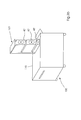
- the structure of a processing module 40 is shown schematically in FIG. 4.
- the Processing module 40 is according to the invention with a two-part rotary Machining tool 45 equipped.
- a tool roller 41 and a die roller 41 ' which perform synchronized movements, e.g. by a Coupling by means of a gear or a toothed or V-belt or other Coupling mechanisms known to those skilled in the art.
- the top Machining tool 41 carries tool elements 42, 71, 71, 82, 83, 86, 87, 91, 92, 96, 97, depending on the processing mode of the processing module 40.
- This Tool elements 42, 71, 71, 82, 83, 86, 87, 91, 92, 96, 97 protrude beyond the circumference of the Tool roller out and thereby dive when the upper movement rotates Processing tool in the plane in which the sheet-shaped substrates 1 move, one, whereby the processing of the sheet-shaped substrates is achieved.
- the lower processing tool has matrices 42 'which correspond to the respective Tool elements 42, 71, 71, 82, 83, 86, 87, 91, 92, 96, 97 of the upper one Machining tool 41 correspond and with these tool elements 42, 71, 71, 82, 83, 86, 87, 91, 92, 96, 97 for processing a continuous sheet Printing material are engaged during the rotation of the rollers 41, 41 '. Thereby, that the die roller 41 ', which is in constant operative connection with the tool roller 41 stands with the tool roller 41 together when exchanging processing modules 40, 40 'is replaced, there is no time-consuming adjustment between the two rollers 41, 41 ', which would otherwise have to take place with each change.
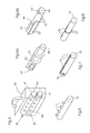
- FIGS. 5 to 8 Examples of different tool rolls 41, 70, 80, 85, 90, 95 for different ones Processing modules 40, 41 are shown in FIGS. 5 to 8.
- processing module 40 for punching holes in sheet-like Substrates 1 e.g. for filing in folders or for preparation for a subsequent one Wire comb binding is the upper processing tool 41 Stamping tool 70.
- Radial are located on the circumference of stamping tool 70 Punching elements 71.
- a change between different punching patterns is here by radial sinking of the stamp under the circumference of the punch 70 possible.
- the tool roller 41 is a Cutting tool 80. Radial are located on the circumference of the cutting tool 80 transverse cutting elements 81 and / or longitudinal cutting elements 82 e.g. to Format reduction or edge trimming and / or cutting elements 83 for production of windows or other forms in a sheet-like printing material 1, as e.g. are often inserted into the covers of so-called softcover books.
- FIG. 6b shows a processing tool 85 for producing edge trimming for Register shown.
- one of the cutting edges 87 is essentially parallel to the side edge aligned into which the register is to be inserted.
- At least a second cutting edge 86 cuts across and leads to a complete separation of the superfluous Material.
- embossing sheet-shaped Printing material 1 is the tool roller 41 an embossing tool 90.
- embossing grooves 91 radially on the circumference of the embossing tool, which e.g. can run axially or in the circumferential direction and / or stamp for impressing Lettering 92 or emblems, logos or other.
- Printing materials 1 is that of the tool roller 41 Perforating tool 95.
- Perforating tool 95 are located radially on the circumference of the Perforating tool 95 axial perforating needles 96 or perforating needles in Circumferential direction 97 e.g. for the corresponding production of tear-off edges in a sheet-shaped printing material.
Landscapes
- Engineering & Computer Science (AREA)
- Mechanical Engineering (AREA)
- Life Sciences & Earth Sciences (AREA)
- Forests & Forestry (AREA)
- Perforating, Stamping-Out Or Severing By Means Other Than Cutting (AREA)
- Inking, Control Or Cleaning Of Printing Machines (AREA)
- Folding Of Thin Sheet-Like Materials, Special Discharging Devices, And Others (AREA)
Abstract
Description
- Bereitstellen einer erfindungsgemäßen Vorrichtung gemäß der vorangegangenen Beschreibung,
- Lösen der lösbaren Befestigung zwischen mindestens einem Aufnahmeplatz und dem darin lösbar befestigten Bearbeitungsmodul mit mindestens einem Bearbeitungsmodus,
- manuelles Herausnehmen des Bearbeitungsmoduls,
- manuelles Einsetzen eines anderen Bearbeitungsmoduls mit einem anderen Bearbeitungsmodus,
- Schließen der lösbaren Befestigung zwischen dem Aufnahmeplatz und dem anderen Bearbeitungsmodul.
- automatisches Konfigurieren der Vorrichtung bezüglich des neuen Bearbeitungsmoduls.
- Fig. 1
- eine schematische Draufsicht der erfindungsgemäßen Vorrichtung;
- Fig. 2
- eine schematische Seitenansicht der erfindungsgemäßen Vorrichtung;
- Fig. 3a
- eine schematische perspektivische Ansicht einer bevorzugten Ausrührungsform mit mehren Aufnahmeplätzen;
- Fig. 3b
- eine schematische perspektivische Ansicht einer bevorzugten Ausführungsform mit automatischem Wechsler für Bearbeitungsmodule
- Fig. 4
- eine schematische Ansicht eines Bearbeitungsmoduls der erfindungsgemäßen Vorrichtung;
- Fig. 5
- eine schematische Darstellung einer beispielhaften Ausführungsform einer Werkzeugwalze für ein Stanzmodul;
- Fig. 6a
- eine schematische Darstellung einer beispielhaften Ausführungsform einer Werkzeugwalze für ein Schneidemodul;
- Fig. 6b
- eine schematische Darstellung einer beispielhaften Ausführungsform einer Werkzeugwalze für ein Schneidemodul für das Kantenbeschneiden für Registerblätter;
- Fig. 7
- eine schematische Darstellung einer beispielhaften Ausführungsform einer Werkzeugwalze für ein Prägemodul;
- Fig. 8
- eine schematische Darstellung einer beispielhaften Ausführungsform einer Werkzeugwalze für ein Perforiermodul;
- 1
- blattförmiger Bedruckstoff
- 2
- Transportrollen
- 3
- Bewegungsrichtung der axial verschiebbaren Transportrollen
- 4
- Bewegungsrichtung eines blattförmigen Bedruckstoffs durch die Vorrichtung
- 5
- Bewegungsrichtung des Schräglaufs
- 6
- Bewegungsrichtung der Kurvenscheibe
- 7
- Bewegungsrichtung des Anschlags
- 8
- Bewegungsrichtung der Gegenrollen
- 9, 9'
- Bewegungsrichtung des Bearbeitungswerkzeugs
- 10
- Preregistratur
- 11
- axial verschiebbare Transportrollen
- 12
- Motor
- 14
- Transportrollen
- 20
- Registratur
- 21
- Kugelleiste
- 22
- Kugel
- 23
- Anschlag
- 24
- Riemenzug
- 25
- Kurvenscheibe
- 26
- Gegenrollen
- 27
- Transportrollen
- 28
- schräglaufendes Transportband
- 30
- Kantensensor
- 40, 40'
- Bearbeitungsmodul
- 41,
- Werkzeugwalze
- 41'
- Matrizenwalze
- 42
- Werkzeugselement
- 42'
- Matrize
- 43
- Transportrollen
- 44
- Schnittstelle
- 45
- Bearbeitungswerkzeug
- 50
- Aufnahmeplatz
- 51
- Aufnahmeplatz
- 52
- Aufnahmeplatz
- 53
- Aufnahmeplatz
- 60
- Auffangbehälter für Abfall
- 70
- Stanzwerkzeug
- 71
- Stanzelement (Stempel)
- 80
- Schneidewerkzeug
- 81
- Querschneidelement
- 82
- Längsschneideelement
- 83
- Fensterschneideelement
- 85
- Registerschneidewerkzeug
- 86
- Registerschneide
- 87
- Registerschneide
- 90
- Prägewerkzeug
- 91
- Prägerillen
- 92
- Textprägestempel
- 95
- Perforierwerkzeug
- 96
- Querperforationsnadeln
- 97
- Längsperforationsnadeln
- 100
- erfindungsgemäße Vorrichtung
- 110
- Gehäuse der Vorrichtung
- 111
- Zusatzgehäuse
- 112
- Zusatzgehäuse
- 113
- Zusatzgehäuse
- 120
- Bearbeitungsmodulwechsler
- A
- Abstand Seitenkante/Mittellinie
- M
- Mittellinie des Transportpfades blattförmiger Bedruckstoffe
Claims (24)
dadurch gekennzeichnet, dass das zweiteilige Bearbeitungswerkzeug (45) in einem Bearbeitungsmodul (40, 40') angeordnet ist und die Vorrichtung (100) einen Aufnahmeplatz (50) umfasst, an dem das Bearbeitungsmodul (40, 40') austauschbar befestigt ist, wobei der Aufnahmeplatz (50) auch mindestens ein Bearbeitungsmodul (40, 40') mit mindestens einem anderen Bearbeitungsmodus aufnehmen kann.
dadurch gekennzeichnet, dass es sich bei dem Bearbeitungsmodus des Bearbeitungswerkzeugs (45) um mindestens einen der Bearbeitungsmodi Stanzen, Schneiden, Prägen, Rillen, Falten oder Perforieren handelt.
dadurch gekennzeichnet, dass die Vorrichtung (100) mindestens eine Registrierungsvorrichtung (10, 20) zur Ausrichtung der blattförmigen Bedruckstoffe (1) während des Einlaufens in die Vorrichtung (100) stromabwärts vor dem Bearbeitungsmodul (40, 40') aufweist.
dadurch gekennzeichnet, dass die Registrierungsvorrichtung (20) ein auf einem Durchlaufspfad transportierten blattförmigen Bedruckstoff (1) mittels eines Schräglaufs (21, 22, 28) mittig zum Durchlaufspfad ausrichtet, insbesondere entsprechend des Formats des blattförmigen Bedruckstoffs (1).
dadurch gekennzeichnet, dass das zum Durchlaufspfad mittige Ausrichten des blattförmigen Bedruckstoffs (1) durch einen automatisch verschiebbaren Anschlag (23) durchgeführt wird.
dadurch gekennzeichnet, dass die Vorrichtung stromaufwärts von dem Bearbeitungsmodul (40, 40') mindestens eine Sensorvorrichtung (30) zur Steuerung des Bearbeitungsvorgangs aufweist.
dadurch gekennzeichnet, dass die Sensorvorrichtung (30) die Vorderkante eines durchlaufenden blattförmigen Bedruckstoff (1) detektiert und dadurch der Bearbeitungsvorgang ausgelöst wird.
dadurch gekennzeichnet, dass das Detektieren wahlweise unmittelbar oder verzögert zur Auslösung des Bearbeitungsvorgangs führt.
dadurch gekennzeichnet, dass in einem Bypass- Betrieb bei mindestens einem Bearbeitungsmodul (40, 40') kein Bearbeitungsvorgang ausgelöst wird, sondern ein einlaufender blattförmiger Bedruckstoff (1) an dem betreffenden Bearbeitungsmodul (40, 40') vorbei transportiert wird.
dadurch gekennzeichnet, dass bei dem zweiteiligen Bearbeitungswerkzeug (45) eine Werkzeugwalze (41) oberhalb des Durchlaufspfad eines blattförmigen Bedruckstoffes (1) angeordnet ist, wobei die Werkzeugwalze (41) mindestens ein Werkzeugelement (42) trägt, das über den Umfang des ersten Werkzeugwalze (41) hinausragt und eine Matrizenwalze (41') unterhalb des Durchlaufspfads angeordnet ist, wobei die Matrizenwalze (41') mindestens allen Werkzeugelementen (42) der Werkzeugwalze (41) entsprechende Matrizen (42') aufweist und die beiden Walzen (41, 41') derart in einem Bearbeitungsmodul (40, 40') angeordnet sind und in Wirkverbindung miteinander stehen, so dass bei gegenläufigem Drehen der Walzen (41, 41') um ihre Achsen die Werkzeugelemente (42) der Werkzeugwalze (41) in Eingriff mit den korrespondierenden Matrizen (42') des Matrizenwalze (41') geraten.
dadurch gekennzeichnet, dass es sich bei einem Bearbeitungsmodul (40, 40') um ein Stanzmodul handelt, wobei die Werkzeugelemente (42) Stempel (71) darstellen, die in mindestens einer möglichen Lochkombination auf der Werkzeugwalze (41, 70) angeordnet sind, zum Einbringen von Löchern in einen durchlaufenden blattförmigen Bedruckstoff (1).
dadurch gekennzeichnet, dass das Stanzmodul zwischen unterschiedlichen Lochkombinationen wechseln kann, in dem die Lage von einigen der sich auf dem Umfang der Werkzeugwalze (41, 70) befindlichen Stempel (71) radial ändern lässt, insbesondere sich diese Stempel (71) versenken lassen und so nicht zur Herstellung von Löchern im blattförmigen Bedruckstoff (1) beitragen.
dadurch gekennzeichnet, dass Stanzabfall durch das Innere der Matrizenwalze (41') nach außen transportiert wird.
dadurch gekennzeichnet, dass es sich bei mindestens einem Bearbeitungsmodul (40, 40') um ein Schneidemodul handelt, bei dem die Werkzeugelemente (42) auf dem Umfang der Werkzeugwalze (41, 80) angebrachten Schneiden (81, 82, 83, 86, 87) darstellen, zum Beschneiden von blattförmigen Bedruckstoffen (1).
dadurch gekennzeichnet, dass es sich bei dem Schneidemodul um eine Vorrichtung für den Kantenbeschnitt für Registerblätter handelt, wo bei die Werkzeugelemente (42) auf dem Umfang der Werkzeugwalze (41, 85) Schneiden (86, 87) darstellen, die derart geformt sind, so dass aus einer Kante eines blattförmigen Bedruckstoffs (1) ein Registereingriff ausgeschnitten wird.
dadurch gekennzeichnet, dass mittels des Schneidemoduls insbesondere eine Formatsverkleinerung der blattförmigen Bedruckstoffe (1) durchgeführt werden kann, insbesondere eine Verkleinerung von A3 auf A4 und/oder A4 auf A5.
dadurch gekennzeichnet, dass es sich bei mindestens einem Bearbeitungsmodul (40, 40') um ein Prägemodul handelt, bei dem mittels auf dem Umfang der Werkzeugwalze (41, 90) angebrachten Stempeln (91, 92) blattförmige Bedruckstoffe (1) geprägt werden, insbesondere mit einem Schriftzug versehen werden.
dadurch gekennzeichnet, dass bei dem Prägemodul die Werkzeugelemente (42, 91, 92) achsparallel und/oder in Umfangsrichtung auf dem Umfang der Werkzeugwalze (42, 90) angebrachte stumpfe Klingen (91) darstellen, mittels deren blattförmige Bedruckstoffe (1) gerillt werden, insbesondere um ein anschließendes Falten der blattförmige Bedruckstoffe (1) zu unterstützen.
dadurch gekennzeichnet, dass es sich bei mindestens einem Bearbeitungsmodul (40, 40') um ein Perforiermodul handelt, bei dem die Werkzeugelemente (42, 96, 97) auf dem Umfang der Werkzeugwalze (41, 95) angebrachten Nadeln (96, 97) darstellen, zur Perforation von blattförmigen Bedruckstoffen (1).
dadurch gekennzeichnet, dass die Vorrichtung (100) mindestens zwei Bearbeitungsmodule (40, 40') aufweist und es sich bei den Bearbeitungsmodulen (40, 40') um eine beliebige Kombination aus Stanzmodulen, Schneidemodulen, Prägemodulen und/oder Perforiermodulen handelt.
dadurch gekennzeichnet dass der Wechsel von Bearbeitungsmodulen (40, 40') mittels eines Bearbeitungsmodulwechslers (120) automatisch erfolgt.
Applications Claiming Priority (2)
| Application Number | Priority Date | Filing Date | Title |
|---|---|---|---|
| DE10137165 | 2001-07-30 | ||
| DE2001137165 DE10137165A1 (de) | 2001-07-30 | 2001-07-30 | Vorrichtung zum fliegenden mechanischen Bearbeiten von blattförmigen Bedruckstoffen |
Publications (2)
| Publication Number | Publication Date |
|---|---|
| EP1281488A2 true EP1281488A2 (de) | 2003-02-05 |
| EP1281488A3 EP1281488A3 (de) | 2005-03-09 |
Family
ID=7693644
Family Applications (1)
| Application Number | Title | Priority Date | Filing Date |
|---|---|---|---|
| EP02015028A Withdrawn EP1281488A3 (de) | 2001-07-30 | 2002-07-05 | Vorrichtung sowie Verfahren zum fliegenden mechanischen Bearbeiten von blattförmigen Bedruckstoffen durch Bearbeitungsmodule |
Country Status (5)
| Country | Link |
|---|---|
| EP (1) | EP1281488A3 (de) |
| JP (1) | JP2003175492A (de) |
| CN (1) | CN1400097A (de) |
| DE (1) | DE10137165A1 (de) |
| RU (1) | RU2002120069A (de) |
Cited By (4)
| Publication number | Priority date | Publication date | Assignee | Title |
|---|---|---|---|---|
| WO2005110687A1 (en) * | 2004-05-11 | 2005-11-24 | Ellison Educational Equipment, Inc. | Die press with removable cartridge roller |
| WO2009049898A3 (de) * | 2007-10-17 | 2010-07-01 | Hans Lingl Anlagenbau Und Verfahrenstechnik Gmbh & Co. Kg | Vorrichtung zum trennen eines längs eines förderdurchgangs bewegbaren plastischen stranges, mit wenigstens einem kerbleisten und schneidedrahthalter tragenden trägermodul |
| CN103203898A (zh) * | 2013-04-25 | 2013-07-17 | 杭州惠宝机电有限公司 | 快换式纸张双向压痕部件和双向压痕装置 |
| WO2013164141A1 (de) * | 2012-05-02 | 2013-11-07 | Bielomatik Leuze Gmbh + Co. Kg | Vorrichtung zum bearbeiten von blatt- oder bogenförmigen gütern |
Families Citing this family (13)
| Publication number | Priority date | Publication date | Assignee | Title |
|---|---|---|---|---|
| DE10309952A1 (de) * | 2003-03-07 | 2004-09-16 | Heidelberger Druckmaschinen Ag | Verfahren zur Unterstützung des Einrichtens einer Stanzvorrichtung mit veränderbarem Lochmuster |
| DE10309953A1 (de) * | 2003-03-07 | 2004-09-16 | Heidelberger Druckmaschinen Ag | Werkzeugwalze zur Erzeugung von unterschiedlichen Lochbildern in blattförmigen Bedruckstoffen |
| EP1719726B1 (de) | 2004-02-24 | 2013-09-25 | Duplo Seiko Corporation | Papierbogenverarbeitungsvorrichtung |
| DE102004011898A1 (de) * | 2004-03-11 | 2005-09-29 | Heidelberger Druckmaschinen Ag | Vorrichtung zum rotativen Bearbeiten von blattförmigen Materialien |
| DE102005011568A1 (de) * | 2004-04-13 | 2005-11-17 | Man Roland Druckmaschinen Ag | Produktionsverfahren für eine Prägeeinrichtung in einer Bogendruckmaschine |
| JP4975392B2 (ja) * | 2006-08-01 | 2012-07-11 | 株式会社塚谷刃物製作所 | フレキシブルダイ |
| JP4850613B2 (ja) * | 2006-08-03 | 2012-01-11 | 株式会社リコー | 用紙処理装置及び画像形成システム |
| CN102184762B (zh) * | 2011-03-01 | 2014-04-16 | 深圳市得润电子股份有限公司 | 一种软性排线冲模装置及方法 |
| JP6216186B2 (ja) * | 2013-08-30 | 2017-10-18 | デュプロ精工株式会社 | 用紙加工装置 |
| CN104339829B (zh) * | 2014-11-19 | 2016-07-13 | 昆山市周庄镇黎明印刷厂 | 印刷折边机 |
| DE102019110853B4 (de) * | 2019-04-26 | 2022-05-12 | Koenig & Bauer Ag | Bogenbearbeitungsmaschine und Verfahren zur Inspektion zumindest eines verbliebenen und von einer Formgebungseinrichtung bearbeiteten Teils zumindest eines Bogens |
| CN112677239B (zh) * | 2020-12-21 | 2025-07-18 | 佛山市金页盈信智能机械有限公司 | 一种冲切书页的生产线 |
| CN113635399A (zh) * | 2021-08-09 | 2021-11-12 | 丰城市星泽科技有限公司 | 一种卷筒料瓦楞模切机 |
Family Cites Families (20)
| Publication number | Priority date | Publication date | Assignee | Title |
|---|---|---|---|---|
| US3194095A (en) * | 1962-12-31 | 1965-07-13 | Lloyd P Buck | Punch confett remover |
| US3844201A (en) * | 1971-06-02 | 1974-10-29 | Fmc Corp | Apparatus for cutting sheet material |
| DE2254281A1 (de) * | 1972-11-06 | 1974-05-22 | Hillesheimer Walter Dipl Ing D | Vorrichtung zum stanzen von formlingen oder materialbahnen |
| FR2360391A1 (fr) * | 1976-08-05 | 1978-03-03 | Chambon Machines | Machine de decoupage d'une nappe de materiau |
| US4594926A (en) * | 1983-10-24 | 1986-06-17 | Didde Graphic Systems Corporation | File hole punch ring apparatus for web fed paper conveying mechanism |
| DE3419254C1 (de) * | 1984-05-23 | 1985-10-10 | Lutz H. 8000 München Prüfer | Kopiergeraet mit Kopielocheinrichtung |
| DE3439199C1 (de) * | 1984-10-26 | 1986-02-20 | Maschinenbau Werner Bonnet, 7140 Ludwigsburg | Perforiergerät |
| US4819021A (en) * | 1987-12-10 | 1989-04-04 | Xerox Corporation | Copier on-line variable tab cutter |
| SE8803351D0 (sv) * | 1988-09-21 | 1988-09-21 | Akv I Kopparberg Ab | Anordning for riggning av skerverk och liknande |
| US5098366A (en) * | 1989-06-16 | 1992-03-24 | Gressman Richard H | Rotary cutters for business folders with multiple tab options |
| US5088367A (en) * | 1990-07-30 | 1992-02-18 | Zerand-Bernal Group, Inc. | Rotary die with adjustable blade segment |
| US5131901A (en) * | 1991-07-01 | 1992-07-21 | Moll Richard J | Scoring and perforating apparatus |
| DE4123807C1 (de) * | 1991-07-18 | 1992-06-04 | Sundwiger Eisenhuette Maschinenfabrik Gmbh & Co, 5870 Hemer, De | |
| US5669277A (en) * | 1993-01-29 | 1997-09-23 | Perrone; Sal | Method of die-punching holes in paper |
| WO1998055278A1 (de) * | 1997-06-06 | 1998-12-10 | Koenig & Bauer Aktiengesellschaft | Verfahren sowie einrichtung zum querperforieren einer laufenden papierbahn |
| DK0918592T3 (da) * | 1997-06-21 | 2003-06-16 | Feintool Int Holding | Produktions- og/eller montageapparat |
| DE29818847U1 (de) * | 1998-10-22 | 1999-01-28 | Maschinenfabrik Goebel Gmbh, 64293 Darmstadt | Einrichtung zum Verarbeiten eines Substrates |
| DE19907357A1 (de) * | 1999-02-20 | 2000-08-24 | Bielomatik Leuze & Co | Querbearbeiter für Lagenmaterial, insbesondere Querschneider für Papier |
| DE19919345C1 (de) * | 1999-04-28 | 2000-09-28 | Schober Werkzeug & Maschbau | Vorrichtung zum Herstellen eines Ordnerregisters |
| DE19944581C1 (de) * | 1999-09-17 | 2000-12-14 | Woschnik & Partner Maschb Gmbh | Flachbett-Bogenstanze, insbesondere zur Herstellung von Papier- oder Kartonzuschnitten |
-
2001
- 2001-07-30 DE DE2001137165 patent/DE10137165A1/de not_active Withdrawn
-
2002
- 2002-07-05 EP EP02015028A patent/EP1281488A3/de not_active Withdrawn
- 2002-07-22 CN CN 02126531 patent/CN1400097A/zh active Pending
- 2002-07-29 RU RU2002120069/12A patent/RU2002120069A/ru not_active Application Discontinuation
- 2002-07-29 JP JP2002219528A patent/JP2003175492A/ja active Pending
Cited By (5)
| Publication number | Priority date | Publication date | Assignee | Title |
|---|---|---|---|---|
| WO2005110687A1 (en) * | 2004-05-11 | 2005-11-24 | Ellison Educational Equipment, Inc. | Die press with removable cartridge roller |
| WO2009049898A3 (de) * | 2007-10-17 | 2010-07-01 | Hans Lingl Anlagenbau Und Verfahrenstechnik Gmbh & Co. Kg | Vorrichtung zum trennen eines längs eines förderdurchgangs bewegbaren plastischen stranges, mit wenigstens einem kerbleisten und schneidedrahthalter tragenden trägermodul |
| WO2013164141A1 (de) * | 2012-05-02 | 2013-11-07 | Bielomatik Leuze Gmbh + Co. Kg | Vorrichtung zum bearbeiten von blatt- oder bogenförmigen gütern |
| CN103203898A (zh) * | 2013-04-25 | 2013-07-17 | 杭州惠宝机电有限公司 | 快换式纸张双向压痕部件和双向压痕装置 |
| CN103203898B (zh) * | 2013-04-25 | 2017-10-03 | 杭州惠宝机电有限公司 | 快换式纸张双向压痕部件和双向压痕装置 |
Also Published As
| Publication number | Publication date |
|---|---|
| EP1281488A3 (de) | 2005-03-09 |
| DE10137165A1 (de) | 2003-02-27 |
| CN1400097A (zh) | 2003-03-05 |
| JP2003175492A (ja) | 2003-06-24 |
| RU2002120069A (ru) | 2004-04-10 |
Similar Documents
| Publication | Publication Date | Title |
|---|---|---|
| DE3751151T2 (de) | Bearbeitung von Papier- und anderen Bahnen. | |
| DE10137165A1 (de) | Vorrichtung zum fliegenden mechanischen Bearbeiten von blattförmigen Bedruckstoffen | |
| EP2308681B1 (de) | Formatvariable einrichtung zum schneiden von bedruckstoffen sowie falzapparat und druckmaschine mit solcher einrichtung | |
| DE2921337C2 (de) | Verfahren zum Steuern des Betriebsablaufs in einer automatischen Postabfertigungsvorrichtung sowie Vorrichtung zur Ausführung des Verfahrens | |
| DE2745854B2 (de) | Wellpappenanlage zum Herstellen bedruckter Wellpappenzuschnitte | |
| US20030036468A1 (en) | Device and method for automatic processing of sheet-shaped print materials with interchangeable functions | |
| EP2502862B1 (de) | Verfahren und Vorrichtung zum Verarbeiten von Bogen unterschiedlichen Formats | |
| EP1837137A1 (de) | Querschneidevorrichtung und Verfahren zum Betrieb einer solchen Querschneidevorrichtung | |
| DE4443031A1 (de) | Transportsystem für ein Wellpappenblatt in einer Drucklinie | |
| DE1284394B (de) | Vorrichtung zum Zusammenfuehren und Verbinden mehrerer durchlaufender Bahnen aus biegsamem Papiermaterial zwecks Ausbildung von Kopiersaetzen | |
| EP1922276B1 (de) | Falzapparat | |
| EP0019202A1 (de) | Falzvorrichtung zu einer Rotationsdruckmaschine | |
| CH615134A5 (en) | Folding apparatus for rotary printing machines having a magazine-cutting facility | |
| DE19927920A1 (de) | Schneideinrichtung im Falzapparat einer Rotationsdruckmaschine und Falzapparat mit einer solchen Schneideinrichtung | |
| EP1140517A1 (de) | Sammelheftmaschine und verfahren zum herstellen eines aufschlagregisters an mittels einer sammelheftmaschine zu heftenden druck- oder papierwerken | |
| DE102014205939A1 (de) | Verfahren und Vorrichtung zur Herstellung eines Druckproduktes sowie Druckprodukt | |
| DE10248688B4 (de) | Vorrichtung zur Erzeugung von unterschiedlichen Lochbildern in blattförmigen Bedruckstoffen | |
| DE102006016266B3 (de) | Vorrichtung zur Bearbeitung einer laufenden Materialbahn | |
| EP1603716B1 (de) | Werkzeugwalze zur erzeugung von unterschiedlichen lochbildern in blattförmigen bedruckstoffen | |
| EP1839858A2 (de) | Falzapparat einer Druckmaschine und Verfahren zum Betreiben desselben | |
| EP1156006A2 (de) | Trommelfalzapparat mit einem Falzmesserzylinder | |
| EP3558689B1 (de) | Verfahren und vorrichtung zum herstellen von druckschriften | |
| DE102004005807B4 (de) | Falzapparat | |
| DE2365668C3 (de) | Vorrichtung zur Verarbeitung bahnförmigen Materials mit einem Rotationsdruckwerk | |
| EP1603717B1 (de) | Verfahren zur unterstützung des einrichtens einer stanzvorrichtung mit veränderbarem lochmuster |
Legal Events
| Date | Code | Title | Description |
|---|---|---|---|
| PUAI | Public reference made under article 153(3) epc to a published international application that has entered the european phase |
Free format text: ORIGINAL CODE: 0009012 |
|
| AK | Designated contracting states |
Designated state(s): AT BE BG CH CY CZ DE DK EE ES FI FR GB GR IE IT LI LU MC NL PT SE SK TR |
|
| AX | Request for extension of the european patent |
Extension state: AL LT LV MK RO SI |
|
| PUAL | Search report despatched |
Free format text: ORIGINAL CODE: 0009013 |
|
| AK | Designated contracting states |
Kind code of ref document: A3 Designated state(s): AT BE BG CH CY CZ DE DK EE ES FI FR GB GR IE IT LI LU MC NL PT SE SK TR |
|
| AX | Request for extension of the european patent |
Extension state: AL LT LV MK RO SI |
|
| AKX | Designation fees paid | ||
| REG | Reference to a national code |
Ref country code: DE Ref legal event code: 8566 |
|
| STAA | Information on the status of an ep patent application or granted ep patent |
Free format text: STATUS: THE APPLICATION IS DEEMED TO BE WITHDRAWN |
|
| 18D | Application deemed to be withdrawn |
Effective date: 20050910 |