EP1280679B1 - Beleuchtungsvorrichtung - Google Patents
Beleuchtungsvorrichtung Download PDFInfo
- Publication number
- EP1280679B1 EP1280679B1 EP01940195A EP01940195A EP1280679B1 EP 1280679 B1 EP1280679 B1 EP 1280679B1 EP 01940195 A EP01940195 A EP 01940195A EP 01940195 A EP01940195 A EP 01940195A EP 1280679 B1 EP1280679 B1 EP 1280679B1
- Authority
- EP
- European Patent Office
- Prior art keywords
- light
- lens
- light source
- illumination device
- scale
- Prior art date
- Legal status (The legal status is an assumption and is not a legal conclusion. Google has not performed a legal analysis and makes no representation as to the accuracy of the status listed.)
- Expired - Lifetime
Links
- 238000005286 illumination Methods 0.000 title claims description 24
- 230000003287 optical effect Effects 0.000 claims description 15
- 239000000463 material Substances 0.000 claims description 11
- 239000004973 liquid crystal related substance Substances 0.000 claims description 9
- 229920003023 plastic Polymers 0.000 claims description 9
- 238000001746 injection moulding Methods 0.000 claims 1
- 210000002858 crystal cell Anatomy 0.000 description 7
- 239000004033 plastic Substances 0.000 description 6
- 238000009826 distribution Methods 0.000 description 4
- 238000000149 argon plasma sintering Methods 0.000 description 3
- 239000002245 particle Substances 0.000 description 3
- 230000008901 benefit Effects 0.000 description 2
- 238000003384 imaging method Methods 0.000 description 2
- 238000004519 manufacturing process Methods 0.000 description 2
- 239000002184 metal Substances 0.000 description 2
- 239000004417 polycarbonate Substances 0.000 description 2
- 229920000515 polycarbonate Polymers 0.000 description 2
- 239000011248 coating agent Substances 0.000 description 1
- 238000000576 coating method Methods 0.000 description 1
- 239000004020 conductor Substances 0.000 description 1
- 230000008878 coupling Effects 0.000 description 1
- 238000010168 coupling process Methods 0.000 description 1
- 238000005859 coupling reaction Methods 0.000 description 1
- 230000001419 dependent effect Effects 0.000 description 1
- 238000004049 embossing Methods 0.000 description 1
- 230000002349 favourable effect Effects 0.000 description 1
- 238000000265 homogenisation Methods 0.000 description 1
- 238000000465 moulding Methods 0.000 description 1
- 239000013307 optical fiber Substances 0.000 description 1
- 239000004065 semiconductor Substances 0.000 description 1
- 230000009466 transformation Effects 0.000 description 1
- 230000007704 transition Effects 0.000 description 1
Images


Classifications
-
- B—PERFORMING OPERATIONS; TRANSPORTING
- B60—VEHICLES IN GENERAL
- B60Q—ARRANGEMENT OF SIGNALLING OR LIGHTING DEVICES, THE MOUNTING OR SUPPORTING THEREOF OR CIRCUITS THEREFOR, FOR VEHICLES IN GENERAL
- B60Q3/00—Arrangement of lighting devices for vehicle interiors; Lighting devices specially adapted for vehicle interiors
- B60Q3/10—Arrangement of lighting devices for vehicle interiors; Lighting devices specially adapted for vehicle interiors for dashboards
- B60Q3/14—Arrangement of lighting devices for vehicle interiors; Lighting devices specially adapted for vehicle interiors for dashboards lighting through the surface to be illuminated
-
- B—PERFORMING OPERATIONS; TRANSPORTING
- B60—VEHICLES IN GENERAL
- B60Q—ARRANGEMENT OF SIGNALLING OR LIGHTING DEVICES, THE MOUNTING OR SUPPORTING THEREOF OR CIRCUITS THEREFOR, FOR VEHICLES IN GENERAL
- B60Q3/00—Arrangement of lighting devices for vehicle interiors; Lighting devices specially adapted for vehicle interiors
- B60Q3/60—Arrangement of lighting devices for vehicle interiors; Lighting devices specially adapted for vehicle interiors characterised by optical aspects
- B60Q3/62—Arrangement of lighting devices for vehicle interiors; Lighting devices specially adapted for vehicle interiors characterised by optical aspects using light guides
- B60Q3/64—Arrangement of lighting devices for vehicle interiors; Lighting devices specially adapted for vehicle interiors characterised by optical aspects using light guides for a single lighting device
Definitions
- the invention relates to a lighting device according to the preamble of the main claim.
- Lighting devices are already known in which light sources for a backlighting of the display surface are arranged on a side facing away from the user. In order to allow a homogeneous brightness distribution when backlighting the display surface, the light emitted by the light sources must be strongly scattered, so that it can be distributed uniformly over the entire display surface. It is also known to arrange a light guide plate behind the display surface, on whose side surfaces light sources are arranged. The light of these light sources is coupled into the light guide plate and deflected in the direction of the display surface. This can be dispensed with a light scattering. However, provision must be made for the light deflection and space must be provided for the light source in a lateral area of the display.
- a lighting device in which the light from a light source via a reflector in an optical fiber, which rests on the reflector, is coupled. The coupling takes place by means of a recess introduced into the light guide. The light is now guided approximately perpendicular to the original light propagation direction in the light guide.
- EP 1055916 A2 lighting for a pointer instrument in which the light of a light source coupled into a light well and is forwarded therefrom by means of a lens, coupled and coupled in a pointer. In the pointer, the light is passed through a light guide.
- the lighting device according to the invention with the features of the main claim has the advantage that the light is homogeneously distributed through the use of a reflector and a lens between the light source and the display area on the entire display surface, so that a homogeneous illumination of the display area without additional, auflichde slides and can be done without an additional light scattering. It is particularly advantageous that a particularly efficient illumination of the display surface is made possible by the combined use of a reflector and a lens between the light source and the display surface, as well as laterally scattered light is reflected in the direction of the display surface.
- the measures listed in the dependent claims advantageous refinements and improvements of the main claim lighting device are possible. It is particularly advantageous to choose the distance of the lens to the light source in the region of the focal length of the lens. As a result, the lens does not function as an imaging optical system, but homogenizes the light distribution of the light source.
- the light shaft is advantageous to form as a parabolic reflector in order to obtain a particularly homogeneous light distribution.
- LEDs are inexpensive and easy to assemble.
- conventional light emitting diodes generally emit light in a preferred direction
- a Abstrahlungslichtkegel the LED expanded to illuminate a display area.
- the lens is advantageous to arrange the lens on a side of the light shaft facing away from the light source, as this causes the lens, e.g. is formed on a light guide, which is placed on the light shaft during manufacture of the lighting device. It is particularly advantageous to create a required plurality of lenses in one operation by molding on a light guide for each adjacent light sources.
- a lens on the light source, since in this case the light source and the lens can be created in a manufacturing process, wherein it is particularly advantageous to mold the lens to a body of the light emitting diode or e.g. to be formed by means of an embossing stamp.
- the lens in a region around the optical axis of the lens as a diverging lens and out of the region as a converging lens.
- the light distribution is homogenized by scattering the light in central, very bright areas of the light source and in edge areas in which the light source is dark, collected and directed in the direction of the display surface.
- the lighting device according to the invention for a backlighting of a flat display, as by the lighting device according to the invention a homogeneous backlighting even with favorable light sources, eg with light emitting diodes, is possible.
- a lighting device according to the invention for a scale display, in which individual scale segments can be illuminated separately and the associated lighting can each be controlled separately.
- a lighting device according to the invention for each scale segment on the one hand, homogeneous and efficient and, on the other hand, low-cost backlighting, e.g. be realized with respect to a regulation of a scale segment illumination by means of a liquid crystal cell.
- use for a cruise control display is advantageous in which individual segments are regularly activated or deactivated.
- FIG. 1a shows a first embodiment of a lighting device according to the invention in a side view and Figure 1b shows the first embodiment in a plan view.
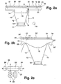
- FIG. 2 a shows a further embodiment according to the invention of a lighting device for a scale display in a first side view
- FIG. 2 b shows the second embodiment according to the invention in a further side view
- FIG. 2 c shows the second embodiment according to the invention in a plan view.
- FIG. 3 shows an exemplary embodiment of a light source according to the invention in a cross section.
- Figure 4a shows an embodiment of an arrangement of a lighting device according to the invention for backlighting a flat display.
- FIG. 4b shows a scale instrument illuminated by a lighting device according to the invention.
- FIG. 1 a shows a side view of a first exemplary embodiment of a lighting device according to the invention with a light source 1, which is arranged on a printed circuit board 2.
- a lens 3 is arranged, is directed by the light in a light shaft 4.
- the light shaft 4 is bounded laterally by a reflector 5.
- a lens 6 is arranged at a light source 1 opposite end of the light shaft 4.
- a liquid crystal cell 7 is arranged.
- the light source 1 is designed as a light emitting diode.
- the light source 1 is supplied via an unillustrated in the figure 1a printed conductors with an operating voltage.
- the deflected by the lens 3 light of the light source 1 strikes either directly on the lens 6 or on the reflector 5, which forms the walls of the light shaft 4.
- the reflector 5 is designed as a rotation body with a parabolic cross-section.
- the reflector 5 is preferably made of a white, light-reflecting plastic material.
- an embodiment as a metal reflector is possible.
- the diffuser 6 is made of a plastic material and, in a preferred embodiment, consists of a plastic material into which light-diffusing particles are introduced, for example particles of another plastic material having a different refractive index.
- a liquid crystal cell 7 is shown on the diffusing screen 6 in FIG. 1a, which in a preferred exemplary embodiment has pixels which can be controlled individually by electrical means.
- liquid crystal cell 7 Details of the liquid crystal cell 7 are not shown in FIG. 1a.
- the guided by the light source 1 via the lens 3 light only hits either directly on the Lens 6 or first on the reflector 5, from which it is passed to the lens 6.
- the diffuser 6 contributes to a further homogenization of the light and directs the light to the liquid crystal cell 7.
- a fixed display such as a dial or a warning field, eg from a be placed transparent plastic material with a printed warning symbol.
- a warning symbol may be printed directly on the lens 6.
- 1b is a plan view of the lighting device according to the invention, which has been described for the figure 1a, without the lens 6 and the liquid crystal cell 7 is shown.
- the light shaft 4 is formed by the reflector 5.
- the light source 1 is arranged with the lens 3.
- FIG. 2 a shows another exemplary embodiment of a lighting device according to the invention, in which a light source 10 is arranged on a printed circuit board 11.
- the light source 10 On the side facing away from the printed circuit board 11, the light source 10 is arranged on a light shaft 12 or at least partially projecting into the light shaft 12, which is formed by a reflector 13.
- the reflector 13 is formed from a carrier 14.
- a lens 15 On the side facing away from the light source 10 of the light shaft 12, a lens 15 is arranged, which is integrally formed on a light guide 16 which rests on the carrier 14.
- a side surface 17 of the light guide light from a light guide plate 18 can be coupled, which is arranged laterally adjacent to the light guide 16 and adjacent to the light guide 16.
- the light guide plate 18 can be illuminated by a further light source 19.
- the light source 10 is through the Light shaft 12 forming carrier 14 optically separated from the further light source 19.
- a dial 20 is arranged on the side facing away from the light source 10 of the light guide 16.
- the dial 20 has first portions 21, which are opaque, and second portions 22, which are translucent.
- the light source 10 is preferably designed as a light-emitting diode, which is supplied via the circuit board 11 with an operating voltage.
- the carrier 14 is executed in a preferred embodiment of colored with white color particles plastic material such as polycarbonate. As a result, the reflector 13 can be formed by a surface of the carrier 14. In an embodiment not shown in Figure 2a, a metal coating of the carrier 14 is possible.
- the light emitted by the light source 10 either passes directly to the lens 15 or is first deflected via the reflector 13 to the lens 15.
- the dial 20 is preferably made of a transparent plastic material, in which the opaque first regions 21 are applied, for example by printing. By an appropriate imprint symbols, scale segments or numbers can be formed.
- the further light source 19 light can be emitted to the light guide plate 18, wherein the light guide plate is preferably made of a light-scattering material. From the light guide plate 18, light is transmitted through translucent second regions 22 of the dial 20.
- light is deflected by the light guide plate 18 to the first side surface 17 of the light guide 16, so that even in the event that the light source 10 is not operated, a segment 22 'on the side facing away from the light source 10 of the lens 15 is at least weakly illuminated , The segment 22 'is then recognizable even when the light source 10 is switched off.
- a switchover between a weakly lit state namely a lighting on the further light source 19 ensures the light guide plate 18 and the light guide 16 and a brightly lit state when the light source 10 is turned on. From the light source 10, however, only slightly light is transmitted to the light guide plate 18, since the light is directed through the lens 15 in the direction of the segment 22 '.
- the light guide 16 and the light guide plate 18 are made in a preferred embodiment of polycarbonate, wherein the light guide 16 and the lens 15 in this case are preferably made transparent.
- FIG. 2b shows another side view of the lighting device according to the invention according to FIG. 2a.
- the light guide 16 On the support 14 is the light guide 16, on which the lens 15 is formed, with bearing surfaces 23, 23 'on.
- the lens 15 bulges convexly in the direction of the light source 10.
- the distance of the lens 15 to the light source 10 is approximately equal to the focal length of the lens 15.
- the lens 15 is not imaging but performs a Fourier transformation of the image in the focal plane such that the segment 22 By non-opaque first regions 21, the segment 22 'is separated from other, transparent regions, ie segments 24, 24' of the dial 20, so that a separate backlighting of the segments 22 ' , 24 ' and 24 is possible
- the reflector 13 has in the embodiment according to the figure 2a and 2b linearly extending walls a preferred embodiment, the limited by the reflector 13
- Light shaft 12 in a section parallel to the lens plane of the lens 15 has a rectangular cross-section.
- FIG. 2c shows a plan view of the dial 20, behind which the illumination device according to the invention described with reference to FIGS. 2a and 2b is arranged.
- a section through the illumination device according to the invention is shown in dashed lines in FIG. 2c, wherein the section according to FIG. 2a is identified by the letter a and the section according to FIG. 2b by the letter b.
- a number is represented by translucent second regions 22, which is formed from transparent regions of the dial 20.
- the number is backlit by the further light source 19 and the light guide plate 18.
- the segment 22 ' is illuminated by the light source 10 separately from the segments 24 and 24', which are individually controllable in a preferred embodiment in each case by a lighting device according to the invention. Due to the light guide plate 18, a basic brightness of the segments is ensured even when the light sources are switched off behind the segments 22 ', 24 and 24'.
- Figure 3 shows an embodiment of an inventive arrangement of the lens directly to the light source.
- the light source described with reference to FIG. 3 is used in particular as the light source 1 in the exemplary embodiment illustrated in FIG. 1a.
- a light-emitting diode instead of a light-emitting diode, an incandescent lamp, a glow lamp and / or a fluorescent lamp can also be used.
- the arrangement of a lens on a light source 1 embodied as a light-emitting diode, preferably as a so-called top light-emitting diode, will be explained with reference to FIG.
- the light source 1 has a light-generating region 30, preferably of a semiconductor material which is excited by emission lines, not shown in FIG. 3, for emission of light rays.
- the light source 1 further has a housing 31, on which the lens-generating region 30, the rotationally symmetrical to an optical axis 40 designed lens 3 is arranged.
- the lens 3 has a first region 33 and a second region 32, the first region 33 being arranged below a surface 34 of the housing 31 and the surface 34 pointing in the direction of the lens 6.
- the second region 32 is arranged on the side of the surface 34 facing the lens 6.
- the first region 33 comprises the light-generating region 30 and is designed cup-shaped.
- On a parallel to the surface 34 extending pot bottom 35 close linearly extending side surfaces 36 which extend up to the surface 34 of the housing 31.
- the side surfaces 36 are reflective in a preferred embodiment and, like the housing 31, are made of a white plastic material.
- a transition between the first region 33 and the second region 32 is represented by a dotted line 39, through which a diameter of the lens 3, ie a double lens radius, is given.
- the second region 32 is divided into an inner region 38 and an outer region 37 with respect to the optical axis 40, which extends perpendicular to the surface 34.
- a boundary of the inner region is given by a given radius about the optical axis 40, which is smaller than the lens radius.
- a surface of the lens 3 is concaved, so that the lens 3 in the inner region 38 is light-diffusing.
- a first light beam 41 from the light-generating region 30 is drawn, which traverses the inner region 38 and leaves the lens 3 in the inner region 38.
- the first light beam 41 is refracted away from the optical axis 40.
- the walls of the lens 3 Close in the outer region 37 on the one hand to the surface 34 of the housing 31 and on the other hand to the inner region 38 at.
- a surface of the lens 3 preferably extends linearly in the outer region 37 and forms a wall surrounding the inner region 38.
- a second light beam 42 starts at the light-generating area 30, leaves the lens in the outer area 37 and is thereby refracted towards the optical axis 40.
- FIG. 4 a shows a backlighting device 50 of a flat display, preferably a liquid crystal display, which is arranged in front of the backlighting device 50.
- a multiplicity of illumination sources with reflectors 51 and light sources 52 are arranged side by side in a planar manner and fill the surface of the backlighting device almost completely. In this way, a homogeneous backlighting of a display arranged in front of the backlighting device 50 is possible.
- FIG. 4b shows a scale display with a dial 60 on which a numerical value on a scale 64 is displayed by means of a pointer.
- the scale display is used for a speedometer in a motor vehicle.
- a pointer 61 is movable via a pointer shaft 63 and displays a value on a scale 64, which is labeled with numerical values 65.
- numerical values 65 "0", "20", “40", "60” and "80" are arranged on the scale 64.
- the scale 64 consists of individual scale segments 66, of which, for reasons of clarity of the drawing, only one scale segment 66 is provided with a reference numeral.
- the scale segments 66 are provided on the side facing away from the pointer 61 of the dial 60, each with a lighting device according to the invention, the each separately electrically controlled, so that the individual scale segments 66 are individually illuminated.
- the numerical values 65 can all be illuminated by a light source, by means of which light in accordance with the invention, as described with reference to FIG. 2a, is coupled into the scale segments 66 behind the scale segments 66 when the light sources 10 are switched off.
- the illumination devices are preferably controllable by a computing device, not shown in FIG. 4b, just as the pointer 61 can be controlled via a stepping motor arranged on the pointer shaft 63, which is likewise connected to the computing device.
- a numerical value of "60” is preselected by an input of a user, eg a speed of 60 km per hour, then all scale segments are illuminated by the illumination devices according to the invention starting from the numerical value 0 up to the numerical value "60".
- the scale segments of "60” to "100” remain in a dark state and are dimly lit only by the further light source 19, which also illuminates the numerical values 65.
- the speed 60 km per hour is a preferred embodiment, a preselected speed in a so-called cruise control in a motor vehicle, in which the computing unit is given a speed and in which a vehicle drive is controlled by the computing unit in such a way that the vehicle with the selected Speed drives.
- the actual vehicle speed is then displayed by the pointer 61 above the scale 64 so that a user can constantly compare between a desired speed, namely the speed represented over the brightly illuminated scale segments, eg 60 km / h, and the actual vehicle speed , Since the scale segments 66 are each individually controllable, other, any speed values can be preselected and be displayed by a corresponding illumination of the scale segments as a target speed.
Landscapes
- Engineering & Computer Science (AREA)
- Mechanical Engineering (AREA)
- Details Of Measuring Devices (AREA)
- Illuminated Signs And Luminous Advertising (AREA)
- Planar Illumination Modules (AREA)
- Instrument Panels (AREA)
- Non-Portable Lighting Devices Or Systems Thereof (AREA)
Description
- Die Erfindung geht aus von einer Beleuchtungsvorrichtung nach der Gattung des Hauptanspruchs. Es sind schon Beleuchtungsvorrichtungen bekannt, bei denen auf einer dem Benutzer abgewandten Seite Lichtquellen für eine Hinterleuchtung der Anzeigefläche angeordnet sind. Um eine homogene Helligkeitsverteilung bei der Hinterleuchtung der Anzeigefläche zu ermöglichen, muss das von den Lichtquellen abgestrahlte Licht stark gestreut werden, damit es sich über die gesamte Anzeigefläche gleichmäßig verteilen kann. Ferner ist bekannt, hinter der Anzeigefläche eine Lichtleiterplatte anzuordnen, an deren Seitenflächen Lichtquellen angeordnet sind. Das Licht dieser Lichtquellen wird in die Lichtleiterplatte eingekoppelt und in Richtung der Anzeigefläche umgelenkt. Hierbei kann auf eine Lichtstreuung verzichtet werden. Es müssen jedoch Vorkehrungen für die Lichtumlenkung getroffen werden und es muß Platz für die Lichtquelle in einem seitlichen Bereich der Anzeige vorgesehen sein.
- Aus der EP 0736415 A 1 ist eine Beleuchtungsvorrichtung bekannt, bei der das Licht von einer Lichtquelle über einen Reflektor in einen Lichtleiter, der auf dem Reflektor aufliegt, eingekoppelt wird. Die Einkopplung erfolgt mittels einer in den Lichtleiter eingebrachten Vertiefung. Das Licht wird nun ungefähr senkrecht zu der ursprünglichen Lichtausbreitungsrichtung in dem Lichtleiter geführt. Aus der nach dem Prioritätstag des Patents angemeldeten Anmeldung EP 1055916 A2 ist eine Beleuchtung für ein Zeigerinstrument bekannt, bei dem das Licht einer Lichtquelle in einen Lichtschacht einkoppelt und von dort mittels einer Linse weitergeleitet, ausgekoppelt und in einem Zeiger eingekoppelt wird. In dem Zeiger wird das Licht durch einen Lichtleiter weitergeleitet.
- Die erfindungsgemäße Beleuchtungsvorrichtung mit den Merkmalen des Hauptanspruchs hat demgegenüber den Vorteil, dass das Licht durch die Verwendung eines Reflektors und einer Linse zwischen der Lichtquelle und der Anzeigefläche auf die gesamte Anzeigefläche homogen verteilt wird, so dass eine homogene Beleuchtung der Anzeigefläche ohne zusätzliche, aufzulegende Folien und ohne eine zusätzliche Lichtstreuung erfolgen kann. Besonders vorteilhaft ist dabei, dass durch die kombinierte Verwendung eines Reflektors und einer Linse zwischen der Lichtquelle und der Anzeigefläche eine besonders effiziente Beleuchtung der Anzeigefläche ermöglicht wird, da auch seitlich gestreutes Licht in Richtung der Anzeigefläche reflektiert wird.
- Durch die in den Unteransprüchen aufgeführten Maßnahmen sind vorteilhafte Weiterbildungen und Verbesserungen der im Hauptanspruch angegebene Beleuchtungsvorrichtung möglich. Besonders vorteilhaft ist, den Abstand der Linse zu der Lichtquelle im Bereich der Brennweite der Linse zu wählen. Hierdurch fungiert die Linse nicht als ein abbildendes optisches System, sondern homogenisiert die Lichtverteilung der Lichtquelle.
- Weiterhin ist vorteilhaft, den Lichtschacht als einen parabolischen Reflektor auszubilden, um eine besonders homogene Lichtverteilung zu erhalten.
- Weiterhin ist vorteilhaft, als Lichtquellen insbesondere Leuchtdioden zu verwenden, da diese preisgünstig und einfach zu montieren sind. Während herkömmliche Leuchtdioden im allgemeinen Licht in einer Vorzugsrichtung abstrahlen, wird bei der erfindungsgemäßen Beleuchtungsvorrichtung ein Abstrahlungslichtkegel der Leuchtdiode für eine Beleuchtung einer Anzeigefläche aufgeweitet.
- Weiterhin ist vorteilhaft, die Linse auf einer der Lichtquelle abgewandten Seite des Lichtschachts anzuordnen, da hierdurch die Linse z.B. an einen Lichtleiter angeformt wird, der während der Fertigung der Beleuchtungsvorrichtung auf den Lichtschacht aufgelegt wird. Dabei ist besonders vorteilhaft, durch die Anformung an einen Lichtleiter für jeweils nebeneinander liegende Lichtquellen eine benötigte Vielzahl von Linsen in einem Arbeitsgang zu erstellen.
- Weiterhin ist vorteilhaft, eine Linse an der Lichtquelle anzuordnen, da hierbei die Lichtquelle und die Linse in einem Fertigungsprozess erstellt werden können, wobei es besonders vorteilhaft ist, die Linse an einen Körper der Leuchtdiode anzuformen bzw. z.B. mittels eines Prägestempels auszuformen.
- Weiterhin ist vorteilhaft, die Linse in einem Bereich um die optische Achse der Linse als eine Zerstreuungslinse und außerhalb des Bereichs als eine Sammellinse auszuführen. Hierbei wird die Lichtverteilung dadurch homogenisiert, dass das Licht in zentralen, sehr hellen Bereichen der Lichtquelle zerstreut und in Randbereichen, in denen die Lichtquelle dunkel ist, gesammelt und in Richtung der Anzeigefläche gelenkt wird.
- Weiterhin ist vorteilhaft, die erfindungsgemäße Beleuchtungsvorrichtung für eine Hinterleuchtung einer flächigen Anzeige zu verwenden, da durch die erfindungsgemäße Beleuchtungsvorrichtung eine homogene Hinterleuchtung auch mit günstigen Lichtquellen, z.B. mit Leuchtdioden, möglich ist.
- Weiterhin ist vorteilhaft, eine erfindungsgemäße Beleuchtungsvorrichtung für eine Skalenanzeige zu verwenden, bei der einzelne Skalensegmente getrennt beleuchtbar und die zugehörige Beleuchtung jeweils getrennt ansteuerbar sind. Hierfür kann durch die Verwendung einer erfindungsgemäßen Beleuchtungsvorrichtung für jedes Skalensegment eine einerseits homogene und effiziente und andererseits preisgünstige Hinterleuchtung z.B. gegenüber einer Regelung einer Skalensegmentbeleuchtung mittels einer Flüssigkristallzelle realisiert werden. Insbesondere ist eine Verwendung für eine Tempomatanzeige von vorteil, bei der regelmäßig einzelne Segmente aktiviert bzw. deaktiviert werden.
- Ausführungsbeispiele der Erfindung sind in der Zeichnung dargestellt und in der nachfolgenden Beschreibung näher erläutert. Es zeigen Figur 1a ein erstes Ausführungsbeispiel für eine erfindungsgemäße Beleuchtungsvorrichtung in einer Seitenansicht und Figur 1b das erste Ausführungsbeispiel in einer Aufsicht. Figur 2a zeigt eine weitere erfindungsgemäße Ausführung einer Beleuchtungsvorrichtung für eine Skalenanzeige in einer ersten Seitenansicht, Figur 2b zeigt die zweite erfindungsgemäße Ausführung in einer weiteren Seitenansicht und Figur 2c zeigt die zweite erfindungsgemäße Ausführung in einer Aufsicht. Figur 3 zeigt ein Ausführungsbeispiel für eine erfindungsgemäße Lichtquelle in einem Querschnitt. Figur 4a zeigt ein Ausführungsbeispiel für eine Anordnung einer erfindungsgemäßen Beleuchtungsvorrichtung zur Hinterleuchtung einer flächigen Anzeige. Figur 4b zeigt ein Skaleninstrument, das mit einer erfindungsgemäßen Beleuchtungsvorrichtung beleuchtet wird.
- In der Figur 1a ist eine Seitenansicht eines ersten Ausführungsbeispiels einer erfindungsgemäßen Beleuchtungsvorrichtung mit einer Lichtquelle 1 dargestellt, die an einer Leiterplatte 2 angeordnet ist. An der Lichtquelle 1 ist eine Linse 3 angeordnet, durch die Licht in einen Lichtschacht 4 gelenkt wird. Der Lichtschacht 4 wird seitlich durch einen Reflektor 5 begrenzt. An einem der Lichtquelle 1 gegenüberliegenden Ende des Lichtschachts 4 ist eine Streuscheibe 6 angeordnet. Auf der dem Lichtschacht 4 abgewandten Seite der Streuscheibe 6 ist eine Flüssigkristallzelle 7 angeordnet. Die Lichtquelle 1 ist als eine Leuchtdiode ausgeführt. Über die Leiterplatte 2 wird die Lichtquelle 1 über in der Figur 1a nicht dargestellte Leiterbahnen mit einer Betriebsspannung versorgt. Das von der Linse 3 umgelenkte Licht der Lichtquelle 1 trifft entweder direkt auf die Streuscheibe 6 oder auf den Reflektor 5, der die Wände des Lichtschachts 4 bildet. Der Reflektor 5 ist als ein Rotationskörper mit einem parabelförmigen Querschnitt ausgeführt. Der Reflektor 5 ist vorzugsweise aus einem weißen, licht reflektierenden Kunststoffmaterial gefertigt. Ferner ist eine Ausführung als ein Metallreflektor möglich. Die Streuscheibe 6 ist aus einem Kunststoffmaterial gefertigt und besteht in einem bevorzugten Ausführungsbeispiel aus einem Kunststoffmaterial, in das lichtstreuende Partikel eingebracht sind, z.B. Partikel aus einem anderen Kunststoffmaterial mit einem anderen Brechungsindex. Auf der Streuscheibe 6 ist in der Figur 1a eine Flüssigkristallzelle 7 dargestellt, die in einem bevorzugten Ausführungsbeispiel über elektrisch einzeln ansteuerbare Bildpunkte verfügt. Details der Flüssigkristallzelle 7 sind in der Figur 1a nicht dargestellt. Das von der Lichtquelle 1 über die Linse 3 geleitete Licht trifft nur entweder direkt auf die Streuscheibe 6 oder zunächst auf den Reflektor 5, von dem es zu der Streuscheibe 6 geleitet wird. Die Streuscheibe 6 trägt zu einer weiteren Homogenisierung des Lichts bei und lenkt das Licht zu der Flüssigkristallzelle 7. In einem in der Figur 1a nicht gezeigten Ausführungsbeispiel kann an Stelle der Flüssigkristallzelle 7 auch eine unveränderliche Anzeige, z.B. ein Zifferblatt oder ein Warnfeld, z.B. aus einem transparenten Kunststoffmaterial mit einem aufgedruckten Warnsymbol aufgelegt sein. In einem bevorzugten Ausführungsbeispiel kann ein Warnsymbol direkt auf die Streuscheibe 6 aufgedruckt sein.
- In der Figur 1b ist eine Aufsicht auf die erfindungsgemäße Beleuchtungsvorrichtung, die zu der Figur 1a beschrieben wurde, ohne die Streuscheibe 6 und die Flüssigkristallzelle 7 dargestellt. Der Lichtschacht 4 wird von dem Reflektor 5 gebildet. Im Zentrum des Reflektors 5 ist die Lichtquelle 1 mit der Linse 3 angeordnet.
- In der Figur 2a ist weiteres Ausführungsbeispiel einer erfindungsgemäßen Beleuchtungsvorrichtung dargestellt, bei dem eine Lichtquelle 10 auf einer Leiterplatte 11 angeordnet ist. Auf der der Leiterplatte 11 abgewandten Seite ist die Lichtquelle 10 an einem Lichtschacht 12 bzw. zumindest teilweise in den Lichtschacht 12 hineinragend angeordnet, der durch einen Reflektor 13 gebildet wird. Der Reflektor 13 ist aus einem Träger 14 ausgeformt. Auf der der Lichtquelle 10 abgewandten Seite des Lichtschachts 12 ist eine Linse 15 angeordnet, die an einen Lichtleiter 16 angeformt ist, der auf dem Träger 14 aufliegt. In eine Seitenfläche 17 des Lichtleiters ist Licht aus einer Lichtleiterplatte 18 einkoppelbar, die seitlich neben dem Lichtleiter 16 angeordnet ist und die an den Lichtleiter 16 angrenzt. Die Lichtleiterplatte 18 ist durch eine weitere Lichtquelle 19 beleuchtbar. Die Lichtquelle 10 ist durch den den Lichtschacht 12 bildenden Träger 14 optisch von der weiteren Lichtquelle 19 getrennt. Auf der der Lichtquelle 10 abgewandten Seite des Lichtleiters 16 ist ein Zifferblatt 20 angeordnet. Das Zifferblatt 20 weist erste Bereiche 21 auf, die lichtundurchlässig sind, und zweite Bereiche 22 auf, die lichtdurchlässig sind. Die Lichtquelle 10 ist vorzugsweise als eine Leuchtdiode ausgeführt, die über die Leiterplatte 11 mit einer Betriebsspannung versorgt wird. Der Träger 14 ist in einem bevorzugten Ausführungsbeispiel aus mit weißen Farbpartikeln gefärbten Kunststoffmaterial z.B. Polycarbonat ausgeführt. Hierdurch kann der Reflektor 13 durch eine Oberfläche des Trägers 14 gebildet werden. In einem in der Figur 2a nicht gezeigten Ausführungsbeispiel ist auch eine Metallbeschichtung des Trägers 14 möglich. Das von der Lichtquelle 10 abgestrahlte Licht gelangt entweder direkt zu der Linse 15 oder wird zunächst über den Reflektor 13 zu der Linse 15 umgelenkt. Das Zifferblatt 20 ist vorzugsweise aus einem transparenten Kunststoffmaterial gefertigt, bei dem die lichtundurchlässigen ersten Bereiche 21 z.B. durch Aufdrucken aufgebracht werden. Durch einen entsprechenden Aufdruck sind Symbole, Skalensegmente oder Zahlen ausbildbar. Durch die weitere Lichtquelle 19 ist Licht zu der Lichtleiterplatte 18 abstrahlbar, wobei die Lichtleiterplatte vorzugsweise aus einem lichtstreuenden Material besteht. Von der Lichtleiterplatte 18 wird Licht durch lichtdurchlässige zweite Bereiche 22 des Zifferblattes 20 gestrahlt. Ferner wird durch die Lichtleiterplatte 18 Licht zu der ersten Seitenfläche 17 des Lichtleiters 16 umgelenkt, so dass auch für den Fall, dass die Lichtquelle 10 nicht betrieben wird, ein Segment 22' auf der der Lichtquelle 10 abgewandten Seite der Linse 15 zumindest schwach beleuchtet wird. Das Segment 22' ist dann auch bei abgeschalteter Lichtquelle 10 erkennbar. Hierdurch wird eine Umschaltung zwischen einem schwach beleuchteten Zustand, nämlich eine Beleuchtung über die weitere Lichtquelle 19, die Lichtleiterplatte 18 und den Lichtleiter 16 sowie einem hell beleuchteten Zustand bei eingeschalteter Lichtquelle 10 gewährleistet. Von der Lichtquelle 10 wird dagegen nur unwesentlich Licht in die Lichtleiterplatte 18 weitergeleitet, da das Licht durch die Linse 15 in Richtung des Segments 22' gelenkt wird. Der Lichtleiter 16 sowie die Lichtleiterplatte 18 sind in einem bevorzugten Ausführungsbeispiel aus Polycarbonat gefertigt, wobei der Lichtleiter 16 sowie die Linse 15 hierbei vorzugsweise transparent ausgeführt sind.
- In der Figur 2b ist eine andere Seitenansicht der erfindungsgemäßen Beleuchtungsvorrichtung gemäß der Figur 2a dargestellt. Auf dem Träger 14 liegt die Lichtleiter 16, an dem die Linse 15 angeformt ist, mit Auflageflächen 23, 23' auf. Die Linse 15 wölbt sich konvex in Richtung der Lichtquelle 10. An den Lichtleiter 16 schließen an den Auflageflächen 23 und 23' des Lichtleiters 16 auf den Träger 14 weitere Linsen 15' und 15" an, die zu weiteren, neben der erfindungsgemäßen Beleuchtungsvorrichtung angeordneten Beleuchtungsvorrichtungen gehören, die bevorzugt gleichartig aufgeführt sind. Der Abstand der Linse 15 zu der Lichtquelle 10 ist ungefähr gleich der Brennweite der Linse 15. Hierdurch ist die Linse 15 nicht abbildend, sondern führt eine Fouriertransformation des Bildes in der Brennebene durch, so dass das Segment 22' homogen hinterleuchtet wird. Durch nicht lichtundurchlässigen ersten Bereiche 21 ist das Segment 22' von anderen, transparenten Bereichen, d.h. Segmenten, 24, 24' des Zifferblatts 20 abgetrennt, so dass eine getrennte Hinterleuchtung der Segmente 22', 24' und 24 möglich ist. Der Reflektor 13 weist in dem Ausführungsbeispiel gemäß der Figur 2a und 2b linear verlaufende Wände auf. In einem bevorzugten Ausführungsbeispiel hat der durch den Reflektor 13 begrenzte Lichtschacht 12 in einem Schnitt parallel zu der Linsenebene der Linse 15 einen rechteckigen Querschnitt.
- In der Figur 2c ist eine Aufsicht auf das Zifferblatt 20 dargestellt, hinter dem die zu den Figuren 2a und 2b beschriebene, erfindungsgemäße Beleuchtungsvorrichtung angeordnet ist. Ein Schnitt durch die erfindungsgemäße Beleuchtungsvorrichtung ist in der Figur 2c durch gestrichelte Linien dargestellt, wobei der Schnitt gemäß der Figur 2a durch den Buchstaben a und der Schnitt gemäß der Figur 2b durch den Buchstaben b gekennzeichnet ist. Neben den lichtundurchlässigen ersten Bereichen 21 ist durch lichtdurchlässige zweite Bereiche 22 eine Zahl dargestellt, die aus transparenten Bereichen des Zifferblattes 20 gebildet wird. Die Zahl ist durch die weitere Lichtquelle 19 und die Lichtleiterplatte 18 hinterleuchtbar. Das Segment 22' ist durch die Lichtquelle 10 getrennt von den Segmenten 24 und 24' beleuchtet, die in einem bevorzugten Ausführungsbeispiel jeweils durch eine erfindungsgemäße Beleuchtungsvorrichtung einzeln ansteuerbar sind. Durch die Lichtleiterplatte 18 ist auch bei ausgeschalteten Lichtquellen hinter den Segmenten 22', 24 und 24' eine Grundhelligkeit der Segmente gewährleistet.
- Figur 3 zeigt ein Ausführungsbeispiel für eine erfindungsgemäße Anordnung der Linse direkt an der Lichtquelle. Die zu der Figur 3 beschriebene Lichtquelle wird insbesondere als Lichtquelle 1 in dem zu der Figur 1a erläuterten Ausführungsbeispiel verwendet. An Stelle einer Leuchtdiode kann auch eine Glühlampe, eine Glimmlampe und/oder eine Fluoreszenzlampe verwendet werden. Anhand der Figur 3 wird die Anordnung einer Linse an einer als Leuchtdiode, vorzugsweise als eine sogenannte Top-Leuchtdiode, ausgebildeten Lichtquelle 1 erläutert. Die Lichtquelle 1 weist einen lichterzeugenden Bereich 30 auf, vorzugsweise aus einem Halbleitermaterial, das durch in der Figur 3 nicht gezeigte Ansteuerungsleitungen zur Emission von Lichtstrahlen angeregt wird. Die Lichtquelle 1 weist ferner ein Gehäuse 31 auf, an dem an dem lichterzeugenden Bereich 30 die rotationssymmetrisch zu einer optischen Achse 40 ausgeführte Linse 3 angeordnet ist. Die Linse 3 weist einen ersten Bereich 33 und einen zweiten Bereich 32 auf, wobei der erste Bereich 33 unterhalb einer Oberfläche 34 des Gehäuses 31 angeordnet ist und wobei die Oberfläche 34 in Richtung der Streuscheibe 6 zeigt. Der zweite Bereich 32 ist an der der Streuscheibe 6 zugewandten Seite der Oberfläche 34 angeordnet. Der erste Bereich 33 umfasst den lichterzeugenden Bereich 30 und ist topfförmig ausgeführt. An einem parallel zu der Oberfläche 34 verlaufenden Topfboden 35 schließen linear verlaufende Seitenflächen 36 an, die bis zu der Oberfläche 34 des Gehäuses 31 verlaufen. Die Seitenflächen 36 sind in einem bevorzugten Aufführungsbeispiel reflektierend ausgeführt und bestehen ebenso wie das Gehäuse 31 aus einem weißen Kunststoffmaterial. Ein Übergang zwischen dem ersten Bereich 33 und dem zweiten Bereich 32 ist durch eine gepunktete Linie 39 dargestellt, durch die ein Durchmesser der Linse 3, also ein doppelter Linsenradius, gegeben ist. Der zweite Bereich 32 teilt sich in einen inneren Bereich 38 und einen äußeren Bereich 37 bezüglich der optischen Achse 40 auf, die senkrecht zu der Oberfläche 34 verläuft. Eine Grenz.e des inneren Bereichs ist durch einen vorgegebenen Radius um die optische Achse 40 gegeben, der kleiner als der Linsenradius ist. In dem inneren Bereich 38 ist eine Oberfläche der Linse 3 konkav geformt, so dass die Linse 3 in dem inneren Bereich 38 Licht zerstreuend wirkt. Ein erster Lichtstrahl 41 von dem lichterzeugenden Bereich 30 ist eingezeichnet, der den inneren Bereich 38 durchquert und in dem inneren Bereich 38 die Linse 3 verläßt. Der erste Lichtstrahl 41 wird von der optischen Achse 40 weg gebrochen. Die Wände der Linse 3 schließen in dem äußeren Bereich 37 einerseits an die Oberfläche 34 des Gehäuses 31 und andererseits an den inneren Bereich 38 an. Eine Oberfläche der Linse 3 verläuft in dem äußeren Bereich 37 vorzugsweise linear und bildet einen rund um den inneren Bereich 38 umlaufenden Wall. Ein zweiter Lichtstrahl 42 beginnt an dem lichterzeugenden Bereich 30, verläßt die Linse in dem äußeren Bereich 37 und wird dabei zu der optischen Achse 40 hin gebrochen.
- In der Figur 4a ist eine Hinterleuchtungsvorrichtung 50 einer flächigen Anzeige dargestellt, vorzugsweise einer Flüssigkristallanzeige, die vor der Hinterleuchtungsvorrichtung 50 angeordnet ist Eine Vielzahl von erfindungsgemäß ausgeführten Beleuchtungsquellen mit Reflektoren 51 und Lichtquellen 52 sind flächig nebeneinander angeordnet und füllen die Fläche der Hinterleuchtungsvorrichtung fast vollständig aus. Hierdurch ist eine homogene Hinterleuchtung einer vor der Hinterleuchtungsvorrichtung 50 angeordneten Anzeige möglich.
- In der Figur 4b ist eine Skalenanzeige mit einem Zifferblatt 60 dargestellt, an der mittels eines Zeigers ein Zahlenwert auf einer Skala 64 angezeigt wird. In einem bevorzugten Ausführungsbeispiel wird die Skalenanzeige für eine Geschwindigkeitsanzeige in einem Kraftfahrzeug verwendet. Ein Zeiger 61 ist über eine Zeigerwelle 63 bewegbar und zeigt einen Wert auf einer Skala 64 an, die mit Zahlenwerten 65 beschriftet ist. In der Figur 4b sind Zahlenwerte 65 "0", "20", "40", "60" und "80" an der Skala 64 angeordnet. Die Skala 64 besteht aus einzelnen Skalensegmenten 66, von denen aus Gründen der Übersichtlichkeit der Zeichnung nur ein Skalensegment 66 mit einem Bezugszeichen versehen ist. Die Skalensegmente 66 sind auf der dem Zeiger 61 abgewandten Seite des Zifferblattes 60 mit jeweils einer erfindungsgemäßen Beleuchtungsvorrichtung versehen, die jeweils getrennt elektrisch ansteuerbar sind, so dass die einzelnen Skalensegmente 66 einzeln beleuchtbar sind. Die Zahlenwerte 65 sind alle durch eine Lichtquelle beleuchtbar, durch die auch Licht in erfindungsgemäßer Weise, wie zu der Figur 2a beschrieben, bei ausgeschalteten Lichtquellen 10 hinter den Skalensegmenten 66 in die Skalensegmente 66 eingekoppelt wird. Die Beleuchtungsvorrichtungen sind dabei vorzugsweise durch eine in der Figur 4b nicht gezeigte Rechenvorrichtung steuerbar, ebenso wie der Zeiger 61 über einen an der Zeigerwelle 63 angeordneten Schrittmotor steuerbar ist, der ebenfalls mit der Rechenvorrichtung verbunden ist. Wird durch eine Eingabe eines Benutzers nun ein Zahlenwert von "60" vorgewählt, z.B. eine Geschwindigkeit von 60 km pro Stunde, so werden alle Skalensegmente ausgehend von dem Zahlenwert 0 bis zum Zahlenwert "60" durch die erfindungsgemäße Beleuchtungsvorrichtungen beleuchtet. Die Skalensegmente von "60" bis "100" bleiben in einem dunklen Zustand und werden nur durch die weitere Lichtquelle 19 schwach erhellt, die auch die Zahlenwerte 65 beleuchtet. Die Geschwindigkeit 60 km pro Stunde ist ein einem bevorzugten Ausführungsbeispiel eine vorgewählte Geschwindigkeit bei einem sogenannten Tempomaten in einem Kraftfahrzeug, bei dem der Recheneinheit eine Geschwindigkeit vorgegeben wird und bei dem ein Fahrzeugantrieb durch die Recheneinheit in der Weise geregelt wird, dass das Fahrzeug mit der gewählten Geschwindigkeit fährt. Die tatsächliche Fahrzeuggeschwindigkeit wird dann durch den Zeiger 61 über der Skala 64 angezeigt, so dass ein Benutzer ständig eine Vergleichsmöglichkeit zwischen einer Sollgeschwindigkeit, nämlich der Geschwindigkeit, die über die hell beleuchteten Skalensegmente dargestellt ist, z.B. 60 km/h, und der tatsächlichen Fahrzeuggeschwindigkeit hat. Da die Skalensegmente 66 jeweils einzeln ansteuerbar sind, können auch andere, beliebige Geschwindigkeitswerte vorgewählt und durch eine entsprechende Beleuchtung der Skalensegmente als eine Sollgeschwindigkeit angezeigt werden.
Claims (14)
- Beleuchtungsvorrichtung zur Beleuchtung einer Anzeigenfläche (7, 22') mit einer Lichtquelle (1, 10) und einem Lichtschacht (4, 12), wobei die Lichtquelle (1, 10) in dem Lichtschacht (4, 12) angeordnet ist, wobei die Anzeigefläche (7, 22') auf der der Lichtquelle (1, 10) abgewandten Seite des Lichtschachts (4, 12) angeordnet ist, wobei das Licht der Lichtquelle (1, 10) in den Lichtschacht (4, 12) einstrahlbar und zu der Anzeigefläche (7, 22') leitbar ist, wobei das Licht durch eine Wand des Lichtschachts (4, 12) reflektierbar ist, wobei zwischen der Litchquelle (1, 10) und der Anzeigefläche (7, 22') eine Linse (3, 15) angeordnet ist, dadurch gekennzeichnet, dass der Abstand der Linse (3, 15) zu der Lichtquelle (1, 10) ungefähr die Brennweite der Linse (3, 15) ist.
- Beleuchtungsvorrichtung nach einem der vorhergehenden Ansprüche, dadurch gekennzeichnet, dass der Lichtschacht (4, 12) als ein parabolischer Reflektor (5) ausgebildet ist.
- Beleuchtungsvorrichtung nach einem der vorhergehenden Ansprüche, dadurch gekennzeichnet, dass die Lichtquelle (1, 10) eine Leuchtdiode, eine Glühlampe, eine Glimmlampe und/oder eine Fluoreszenzlampe ist.
- Beleuchtungsvorrichtung nach einem der vorhergehenden Ansprüche, dadurch gekennzeichnet, dass die Linse (3) rotationssymmetrisch zu einer optischen Achse (40) von der Lichtquelle zu der Anzeigefläche (22') ist.
- Beleuchtungsvorrichtung nach einem der vorhergehenden Ansprüche, dadurch gekennzeichnet, dass die Linse (3, 15) zumindest teilweise lichtsammelnd ausgeführt ist.
- Beleuchtungsvorrichtung nach einem der vorhergehenden Ansprüche, dadurch gekennzeichnet, dass die Linse (3, 15) aus einem transparenten Kunststoffmaterial vorzugsweise im Spritzgussverfahren gefertigt ist.
- Beleuchtungsvorrichtung nach einem der vorhergehenden Ansprüche, dadurch gekennzeichnet, dass die Linse (15) auf der der Lichtquelle (10) abgewandten Seite des Lichtschachts (12) zwischen dem Lichtschacht (12) und der Anzeigefläche (22') angeordnet ist.
- Beleuchtungsvorrichtung nach Anspruch 7, dadurch gekennzeichnet, dass die Linse (15) an einen Lichtleiter (16) angeformt ist, dass Licht seitlich in den Lichtleiter (16) einkoppelbar ist und dass das Licht durch den Lichtleiter (16) zu der Anzeigefläche (22') umlenkbar ist.
- Beleuchtungsvorrichtung nach einem der vorhergehenden Ansprüche, dadurch gekennzeichnet, dass eine Linse (3) an der Lichtquelle (1) angeordnet ist.
- Beleuchtungsvorrichtung nach Anspruch 9, dadurch gekennzeichnet, dass die an der Lichtquelle (1) angeordnete Linse (3) einen ersten Bereich (38) aufweist, der durch einen vorgegebenen Radius um die optische Achse (40), der kleiner als ein Linsenradius ist, begrenzt ist, dass die Linse (3) einen zweiten Bereich (37) aufweist, der außerhalb des ersten Bereichs (38) der Linse (3) um die optische Achse (40) angeordnet ist, dass die Linse in dem ersten Bereich (38) von der Lichtquelle abgestrahltes und die Oberfläche der Linse durchquerendes Licht von der optischen Achse (40) der Linse weg brechend ist und das die Linse in dem zweiten Bereich (37) von der Lichtquelle abgestrahltes und die Oberfläche der Linse durchquerendes Licht zu der optischen Achse (40) hin brechend ist.
- Beleuchtungsvorrichtung nach Anspruch 10, dadurch gekennzeichnet, dass die an der vorzugsweise als eine Top Leuchtdiode ausgebildete Lichtquelle (1) angeordnete Linse (3) aus einem Körper der Leuchtdiode ausgeformt ist.
- Hinterleuchtungsvorrichtung zur Hinterleuchtung einer flächigen Anzeige, vorzugsweise eines Zifferblatts oder einer Flüssigkristallanzeige dadurch gekennzeichnet, dass eine Vielzahl von Beleuchtungsvorrichtungen nach einem der vorhergehenden Ansprüche an der flächigen Anzeige (7, 60) angeordnet sind und dass die flächige Anzeige (7, 60) durch die Beleuchtungsvorrichtungen hinterleuchtbar ist.
- Skalenanzeige in einem Kraftfahrzeug, wobei die Skala in einem Zifferblatt angeordnet ist, wobei die Skala Skalensegmente aufweist, wobei die Skalensegmente jeweils getrennt beleuchtbar sind, dadurch gekennzeichnet, dass an jedem Skalensegment (66) eine Beleuchtungsvorrichtung nach einem der Ansprüche 1-12 angeordnet ist.
- Skalenanzeige nach Anspruch 13 zur Anzeige einer eingestellten Sollgeschwindigkeit einer Tempomatanzeige in einem Kraftfahrzeug.
Applications Claiming Priority (3)
| Application Number | Priority Date | Filing Date | Title |
|---|---|---|---|
| DE10021114 | 2000-05-02 | ||
| DE10021114A DE10021114B4 (de) | 2000-05-02 | 2000-05-02 | Beleuchtungsvorrichtung |
| PCT/DE2001/001590 WO2001083264A1 (de) | 2000-05-02 | 2001-04-27 | Beleuchtungsvorrichtung |
Publications (2)
| Publication Number | Publication Date |
|---|---|
| EP1280679A1 EP1280679A1 (de) | 2003-02-05 |
| EP1280679B1 true EP1280679B1 (de) | 2007-01-17 |
Family
ID=7640374
Family Applications (1)
| Application Number | Title | Priority Date | Filing Date |
|---|---|---|---|
| EP01940195A Expired - Lifetime EP1280679B1 (de) | 2000-05-02 | 2001-04-27 | Beleuchtungsvorrichtung |
Country Status (7)
| Country | Link |
|---|---|
| US (1) | US6957901B2 (de) |
| EP (1) | EP1280679B1 (de) |
| JP (1) | JP2003534628A (de) |
| DE (2) | DE10021114B4 (de) |
| ES (1) | ES2279815T3 (de) |
| HU (1) | HUP0300308A2 (de) |
| WO (1) | WO2001083264A1 (de) |
Families Citing this family (34)
| Publication number | Priority date | Publication date | Assignee | Title |
|---|---|---|---|---|
| JP4377211B2 (ja) * | 2003-12-10 | 2009-12-02 | 株式会社小糸製作所 | 局部照明灯 |
| US7997771B2 (en) | 2004-06-01 | 2011-08-16 | 3M Innovative Properties Company | LED array systems |
| JP3963275B2 (ja) | 2004-07-16 | 2007-08-22 | 株式会社エンプラス | 面光源装置、照明ユニット及び光束制御部材 |
| DE102004042561A1 (de) * | 2004-07-20 | 2006-02-16 | Osram Opto Semiconductors Gmbh | Optisches Element |
| JP4615931B2 (ja) * | 2004-08-18 | 2011-01-19 | 矢崎総業株式会社 | 指針 |
| JP3875247B2 (ja) | 2004-09-27 | 2007-01-31 | 株式会社エンプラス | 発光装置、面光源装置、表示装置及び光束制御部材 |
| DE102006002275A1 (de) * | 2005-01-19 | 2006-07-20 | Osram Opto Semiconductors Gmbh | Beleuchtungseinrichtung |
| DE102005020908A1 (de) * | 2005-02-28 | 2006-08-31 | Osram Opto Semiconductors Gmbh | Beleuchtungsvorrichtung |
| ITMI20050122U1 (it) * | 2005-04-08 | 2006-10-09 | Guzzini Illuminazione Srl I | Dispositivo antiabbagliamento per sorgenti luminose a led |
| US7309151B2 (en) * | 2005-04-11 | 2007-12-18 | Avago Technologies Ecbu Ip (Singapore) Pte. Ltd. | Light emitting panel |
| KR20060135207A (ko) * | 2005-06-24 | 2006-12-29 | 엘지.필립스 엘시디 주식회사 | 휘도를 개선한 발광다이오드 램프 및 이를 이용하는백라이트 어셈블리 |
| JP4636546B2 (ja) * | 2005-08-02 | 2011-02-23 | 株式会社東海理化電機製作所 | 車両用の空調スイッチ装置 |
| JP4587931B2 (ja) * | 2005-10-18 | 2010-11-24 | 株式会社エンプラス | 照明装置及び照明ユニット |
| US7229199B2 (en) * | 2005-10-21 | 2007-06-12 | Eastman Kodak Company | Backlight using surface-emitting light sources |
| KR100788426B1 (ko) * | 2005-11-19 | 2007-12-24 | 삼성전자주식회사 | 백라이트 유닛 및 이를 포함하는 액정표시장치 |
| DE102006033893B4 (de) * | 2005-12-16 | 2017-02-23 | Osram Opto Semiconductors Gmbh | Beleuchtungseinrichtung |
| KR20090084830A (ko) * | 2006-09-29 | 2009-08-05 | 오스람 옵토 세미컨덕터스 게엠베하 | 광 도파로 및 광학 장치 |
| JP4525981B2 (ja) * | 2006-12-20 | 2010-08-18 | 株式会社エンプラス | 面光源装置、照明ユニット及び光束制御部材 |
| JP5242049B2 (ja) * | 2006-12-25 | 2013-07-24 | エルジー ディスプレイ カンパニー リミテッド | 表示装置用バックライトユニット |
| ITGE20070073A1 (it) * | 2007-07-31 | 2009-02-01 | Giorgio Gai | Elemento radiante per pannelli luminosi e pannello luminoso realizzato con detto elemento radiante |
| CN101413639B (zh) * | 2007-10-16 | 2011-02-16 | 富士迈半导体精密工业(上海)有限公司 | 发光二极管照明装置 |
| US8235556B2 (en) * | 2008-10-20 | 2012-08-07 | Reflexite Corporation | Condensing element, array, and methods thereof |
| WO2010143176A1 (en) * | 2009-06-08 | 2010-12-16 | Beta-O2 Technologies Ltd. | Submerged planar illumination device |
| US8410699B2 (en) * | 2009-06-19 | 2013-04-02 | Chih-Ming Yu | Heat dissipation enhanced LED lamp |
| TWI384177B (zh) * | 2009-09-04 | 2013-02-01 | Au Optronics Corp | 具高發光效率之光源裝置及其製造方法 |
| KR101064036B1 (ko) * | 2010-06-01 | 2011-09-08 | 엘지이노텍 주식회사 | 발광 소자 패키지 및 조명 시스템 |
| JP2012230264A (ja) * | 2011-04-26 | 2012-11-22 | Panasonic Liquid Crystal Display Co Ltd | 液晶表示装置 |
| FR2999493B1 (fr) * | 2012-12-19 | 2016-06-24 | Continental Automotive France | Interface homme-machine pouvant etre utilisee dans un cockpit d'un moyen de transport |
| DE102015213830A1 (de) | 2015-07-22 | 2017-01-26 | Automotive Lighting Reutlingen Gmbh | Vorsatzoptik |
| DE102015213827B4 (de) | 2015-07-22 | 2021-03-18 | Automotive Lighting Reutlingen Gmbh | Vorsatzoptik für eine Signalleuchte einer Kraftfahrzeugbeleuchtungseinrichtung |
| JP6776140B2 (ja) | 2017-01-31 | 2020-10-28 | 株式会社ジャパンディスプレイ | 照明装置 |
| DE102017120532A1 (de) | 2017-09-06 | 2019-03-07 | Byton Limited | Leuchtvorrichtung für ein Fahrzeug, insbesondere Elektrofahrzeug |
| DE102018001168B3 (de) * | 2018-02-05 | 2019-05-16 | Emz-Hanauer Gmbh & Co. Kgaa | Haushaltskühlgerät mit einem Wand-Leuchtmodul |
| DE102023109202A1 (de) | 2023-04-12 | 2024-10-17 | Marelli Automotive Lighting Reutlingen (Germany) GmbH | Beleuchtungseinrichtung mit einer volumenstreuenden TIR-Optik |
Family Cites Families (35)
| Publication number | Priority date | Publication date | Assignee | Title |
|---|---|---|---|---|
| US2254962A (en) * | 1937-09-22 | 1941-09-02 | George M Cressaty | Unitary lens system |
| US2469080A (en) * | 1945-05-09 | 1949-05-03 | Cressaty | Unitary lens unit |
| US3043947A (en) * | 1960-04-08 | 1962-07-10 | Gen Electric | Light distributing lens system |
| US3821590A (en) * | 1971-03-29 | 1974-06-28 | Northern Electric Co | Encapsulated solid state light emitting device |
| US4013915A (en) * | 1975-10-23 | 1977-03-22 | Bell Telephone Laboratories, Incorporated | Light emitting device mounting arrangement |
| JPS5353983U (de) * | 1976-10-12 | 1978-05-09 | ||
| DE2805159A1 (de) * | 1978-02-08 | 1979-08-09 | Vdo Schindling | Zifferblatt fuer anzeigeinstrumente |
| DE2929809C2 (de) * | 1978-07-25 | 1984-12-06 | Sanyo Electric Co., Ltd., Moriguchi, Osaka | Anzeigeeinrichtung |
| JPS5560988A (en) * | 1978-10-30 | 1980-05-08 | Sanyo Electric Co | Lenticular radiation display |
| US4271408A (en) * | 1978-10-17 | 1981-06-02 | Stanley Electric Co., Ltd. | Colored-light emitting display |
| JPS61127186A (ja) * | 1984-11-22 | 1986-06-14 | Sharp Corp | 逆円錐型発光素子ランプ |
| JPS634009U (de) * | 1986-06-27 | 1988-01-12 | ||
| US4698730A (en) * | 1986-08-01 | 1987-10-06 | Stanley Electric Co., Ltd. | Light-emitting diode |
| US4935665A (en) * | 1987-12-24 | 1990-06-19 | Mitsubishi Cable Industries Ltd. | Light emitting diode lamp |
| US5001609A (en) * | 1988-10-05 | 1991-03-19 | Hewlett-Packard Company | Nonimaging light source |
| DE3904657A1 (de) * | 1989-02-16 | 1990-08-23 | Vdo Schindling | Zeigerinstrument |
| US4965488A (en) * | 1989-03-27 | 1990-10-23 | Bachir Hihi | Light-source multiplication device |
| JPH0810211Y2 (ja) * | 1990-09-27 | 1996-03-27 | 株式会社小糸製作所 | チツプ型発光ダイオードの取付構造 |
| JPH0499026U (de) * | 1991-01-31 | 1992-08-27 | ||
| JP2940725B2 (ja) * | 1991-07-01 | 1999-08-25 | 矢崎総業株式会社 | 車両用表示装置 |
| US5526190A (en) * | 1994-09-29 | 1996-06-11 | Xerox Corporation | Optical element and device for providing uniform irradiance of a surface |
| FR2732655B1 (fr) * | 1995-04-05 | 1997-06-20 | Magneti Marelli France | Dispositif d'eclairage d'indicateur et tableau de bord incorporant celui-ci |
| US5645337A (en) * | 1995-11-13 | 1997-07-08 | Interstate Electronics Corporation | Apertured fluorescent illumination device for backlighting an image plane |
| DE19547375B4 (de) * | 1995-12-19 | 2005-07-28 | Daimlerchrysler Ag | Anzeigeeinrichtung |
| DE19606245B4 (de) * | 1996-02-20 | 2004-02-19 | Siemens Ag | Für ein Kraftfahrzeug bestimmtes Anzeigeinstrument |
| US5898267A (en) * | 1996-04-10 | 1999-04-27 | Mcdermott; Kevin | Parabolic axial lighting device |
| US5894195A (en) * | 1996-05-03 | 1999-04-13 | Mcdermott; Kevin | Elliptical axial lighting device |
| US5894196A (en) * | 1996-05-03 | 1999-04-13 | Mcdermott; Kevin | Angled elliptical axial lighting device |
| ATE196679T1 (de) * | 1996-07-09 | 2000-10-15 | Lumpp & Consultants | Einrichtung zum übertragen/reflektieren elektromagnetischer strahlen;vorrichtung und verfahren mit einer solchen einrichtung |
| FR2760414B1 (fr) | 1997-03-06 | 1999-10-22 | Magneti Marelli France | Tableau de bord pour vehicules automobiles comprenant une vitre externe munie d'un cadran |
| DE19738972A1 (de) * | 1997-08-11 | 1999-02-18 | Man Technologie Gmbh | Displayanordnung zum Anzeigen von Informationen und deren Verwendung |
| US6536923B1 (en) * | 1998-07-01 | 2003-03-25 | Sidler Gmbh & Co. | Optical attachment for a light-emitting diode and brake light for a motor vehicle |
| DE19844316A1 (de) * | 1998-09-28 | 2000-03-30 | Bosch Gmbh Robert | Beleuchtbare Anzeigeskalenvorrichtung |
| US6183099B1 (en) * | 1999-06-09 | 2001-02-06 | Timex Corporation | Light guide for illuminating a dial |
| ES2282071T3 (es) * | 1999-09-07 | 2007-10-16 | Siemens Aktiengesellschaft | Dispositivo indicador. |
-
2000
- 2000-05-02 DE DE10021114A patent/DE10021114B4/de not_active Expired - Fee Related
-
2001
- 2001-04-27 US US10/275,143 patent/US6957901B2/en not_active Expired - Fee Related
- 2001-04-27 HU HU0300308A patent/HUP0300308A2/hu unknown
- 2001-04-27 WO PCT/DE2001/001590 patent/WO2001083264A1/de not_active Ceased
- 2001-04-27 JP JP2001580110A patent/JP2003534628A/ja active Pending
- 2001-04-27 ES ES01940195T patent/ES2279815T3/es not_active Expired - Lifetime
- 2001-04-27 DE DE50111903T patent/DE50111903D1/de not_active Expired - Lifetime
- 2001-04-27 EP EP01940195A patent/EP1280679B1/de not_active Expired - Lifetime
Also Published As
| Publication number | Publication date |
|---|---|
| HUP0300308A2 (en) | 2003-06-28 |
| DE10021114A1 (de) | 2001-11-15 |
| ES2279815T3 (es) | 2007-09-01 |
| US20030161137A1 (en) | 2003-08-28 |
| WO2001083264A1 (de) | 2001-11-08 |
| DE50111903D1 (de) | 2007-03-08 |
| DE10021114B4 (de) | 2009-04-30 |
| EP1280679A1 (de) | 2003-02-05 |
| JP2003534628A (ja) | 2003-11-18 |
| US6957901B2 (en) | 2005-10-25 |
Similar Documents
| Publication | Publication Date | Title |
|---|---|---|
| DE10021114B4 (de) | Beleuchtungsvorrichtung | |
| EP1284883B1 (de) | Beleuchtungs- und anzeigevorrichtung | |
| DE69614693T2 (de) | Gezielte beleuchtung unter verwendung der tir-technologie | |
| DE69615841T2 (de) | Einrichtung zur gezielten beleuchtung | |
| EP1166013B1 (de) | Frontbeleuchtete Anzeigevorrichtung | |
| EP2028510B1 (de) | Beleuchtungseinrichtung, insbesondere für Fahrzeuge | |
| DE19547375A1 (de) | Anzeigeeinrichtung | |
| WO2003034125A1 (de) | Anzeigevorrichtung | |
| DE102009011908A1 (de) | Head-up-Display und Fahrzeug | |
| DE10102774A1 (de) | Anzeigevorrichtung, insbesondere für ein Fahrzeug | |
| EP1044115A1 (de) | Beleuchtbare anzeigeskalenvorrichtung | |
| EP1152186B1 (de) | Anzeigen-Beleuchtungsvorrichtung | |
| DE102021129659A1 (de) | Beleuchtungsvorrichtung für ein Kraftfahrzeug | |
| DE102010035717A1 (de) | Anzeigevorrichtung für ein Kraftfahrzeug und Kraftfahrzeug | |
| DE10220335B4 (de) | Anzeigeeinrichtung | |
| DE102014206944A1 (de) | Vorrichtung zur Anzeige eines Symbols und Verfahren zum Herstellen einer Vorrichtung zur Anzeige eines Symbols | |
| DE102010009254A1 (de) | Lichtleiteranzeigevorrichtung | |
| DE10149837A1 (de) | Anzeigevorrichtung | |
| EP1201480A2 (de) | Anzeigeinstrument | |
| WO2005116663A1 (de) | Anzeigeinstrument für ein kraftfahrzeug | |
| DE9105201U1 (de) | Anordnung zur Ausleuchtung von Hintergrundsflächen | |
| WO2004067321A1 (de) | Kombiinstrument | |
| DE2902009A1 (de) | Messinstrument mit zeigerscheibe | |
| WO2006027134A1 (de) | Messinstrument mit einer beleuchtbaren skala | |
| DE102023135162A1 (de) | Flüssigkristallanzeige, Beleuchtungsanordnung, die eine Flüssigkristallanzeige und eine Hintergrundbeleuchtungseinrichtung aufweist, Verfahren zum Herstellen einer Flüssigkristallanzeige, Vorrichtung zur Datenverarbeitung, Computerprogrammprodukt und Herstellungssystem |
Legal Events
| Date | Code | Title | Description |
|---|---|---|---|
| PUAI | Public reference made under article 153(3) epc to a published international application that has entered the european phase |
Free format text: ORIGINAL CODE: 0009012 |
|
| 17P | Request for examination filed |
Effective date: 20021202 |
|
| AK | Designated contracting states |
Designated state(s): AT BE CH CY DE DK ES FI FR GB GR IE IT LI LU MC NL PT SE TR |
|
| RBV | Designated contracting states (corrected) |
Designated state(s): DE ES FR GB IT SE |
|
| GRAP | Despatch of communication of intention to grant a patent |
Free format text: ORIGINAL CODE: EPIDOSNIGR1 |
|
| GRAS | Grant fee paid |
Free format text: ORIGINAL CODE: EPIDOSNIGR3 |
|
| GRAA | (expected) grant |
Free format text: ORIGINAL CODE: 0009210 |
|
| AK | Designated contracting states |
Kind code of ref document: B1 Designated state(s): DE ES FR GB IT SE |
|
| REG | Reference to a national code |
Ref country code: GB Ref legal event code: FG4D Free format text: NOT ENGLISH |
|
| REF | Corresponds to: |
Ref document number: 50111903 Country of ref document: DE Date of ref document: 20070308 Kind code of ref document: P |
|
| PG25 | Lapsed in a contracting state [announced via postgrant information from national office to epo] |
Ref country code: SE Free format text: LAPSE BECAUSE OF FAILURE TO SUBMIT A TRANSLATION OF THE DESCRIPTION OR TO PAY THE FEE WITHIN THE PRESCRIBED TIME-LIMIT Effective date: 20070417 |
|
| ET | Fr: translation filed | ||
| GBV | Gb: ep patent (uk) treated as always having been void in accordance with gb section 77(7)/1977 [no translation filed] |
Effective date: 20070117 |
|
| REG | Reference to a national code |
Ref country code: ES Ref legal event code: FG2A Ref document number: 2279815 Country of ref document: ES Kind code of ref document: T3 |
|
| PLBE | No opposition filed within time limit |
Free format text: ORIGINAL CODE: 0009261 |
|
| STAA | Information on the status of an ep patent application or granted ep patent |
Free format text: STATUS: NO OPPOSITION FILED WITHIN TIME LIMIT |
|
| PG25 | Lapsed in a contracting state [announced via postgrant information from national office to epo] |
Ref country code: GB Free format text: LAPSE BECAUSE OF FAILURE TO SUBMIT A TRANSLATION OF THE DESCRIPTION OR TO PAY THE FEE WITHIN THE PRESCRIBED TIME-LIMIT Effective date: 20070117 |
|
| 26N | No opposition filed |
Effective date: 20071018 |
|
| PGFP | Annual fee paid to national office [announced via postgrant information from national office to epo] |
Ref country code: ES Payment date: 20100423 Year of fee payment: 10 |
|
| REG | Reference to a national code |
Ref country code: ES Ref legal event code: FD2A Effective date: 20120604 |
|
| PG25 | Lapsed in a contracting state [announced via postgrant information from national office to epo] |
Ref country code: ES Free format text: LAPSE BECAUSE OF NON-PAYMENT OF DUE FEES Effective date: 20110428 |
|
| PGFP | Annual fee paid to national office [announced via postgrant information from national office to epo] |
Ref country code: IT Payment date: 20120424 Year of fee payment: 12 |
|
| PG25 | Lapsed in a contracting state [announced via postgrant information from national office to epo] |
Ref country code: IT Free format text: LAPSE BECAUSE OF NON-PAYMENT OF DUE FEES Effective date: 20130427 |
|
| REG | Reference to a national code |
Ref country code: FR Ref legal event code: PLFP Year of fee payment: 15 |
|
| PGFP | Annual fee paid to national office [announced via postgrant information from national office to epo] |
Ref country code: DE Payment date: 20150624 Year of fee payment: 15 |
|
| PGFP | Annual fee paid to national office [announced via postgrant information from national office to epo] |
Ref country code: FR Payment date: 20150422 Year of fee payment: 15 |
|
| REG | Reference to a national code |
Ref country code: DE Ref legal event code: R119 Ref document number: 50111903 Country of ref document: DE |
|
| REG | Reference to a national code |
Ref country code: DE Ref legal event code: R079 Ref document number: 50111903 Country of ref document: DE Free format text: PREVIOUS MAIN CLASS: B60Q0003040000 Ipc: B60Q0003100000 |
|
| REG | Reference to a national code |
Ref country code: FR Ref legal event code: ST Effective date: 20161230 |
|
| PG25 | Lapsed in a contracting state [announced via postgrant information from national office to epo] |
Ref country code: DE Free format text: LAPSE BECAUSE OF NON-PAYMENT OF DUE FEES Effective date: 20161101 Ref country code: FR Free format text: LAPSE BECAUSE OF NON-PAYMENT OF DUE FEES Effective date: 20160502 |