EP1279902A2 - Procédé et dispositif de la commande du fonctionnement d'un appareil de climatisation - Google Patents
Procédé et dispositif de la commande du fonctionnement d'un appareil de climatisation Download PDFInfo
- Publication number
- EP1279902A2 EP1279902A2 EP02291099A EP02291099A EP1279902A2 EP 1279902 A2 EP1279902 A2 EP 1279902A2 EP 02291099 A EP02291099 A EP 02291099A EP 02291099 A EP02291099 A EP 02291099A EP 1279902 A2 EP1279902 A2 EP 1279902A2
- Authority
- EP
- European Patent Office
- Prior art keywords
- air
- personal
- data
- heating
- humidity
- Prior art date
- Legal status (The legal status is an assumption and is not a legal conclusion. Google has not performed a legal analysis and makes no representation as to the accuracy of the status listed.)
- Withdrawn
Links
Images


Classifications
-
- F—MECHANICAL ENGINEERING; LIGHTING; HEATING; WEAPONS; BLASTING
- F24—HEATING; RANGES; VENTILATING
- F24F—AIR-CONDITIONING; AIR-HUMIDIFICATION; VENTILATION; USE OF AIR CURRENTS FOR SCREENING
- F24F11/00—Control or safety arrangements
- F24F11/30—Control or safety arrangements for purposes related to the operation of the system, e.g. for safety or monitoring
-
- F—MECHANICAL ENGINEERING; LIGHTING; HEATING; WEAPONS; BLASTING
- F25—REFRIGERATION OR COOLING; COMBINED HEATING AND REFRIGERATION SYSTEMS; HEAT PUMP SYSTEMS; MANUFACTURE OR STORAGE OF ICE; LIQUEFACTION SOLIDIFICATION OF GASES
- F25B—REFRIGERATION MACHINES, PLANTS OR SYSTEMS; COMBINED HEATING AND REFRIGERATION SYSTEMS; HEAT PUMP SYSTEMS
- F25B13/00—Compression machines, plants or systems, with reversible cycle
-
- F—MECHANICAL ENGINEERING; LIGHTING; HEATING; WEAPONS; BLASTING
- F24—HEATING; RANGES; VENTILATING
- F24F—AIR-CONDITIONING; AIR-HUMIDIFICATION; VENTILATION; USE OF AIR CURRENTS FOR SCREENING
- F24F11/00—Control or safety arrangements
- F24F11/62—Control or safety arrangements characterised by the type of control or by internal processing, e.g. using fuzzy logic, adaptive control or estimation of values
-
- G—PHYSICS
- G05—CONTROLLING; REGULATING
- G05D—SYSTEMS FOR CONTROLLING OR REGULATING NON-ELECTRIC VARIABLES
- G05D23/00—Control of temperature
- G05D23/19—Control of temperature characterised by the use of electric means
- G05D23/1902—Control of temperature characterised by the use of electric means characterised by the use of a variable reference value
- G05D23/1904—Control of temperature characterised by the use of electric means characterised by the use of a variable reference value variable in time
-
- F—MECHANICAL ENGINEERING; LIGHTING; HEATING; WEAPONS; BLASTING
- F24—HEATING; RANGES; VENTILATING
- F24F—AIR-CONDITIONING; AIR-HUMIDIFICATION; VENTILATION; USE OF AIR CURRENTS FOR SCREENING
- F24F11/00—Control or safety arrangements
- F24F11/50—Control or safety arrangements characterised by user interfaces or communication
- F24F11/56—Remote control
- F24F11/58—Remote control using Internet communication
-
- F—MECHANICAL ENGINEERING; LIGHTING; HEATING; WEAPONS; BLASTING
- F24—HEATING; RANGES; VENTILATING
- F24F—AIR-CONDITIONING; AIR-HUMIDIFICATION; VENTILATION; USE OF AIR CURRENTS FOR SCREENING
- F24F11/00—Control or safety arrangements
- F24F11/62—Control or safety arrangements characterised by the type of control or by internal processing, e.g. using fuzzy logic, adaptive control or estimation of values
- F24F11/63—Electronic processing
- F24F11/64—Electronic processing using pre-stored data
-
- F—MECHANICAL ENGINEERING; LIGHTING; HEATING; WEAPONS; BLASTING
- F24—HEATING; RANGES; VENTILATING
- F24F—AIR-CONDITIONING; AIR-HUMIDIFICATION; VENTILATION; USE OF AIR CURRENTS FOR SCREENING
- F24F11/00—Control or safety arrangements
- F24F11/62—Control or safety arrangements characterised by the type of control or by internal processing, e.g. using fuzzy logic, adaptive control or estimation of values
- F24F11/63—Electronic processing
- F24F11/65—Electronic processing for selecting an operating mode
-
- F—MECHANICAL ENGINEERING; LIGHTING; HEATING; WEAPONS; BLASTING
- F24—HEATING; RANGES; VENTILATING
- F24F—AIR-CONDITIONING; AIR-HUMIDIFICATION; VENTILATION; USE OF AIR CURRENTS FOR SCREENING
- F24F2110/00—Control inputs relating to air properties
- F24F2110/20—Humidity
-
- F—MECHANICAL ENGINEERING; LIGHTING; HEATING; WEAPONS; BLASTING
- F24—HEATING; RANGES; VENTILATING
- F24F—AIR-CONDITIONING; AIR-HUMIDIFICATION; VENTILATION; USE OF AIR CURRENTS FOR SCREENING
- F24F2110/00—Control inputs relating to air properties
- F24F2110/30—Velocity
-
- F—MECHANICAL ENGINEERING; LIGHTING; HEATING; WEAPONS; BLASTING
- F24—HEATING; RANGES; VENTILATING
- F24F—AIR-CONDITIONING; AIR-HUMIDIFICATION; VENTILATION; USE OF AIR CURRENTS FOR SCREENING
- F24F2110/00—Control inputs relating to air properties
- F24F2110/50—Air quality properties
-
- F—MECHANICAL ENGINEERING; LIGHTING; HEATING; WEAPONS; BLASTING
- F24—HEATING; RANGES; VENTILATING
- F24F—AIR-CONDITIONING; AIR-HUMIDIFICATION; VENTILATION; USE OF AIR CURRENTS FOR SCREENING
- F24F2120/00—Control inputs relating to users or occupants
- F24F2120/10—Occupancy
-
- F—MECHANICAL ENGINEERING; LIGHTING; HEATING; WEAPONS; BLASTING
- F25—REFRIGERATION OR COOLING; COMBINED HEATING AND REFRIGERATION SYSTEMS; HEAT PUMP SYSTEMS; MANUFACTURE OR STORAGE OF ICE; LIQUEFACTION SOLIDIFICATION OF GASES
- F25B—REFRIGERATION MACHINES, PLANTS OR SYSTEMS; COMBINED HEATING AND REFRIGERATION SYSTEMS; HEAT PUMP SYSTEMS
- F25B2313/00—Compression machines, plants or systems with reversible cycle not otherwise provided for
- F25B2313/025—Compression machines, plants or systems with reversible cycle not otherwise provided for using multiple outdoor units
- F25B2313/0254—Compression machines, plants or systems with reversible cycle not otherwise provided for using multiple outdoor units in series arrangements
-
- F—MECHANICAL ENGINEERING; LIGHTING; HEATING; WEAPONS; BLASTING
- F25—REFRIGERATION OR COOLING; COMBINED HEATING AND REFRIGERATION SYSTEMS; HEAT PUMP SYSTEMS; MANUFACTURE OR STORAGE OF ICE; LIQUEFACTION SOLIDIFICATION OF GASES
- F25B—REFRIGERATION MACHINES, PLANTS OR SYSTEMS; COMBINED HEATING AND REFRIGERATION SYSTEMS; HEAT PUMP SYSTEMS
- F25B2700/00—Sensing or detecting of parameters; Sensors therefor
- F25B2700/02—Humidity
-
- F—MECHANICAL ENGINEERING; LIGHTING; HEATING; WEAPONS; BLASTING
- F25—REFRIGERATION OR COOLING; COMBINED HEATING AND REFRIGERATION SYSTEMS; HEAT PUMP SYSTEMS; MANUFACTURE OR STORAGE OF ICE; LIQUEFACTION SOLIDIFICATION OF GASES
- F25B—REFRIGERATION MACHINES, PLANTS OR SYSTEMS; COMBINED HEATING AND REFRIGERATION SYSTEMS; HEAT PUMP SYSTEMS
- F25B2700/00—Sensing or detecting of parameters; Sensors therefor
- F25B2700/21—Temperatures
- F25B2700/2104—Temperatures of an indoor room or compartment
-
- Y—GENERAL TAGGING OF NEW TECHNOLOGICAL DEVELOPMENTS; GENERAL TAGGING OF CROSS-SECTIONAL TECHNOLOGIES SPANNING OVER SEVERAL SECTIONS OF THE IPC; TECHNICAL SUBJECTS COVERED BY FORMER USPC CROSS-REFERENCE ART COLLECTIONS [XRACs] AND DIGESTS
- Y02—TECHNOLOGIES OR APPLICATIONS FOR MITIGATION OR ADAPTATION AGAINST CLIMATE CHANGE
- Y02B—CLIMATE CHANGE MITIGATION TECHNOLOGIES RELATED TO BUILDINGS, e.g. HOUSING, HOUSE APPLIANCES OR RELATED END-USER APPLICATIONS
- Y02B30/00—Energy efficient heating, ventilation or air conditioning [HVAC]
- Y02B30/70—Efficient control or regulation technologies, e.g. for control of refrigerant flow, motor or heating
Definitions
- the present invention relates to an apparatus and method for controlling operation of an air conditioner, and more particularly, to an apparatus and method for controlling operation of an air conditioner which is capable of performing cooling and heating operation of an air conditioner according to characteristics of respective users.
- an air conditioner is an apparatus for making indoor air pleasant with cold or hot air generated from the indoor and outdoor heat exchanger which carries out reversibly compression, condensation, expansion and evaporation for cooling or heating.
- the air conditioner has dehumidification function for improving pleasantness of a user by adjusting indoor temperature as well as the cooling and heating functions.
- Figure 1 illustrates a block diagram showing the composition of the cooling cycle of a general air conditioner.
- the general air conditioner comprises: a compressor 80 for making steam of high temperature and high pressure by sucking and compressing refrigerant steam of low temperature and low pressure discharged from an indoor heat exchanger 70, an outdoor heat exchanger 10 for changing the refrigerant gas discharged from the compressor 80 into saturated liquid of high pressure, an indoor heat exchanger 70 for sucking the saturated liquid of high pressure discharged from the above outdoor heat exchanger 10 into refrigerant of low temperature and low pressure through an expansion device 40 and after that, and changes a saturated steam having no moisture by evaporating the refrigerant of low temperature and low pressure, a four-way valve 50 for controlling flow of the refrigerant according to the heating or cooling mode, a two-way valve 30 for discharging refrigerant of high pressure into the indoor heat exchanger 70 during dehumidifying process, an indoor fan 60 for discharging heat-exchanged air by passing the indoor air through the surface of the indoor heat exchanger 70 after sucking the indoor air, an expansion device 40 for changing the liquid condensed in the
- the indoor heat exchanger 70 comprises: a first heat exchanger 71 for sucking refrigerant in which liquid of high pressure and gas are mixed and discharging liquid of high pressure by discharging the heat during dehumidifying process, a second expansion device 74 for dropping the pressure of the liquid discharged from the first heat exchanger 71, a second heat exchanger 73 for sucking the refrigerant which is mixed the liquid and the gas of low pressure, through the second expansion device 74 and evaporating the above refrigerant to discharge refrigerant of low pressure and low temperature having no moisture and a two-way valve 74 for blocking direct discharge of the liquid of high pressure, which is discharged from the first heat exchanger 71 during dehumidifying process.
- the refrigerant of high temperature and high pressure compressed in the compressor 80 is flowed into the indoor heat exchanger 70 through the four-way valve 50. Then, the indoor heat exchanger 70 opens the two-way valve 72 between the first heat exchanger 71 and the second heat exchanger 73 and discharges the flowed refrigerant of high temperature and high pressure to the expansion device 40 by condensing the refrigerant.
- the refrigerant is expanded to be refrigerant of low temperature and pressure passing through the expansion device 40.
- the outdoor heat exchanger 10 sucks the refrigerant of low temperature and pressure and evaporates to discharge the refrigerant of gas state.
- the compressor 80 sucks the refrigerant of gas state discharged from the outdoor heat exchanger 10 and compresses the refrigerant to be the refrigerant of high temperature and high pressure. The above operations are repeated to perform the heating operation.
- the refrigerant of high temperature and high pressure compressed in the compressor 80 is passed through the four-way valve 50 and flowed into the outdoor heat exchanger 10.
- the outdoor heat exchanger 10 condenses the flowed refrigerant and discharges the condensed refrigerant into the expansion device 40.
- the condensed refrigerant is expanded into the refrigerant of low temperature and low pressure through the expansion device 40 and discharged to the indoor heat exchanger 70.
- the indoor heat exchanger 70 sucks the refrigerant of low temperature and low pressure and evaporates the refrigerant to discharge the refrigerant of gas state, and the compressor 80 sucks the gas refrigerant discharged from the indoor heat exchanger 70.
- the indoor heat exchanger 70 turns off the two-way valve 72 between the first heat exchanger 71 and the second heat exchanger 73 to be operated as an evaporator to evaporate the flowed refrigerant of low temperature and low pressure.
- the indoor air sucked by the indoor fan 60 passes through a cold surface of the indoor heat exchanger 70, and then, the heat is exchanged and the cold air is blown into the room, and therefore, the indoor temperature is lowered.
- the compressor 80 sucks the refrigerant of gas state discharged from the indoor heat exchanger 70 and discharges the refrigerant into the outdoor heat exchanger 10 by compressing the refrigerant to be the refrigerant of high temperature and high pressure. The above operations are repeated to perform the cooling operation.
- the refrigerant of high temperature and pressure compressed by the compressor 80 is flowed into the outdoor heat exchanger 10 passing through the four-way valve 50.
- an outdoor fan 20 rotates at lower speed, and therefore, the refrigerant of high temperature and high pressure flowed to the outdoor heat exchanger 10 passes through the two-way valve 30 in the state that the refrigerant is rarely cooled down and flowed into the indoor heat exchanger 70 .
- the indoor heat exchanger 70 blocks the inner two-way valve 72 to separate the first heat exchanger 71 and the second heat exchanger 73. That is, the first heat exchanger 71 sucks the refrigerant of high pressure in which the liquid and the gas are mixed and discharges the heat to exhaust the liquid of high pressure, and the second heat exchanger 73 sucks the liquid of high pressure exhausted from the first heat exchanger 71 as the liquid of low pressure through the second expansion device 74. In addition, the second heat exchanger 73 evaporates the above liquid to discharge the refrigerant of low temperature and low pressure having no moisture .
- the indoor air sucked by the indoor fan 60 passes through the cold surface of the second heat exchanger 73, and thereby the heat is exchanged and the humidity is removed. And then, the dried air passes through the hot surface of the first heat exchanger 71, and discharged into the room as being heated.
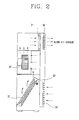
- Figure 2 illustrates an interior portion of a general air conditioner schematically.
- an air conditioner comprises a suction unit 94, an evaporator 70 for evaporating liquid into gas, an indoor suction temperature sensor 93 for sensing indoor temperature, an indoor fan 60, up-and down vane 92 for adjusting the air current blown out from the cooling/heating cycle of the air conditioner to the upper and lower directions and a left-and-right direction vane 91 for adjusting the air current blown out from the cooling/heating cycle of the air conditioner to the left and right directions.
- the indoor suction temperature sensor 93 installed in the suction unit 94 of the air conditioner measures the indoor temperature and turns off the operation of the compressor 80 in case the measured temperature is lower than the minimum value of the setting temperature, or turns on the operation of the compressor 80 in case the measured temperature is higher than the maximum value of the setting temperature. The above operations is repeated to perform cooling operation.
- the indoor suction temperature sensor 93 installed in the suction unit 94 of the air conditioner measures the indoor temperature and turns off the operation of the compressor 80 in case the measured temperature is higher than the minimum value of the setting temperature, or turns on the operation of the compressor 80 in case the measured temperature is lower than the maximum value of the setting temperature. The above operations are repeated to perform heating operation.
- the up-and-down direction vane 92 and left-and-right direction vane 91 rotates to adjust a direction of the blown out cooling heating air current and the indoor temperature repeatedly rise and fall between the maximum and minimum values of the setting temperature.
- the conventional air conditioner collectively controls the temperature, humidity and air current, according to the temperature set by the user.
- the temperature, humidity, air current that the user feels pleasantness are different, and accordingly, when the temperature, humidity, air current of the air conditioner is controlled by the user's setting temperature as conventionally, there can occur a case that the user does not feel pleasantness.
- the present invention provides an apparatus and method for controlling operation of an air conditioner, capable of improving pleasantness of users by performing cooling or heating air conditioning control, by calculating cooling or heating indoor temperature, air current and humidity, according to the respective characteristic of the user in case of cooling or heating air conditioning of the air conditioner.
- Another object of the present invention is to provide an apparatus and method for controlling operation of an air conditioner, capable of conveniently inputting or correcting the personal condition information, according to the characteristics of the respective users by storing various personal conditioning information and data in the air conditioner using a remote controller, PC and the mobile communication terminal.
- an apparatus for controlling operation of an air conditioner comprising a display unit for displaying various question data in order to obtain a personal air conditioning information, an input unit for inputting personal air conditioning information corresponding to the question data displayed on the display unit and a microcomputer for calculating a personal characteristic value from the personal air conditioning information inputted from the input unit, and controlling an air conditioner by calculating indoor temperature/air current/humidity according to the calculated characteristic value in air cooling or heating.
- a method for controlling operation of an air conditioner comprising the steps of displaying various question data for detecting personal air conditioning information when a personal characteristic initializing mode is inputted, inputting personal air conditioning information corresponding to the various question data, storing the inputted personal air conditioning information, calculating personal characteristic value by the response data corresponding to the inputted personal air conditioning information, calculating indoor temperature/air current/humidity according to air cooling or heating by the calculated personal characteristic value and controlling the air conditioner by the calculated indoor temperature, air current and humidity according to air cooling or heating.
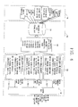
- Figure 3 illustrates a block diagram showing the composition of an air conditioner in accordance with the present invention.
- the air conditioner comprises: an indoor temperature sensor unit 100 for sensing indoor temperature, a display unit 120 for displaying question data, an input unit 110 for inputting air conditioning information of a user, a microcomputer 130 for calculating personal characteristic value using the air conditioning information inputted from the input unit 110, calculating cooling or heating indoor temperature, air current and humidity by the calculated personal characteristic value and controlling cooling and heating air conditioning according to the calculated value, an indoor fan driving unit 140 for outputting an indoor fan 180 driving signal by the control signal of the microcomputer 130, an indoor fan 180 for driven by the driving signal outputted from the indoor fan driving unit 140, an up-and-down vane driving unit 150 for outputting an up-and-down direction driving signal by the control signal of the microcomputer 130, an up-and-down vane 190 for adjusting the cooling or heating air current to the upper and lower direction by the control signal outputted from the up-and-down vane driving unit 150, a left-and-right vane driving unit 160 for outputting a left-and-right direction driving signal
- the input unit 110 can use a remote controller, computer and a mobile communication terminal so that the user can input one's own air conditioning information according to questions for the personal characteristics.
- Figure 4 illustrates a block diagram showing the composition of the microcomputer of Figure 3.
- the microcomputer 130 comprises a characteristic data storage unit 131 for storing the question data and response data corresponding to the respective question data in advance, storing the response data values corresponding to the air conditioning information data inputted by the user and outputting the stored response data values, a characteristic data calculator 132 for calculating the personal characteristic value by the response data value outputted from the characteristic data storage unit 131, a control calculation unit 133 for calculating indoor temperature, air current and humidity by the personal characteristic value calculated from the characteristic data calculator 132 and a control unit 134 for outputting the control signal for driving the compressor driving unit 170, indoor fan driving unit 140, up-and-down vane driving unit 150 and left-and-right vane direction unit 160, by indoor temperature, air current and humidity calculated from the control calculation unit 133.
- the control calculation unit 133 comprises an indoor temperature calculator 133-1 for calculating indoor temperature by the personal characteristic value calculated by the characteristic value calculator 132 and outputting the indoor temperature control signal according to the calculated indoor temperature, an indoor air current calculator 133-2 for calculating the indoor air current by the personal characteristic value and outputting the indoor air current control signal according to the calculated indoor air current value and an indoor humidity calculator 133-3 for calculating the indoor humidity by the personal characteristic value and outputting the indoor humidity control signal according to the calculated indoor humidity value.
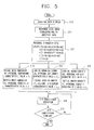
- Figure 5 illustrates a flowcharts the operating of the air conditioner in accordance with the present invention
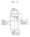
- Figure 6 illustrates schematically a remote controller in accordance with a first embodiment of an input unit of Figure 3.
- the microcomputer 130 displays question data on the display unit 120 to detect personal characteristics.
- the question data include coldness, heat, humidity, air current, clothes amount in case of air cooling, clothes amount in case of air heating, age, sex, activity, smoking/nonsmoking and the like.
- the question data can be varied more such as copy efficiency, cleanness and the like.
- the input unit 110 is composed of a remote controller for inputting data using buttons from the remote distance and comprises a display unit 120 for displaying question data, a mode selection key 111 for operating a personal characteristic initializing mode for inputting personal air conditioning information to the air conditioner, or a personal characteristic mode for selecting among the stored data, and selection keys 113, 114 and 115 for inputting air conditioning information of the user according to the respective questions displayed on the display unit 120.
- the selection keys 113, 114 and 115 were illustrated with just 3 keys of large, medium and small in accordance with the embodiment of the present invention, but the keys can be composed of 3 or more keys.
- the microcomputer 130 displays a question, that ' strong for cold?' on the display unit 120 of the remote controller, then the user determines whether he or she is strong for cold and selects one of the selection keys 113,114 and 115. (S11)
- the selected data is inputted in the characteristic data storage unit 131 of the microcomputer 130 and the characteristic storage unit 131 stores the response data value corresponding to the inputted data among the stored response data value.
- the microcomputer 130 displays questions such as 'strong for heat?', 'strong for humidity?', 'clothes amount in case of air cooling?', 'clothes amount in case of air heating?', 'age of the user?', 'sex of the user?', 'current activity amount?' and 'smoking or nonsmoking?' on the display unit 120, the user selects a preferred key among large/medium/small selection keys 113, 114 and 115 to all questions but the questions on sex and smoking. (S11)
- the large key 113 is selected, and in case the user is female and a nonsmoker, the small key 115 is selected.
- the microcomputer 130 stores the response data value corresponding to the personal air conditioning information data inputted by the user among the response data values stored in the characteristic data storage unit 131 in advance.
- the characteristic data calculator 132 in the microprocessor 130 reads the value stored in the characteristic data storage unit 131 and calculates the personal characteristic value. (S12)
- Al is a response data value for the key selected when the user feels a cold.
- An is a response data value for the key selected when the user feels a normal for cold.
- Ad is a response data value for the key selected when the user is not feels the cold.
- Bl is a response data value for the key selected when the user feels a heat.
- Bn is a response data valuefor the key selected when the user feels a normal for heat.
- Bd is a response data value for the key selected when the user is not feels the heat.
- Cl is a response data value for the key selected when the user feels a strong for humidity.
- Cn is a response data value for the key selected when the user feels a normal for humidity
- Cd is a response data value for the key selected when the user feels a weak for humidity.
- Dl is a response data value for the key selected when the user feels a strong for air current.
- Dn is a response data value for the key selected when the user feels a normal for air current.
- Dd is a response data value for the key selected when the user feels a weak for air current.
- El is a response data value according to a case that the clothes of the user is thick in air cooling
- En is a response data value according to the case that the clothes of the user is normal in air cooling.
- Ed is a response data value according to the case that the clothes of the user is slim in air cooling.
- Fl is a response data value according to the case that the clothes of the user is thick in air heating.
- Fn is a response data value according to the case that the clothes of the user is normal in air heating.
- Fd is a response data value according to the case that the clothes of the user is slim in air heating.
- Gl is a response data value according to the case that the user does much activities.
- G2 is a response data value according to the case that the user does normal activities amount is normal.
- G3 is a response data value according to the case that the user does a little activity.
- H1 is a response data value according to the case that the sex of user is male.
- H2 is a response data value according to the case that the sex of user is female.
- Id is a response data value according to the case that the user is not a smoker.
- the above personal characteristic value is set by a research for measuring temperature, humidity and air current that respondents feel optimum pleasantness varying temperature, air current and humidity after questioning a predetermined number of respondents about the question data.
- the average response value that the largest number of people responded about respective questions is obtained by comparing the response data values of respondents who feel optimum pleasantness under the condition of similar temperature, air current and humidity and setting the response data value to the respective question data according to the temperature, air current and humidity of the respective levels.
- the characteristic data calculator 132 of the microcomputer 130 calculates the personal characteristic value using the response data and inputs the calculated personal characteristic vale into the indoor temperature calculator 133-1, the indoor air current calculator 133-2 and the indoor humidity calculator 133-3 of the control calculation unit 133.
- the indoor temperature calculator 133-1 outputs an indoor temperature control signal by calculating the cooling or heating indoor temperature that the user can feel the optimum pleasantness in air cooling or heating, by the above inputted personal characteristic value. (S13)
- the indoor air current calculator 133-2 outputs a control signal by calculating the cooling or heating indoor air current in air cooling or heating, by the personal characteristic value inputted from the characteristic data calculator 132. (S14)
- the indoor humidity calculator 133-3 outputs an indoor humidity control signal by calculating the cooling or heating indoor humidity in air cooling or heating, by the personal characteristic value inputted from the characteristic data calculator 132. (S15)
- the control signals of cooling or heating indoor temperature, air current and humidity outputted from the indoor temperature calculator 133-1, the indoor air current calculator 133-2 and the indoor humidity calculator 133-3 are outputted to the control unit 134.
- the control unit 134 outputs control signals for controlling driving of the compressor driving unit 170, indoor fan driving unit 140, up-and-down vane driving unit 150 and left-and-right vane driving unit 160, by the above inputted control signal.
- the compressor 170, indoor fan 180, up-and-down vane 190 and left-and-right vane 200 are controlled and accordingly temperature, air current and humidity are adjusted according to the respective users, thus to feel the optimum pleasantness of the user.
- the respective response data corresponding to the question data are stored in the characteristic data storage unit 131 and the stored data value can be used by reading it in case of selecting the personal characteristic mode.
- the user selects a name corresponding to the user using the selection keys 113, 114 and 115 and mode selection key 111 of the remote controller.
- the microcomputer 130 reads the response data value corresponding to the name, calculates the personal characteristic value and obtains the indoor temperature, air current and humidity in case of air cooling or heating by the personal characteristic value, thus to control the air conditioner.
- the data can be simply changed by selecting the corresponding question and then re-inputting the response data of the corresponding question to change the corresponding response data value. Accordingly, the air conditioner can be easily controlled by the living conditions, thus to improve pleasantness of the user.
- the input unit 110 can use a computer and mobile communication terminal as well as a remote controller.
- the input unit 110 will be described in detail with reference to Figures 7, 8 and 9.
- Figure 7 illustrates schematically the connection between the air conditioner and the internet.
- a modem is mounted is built-in the air conditioner to directly connect the air conditioner to the internet.
- the air conditioner Since the air conditioner is directly connected to the internet, data on the personal air conditioning information included in the related sites are downloaded using the remote controller which is a remote distance control means.
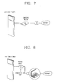
- Figure 8 illustrates schematically the connection between the air conditioner and a computer in accordance with a second embodiment of the input unit of Figure 3.
- the air conditioner is connected to a personal computer (PC) via a cable and receives personal air conditioning data from the PC.
- PC personal computer
- the user connects to an internet site though a PC and responds to the question data of the personal air conditioning information, such as cold, heat, humidity, air current, clothes amount in case of air cooling, clothes amount in case of air heating, activity, sex, smoking/nonsmoking and the like. Then, the user downloads the responded personal air conditioning information to the PC through the internet.
- the personal air conditioning information such as cold, heat, humidity, air current, clothes amount in case of air cooling, clothes amount in case of air heating, activity, sex, smoking/nonsmoking and the like.
- the PC transmits the downloaded personal air conditioning information to the air conditioner via the cable (RS232C).
- personal air conditioning information of two or more users can be transmitted at a time.
- the microcomputer 130 stores the response data value corresponding to the transmitted personal air conditioning information data, calculates the personal characteristic value by the stored response data value and controls the air conditioner by adjusting indoor temperature, air current and humidity to the preferred level for the respective users in air cooling and heating.
- Figure 9 illustrates schematically the connection between the air conditioner and a mobile communication terminal in accordance with a third embodiment of the input unit of Figure 3.
- a mobile communication terminal can be used.
- a bluetooth module is built-in the air conditioner for carrying out local area communication by the mobile communication terminal.
- the mobile communication terminal in which the bluetooth is installed carry out local area communication and downloads personal air conditioning information and data through the internet, thus to perform air cooling or heating and dehumidifying functions of the air conditioner.
- temperature, air current and humidity according to the respective users can be calculated by the response data inputted by the user and driving of the compressor 210, indoor fan 180, up-and-down vane 190 and left-and-right vane 200 can be controlled, thus to improve a sense of pleasantness and satisfaction of the users.
- the data can be corrected by inputting the data corresponding to the portion to be corrected and accordingly, the user can simply and easily control temperature, air current and humidity preferably.
- the data for inputting easily the personal air conditioning information using the PC, remote controller and the mobile communication terminal can be downloaded by mounting a modem in the air conditioner and connecting to the internet, and thereby the personal information can be easily stored in the air conditioner.
Applications Claiming Priority (4)
| Application Number | Priority Date | Filing Date | Title |
|---|---|---|---|
| KR2001044910 | 2001-07-25 | ||
| KR1020010044909A KR20030010123A (ko) | 2001-07-25 | 2001-07-25 | 공기조화기 및 그의 운전제어방법 |
| KR1020010044910A KR20030010124A (ko) | 2001-07-25 | 2001-07-25 | 인터넷용 공기조화기 |
| KR2001044909 | 2001-07-25 |
Publications (2)
| Publication Number | Publication Date |
|---|---|
| EP1279902A2 true EP1279902A2 (fr) | 2003-01-29 |
| EP1279902A3 EP1279902A3 (fr) | 2004-10-13 |
Family
ID=26639261
Family Applications (1)
| Application Number | Title | Priority Date | Filing Date |
|---|---|---|---|
| EP02291099A Withdrawn EP1279902A3 (fr) | 2001-07-25 | 2002-05-02 | Procédé et dispositif de la commande du fonctionnement d'un appareil de climatisation |
Country Status (3)
| Country | Link |
|---|---|
| EP (1) | EP1279902A3 (fr) |
| JP (1) | JP3694274B2 (fr) |
| CN (1) | CN100445656C (fr) |
Cited By (8)
| Publication number | Priority date | Publication date | Assignee | Title |
|---|---|---|---|---|
| EP1680633A1 (fr) * | 2003-10-24 | 2006-07-19 | Andrew C. Fuller | Systeme de controle |
| WO2011028889A3 (fr) * | 2009-09-02 | 2011-09-09 | Optimum Energy, Llc | Régulation des conditions ambiantes pour système de chauffage, ventilation et climatisation |
| CN102235727A (zh) * | 2010-04-29 | 2011-11-09 | 深圳市西谷制冷设备有限公司 | 恒温恒湿装置及控制方法 |
| CN104456868A (zh) * | 2014-11-19 | 2015-03-25 | 珠海格力电器股份有限公司 | 空调控制系统 |
| EP3045829A1 (fr) * | 2015-01-19 | 2016-07-20 | Halton OY | Régulation des conditions ambiantes intérieures |
| CN113932296A (zh) * | 2021-12-03 | 2022-01-14 | 河南新飞制冷器具有限公司 | 一种新型制冷装置和控制方法 |
| US11294343B2 (en) | 2016-01-12 | 2022-04-05 | Optimum Energy, Llc | Predictive free cooling |
| WO2022126222A1 (fr) * | 2020-12-18 | 2022-06-23 | Robert Bosch Limitada | Procédé et système de gestion de confort thermique dans des environnements climatisés |
Families Citing this family (14)
| Publication number | Priority date | Publication date | Assignee | Title |
|---|---|---|---|---|
| CN1967075B (zh) * | 2005-11-18 | 2010-05-05 | 乐金电子(天津)电器有限公司 | 复合式空调器系统 |
| KR100826721B1 (ko) * | 2006-08-03 | 2008-04-30 | 엘지전자 주식회사 | 천정형 공기 조화기 및 그 제어방법 |
| JP4827798B2 (ja) * | 2007-06-13 | 2011-11-30 | 三菱電機株式会社 | 空調用リモートコントローラおよび空気調和機並びに空気調和システム |
| JP2009264608A (ja) * | 2008-04-22 | 2009-11-12 | Mitsubishi Electric Corp | 空気調和機 |
| KR101267633B1 (ko) * | 2013-01-28 | 2013-05-27 | 박경화 | 습도를 기준으로 하는 최적의 체감 온도 제어 시스템 |
| CN104566774A (zh) * | 2013-10-28 | 2015-04-29 | 广东美的集团芜湖制冷设备有限公司 | 一种空调器的控制方法 |
| KR102157072B1 (ko) * | 2013-12-03 | 2020-09-17 | 삼성전자 주식회사 | 공조장치 또는 공조시스템의 온도 제어장치 및 방법 |
| CN104633866B (zh) * | 2015-02-15 | 2017-06-16 | 重庆大学 | 基于环境参数和人体生理参数的热舒适度测评系统 |
| CN106052034B (zh) * | 2015-10-30 | 2019-01-22 | 广东美的制冷设备有限公司 | 一种基于脸部特征进行空调控制的方法、系统及空调 |
| CN105276765B (zh) * | 2015-10-30 | 2018-04-17 | 广东美的制冷设备有限公司 | 一种利用身型数据控制空调的方法及系统 |
| CN106500243B (zh) * | 2016-10-18 | 2019-01-18 | 珠海格力电器股份有限公司 | 控制空调输出温度的方法和装置 |
| JP7136575B2 (ja) | 2018-03-30 | 2022-09-13 | 三菱重工サーマルシステムズ株式会社 | 空調システム及び制御方法 |
| CN111207497A (zh) * | 2018-11-22 | 2020-05-29 | 青岛海尔空调器有限总公司 | 用于空调的控制方法 |
| CN109990437B (zh) * | 2019-03-07 | 2021-05-28 | 上海正阳电子有限公司 | 一种空调器的区域温度控制方法 |
Citations (5)
| Publication number | Priority date | Publication date | Assignee | Title |
|---|---|---|---|---|
| US5613369A (en) * | 1994-09-28 | 1997-03-25 | Kabushiki Kaisha Toshiba | Air conditioner and control method for an air conditioner |
| US5651264A (en) * | 1993-06-29 | 1997-07-29 | Siemens Electric Limited | Flexible process controller |
| JPH09264594A (ja) * | 1996-03-28 | 1997-10-07 | Mitsubishi Electric Corp | 空気調和機のワイヤレスリモコン装置 |
| EP0908684A2 (fr) * | 1997-10-08 | 1999-04-14 | Carrier Corporation | Unité de commande à distance |
| EP1014009A2 (fr) * | 1998-12-25 | 2000-06-28 | Mitsubishi Denki Kabushiki Kaisha | Dispositif de conditionnement d'air |
-
2002
- 2002-05-02 EP EP02291099A patent/EP1279902A3/fr not_active Withdrawn
- 2002-05-14 JP JP2002138336A patent/JP3694274B2/ja not_active Expired - Fee Related
- 2002-07-23 CN CNB021268037A patent/CN100445656C/zh not_active Expired - Fee Related
Patent Citations (5)
| Publication number | Priority date | Publication date | Assignee | Title |
|---|---|---|---|---|
| US5651264A (en) * | 1993-06-29 | 1997-07-29 | Siemens Electric Limited | Flexible process controller |
| US5613369A (en) * | 1994-09-28 | 1997-03-25 | Kabushiki Kaisha Toshiba | Air conditioner and control method for an air conditioner |
| JPH09264594A (ja) * | 1996-03-28 | 1997-10-07 | Mitsubishi Electric Corp | 空気調和機のワイヤレスリモコン装置 |
| EP0908684A2 (fr) * | 1997-10-08 | 1999-04-14 | Carrier Corporation | Unité de commande à distance |
| EP1014009A2 (fr) * | 1998-12-25 | 2000-06-28 | Mitsubishi Denki Kabushiki Kaisha | Dispositif de conditionnement d'air |
Non-Patent Citations (1)
| Title |
|---|
| PATENT ABSTRACTS OF JAPAN vol. 1998, no. 02, 30 January 1998 (1998-01-30) & JP 09 264594 A (MITSUBISHI ELECTRIC CORP), 7 October 1997 (1997-10-07) * |
Cited By (13)
| Publication number | Priority date | Publication date | Assignee | Title |
|---|---|---|---|---|
| EP1680633A4 (fr) * | 2003-10-24 | 2006-11-08 | Andrew C Fuller | Systeme de controle |
| EP1680633A1 (fr) * | 2003-10-24 | 2006-07-19 | Andrew C. Fuller | Systeme de controle |
| US11438189B2 (en) | 2009-09-02 | 2022-09-06 | Optimum Energy Llc | Environmental control for HVAC system |
| WO2011028889A3 (fr) * | 2009-09-02 | 2011-09-09 | Optimum Energy, Llc | Régulation des conditions ambiantes pour système de chauffage, ventilation et climatisation |
| US8897921B2 (en) | 2009-09-02 | 2014-11-25 | Ian Dempster | Environmental control for HVAC system |
| CN102235727A (zh) * | 2010-04-29 | 2011-11-09 | 深圳市西谷制冷设备有限公司 | 恒温恒湿装置及控制方法 |
| CN104456868A (zh) * | 2014-11-19 | 2015-03-25 | 珠海格力电器股份有限公司 | 空调控制系统 |
| CN104456868B (zh) * | 2014-11-19 | 2017-04-12 | 珠海格力电器股份有限公司 | 空调控制系统 |
| EP3045829A1 (fr) * | 2015-01-19 | 2016-07-20 | Halton OY | Régulation des conditions ambiantes intérieures |
| US10578326B2 (en) | 2015-01-19 | 2020-03-03 | Halton Oy | Controlling indoor environmental condition |
| US11294343B2 (en) | 2016-01-12 | 2022-04-05 | Optimum Energy, Llc | Predictive free cooling |
| WO2022126222A1 (fr) * | 2020-12-18 | 2022-06-23 | Robert Bosch Limitada | Procédé et système de gestion de confort thermique dans des environnements climatisés |
| CN113932296A (zh) * | 2021-12-03 | 2022-01-14 | 河南新飞制冷器具有限公司 | 一种新型制冷装置和控制方法 |
Also Published As
| Publication number | Publication date |
|---|---|
| CN100445656C (zh) | 2008-12-24 |
| JP2003050040A (ja) | 2003-02-21 |
| EP1279902A3 (fr) | 2004-10-13 |
| JP3694274B2 (ja) | 2005-09-14 |
| CN1399106A (zh) | 2003-02-26 |
Similar Documents
| Publication | Publication Date | Title |
|---|---|---|
| EP1279902A2 (fr) | Procédé et dispositif de la commande du fonctionnement d'un appareil de climatisation | |
| KR101244031B1 (ko) | 공기 조화기 및 그 제어 방법 | |
| KR100557043B1 (ko) | 냉난방기의 건강 제습 운전방법 | |
| JPH08254363A (ja) | 空調制御装置 | |
| CN113574323B (zh) | 空调系统 | |
| JP2020193759A (ja) | 空気調和システム | |
| KR100239576B1 (ko) | 공기조화기의 드라이 운전장치 및 그 제어방법 | |
| JP2003035449A (ja) | 空気調和装置及び空気調和装置の制御情報の提供システム及び提供方法 | |
| JP5478397B2 (ja) | 空気調和機 | |
| US11835247B2 (en) | Air conditioning control device and air conditioning apparatus | |
| KR20060121030A (ko) | 실시간 전력 소비량 표시기능을 갖는 에어컨 및 그표시방법 | |
| JP2001355890A (ja) | 空気調和機 | |
| JP6746246B2 (ja) | 空気調和機 | |
| KR101913511B1 (ko) | 공기조화기의 제어방법 | |
| KR100378802B1 (ko) | 공기조화기의 개별 공조방법 | |
| JP3855545B2 (ja) | 空気調和機 | |
| KR20030010123A (ko) | 공기조화기 및 그의 운전제어방법 | |
| KR100286554B1 (ko) | 공기조화기의절전운전제어장치및그방법 | |
| KR100461655B1 (ko) | 에어컨의 실내팬제어방법 | |
| JP3500128B2 (ja) | 空気調和装置の制御方法及び空気調和装置 | |
| KR100304553B1 (ko) | 히트펌프공기조화기와그난방운전을위한제어방법 | |
| KR100286555B1 (ko) | 공기조화기의절전운전표시장치및그방법 | |
| KR20050078887A (ko) | 공기조화기의 소비전력 표시장치 및 방법 | |
| JPH05322275A (ja) | 多室形空気調和システム | |
| KR100197736B1 (ko) | 공기조화기의 토출기류 제어장치 및 그 방법 |
Legal Events
| Date | Code | Title | Description |
|---|---|---|---|
| PUAI | Public reference made under article 153(3) epc to a published international application that has entered the european phase |
Free format text: ORIGINAL CODE: 0009012 |
|
| AK | Designated contracting states |
Designated state(s): AT BE CH CY DE DK ES FI FR GB GR IE IT LI LU MC NL PT SE TR |
|
| AX | Request for extension of the european patent |
Extension state: AL LT LV MK RO SI |
|
| PUAL | Search report despatched |
Free format text: ORIGINAL CODE: 0009013 |
|
| AK | Designated contracting states |
Kind code of ref document: A3 Designated state(s): AT BE CH CY DE DK ES FI FR GB GR IE IT LI LU MC NL PT SE TR |
|
| AX | Request for extension of the european patent |
Extension state: AL LT LV MK RO SI |
|
| 17P | Request for examination filed |
Effective date: 20050225 |
|
| AKX | Designation fees paid |
Designated state(s): DE FR GB |
|
| 17Q | First examination report despatched |
Effective date: 20070221 |
|
| STAA | Information on the status of an ep patent application or granted ep patent |
Free format text: STATUS: THE APPLICATION IS DEEMED TO BE WITHDRAWN |
|
| 18D | Application deemed to be withdrawn |
Effective date: 20070904 |