EP1279873B1 - Ventil - Google Patents
Ventil Download PDFInfo
- Publication number
- EP1279873B1 EP1279873B1 EP02090274A EP02090274A EP1279873B1 EP 1279873 B1 EP1279873 B1 EP 1279873B1 EP 02090274 A EP02090274 A EP 02090274A EP 02090274 A EP02090274 A EP 02090274A EP 1279873 B1 EP1279873 B1 EP 1279873B1
- Authority
- EP
- European Patent Office
- Prior art keywords
- throttle
- piston
- section
- throttle piston
- taper
- Prior art date
- Legal status (The legal status is an assumption and is not a legal conclusion. Google has not performed a legal analysis and makes no representation as to the accuracy of the status listed.)
- Expired - Lifetime
Links
- 230000007423 decrease Effects 0.000 claims abstract description 3
- 210000003813 thumb Anatomy 0.000 claims description 3
- 230000001419 dependent effect Effects 0.000 claims 1
- 239000011796 hollow space material Substances 0.000 claims 1
- 238000006073 displacement reaction Methods 0.000 description 3
- 238000001595 flow curve Methods 0.000 description 2
- 230000000750 progressive effect Effects 0.000 description 2
- 238000007789 sealing Methods 0.000 description 2
- 230000001133 acceleration Effects 0.000 description 1
- 230000003247 decreasing effect Effects 0.000 description 1
- 210000003746 feather Anatomy 0.000 description 1
- 238000004519 manufacturing process Methods 0.000 description 1
- 239000002184 metal Substances 0.000 description 1
- 230000003716 rejuvenation Effects 0.000 description 1
Images


Classifications
-
- F—MECHANICAL ENGINEERING; LIGHTING; HEATING; WEAPONS; BLASTING
- F16—ENGINEERING ELEMENTS AND UNITS; GENERAL MEASURES FOR PRODUCING AND MAINTAINING EFFECTIVE FUNCTIONING OF MACHINES OR INSTALLATIONS; THERMAL INSULATION IN GENERAL
- F16K—VALVES; TAPS; COCKS; ACTUATING-FLOATS; DEVICES FOR VENTING OR AERATING
- F16K3/00—Gate valves or sliding valves, i.e. cut-off apparatus with closing members having a sliding movement along the seat for opening and closing
- F16K3/30—Details
- F16K3/34—Arrangements for modifying the way in which the rate of flow varies during the actuation of the valve
-
- F—MECHANICAL ENGINEERING; LIGHTING; HEATING; WEAPONS; BLASTING
- F16—ENGINEERING ELEMENTS AND UNITS; GENERAL MEASURES FOR PRODUCING AND MAINTAINING EFFECTIVE FUNCTIONING OF MACHINES OR INSTALLATIONS; THERMAL INSULATION IN GENERAL
- F16K—VALVES; TAPS; COCKS; ACTUATING-FLOATS; DEVICES FOR VENTING OR AERATING
- F16K3/00—Gate valves or sliding valves, i.e. cut-off apparatus with closing members having a sliding movement along the seat for opening and closing
- F16K3/22—Gate valves or sliding valves, i.e. cut-off apparatus with closing members having a sliding movement along the seat for opening and closing with sealing faces shaped as surfaces of solids of revolution
- F16K3/24—Gate valves or sliding valves, i.e. cut-off apparatus with closing members having a sliding movement along the seat for opening and closing with sealing faces shaped as surfaces of solids of revolution with cylindrical valve members
Definitions
- the invention relates to a pneumatic throttle valve, according to the preamble of Claim 1.
- Pneumatic throttle valves are known, for example from DE 199 32 982 A1. These have a throttle channel in the form of an inner cylinder, which one Inflow opening and an outflow opening connects together.
- a cylindrical throttle piston is arranged in its longitudinal direction from the outside can be moved here.
- the throttle piston can usually be between two Move end positions.
- the throttle piston is also transverse to its longitudinal direction a radial taper, which in the area of a throttle channel edge Forms an annular gap as an overflow passage.
- the annular gap cross section is from depending on the axial position of the throttle piston.
- DE 33 42 405 C2 discloses a throttle valve in which the throttle piston itself and the opposite contact surface are conical, what a degressive increase in the cross-section when moving the Throttle piston causes from its starting position to its end position.
- the Cross-sectional area as a function of the piston travel causes a in this throttle valve degressive characteristic. It only allows a soft start in the Moment of opening and closing because of the conical shape of the Throttle piston and the opposite contact surface of the usual occurring suction and thereby an additional acceleration of the piston prevented becomes.
- Throttle valve does not allow light loads to be lifted and controlled with care can be lowered.
- FR 1 526 193 discloses a hydraulic valve with a housing, with a Inflow opening and an outflow opening, which are connected to one another via a throttle duct are connected and with the interposition of a throttle piston in the Throttle channel longitudinally displaceable between a starting position and one End position is arranged and a taper transverse to its longitudinal direction in Has the shape of a groove-like depression which with the throttle channel Overflow passage forms, wherein the taper is formed such that the Overflow cross-section increases progressively when the throttle piston is moved.
- DE 1 062 507 describes a valve cone for control valves with a through Valve seat protruding, tapering towards its free end towards the rotating body with recesses widening towards the free end.
- the Rotary body consists of a the size of the passage cross section Function of the throttle body changing the valve lift height and its recess an approximately V-shaped slot that runs transversely through the rotating body, the Edge curves converging symmetrically to the longitudinal axis of the rotating body according to the desired relationship between valve lift and Cross-section release are shaped.
- the object of the invention is to provide a passage valve for a hoist of the type Propose balancers that enable sensitive control.
- a simple design provides that one end of the throttle piston protruding from the housing forms an actuator that by a Operator for longitudinal displacement of the throttle piston using the thumb can be actuated.
- the manufacturing effort is relatively low if the throttle piston has a cylinder a radial taper that progressively decreases in one of its longitudinal directions, and the throttle channel has a cylindrical shape corresponding to the throttle piston Forms cavity.
- Fig. 1 shows a housing 1 in which two pneumatic passage valves one pneumatic balancing hoist in two different working positions (closed, partially open) are shown, with compressed air as the flow medium is used.
- Each passage valve is with an inflow opening 2 and one Outflow opening 3 provided for the compressed air, both openings 2, 3 via one Throttle channel 4 are interconnected.
- a throttle piston 5 is interposed, which between a Starting position and an end position in the throttle channel 4 is arranged. Referring to Fig. 1, the left throttle valve is in its Starting position, so it's closed.
- the throttle piston 5 is essentially a metal cylinder in its middle Area has a radial taper 6 (see. Fig. 4).
- the throttle channel 4 is a Throttle piston 5 corresponding inner cylinder, so it is cylindrical Cavity formed.
- the two passage valves protrude with respect to FIG. 1 its upper end out of the housing 1, the upper end as Actuator for an operator is used.
- On the opposite lower one The end of the throttle piston 5 is supported on the housing 1 by a spring 7.
- the by means of the thumb of an operator longitudinally displaceable (operable) Throttle piston 5 controls the volume flow between the inflow opening 2 and the Outflow opening 3.
- the taper 7, which with the throttle duct 5 is used for this purpose Overflow passage (flow ring gap) 8 forms. From Fig. 1 it can be seen that the Overflow cross section depends in each case on the position of the throttle piston 5.
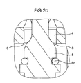
- FIG. 2a shows an enlarged view in the area of the flow passage 8 according to FIG Fig. 1, Fig. 2b shows this with the passage valve closed.
- the Overflow passage 8 is in Fig. 2b by means of a sealing ring 8a and a ring system 8b tightly closed.
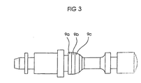
- FIG. 3 shows the throttle piston 5 according to FIG. 1.
- FIG. 4 shows a middle area of the throttle piston 5 in an enlarged view.
- the throttle piston 5 has three control sections 9 on, namely a cylindrical initial portion 9a, the The outer diameter is somewhat smaller than the inner diameter of the throttle duct 4. In this way, an annular gap 10 is formed, which the volume flow due to effective length.
- the overflow passage 8 can be in this area also referred to as residual overflow.
- a central section 9b adjoins the initial section 9a Initial area of the taper 6 includes. Because of the increasing radial Taper 6 (decreasing diameter per unit length of throttle piston 5) the overflow cross section of the overflow passage 8 also increases progressively. He becomes 5 depending on the longitudinal displacement of the throttle valve disproportionately larger.
- the middle section 9b is adjoined by an end section 9c in the form of a Cone piece with a steep cone angle compared to the angle of rise of the middle section 9b.
- an end section 9c in the form of a Cone piece with a steep cone angle compared to the angle of rise of the middle section 9b.
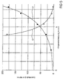
- FIG. 5 An associated flow characteristic of the passage valve is shown in FIG. 5, wherein the flow (flow curve 11) and that corresponding to the flow Resistance coefficient (resistance coefficient curve 12) as a function of Longitudinal displacement of the throttle piston 5 are shown.
Description
- einen zylindrischen Anfangsabschnitt, dessen Außendurchmesser kleiner als der Innendurchmesser des Hohlraums ist, so dass ein Ringspalt gebildet wird, der den Überströmdurchlass (Restüberströmdurchlass) im Bereich der Ausgangsstellung bildet,
- einen mittleren Abschnitt, der den Anfangsbereich der Verjüngung umfasst, der den progressiv zunehmenden Überströmquerschnitt bildet,
- einen Endabschnitt in Form eines Konusstücks mit steilem Konuswinkel zur Ausnutzung des größtmöglichen Druckgefälles zwischen der Zuströmöffnung und der Abströmöffnung.
- Fig. 1
- zwei Drosselventile, ein Drosselventil in unbetätigter geschlossener und eines in teilweise offener Stellung,
- Fig. 2a
- den Überströmdurchlass bei teilweise offenem Durchlassventil gemäß Fig. 1 in einer vergrößerten Darstellung,
- Fig. 2b
- den Überströmdurchlass bei geschlossenem Durchlassventil gemäß Fig. 1 in einer vergrößerten Darstellung,
- Fig. 3
- den Drosselkolben gemäß Fig. 1,
- Fig. 4
- einen vergrößerten Ausschnitt des Drosselkolbens gemäß Fig. 3 und
- Fig. 5
- eine Durchflusskennlinie des Durchlassventils gemäß Fig. 1.
- 1
- Gehäuse
- 2
- Zuströmöffnung
- 3
- Abströmöffnung
- 4
- Drosselkanal
- 5
- Drosselkolben
- 6
- Verjüngung
- 7
- Feder
- 8
- Überströmdurchlass
- 8a
- Dichtrings Ringanlage
- 8b
- Ringanlage
- 9
- Längsabschnitt
- 9a
- Anfangsabschnitt
- 9b
- mittlerer Abschnitt
- 9c
- Endabschnitt
- 10
- Ringspalt
- 11
- Durchflusskurve
- 12
- Widerstandsbeiwertkurve
Claims (3)
- Pneumatisches Drosselventil, mit einem Gehäuse,
mit einer Zuströmöffnung und einer Abströmöffnung, die über einen Drosselkanal miteinander verbunden sind,
unter Zwischenschaltung eines Drosselkolbens, der im Drosselkanal längsverschieblich zwischen einer Ausgangsstellung und einer Endstellung angeordnet ist und
quer zu seiner Längsrichtung eine Verjüngung aufweist, die mit dem Drosselkanal einen Überströmdurchlass bildet,
dessen Überströmquerschnitt von der Stellung des Drosselkolbens abhängt, wobei die Verjüngung (6) derart ausgebildet ist,
dass der Überströmquerschnitt beim Verschieben des Drosselkolbens (5) aus seiner Ausgangsstellung in seine Endstellung progressiv zunimmt,
dadurch gekennzeichnet, dass der Drosselkolben (5) drei Längsabschnitte (9) aufweist:einen zylindrischen Anfangsabschnitt (9a), dessen Außendurchmesser kleiner als der Innendurchmesser des Drosselkanals ist, so dass ein Ringspalt (10) gebildet wird, der den Überströmdurchlass (8) im Bereich der Ausgangsstellung bildet,einen mittleren Abschnitt (9b), der den Anfangsbereich der Verjüngung (6) umfasst und der den progressiv zunehmenden Überströmquerschnitt bildet,einen Endabschnitt (9c) in Form eines Konusstücks mit steilem Konuswinkel zur Ausnutzung des größtmöglichen Druckgefälles zwischen der Zuströmöffnung (2) und der Abströmöffnung (3). - Drosselventil nach Anspruch 1,
dadurch gekennzeichnet, dass ein Ende des Drosselkolbens (5) aus dem Gehäuse (1) herausragend ein Betätigungselement bildet, das von einer Bedienperson zur Längsverschiebung des Drosselkolbens (5) mittels des Daumens betätigbar ist. - Drosselventil nach einem der vorhergehenden Ansprüche,
dadurch gekennzeichnet, dass der Drosselkolben (5) ein Zylinder mit einer radialen Verjüngung (6) ist, die in einer seiner Längsrichtungen progressiv abnimmt, und dass der Drosselkanal (4) einen zum Drosselkolben (5) korrespondierenden zylinderförmigen Hohlraum bildet.
Applications Claiming Priority (2)
| Application Number | Priority Date | Filing Date | Title |
|---|---|---|---|
| DE10134972 | 2001-07-24 | ||
| DE10134972A DE10134972A1 (de) | 2001-07-24 | 2001-07-24 | Durchlassventil für Strömungsmedium, insbesondere ein pneumatisches Drosselventil |
Publications (2)
| Publication Number | Publication Date |
|---|---|
| EP1279873A1 EP1279873A1 (de) | 2003-01-29 |
| EP1279873B1 true EP1279873B1 (de) | 2004-11-17 |
Family
ID=7692233
Family Applications (1)
| Application Number | Title | Priority Date | Filing Date |
|---|---|---|---|
| EP02090274A Expired - Lifetime EP1279873B1 (de) | 2001-07-24 | 2002-07-22 | Ventil |
Country Status (6)
| Country | Link |
|---|---|
| US (1) | US6802487B2 (de) |
| EP (1) | EP1279873B1 (de) |
| JP (1) | JP2003156156A (de) |
| AT (1) | ATE282786T1 (de) |
| DE (2) | DE10134972A1 (de) |
| ES (1) | ES2233771T3 (de) |
Cited By (2)
| Publication number | Priority date | Publication date | Assignee | Title |
|---|---|---|---|---|
| EP1998091A2 (de) | 2007-05-29 | 2008-12-03 | Knight Europe GmbH & Co. KG | Pneumatische Steuereinrichtung für ein Drucklufthebezeug |
| US11493061B2 (en) | 2018-02-02 | 2022-11-08 | J.D. Neuhaus Holding Gmbh & Co. Kg | Control valve assembly for an indirect pneumatic control, and method for controlling a working fluid pressure |
Families Citing this family (10)
| Publication number | Priority date | Publication date | Assignee | Title |
|---|---|---|---|---|
| US20060027261A1 (en) * | 2004-08-04 | 2006-02-09 | Plevich Chuck W | Method for repair of regulator poppet and seat |
| US8083936B1 (en) * | 2008-03-03 | 2011-12-27 | Robert Walker | Reducing waste water in reverse osmosis residential drinking water systems |
| BRPI1008098A2 (pt) * | 2009-02-10 | 2016-03-08 | Norgren Gmbh | válvula de gatilho, e, método para regular fluxo de fluido de fluido em uma válvula de gatilho. |
| US9538299B2 (en) | 2009-08-31 | 2017-01-03 | Hewlett-Packard Development Company, L.P. | Acoustic echo cancellation (AEC) with conferencing environment templates (CETs) |
| US10070990B2 (en) | 2011-12-08 | 2018-09-11 | Alcon Research, Ltd. | Optimized pneumatic drive lines |
| KR101326827B1 (ko) * | 2011-12-08 | 2013-11-11 | 주식회사 대철 | 드레인 밸브 장치 및 이를 이용한 에어 세퍼레이션 |
| KR101326830B1 (ko) * | 2011-12-08 | 2013-11-11 | 주식회사 대철 | 드레인 밸브 장치 및 이를 이용한 에어 세퍼레이션 |
| GB2521868A (en) * | 2014-01-07 | 2015-07-08 | Intelligent Energy Ltd | Valve assembly |
| CN205781212U (zh) | 2015-01-19 | 2016-12-07 | 莫恩股份有限公司 | 电子卫生洁具配件 |
| EP3936745B1 (de) | 2015-07-31 | 2024-05-08 | Ecowater Systems LLC | Durchflussbegrenzer mit variablem ablauf |
Family Cites Families (10)
| Publication number | Priority date | Publication date | Assignee | Title |
|---|---|---|---|---|
| US1863712A (en) * | 1930-07-14 | 1932-06-21 | Albert H Byfield | Heating system |
| US2904305A (en) * | 1957-07-11 | 1959-09-15 | Milton A Novotny | Discharge control apparatus for powder fire extinguisher |
| GB992613A (en) * | 1962-08-02 | 1965-05-19 | Messer Adolf Gmbh | A fluid flow control valve |
| GB988894A (en) * | 1962-11-09 | 1965-04-14 | Damic Controls Ltd | Improvements in fluid control valves |
| US3472481A (en) * | 1965-10-22 | 1969-10-14 | Air Reduction | Self-aligning valve closure |
| DE3342405A1 (de) * | 1983-11-24 | 1985-06-05 | Bochumer Eisenhütte Heintzmann GmbH & Co KG, 4630 Bochum | Absperrventil |
| JPS61286602A (ja) * | 1985-06-12 | 1986-12-17 | Junkosha Co Ltd | 流量制御弁 |
| JPH10160034A (ja) * | 1996-11-22 | 1998-06-16 | Nok Corp | ニードルバルブ |
| JP2000249233A (ja) * | 1999-02-26 | 2000-09-12 | Kitz Corp | 流量調整式ニードル弁 |
| DE19932982C2 (de) | 1999-07-14 | 2003-02-13 | Festo Ag & Co | Drosselventil |
-
2001
- 2001-07-24 DE DE10134972A patent/DE10134972A1/de not_active Ceased
-
2002
- 2002-07-22 DE DE50201550T patent/DE50201550D1/de not_active Expired - Lifetime
- 2002-07-22 AT AT02090274T patent/ATE282786T1/de not_active IP Right Cessation
- 2002-07-22 JP JP2002212311A patent/JP2003156156A/ja active Pending
- 2002-07-22 EP EP02090274A patent/EP1279873B1/de not_active Expired - Lifetime
- 2002-07-22 ES ES02090274T patent/ES2233771T3/es not_active Expired - Lifetime
- 2002-07-24 US US10/202,146 patent/US6802487B2/en not_active Expired - Fee Related
Cited By (4)
| Publication number | Priority date | Publication date | Assignee | Title |
|---|---|---|---|---|
| EP1998091A2 (de) | 2007-05-29 | 2008-12-03 | Knight Europe GmbH & Co. KG | Pneumatische Steuereinrichtung für ein Drucklufthebezeug |
| DE102007025059A1 (de) | 2007-05-29 | 2008-12-24 | Knight Europe Gmbh & Co. Kg | Pneumatische Steuereinrichtung für ein Drucklufthebezeug |
| DE102007025059B4 (de) * | 2007-05-29 | 2018-02-01 | Konecranes Lifting Systems Gmbh | Pneumatische Steuereinrichtung für ein Drucklufthebezeug |
| US11493061B2 (en) | 2018-02-02 | 2022-11-08 | J.D. Neuhaus Holding Gmbh & Co. Kg | Control valve assembly for an indirect pneumatic control, and method for controlling a working fluid pressure |
Also Published As
| Publication number | Publication date |
|---|---|
| DE10134972A1 (de) | 2003-02-20 |
| ATE282786T1 (de) | 2004-12-15 |
| ES2233771T3 (es) | 2005-06-16 |
| EP1279873A1 (de) | 2003-01-29 |
| JP2003156156A (ja) | 2003-05-30 |
| DE50201550D1 (de) | 2004-12-23 |
| US20030020036A1 (en) | 2003-01-30 |
| US6802487B2 (en) | 2004-10-12 |
Similar Documents
| Publication | Publication Date | Title |
|---|---|---|
| EP1373753B1 (de) | Gasfeder-dämpfer-einheit für ein kraftfahrzeug | |
| EP0400395B1 (de) | Stossdämpfer | |
| EP1279873B1 (de) | Ventil | |
| EP0325958B1 (de) | Hydraulisch gesteuertes Ventil | |
| DE102008060516B4 (de) | Schwingungsdämpfer | |
| EP0207409A2 (de) | Ventilsystem für steurbare, hydraulische Schwingungsdämpfer | |
| DE3810309A1 (de) | Hydraulisch daempfendes gummilager | |
| DE3519034C2 (de) | ||
| EP0804696A1 (de) | Vorgesteuertes proportional-druckbegrenzungsventil | |
| WO2022175253A1 (de) | Dämpfventileinrichtung mit progressiver dämpfkraftkennlinie | |
| DE102009002003A1 (de) | Druckregelventil, insbesondere für ein Automatikgetriebe in einem Kraftfahrzeug | |
| DE3322020C2 (de) | Ausblaseinrichtung für Ausstoß- und Ablaufrohre von U-Booten | |
| EP1090240B1 (de) | Druckbegrenzungsventil | |
| DE102010060792A1 (de) | Hydraulischer Dämpfer | |
| EP0863342B1 (de) | Drucksteuerventil | |
| DE102007008621A1 (de) | Ventilbaugruppe | |
| DE3601445A1 (de) | Hydropneumatische federung mit lastabhaengiger daempfungssteuerung | |
| EP1717451A2 (de) | Druckmittelbetätigter Arbeitszylinder | |
| EP0160639A1 (de) | Servolenkung, insbesondere für kraftfahrzeuge. | |
| EP0255668B1 (de) | Vorrichtung zur hydraulischen Steuerung von Hubventilen | |
| DE102019218401B3 (de) | Lasthalteventil, Lasthaltventilset und Verfahren zur Montage eines Lasthalteventils | |
| DE4423526C1 (de) | Schwingungsdämpfer mit verstellbarer Dämpfkraft | |
| DE4119297C2 (de) | Hydraulische Ventileinrichtung zur Steuerung des Leerlaufs, der Druckbegrenzung und der Lastdruckkompensation | |
| EP1910721B1 (de) | 3-wegeventil | |
| DE3828025A1 (de) | Daempfungssystem fuer fluid-zylinder |
Legal Events
| Date | Code | Title | Description |
|---|---|---|---|
| PUAI | Public reference made under article 153(3) epc to a published international application that has entered the european phase |
Free format text: ORIGINAL CODE: 0009012 |
|
| AK | Designated contracting states |
Designated state(s): AT BE BG CH CY CZ DE DK EE ES FI FR GB GR IE IT LI LU MC NL PT SE SK TR |
|
| AX | Request for extension of the european patent |
Extension state: AL LT LV MK RO SI |
|
| 17P | Request for examination filed |
Effective date: 20030702 |
|
| AKX | Designation fees paid |
Designated state(s): AT BE BG CH CY CZ DE DK EE ES FI FR GB GR IE IT LI LU MC NL PT SE SK TR |
|
| 17Q | First examination report despatched |
Effective date: 20030903 |
|
| GRAP | Despatch of communication of intention to grant a patent |
Free format text: ORIGINAL CODE: EPIDOSNIGR1 |
|
| GRAS | Grant fee paid |
Free format text: ORIGINAL CODE: EPIDOSNIGR3 |
|
| GRAA | (expected) grant |
Free format text: ORIGINAL CODE: 0009210 |
|
| AK | Designated contracting states |
Kind code of ref document: B1 Designated state(s): AT BE BG CH CY CZ DE DK EE ES FI FR GB GR IE IT LI LU MC NL PT SE SK TR |
|
| PG25 | Lapsed in a contracting state [announced via postgrant information from national office to epo] |
Ref country code: BG Free format text: LAPSE BECAUSE OF FAILURE TO SUBMIT A TRANSLATION OF THE DESCRIPTION OR TO PAY THE FEE WITHIN THE PRESCRIBED TIME-LIMIT Effective date: 20041117 Ref country code: IE Free format text: LAPSE BECAUSE OF FAILURE TO SUBMIT A TRANSLATION OF THE DESCRIPTION OR TO PAY THE FEE WITHIN THE PRESCRIBED TIME-LIMIT Effective date: 20041117 Ref country code: CZ Free format text: LAPSE BECAUSE OF FAILURE TO SUBMIT A TRANSLATION OF THE DESCRIPTION OR TO PAY THE FEE WITHIN THE PRESCRIBED TIME-LIMIT Effective date: 20041117 Ref country code: FI Free format text: LAPSE BECAUSE OF FAILURE TO SUBMIT A TRANSLATION OF THE DESCRIPTION OR TO PAY THE FEE WITHIN THE PRESCRIBED TIME-LIMIT Effective date: 20041117 Ref country code: TR Free format text: LAPSE BECAUSE OF FAILURE TO SUBMIT A TRANSLATION OF THE DESCRIPTION OR TO PAY THE FEE WITHIN THE PRESCRIBED TIME-LIMIT Effective date: 20041117 Ref country code: SK Free format text: LAPSE BECAUSE OF FAILURE TO SUBMIT A TRANSLATION OF THE DESCRIPTION OR TO PAY THE FEE WITHIN THE PRESCRIBED TIME-LIMIT Effective date: 20041117 Ref country code: EE Free format text: LAPSE BECAUSE OF FAILURE TO SUBMIT A TRANSLATION OF THE DESCRIPTION OR TO PAY THE FEE WITHIN THE PRESCRIBED TIME-LIMIT Effective date: 20041117 Ref country code: NL Free format text: LAPSE BECAUSE OF FAILURE TO SUBMIT A TRANSLATION OF THE DESCRIPTION OR TO PAY THE FEE WITHIN THE PRESCRIBED TIME-LIMIT Effective date: 20041117 |
|
| REG | Reference to a national code |
Ref country code: GB Ref legal event code: FG4D Free format text: NOT ENGLISH |
|
| REG | Reference to a national code |
Ref country code: CH Ref legal event code: EP |
|
| GBT | Gb: translation of ep patent filed (gb section 77(6)(a)/1977) |
Effective date: 20041117 |
|
| REG | Reference to a national code |
Ref country code: IE Ref legal event code: FG4D Free format text: GERMAN |
|
| REF | Corresponds to: |
Ref document number: 50201550 Country of ref document: DE Date of ref document: 20041223 Kind code of ref document: P |
|
| PG25 | Lapsed in a contracting state [announced via postgrant information from national office to epo] |
Ref country code: GR Free format text: LAPSE BECAUSE OF FAILURE TO SUBMIT A TRANSLATION OF THE DESCRIPTION OR TO PAY THE FEE WITHIN THE PRESCRIBED TIME-LIMIT Effective date: 20050217 Ref country code: SE Free format text: LAPSE BECAUSE OF FAILURE TO SUBMIT A TRANSLATION OF THE DESCRIPTION OR TO PAY THE FEE WITHIN THE PRESCRIBED TIME-LIMIT Effective date: 20050217 Ref country code: DK Free format text: LAPSE BECAUSE OF FAILURE TO SUBMIT A TRANSLATION OF THE DESCRIPTION OR TO PAY THE FEE WITHIN THE PRESCRIBED TIME-LIMIT Effective date: 20050217 |
|
| NLV1 | Nl: lapsed or annulled due to failure to fulfill the requirements of art. 29p and 29m of the patents act | ||
| REG | Reference to a national code |
Ref country code: ES Ref legal event code: FG2A Ref document number: 2233771 Country of ref document: ES Kind code of ref document: T3 |
|
| REG | Reference to a national code |
Ref country code: IE Ref legal event code: FD4D |
|
| PG25 | Lapsed in a contracting state [announced via postgrant information from national office to epo] |
Ref country code: LU Free format text: LAPSE BECAUSE OF NON-PAYMENT OF DUE FEES Effective date: 20050722 Ref country code: CY Free format text: LAPSE BECAUSE OF FAILURE TO SUBMIT A TRANSLATION OF THE DESCRIPTION OR TO PAY THE FEE WITHIN THE PRESCRIBED TIME-LIMIT Effective date: 20050722 Ref country code: AT Free format text: LAPSE BECAUSE OF NON-PAYMENT OF DUE FEES Effective date: 20050722 |
|
| PG25 | Lapsed in a contracting state [announced via postgrant information from national office to epo] |
Ref country code: BE Free format text: LAPSE BECAUSE OF NON-PAYMENT OF DUE FEES Effective date: 20050731 Ref country code: MC Free format text: LAPSE BECAUSE OF NON-PAYMENT OF DUE FEES Effective date: 20050731 |
|
| ET | Fr: translation filed | ||
| PLBE | No opposition filed within time limit |
Free format text: ORIGINAL CODE: 0009261 |
|
| STAA | Information on the status of an ep patent application or granted ep patent |
Free format text: STATUS: NO OPPOSITION FILED WITHIN TIME LIMIT |
|
| 26N | No opposition filed |
Effective date: 20050818 |
|
| PG25 | Lapsed in a contracting state [announced via postgrant information from national office to epo] |
Ref country code: CH Free format text: LAPSE BECAUSE OF NON-PAYMENT OF DUE FEES Effective date: 20060731 Ref country code: LI Free format text: LAPSE BECAUSE OF NON-PAYMENT OF DUE FEES Effective date: 20060731 |
|
| REG | Reference to a national code |
Ref country code: CH Ref legal event code: PL |
|
| BERE | Be: lapsed |
Owner name: *DEMAG CRANES & COMPONENTS G.M.B.H. Effective date: 20050731 |
|
| PG25 | Lapsed in a contracting state [announced via postgrant information from national office to epo] |
Ref country code: PT Free format text: LAPSE BECAUSE OF NON-PAYMENT OF DUE FEES Effective date: 20050417 |
|
| PGFP | Annual fee paid to national office [announced via postgrant information from national office to epo] |
Ref country code: DE Payment date: 20140721 Year of fee payment: 13 |
|
| PGFP | Annual fee paid to national office [announced via postgrant information from national office to epo] |
Ref country code: FR Payment date: 20140721 Year of fee payment: 13 Ref country code: ES Payment date: 20140728 Year of fee payment: 13 Ref country code: GB Payment date: 20140721 Year of fee payment: 13 |
|
| PGFP | Annual fee paid to national office [announced via postgrant information from national office to epo] |
Ref country code: IT Payment date: 20140725 Year of fee payment: 13 |
|
| REG | Reference to a national code |
Ref country code: DE Ref legal event code: R119 Ref document number: 50201550 Country of ref document: DE |
|
| GBPC | Gb: european patent ceased through non-payment of renewal fee |
Effective date: 20150722 |
|
| PG25 | Lapsed in a contracting state [announced via postgrant information from national office to epo] |
Ref country code: DE Free format text: LAPSE BECAUSE OF NON-PAYMENT OF DUE FEES Effective date: 20160202 Ref country code: IT Free format text: LAPSE BECAUSE OF NON-PAYMENT OF DUE FEES Effective date: 20150722 Ref country code: GB Free format text: LAPSE BECAUSE OF NON-PAYMENT OF DUE FEES Effective date: 20150722 |
|
| REG | Reference to a national code |
Ref country code: FR Ref legal event code: ST Effective date: 20160331 |
|
| PG25 | Lapsed in a contracting state [announced via postgrant information from national office to epo] |
Ref country code: FR Free format text: LAPSE BECAUSE OF NON-PAYMENT OF DUE FEES Effective date: 20150731 |
|
| REG | Reference to a national code |
Ref country code: ES Ref legal event code: FD2A Effective date: 20170202 |
|
| PG25 | Lapsed in a contracting state [announced via postgrant information from national office to epo] |
Ref country code: ES Free format text: LAPSE BECAUSE OF NON-PAYMENT OF DUE FEES Effective date: 20150723 |