EP1278019B1 - Plattenelement - Google Patents
Plattenelement Download PDFInfo
- Publication number
- EP1278019B1 EP1278019B1 EP02015145A EP02015145A EP1278019B1 EP 1278019 B1 EP1278019 B1 EP 1278019B1 EP 02015145 A EP02015145 A EP 02015145A EP 02015145 A EP02015145 A EP 02015145A EP 1278019 B1 EP1278019 B1 EP 1278019B1
- Authority
- EP
- European Patent Office
- Prior art keywords
- plate element
- reinforcing rib
- reinforcing
- structures
- plate
- Prior art date
- Legal status (The legal status is an assumption and is not a legal conclusion. Google has not performed a legal analysis and makes no representation as to the accuracy of the status listed.)
- Expired - Lifetime
Links
- 239000000463 material Substances 0.000 claims abstract description 24
- 238000005452 bending Methods 0.000 claims abstract description 7
- 230000003014 reinforcing effect Effects 0.000 claims description 50
- 230000015572 biosynthetic process Effects 0.000 claims 1
- 230000002787 reinforcement Effects 0.000 abstract description 9
- 238000007688 edging Methods 0.000 abstract description 2
- 230000005855 radiation Effects 0.000 abstract description 2
- 230000004308 accommodation Effects 0.000 abstract 2
- 238000000034 method Methods 0.000 abstract 1
- 239000011324 bead Substances 0.000 description 5
- 230000006641 stabilisation Effects 0.000 description 5
- 238000011105 stabilization Methods 0.000 description 5
- 238000010438 heat treatment Methods 0.000 description 4
- 101100390736 Danio rerio fign gene Proteins 0.000 description 3
- 101100390738 Mus musculus Fign gene Proteins 0.000 description 3
- 229910000831 Steel Inorganic materials 0.000 description 3
- 239000010959 steel Substances 0.000 description 3
- 238000010276 construction Methods 0.000 description 2
- 229910052782 aluminium Inorganic materials 0.000 description 1
- XAGFODPZIPBFFR-UHFFFAOYSA-N aluminium Chemical compound [Al] XAGFODPZIPBFFR-UHFFFAOYSA-N 0.000 description 1
- 239000002131 composite material Substances 0.000 description 1
- 230000003750 conditioning effect Effects 0.000 description 1
- 230000000694 effects Effects 0.000 description 1
- 229910052751 metal Inorganic materials 0.000 description 1
- 239000002184 metal Substances 0.000 description 1
- 238000010079 rubber tapping Methods 0.000 description 1
- 239000007858 starting material Substances 0.000 description 1
- 239000000725 suspension Substances 0.000 description 1
Images

Classifications
-
- F—MECHANICAL ENGINEERING; LIGHTING; HEATING; WEAPONS; BLASTING
- F24—HEATING; RANGES; VENTILATING
- F24D—DOMESTIC- OR SPACE-HEATING SYSTEMS, e.g. CENTRAL HEATING SYSTEMS; DOMESTIC HOT-WATER SUPPLY SYSTEMS; ELEMENTS OR COMPONENTS THEREFOR
- F24D3/00—Hot-water central heating systems
- F24D3/12—Tube and panel arrangements for ceiling, wall, or underfloor heating
- F24D3/16—Tube and panel arrangements for ceiling, wall, or underfloor heating mounted on, or adjacent to, a ceiling, wall or floor
- F24D3/165—Suspended radiant heating ceiling
-
- F—MECHANICAL ENGINEERING; LIGHTING; HEATING; WEAPONS; BLASTING
- F24—HEATING; RANGES; VENTILATING
- F24F—AIR-CONDITIONING; AIR-HUMIDIFICATION; VENTILATION; USE OF AIR CURRENTS FOR SCREENING
- F24F5/00—Air-conditioning systems or apparatus not covered by F24F1/00 or F24F3/00, e.g. using solar heat or combined with household units such as an oven or water heater
- F24F5/0089—Systems using radiation from walls or panels
- F24F5/0092—Systems using radiation from walls or panels ceilings, e.g. cool ceilings
-
- Y—GENERAL TAGGING OF NEW TECHNOLOGICAL DEVELOPMENTS; GENERAL TAGGING OF CROSS-SECTIONAL TECHNOLOGIES SPANNING OVER SEVERAL SECTIONS OF THE IPC; TECHNICAL SUBJECTS COVERED BY FORMER USPC CROSS-REFERENCE ART COLLECTIONS [XRACs] AND DIGESTS
- Y02—TECHNOLOGIES OR APPLICATIONS FOR MITIGATION OR ADAPTATION AGAINST CLIMATE CHANGE
- Y02B—CLIMATE CHANGE MITIGATION TECHNOLOGIES RELATED TO BUILDINGS, e.g. HOUSING, HOUSE APPLIANCES OR RELATED END-USER APPLICATIONS
- Y02B30/00—Energy efficient heating, ventilation or air conditioning [HVAC]
Definitions
- the invention relates to a plate element for forming a radiant ceiling panel, wherein the plate element is made of a thin-walled material and tube receiving structures and reinforcing structures, wherein at least one of the reinforcing structures is formed as a reinforcing rib.
- Such plate elements are known from the prior art and are used for the construction of radiant ceiling panels, which in turn can be modularly assembled to a radiant ceiling heater.
- the plate element shown here is made of a thin-walled material and has tube receiving structures in the form of grooves. Trapezoidal beads can be seen between adjacent tube receiving grooves arranged in parallel. These can cause a reinforcement of the plate element shown.
- a generic plate element is known from GB 994 719 A.
- the plate element described here is made of a thin-walled material and has reinforcing structures in the form of reinforcing ribs, which are web-shaped.
- the plate member is made in one piece by bending deformation, wherein the reinforcing ribs are formed by a Doppelabkantung.
- Another plate element is known from US-A-5 042 570.
- the plate element described here is made of a thin-walled material.
- For attachment of the plate member to heat exchange elements are arranged on the heat exchange elements holding magnets.
- the heat exchange elements are in turn arranged on an existing longitudinal and transverse beams support unit. Thanks to the arrangement of the plate elements on the heat exchange elements by means of magnetic force, the particular advantage of the solution described here is that on the one hand always flat and good conditioning of the plate elements is ensured on the heat exchange elements and that on the other mount the plate elements in a particularly simple manner or Dismount, since no other connection devices between the heat exchange elements on the one hand and the plate elements on the other hand to solve or lock.
- EP-A-0 971 177 Another radiant heater construction is disclosed in EP-A-0 971 177. It is here a Strahltropic Jerusalemstrutation described with a suspension and radiant panels made of steel or aluminum sheets, which, for example, under appropriate profiling at least one edge Aufkantung on at least one of spaced apart heating tubes of a Schurohrregisters for heat transfer or rest. To improve the effectiveness of the radiant panels are mounted from the back of the Schurohrregisters forth while maintaining a front-side radiation of the respective heating tube on or on the heating tubes.
- a plate element is proposed with the invention, which is characterized by a substantially transversely to the tube receiving structures extending, in the region of the reinforcing rib has a corresponding to this recess stiffening web.
- a reinforcing rib is characterized in that it requires improved stabilization.
- the reinforcing rib has a larger extent extending transversely to the direction of the material to be reinforced than the conventional reinforcing structures, for example reinforcing beads.
- a further reinforcement of the plate element is obtained if, as proposed by the invention, the plate element is stiffened with a transverse to the tube receiving structures auslaufifungssteg, wherein the stiffening web with a corresponding to the reinforcing rib recess on the reinforcing rib can be guided.
- a tongue can be provided on the stiffening web in the region of the recess, which can be fixed to the reinforcing rib.
- the reinforcing web may have recesses in which the outermost, triple-folded portion of the side region of the plate element engages for better stabilization.
- the reinforcing web according to the invention also serves to additionally fix the tubes arranged in the tube receiving structures.
- a particularly simple but effective reinforcing rib is obtained if, as proposed according to a feature of the invention, it is web-shaped.
- Such a web-shaped reinforcing rib can, for example, be incorporated into a plate element produced in one piece by bending deformation in the form of a simple double edging.
- the thin-walled material from which the plate member is to be manufactured, at the desired location at which the reinforcing rib is to be arranged preferably initially bent by 90 °, then returned to form a material loop by 180 ° and finally again by 90 ° in the original direction bent.
- the reinforcing rib in the plate member remains concealed to a viewer when the radiant ceiling panel is mounted, it is proposed with the invention that the reinforcing rib is formed in the direction of the tube-receiving side of the panel member.
- the tube-receiving structures usually in the thin-walled material in a plane parallel to each other are formed.
- the plate member is particularly sensitive to deformations in this plane, and therefore, as proposed in accordance with a further feature of the invention, the reinforcing rib is placed in the thin-walled material of the plate member approximately midway with the side portions between two tube receiving structures and substantially parallel thereto.
- the invention proposes to edge the side areas of the panel element three times in the same direction.
- a triple fold is preferred at an angle of approximately 90 ° in each case in the direction of the tube-receiving side of the plate element according to the invention, so that the outermost portion of the side region extends substantially perpendicular to the plane of the tube receiving structures towards them.
- a parallel to the plane of the tube receiving structures extending surface on each side of the plate member, which can be used for example for attaching the plate element according to the invention to a ceiling.
- the last fold again provides an additional stiffening of the plate element according to the invention.
- An even better stiffening is achieved in that, as proposed according to a further feature of the invention, the thin-walled material of the plate member in the side region at the end of the outermost portion of the soabkantung folded around a material loop and at least along part of the folded structure, parallel to this and this adjoining is returned.
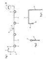
- Fig. 1 a sliced view of an inventive plate element 1 is shown.
- the Fign. 2 and 3 show an enlarged view of the designated in Fig. 1 with II and III sections.
- the plate element 1 according to the invention is made of a thin-walled material, and it has four parallel pipe receiving grooves 2 for receiving pipes through which a heating medium flows.
- tubes 3 inserted into the tube receiving grooves 2 can be seen.
- the tube receiving grooves 2 are aligned substantially along a plane, and between them are each parallel to the tube receiving grooves 2 extending reinforcing structures can be seen.
- a reinforcing rib 5 which may also be referred to as a reinforcing web, extends between the two middle tube receiving grooves 2 approximately in the center of the plate element. This is formed by a Doppelabkantung, wherein the reinforcing rib 5 is substantially perpendicular to the plane of the Tube receiving grooves 2 extends. The material is in the end region of the reinforcing rib 5 to form a loop 9 (see FIG. 2) returned by 180 °, to finally extend again in the originally intended direction.
- the plate element is bent three times at right angles, with a first, extending substantially perpendicular to the plane of the Rohrfactnuten 2 section 6, an inwardly directed, parallel to the plane of the Rohrfactnuten 2 extending section 7 and finally a parallel to section 6, again perpendicular to the plane of the tube receiving grooves 2 again towards the latter back extending end portion 8 result.
- the plate element according to the invention is resistant to bending and torsion.
- the material is bent in the end portion 8 to form a loop 10 by 180 ° and is recirculated along the portion 7, projecting into the section 6 again. This measure results in a further stiffening.
- a stiffening web 11 is shown in three different views, which can be inserted into the plate element 1 according to the invention transversely to the tubes 3.
- the stiffening web 11 has a slot-like recess 12 whose dimensions correspond to the dimensions of the reinforcing web 5.
- the stiffening web 11 has on its opposite side of the recess 12 in the outer regions recesses 13, which are arranged such that the end portions 8 engage in inserted into the plate member 1 stiffening web in these recesses.
- a tongue 14 can be seen, which is formed by bending over a material portion of the stiffening web 11. This tongue is adjacent to the recess 12 and is located in the plate element 1 used stiffening web 11th on the reinforcing rib 5 at.
- a fastening means can be guided through a hole 15 in the tongue 14 for fastening the tongue, for example a self-tapping sheet-metal screw for a plate element 1 made of a sheet steel.
- Further holes 16 in the stiffening web 11 can be used to hang the composite of the plate member 1, the tubes 3 and the stiffening web 11 radiant ceiling panel on a ceiling. For example, hooks or similar devices can be passed through these holes and connected to the ceiling.
- a further possibility for fastening the panel element according to the invention or a radiant ceiling panel constructed using this panel element 1 to a ceiling is to fix the sections 7 guided parallel to the plane of the tube receiving grooves 2 on a ceiling. This can for example also be done by means of screws or other suitable fasteners.
- the plate element according to the invention can absorb higher load capacities with the same material thickness or a reduction in the material thickness can be carried out while maintaining the same load.
- the plate element is inexpensive, preferably produced in one piece by bending.
- a steel sheet is preferable.
Landscapes
- Engineering & Computer Science (AREA)
- Mechanical Engineering (AREA)
- General Engineering & Computer Science (AREA)
- Chemical & Material Sciences (AREA)
- Combustion & Propulsion (AREA)
- Thermal Sciences (AREA)
- Sustainable Development (AREA)
- Physics & Mathematics (AREA)
- Life Sciences & Earth Sciences (AREA)
- Devices For Blowing Cold Air, Devices For Blowing Warm Air, And Means For Preventing Water Condensation In Air Conditioning Units (AREA)
- Laminated Bodies (AREA)
- Steam Or Hot-Water Central Heating Systems (AREA)
- Glass Compositions (AREA)
- Lock And Its Accessories (AREA)
- Rod-Shaped Construction Members (AREA)
- Electrochromic Elements, Electrophoresis, Or Variable Reflection Or Absorption Elements (AREA)
Description
- Die Erfindung betrifft ein Plattenelement zur Bildung einer Deckenstrahlplatte, wobei das Plattenelement aus einem dünnwandigen Material gefertigt ist und Rohraufnahmestrukturen sowie Verstärkungsstrukturen aufweist, wobei mindestens eine der Verstärkungsstrukturen als Verstärkungsrippe ausgebildet ist.
- Derartige Plattenelemente sind aus dem Stand der Technik bekannt und werden zum Aufbau von Deckenstrahlplatten, die wiederum modulartig zu einer Deckenstrahlplatten-Heizung zusammengefügt werden können, verwendet.
- Ein solches Plattenelement ist in der EP 0 961 084 A1 beschrieben. Das hier gezeigte Plattenelement ist aus einem dünnwandigen Material gefertigt und weist Rohraufnahmestrukturen in Form von Nuten auf. Zwischen benachbarten, parallel angeordneten Rohraufnahmenuten sind dabei trapezförmige Sicken zu erkennen. Diese können eine Verstärkung des gezeigten Plattenelementes bewirken.
- Bei derartigen Plattenelementen zur Bildung einer Deckenstrahlplatte ist es anzustreben, eine hohe Tragfähigkeit des Moduls bei vergleichsweise geringer Wandstärke und damit verbunden geringem Materialeinsatz zu erreichen. Hierzu sind weitere über die sickenförmigen Verstärkungsstrukturen hinaus reichende Verstärkungsmaßnahmen erforderlich.
- Ein gattungsgemäßes Plattenelement ist aus der GB 994 719 A bekannt. Das hier beschriebene Plattenelement ist aus einem dünnwandigen Material gefertigt und verfügt über Verstärkungsstrukturen in Form von Verstärkungsrippen, die stegförmig ausgebildet sind. Das Plattenelement ist einstückig durch Biegeumformung gefertigt, wobei die Verstärkungsrippen durch eine Doppelabkantung ausgebildet sind.
- Ein weiteres Plattenelement ist aus der US-A-5 042 570 bekannt. Auch das hier beschriebene Plattenelement ist aus einem dünnwandigen Material gefertigt. Zur Befestigung des Plattenelements an Wärmeaustauschelementen dienen an den Wärmeaustauschelementen angeordnete Haltemagneten. Die Wärmeaustauschelemente sind ihrerseits an einer aus Längs- und Querträgern bestehenden Trageinheit angeordnet. Dank der Anordnung der Plattenelemente an den Wärmetauschelementen mittels Magnetkraft besteht der besondere Vorteil der hier beschriebenen Lösung darin, daß zum einen eine stets flächige und gute Anlage der Plattenelemente an den Wärmetauschelementen sichergestellt ist und daß sich zum anderen die Plattenelemente in besonders einfacher Weise montieren bzw. demontieren lassen, da keine weiteren Verbindungseinrichtungen zwischen den Wärmetauschelementen einerseits und den Plattenelementen andererseits zu lösen bzw. einzurasten sind.
- Eine weitere Strahlheizflächenkonstruktion ist mit der EP-A-0 971 177 offenbart. Es ist hier eine Strahlheizflächenkonstruktion mit einer Abhängung und Strahlplatten aus Stahl- oder Aluminiumblechen beschrieben, welche zum Beispiel unter entsprechender Profilierung wenigstens einer Randaufkantung an wenigstens einem von im Abstand voneinander angeordneten Heizrohren eines Heizrohrregisters zur Wärmeübertragung auf- bzw. anliegen. Zur Verbesserung der Wirksamkeit sind die Strahlplatten von der Rückseite des Heizrohrregisters her unter Freihaltung eines vorderseitigen Abstrahlbereichs des jeweiligen Heizrohrs an bzw. auf den Heizrohren montiert.
- Es ist die Aufgabe der Erfindung, ein Plattenelement der eingangs genannten Art, wie es beispielsweise aus der GB 994 719 A bekannt ist, dahingehend weiterzuentwickeln, daß es bei gleichbleibender Materialstärke eine noch größere Festigkeit aufweist.
- Zur Lösung dieser Aufgabe wird mit der Erfindung ein Plattenelement vorgeschlagen, welches gekennzeichnet ist durch einen sich im wesentlichen quer zu den Rohraufnahmestrukturen erstreckenden, im Bereich der Verstärkungsrippe eine zu dieser korrespondierende Ausnehmung aufweisenden Aussteifungssteg.
- Eine Verstärkungsrippe zeichnet sich dadurch aus, daß sie eine verbesserte Stabilisierung bedingt. Die Verstärkungsrippe weist eine größere, sich quer zu der Richtung des zu verstärkenden Materials erstreckende Ausdehnung auf, als die herkömmlichen Verstärkungsstrukturen, beispielsweise Verstärkungssicken. Eine weitere Verstärkung des Plattenelementes erhält man, wenn, wie erfindungsgemäß vorgeschlagen, das Plattenelement mit einem quer zu den Rohraufnahmestrukturen auslaufenden Aussteifungssteg versteift ist, wobei der Aussteifungssteg mit einer zu der Verstärkungsrippe korrespondierenden Ausnehmung über die Verstärkungsrippe führbar ist. Hierbei kann an dem Aussteifungssteg im Bereich der Ausnehmung eine Zunge vorgesehen sein, die an der Verstärkungsrippe festlegbar ist. Schließlich kann der Verstärkungssteg in seinem außenseitigen Abschnitt Ausnehmungen aufweisen, in die der äußerste, dreifach umgelegte Abschnitt des Seitenbereichs des Plattenelements zur besseren Stabilisierung eingreift. Neben einer verbesserten Verstärkung dient der erfindungsgemäße Verstärkungssteg auch einem zusätzlichen Fixieren der in den Rohraufnahmestrukturen angeordneten Rohre.
- Eine besonders einfache aber dennoch effektive Verstärkungsrippe erhält man, wenn diese, wie gemäß einem Merkmal der Erfindung vorgeschlagen, stegförmig ausgebildet ist. Eine solche stegförmige Verstärkungsrippe kann beispielsweise in ein einstückig durch Biegeumformen gefertigtes Plattenelement in Form einer einfachen Doppelabkantung eingearbeitet werden. Hierzu wird das dünnwandige Material, aus dem das Plattenelement gefertigt werden soll, an der gewünschten Stelle, an der die Verstärkungsrippe angeordnet werden soll vorzugsweise zunächst um 90° umgebogen, sodann unter Ausbildung einer Materialschlaufe um 180° zurückgeführt und schließlich wieder um 90° in die ursprüngliche Richtung umgebogen.
- Damit die Verstärkungsrippe in dem Plattenelement bei montierter Deckenstrahlplatte für einen Betrachter verborgen bleibt, wird mit der Erfindung vorgeschlagen, daß die Verstärkungsrippe in Richtung der rohraufnehmenden Seite des Plattenelementes ausgebildet ist.
- Bei einem Plattenelement sind die Rohraufnahmestrukturen die in dem dünnwandigen Material für gewöhnlich in einer Ebene, parallel nebeneinander verlaufen, eingeformt. So ist das Plattenelement gegenüber Verformungen in dieser Ebene besonders empfindlich, weshalb wie gemäß einem weiteren Merkmal der Erfindung vorgeschlagen, die Verstärkungsrippe in das dünnwandige Material des Plattenelementes in etwa mittig zu den Seitenbereichen zwischen zwei Rohraufnahmestrukturen und im wesentlichen parallel dazu angeordnet wird.
- Zur zusätzlichen Stabilisierung des erfindungsgemäßen Plattenelementes wird mit der Erfindung vorgeschlagen, die Seitenbereiche des Plattenelementes dreifach in die gleiche Richtung abzukanten. Hierdurch ist eine weitere Stabilisierung des erfindungsgemäßen Plattenelementes gewährleistet. Bevorzugt wird dabei eine dreifache Abkantung um einen Winkel von jeweils etwa 90° in Richtung der rohraufnehmenden Seite des erfindungsgemäßen Plattenelementes, so daß der äußerste Abschnitt des Seitenbereichs im wesentlichen senkrecht zur Ebene der Rohraufnahmestrukturen auf diese zu gerichtet verläuft. Somit ergibt sich zum einen eine parallel zu der Ebene der Rohraufnahmestrukturen verlaufende Fläche an jeder Seite des Plattenelementes, welche beispielsweise zum Befestigen des erfindungsgemäßen Plattenelementes an einer Raumdecke genutzt werden kann. Zum anderen bietet die letzte Abkantung noch einmal eine zusätzliche Versteifung des erfindungsgemäßen Plattenelementes. Eine noch bessere Versteifung wird dadurch erreicht, daß, wie gemäß einem weiteren Merkmal der Erfindung vorgeschlagen, das dünnwandige Material des Plattenelementes in dem Seitenbereich am Ende des äußersten Abschnittes der Seitenabkantung unter Ausbildung einer Materialschlaufe umgelegt und zumindest entlang eines Teils der abgekanteten Struktur, parallel zu dieser und an dieser anliegend wieder zurückgeführt wird.
- Weitere Vorteile und Merkmale der Erfindung ergeben sich aus der nachfolgenden Beschreibung eines Ausführungsbeispiels anhand der beigefügten Figuren. Dabei zeigen:
- Fig. 1 ein erfindungsgemäßes Plattenelement mit in Rohraufnahmesicken angeordneten Rohren in geschnittener Ansicht,
- Fig. 2 in vergrößerter Darstellung den in Fig. 1 mit II bezeichneten Bereich,
- Fig. 3 in vergrößerter Darstellung den in Fig. 1 mit III bezeichneten Bereich,
- Fig. 4 eine Ansicht eines Aussteifungssteges zur weiteren Versteifung des erfindungsgemäßen Plattenelementes,
- Fig. 5 eine Ansicht von unten des in Fig. 4 gezeigten Aussteifungsstegs sowie
- Fig. 6 eine Seitenansicht des in Fig. 4 gezeigten Aussteifungsstegs.
- In Fig. 1 ist in geschnittener Ansicht ein erfindungsgemäßes Plattenelement 1 gezeigt. Die Fign. 2 sowie 3 zeigen dabei in vergrößerter Ansicht die in Fig. 1 mit II bzw. III bezeichnete Ausschnitte. Das erfindungsgemäße Plattenelement 1 ist aus einem dünnwandigen Material gefertigt, und es weist vier parallel verlaufende Rohraufnahmenuten 2 zum Aufnehmen von von einem Heizmedium durchströmten Rohren, auf. In der Fig. 1 sind in die Rohraufnahmenuten 2 eingesetzte Rohre 3 zu erkennen. Die Rohraufnahmenuten 2 sind dabei im wesentlichen entlang einer Ebene ausgerichtet, und zwischen ihnen sind jeweils sich parallel zu den Rohraufnahmenuten 2 erstreckende Verstärkungsstrukturen zu erkennen. Diese werden zum einen gebildet durch zwei sich parallel zu den Rohraufnahmenuten 2 erstreckende Verstärkungssicken 4, welche mit geringer Tiefe in das dünnwandige Material des Plattenelementes in Richtung der offenen Seite der Rohraufnahmenuten 2 eingeformt sind. Zum anderen verläuft zwischen den beiden mittleren Rohraufnahmenuten 2 in etwa mittig des Plattenelements eine erfindungsgemäße Verstärkungsrippe 5, die auch als Verstärkungssteg bezeichnet werden kann. Diese ist durch eine Doppelabkantung gebildet, wobei sich die Verstärkungsrippe 5 im wesentlichen rechtwinklig zu der Ebene der Rohraufnahmenuten 2 erstreckt. Das Material ist im Endbereich der Verstärkungsrippe 5 unter Ausbildung einer Schlaufe 9 (siehe Fig. 2) um 180° zurückgeführt, um sich schließlich wieder in der ursprünglich vorgesehenen Richtung weiter zu erstrecken.
- In den Randbereichen ist das Plattenelement dreifach rechtwinklig abgekantet, wobei sich ein erster, im wesentlichen senkrecht zu der Ebene der Rohraufnahmenuten 2 verlaufenden Abschnitt 6, ein nach innen gerichteter, parallel zur Ebene der Rohraufnahmenuten 2 verlaufende Abschnitt 7 und schließlich ein parallel zum Abschnitt 6, erneut senkrecht zu der Ebene der Rohraufnahmenuten 2 wieder in Richtung letzerer zurück verlaufender Endabschnitt 8 ergeben.
- Sowohl die Verstärkungsrippe 5 als auch die in den Abschnitten 6, 7 und 8 ausgeführte dreifache Abkantung der Seitenbereiche des erfindungsgemäßen Plattenelementes bilden eine deutlich verbesserte Verstärkung des Elementes. So ist das erfindungsgemäße Plattenelement verbiegungs- und torsionssteifer. Für eine weiter verbesserte Versteifung ist, wie in Fig. 3 gezeigt, das Material in dem Endabschnitt 8 unter Ausbildung einer Schlaufe 10 um 180° umgebogen und wird entlang dem Abschnitt 7, bis in den Abschnitt 6 hineinragend wieder zurückgeführt. Diese Maßnahme ergibt eine noch weitergehende Versteifung.
- In den Fign. 4 bis 6 ist in drei verschiedenen Ansichten ein Aussteifungssteg 11 gezeigt, der in das erfindungsgemäße Plattenelement 1 quer zu den Rohren 3 einsetzbar ist. Der Aussteifungssteg 11 weist eine schlitzartige Ausnehmung 12 auf, deren Abmessungen mit den Maßen des Verstärkungssteges 5 korrespondieren. Der Aussteifungssteg 11 weist an seiner der Ausnehmung 12 gegenüberliegenden Seite jeweils in den Außenbereichen Ausnehmungen 13 auf, welche derart angeordnet sind, daß die Endabschnitte 8 bei in das Plattenelement 1 eingesetztem Aussteifungssteg in diese Ausnehmungen eingreifen. Dadurch wird neben einer Befestigung des Aussteifungssteges 11 eine weitere Stabilisierung des so verstärkten Plattenelementes erreicht. In den Fign. 5 sowie 6 ist eine Zunge 14 zu erkennen, die durch Umbiegen eines Materialabschnittes des Aussteifungssteges 11 gebildet ist. Diese Zunge ist der Ausnehmung 12 benachbart und liegt bei in das Plattenelement 1 eingesetzte Aussteifungssteg 11 an der Verstärkungsrippe 5 an. Durch ein Loch 15 in der Zunge 14 kann zum Befestigen der Zunge ein Befestigungsmittel geführt werden, für ein aus einem Stahlblech gefertigtes Plattenelement 1 beispielsweise eine selbstschneidende Blechschraube. Weitere Löcher 16 in dem Aussteifungssteg 11 können dabei zum Aufhängen der aus dem Plattenelement 1, den Rohren 3 sowie dem Aussteifungssteg 11 zusammengesetzten Deckenstrahlplatte an einer Raumdecke genutzt werden. So können beispielsweise Haken oder ähnliche Vorrichtungen durch diese Löcher geführt und mit der Raumdecke verbunden werden.
- Eine weitere Möglichkeit, das erfindungsgemäße Plattenelement bzw. eine unter Verwendung dieses Plattenelementes 1 aufgebaute Deckenstrahlplatte an einer Raumdecke zu befestigen liegt darin, die parallel zur Ebene der Rohraufnahmenuten 2 geführten Abschnitte 7 an einer Raumdecke festzulegen. Dies kann beispielsweise ebenfalls mittels Schrauben oder anderen, geeigneten Befestigungsmitteln geschehen.
- Das erfindungsgemäße Plattenelement kann aufgrund seiner verbesserten Verstärkung bei gleicher Materialstärke höhere Traglasten aufnehmen bzw. es kann bei gleichbleibender Traglast eine Verringerung der Materialstärke erfolgen. Das Plattenelement ist kostengünstig, vorzugsweise einstückig durch Biegeumformen herstellbar.
- Als Ausgangsmaterial zur Herstellung des Plattenelements wird ein Stahlblech bevorzugt.
-
- 1
- Plattenelement
- 2
- Rohraufnahmenuten
- 3
- Rohr
- 4
- Verstärkungssicke
- 5
- Verstärkungsrippe
- 5
- Abschnitt
- 7
- Abschnitt
- 8
- Abschnitt
- 9
- Schlaufe
- 10
- Schlaufe
- 11
- Aussteifungssteg
- 12
- Ausnehmung
- 13
- Ausnehmung
- 14
- Zunge
- 15
- Loch
- 16
- Loch
Claims (10)
- Plattenelement zur Bildung einer Deckenstrahlplatte, wobei das Plattenelement (1) aus einem dünnwandigen Material gefertigt ist und Rohraufnahmestrukturen (2) sowie Verstärkungsstrukturen (4, 5) aufweist, wobei mindestens eine der Verstärkungsstrukturen (4, 5) als Verstärkungsrippe (5) ausgebildet ist, gekennzeichnet durch einen sich im wesentlichen quer zu den Rohraufnahmestrukturen (2) erstreckenden, im Bereich der Verstärkungsrippe (5) eine zu dieser korrespondierende Ausnehmung (12) aufweisenden Aussteifungssteg (11).
- Plattenelement nach Anspruch 1, dadurch gekennzeichnet, daß der Aussteifungssteg (11) im Bereich der zu der Verstärkungsrippe (5) korrespondierenden Ausnehmung (12) eine Zunge (14) aufweist, mit der er an der Verstärkungsrippe (5) festlegbar ist.
- Plattenelement nach einem der Ansprüche 1 oder 2, dadurch gekennzeichnet, daß der Aussteifungssteg (11) an seiner zu der Verstärkungsrippe (5) korrespondierenden Ausnehmung (12) gegenüberliegenden Seite in den äußeren Abschnitten weitere Ausnehmungen (13) aufweist, in denen die äußersten Abschnitte (8) der Seitenbereiche des Plattenelementes (1) festlegbar sind.
- Plattenelement nach einem der vorhergehenden Ansprüche, gekennzeichnet durch eine stegförmige Verstärkungsrippe (5).
- Plattenelement nach einem der vorhergehenden Ansprüche, dadurch gekennzeichnet, daß es einstückig durch Biegeumformen gefertigt ist, wobei die mindestens eine Verstärkungsrippe (5) durch eine Doppelabkantung gebildet ist.
- Plattenelement nach einem der voranstehenden Ansprüche, dadurch gekennzeichnet, daß die Verstärkungsrippe (5) in Richtung der rohraufnehmenden Seite des Plattenelementes ausgebildet ist.
- Plattenelement nach einem der voranstehenden Ansprüche, dadurch gekennzeichnet, daß die mindestens eine Verstärkungsrippe (5) sich zwischen zwei im wesentlichen parallel verlaufenden, in einer Ebene liegenden Rohraufnahmestrukturen (2) im wesentlichen parallel zu diesen erstreckt, wobei die Verstärkungsrippe (5) im wesentlichen mittig zwischen den Seitenbereichen des Plattenelementes (1) angeordnet ist.
- Plattenelement nach einem der voranstehenden Ansprüche, dadurch gekennzeichnet, daß es in seinen Seitenbereichen jeweils eine dreifache Abkantung aufweist, wobei die Abkantungen jeweils in Richtung derselben Oberfläche des dünnwandigen Materials verlaufen.
- Plattenelement nach Anspruch 8, dadurch gekennzeichnet, daß es in seinen Seitenbereichen drei Abkantungen um jeweils etwa 90° aufweist, wobei der äußerste Abschnitt (8) des Plattenelementes im wesentlichen senkrecht zu der Ebene der Rohraufnahmestrukturen (2) auf diese zu gerichtet verläuft.
- Plattenelement nach einem der Ansprüche 8 oder 9, dadurch gekennzeichnet, daß am Ende des äußersten Abschnittes (8) das dünnwandige Material um einen Winkel von 180° umgelenkt zurückgeführt ist.
Applications Claiming Priority (2)
| Application Number | Priority Date | Filing Date | Title |
|---|---|---|---|
| DE20111852U | 2001-07-17 | ||
| DE20111852U DE20111852U1 (de) | 2001-07-17 | 2001-07-17 | Plattenelement |
Publications (3)
| Publication Number | Publication Date |
|---|---|
| EP1278019A2 EP1278019A2 (de) | 2003-01-22 |
| EP1278019A3 EP1278019A3 (de) | 2004-06-23 |
| EP1278019B1 true EP1278019B1 (de) | 2006-12-27 |
Family
ID=7959411
Family Applications (1)
| Application Number | Title | Priority Date | Filing Date |
|---|---|---|---|
| EP02015145A Expired - Lifetime EP1278019B1 (de) | 2001-07-17 | 2002-07-06 | Plattenelement |
Country Status (4)
| Country | Link |
|---|---|
| EP (1) | EP1278019B1 (de) |
| AT (1) | ATE349657T1 (de) |
| DE (2) | DE20111852U1 (de) |
| DK (1) | DK1278019T3 (de) |
Families Citing this family (8)
| Publication number | Priority date | Publication date | Assignee | Title |
|---|---|---|---|---|
| CH698137B1 (de) * | 2004-12-01 | 2009-05-29 | Markus Amann | Heiz- oder Kühlelement. |
| DE102004062630A1 (de) * | 2004-12-24 | 2006-07-06 | Volkswagen Ag | Einschaliges Bauteil |
| ITTV20060079A1 (it) * | 2006-05-17 | 2007-11-18 | Termotecniche Fraccaro O T F S | Procedimento per la realizzazione di pannelli radianti. |
| SI2006608T1 (sl) * | 2007-06-18 | 2021-12-31 | Klima-Top Gmbh | Stenske ali stropne obloge |
| DE202009003205U1 (de) | 2009-03-05 | 2009-08-06 | Zehnder Verkaufs- Und Verwaltungs Ag | Plattenelement für ein Deckenheizungs- und/oder Kühlungselement |
| AT512943B1 (de) | 2012-04-19 | 2013-12-15 | Robert Peer | Wärmeleitprofil |
| DE102015003279B4 (de) * | 2015-03-16 | 2024-04-04 | Schmöle GmbH | Flächenwärmetauscher und Verfahren zu dessen Herstellung |
| EP3803221B1 (de) * | 2018-05-24 | 2023-07-05 | Zehnder Group International AG | Decken-temperierkörper |
Family Cites Families (7)
| Publication number | Priority date | Publication date | Assignee | Title |
|---|---|---|---|---|
| DE1021995B (de) * | 1955-03-23 | 1958-01-02 | Meyer Fa Rud Otto | Strahlungsheizflaeche aus Blechplatten |
| GB994719A (en) * | 1963-03-25 | 1965-06-10 | G N Haden & Sons Ltd | Improvements in heated or cooled ceiling or wall structures |
| DE3266655D1 (en) | 1982-06-04 | 1985-11-07 | Hell Rudolf Dr Ing Gmbh | Process to avoid image defects in multicolour printing caused by non coincident printing of the colour separations |
| DE3921719A1 (de) * | 1989-07-01 | 1991-01-10 | Wilhelmi Werke Gmbh & Co Kg | Deckenverkleidung |
| EP0733865B1 (de) * | 1995-03-21 | 2002-07-24 | GIACOMINI S.p.A. | Konstruktion einer Heiz- und/oder Kühldecke |
| DE19830245A1 (de) * | 1998-07-07 | 2000-01-13 | Menge Klaus | Strahlheizflächenkonstruktion |
| DE20002868U1 (de) * | 2000-02-17 | 2000-05-04 | Frenger Systemen BV Heiz- und Kühltechnik GmbH, 64823 Groß-Umstadt | Strahlflächenaufbau |
-
2001
- 2001-07-17 DE DE20111852U patent/DE20111852U1/de not_active Expired - Lifetime
-
2002
- 2002-07-06 AT AT02015145T patent/ATE349657T1/de active
- 2002-07-06 DE DE50209056T patent/DE50209056D1/de not_active Expired - Lifetime
- 2002-07-06 EP EP02015145A patent/EP1278019B1/de not_active Expired - Lifetime
- 2002-07-06 DK DK02015145T patent/DK1278019T3/da active
Also Published As
| Publication number | Publication date |
|---|---|
| DE20111852U1 (de) | 2001-09-20 |
| EP1278019A2 (de) | 2003-01-22 |
| EP1278019A3 (de) | 2004-06-23 |
| DE50209056D1 (de) | 2007-02-08 |
| ATE349657T1 (de) | 2007-01-15 |
| DK1278019T3 (da) | 2007-05-07 |
Similar Documents
| Publication | Publication Date | Title |
|---|---|---|
| DE69309699T3 (de) | Sicherheitsbalken | |
| DE69711573T2 (de) | Stütze für Trägerkanäle | |
| EP1201940B1 (de) | Schienenmutterprofil | |
| DE69311713T2 (de) | Gerippte platte für eine verbundplatte | |
| WO2010149625A1 (de) | Haltewinkel für ein fassadensystem | |
| EP0735209B1 (de) | Längs- oder Querträger für eine Deckenverkleidung | |
| EP0070532B1 (de) | Schalldämmendes Wandbausystem für Industriebauten, sowie Kassettenprofil hierfür | |
| DE3879497T2 (de) | Metallstuetze. | |
| EP1278019A2 (de) | Plattenelement | |
| DE102017101509A1 (de) | Konsole zur Befestigung von Fassadenelementen | |
| DE3729824C2 (de) | ||
| EP3938713B1 (de) | Modulares system, strahlplattenmodul und verfahren | |
| EP0647747A1 (de) | Tragwerk für die Bedachung und/oder Aussenhaut-Beplankung von Gebäuden | |
| DE19526207A1 (de) | Stahltürblatt | |
| DE212004000081U1 (de) | Halteanordnung zum Halten eines Blaublechs | |
| DE29901412U1 (de) | Lochrasterplatte, insbesondere für Textilien-Transportfahrzeuge, Container, Behälter und Aufbauten jeglicher Art | |
| EP1279356A1 (de) | Fachboden für ein Regal sowie Regal | |
| DE19950890C1 (de) | Ständerprofilstab zur Errichtung von Trockenbauwänden | |
| EP4145651B1 (de) | Endseitig einseitig abgestützter ausleger für ein kabeltragsystem | |
| DE2610978C2 (de) | Ofenauskleidung | |
| DE102022125081B3 (de) | Bodenstütze eines Kabeltragsystems | |
| DE102021120323B4 (de) | Endseitig einseitig abgestützter Ausleger für ein Kabeltragsystem | |
| EP0524337B1 (de) | Doppelschaliges Aussenwandsystem | |
| DE3233562C1 (de) | Rohrverbolzung für Streckenausbauprofile | |
| DE10046918B4 (de) | Gleitlager für Schiebeböden |
Legal Events
| Date | Code | Title | Description |
|---|---|---|---|
| PUAI | Public reference made under article 153(3) epc to a published international application that has entered the european phase |
Free format text: ORIGINAL CODE: 0009012 |
|
| AK | Designated contracting states |
Kind code of ref document: A2 Designated state(s): AT BE BG CH CY CZ DE DK EE ES FI FR GB GR IE IT LI LU MC NL PT SE SK TR |
|
| AX | Request for extension of the european patent |
Free format text: AL;LT;LV;MK;RO;SI |
|
| PUAL | Search report despatched |
Free format text: ORIGINAL CODE: 0009013 |
|
| AK | Designated contracting states |
Kind code of ref document: A3 Designated state(s): AT BE BG CH CY CZ DE DK EE ES FI FR GB GR IE IT LI LU MC NL PT SE SK TR |
|
| AX | Request for extension of the european patent |
Extension state: AL LT LV MK RO SI |
|
| 17P | Request for examination filed |
Effective date: 20040727 |
|
| AKX | Designation fees paid |
Designated state(s): AT BE BG CH CY CZ DE DK EE ES FI FR GB GR IE IT LI LU MC NL PT SE SK TR |
|
| GRAP | Despatch of communication of intention to grant a patent |
Free format text: ORIGINAL CODE: EPIDOSNIGR1 |
|
| GRAS | Grant fee paid |
Free format text: ORIGINAL CODE: EPIDOSNIGR3 |
|
| GRAA | (expected) grant |
Free format text: ORIGINAL CODE: 0009210 |
|
| AK | Designated contracting states |
Kind code of ref document: B1 Designated state(s): AT BE BG CH CY CZ DE DK EE ES FI FR GB GR IE IT LI LU MC NL PT SE SK TR |
|
| PG25 | Lapsed in a contracting state [announced via postgrant information from national office to epo] |
Ref country code: SK Free format text: LAPSE BECAUSE OF FAILURE TO SUBMIT A TRANSLATION OF THE DESCRIPTION OR TO PAY THE FEE WITHIN THE PRESCRIBED TIME-LIMIT Effective date: 20061227 Ref country code: IE Free format text: LAPSE BECAUSE OF FAILURE TO SUBMIT A TRANSLATION OF THE DESCRIPTION OR TO PAY THE FEE WITHIN THE PRESCRIBED TIME-LIMIT Effective date: 20061227 Ref country code: CZ Free format text: LAPSE BECAUSE OF FAILURE TO SUBMIT A TRANSLATION OF THE DESCRIPTION OR TO PAY THE FEE WITHIN THE PRESCRIBED TIME-LIMIT Effective date: 20061227 |
|
| REG | Reference to a national code |
Ref country code: GB Ref legal event code: FG4D Free format text: NOT ENGLISH |
|
| REG | Reference to a national code |
Ref country code: IE Ref legal event code: FG4D Free format text: LANGUAGE OF EP DOCUMENT: GERMAN |
|
| REF | Corresponds to: |
Ref document number: 50209056 Country of ref document: DE Date of ref document: 20070208 Kind code of ref document: P |
|
| REG | Reference to a national code |
Ref country code: CH Ref legal event code: NV Representative=s name: E. BLUM & CO. AG PATENT- UND MARKENANWAELTE VSP |
|
| REG | Reference to a national code |
Ref country code: SE Ref legal event code: TRGR |
|
| GBT | Gb: translation of ep patent filed (gb section 77(6)(a)/1977) |
Effective date: 20070226 |
|
| PG25 | Lapsed in a contracting state [announced via postgrant information from national office to epo] |
Ref country code: BG Free format text: LAPSE BECAUSE OF FAILURE TO SUBMIT A TRANSLATION OF THE DESCRIPTION OR TO PAY THE FEE WITHIN THE PRESCRIBED TIME-LIMIT Effective date: 20070327 |
|
| PG25 | Lapsed in a contracting state [announced via postgrant information from national office to epo] |
Ref country code: ES Free format text: LAPSE BECAUSE OF FAILURE TO SUBMIT A TRANSLATION OF THE DESCRIPTION OR TO PAY THE FEE WITHIN THE PRESCRIBED TIME-LIMIT Effective date: 20070407 |
|
| REG | Reference to a national code |
Ref country code: DK Ref legal event code: T3 |
|
| PG25 | Lapsed in a contracting state [announced via postgrant information from national office to epo] |
Ref country code: PT Free format text: LAPSE BECAUSE OF FAILURE TO SUBMIT A TRANSLATION OF THE DESCRIPTION OR TO PAY THE FEE WITHIN THE PRESCRIBED TIME-LIMIT Effective date: 20070528 |
|
| ET | Fr: translation filed | ||
| PLBE | No opposition filed within time limit |
Free format text: ORIGINAL CODE: 0009261 |
|
| STAA | Information on the status of an ep patent application or granted ep patent |
Free format text: STATUS: NO OPPOSITION FILED WITHIN TIME LIMIT |
|
| 26N | No opposition filed |
Effective date: 20070928 |
|
| PG25 | Lapsed in a contracting state [announced via postgrant information from national office to epo] |
Ref country code: MC Free format text: LAPSE BECAUSE OF NON-PAYMENT OF DUE FEES Effective date: 20070731 Ref country code: GR Free format text: LAPSE BECAUSE OF FAILURE TO SUBMIT A TRANSLATION OF THE DESCRIPTION OR TO PAY THE FEE WITHIN THE PRESCRIBED TIME-LIMIT Effective date: 20070328 |
|
| PG25 | Lapsed in a contracting state [announced via postgrant information from national office to epo] |
Ref country code: EE Free format text: LAPSE BECAUSE OF FAILURE TO SUBMIT A TRANSLATION OF THE DESCRIPTION OR TO PAY THE FEE WITHIN THE PRESCRIBED TIME-LIMIT Effective date: 20061227 |
|
| PG25 | Lapsed in a contracting state [announced via postgrant information from national office to epo] |
Ref country code: CY Free format text: LAPSE BECAUSE OF FAILURE TO SUBMIT A TRANSLATION OF THE DESCRIPTION OR TO PAY THE FEE WITHIN THE PRESCRIBED TIME-LIMIT Effective date: 20061227 |
|
| PG25 | Lapsed in a contracting state [announced via postgrant information from national office to epo] |
Ref country code: TR Free format text: LAPSE BECAUSE OF FAILURE TO SUBMIT A TRANSLATION OF THE DESCRIPTION OR TO PAY THE FEE WITHIN THE PRESCRIBED TIME-LIMIT Effective date: 20061227 |
|
| PGFP | Annual fee paid to national office [announced via postgrant information from national office to epo] |
Ref country code: LU Payment date: 20130722 Year of fee payment: 12 |
|
| PG25 | Lapsed in a contracting state [announced via postgrant information from national office to epo] |
Ref country code: LU Free format text: LAPSE BECAUSE OF NON-PAYMENT OF DUE FEES Effective date: 20140706 |
|
| REG | Reference to a national code |
Ref country code: FR Ref legal event code: PLFP Year of fee payment: 15 |
|
| REG | Reference to a national code |
Ref country code: CH Ref legal event code: PFUS Owner name: ZEHNDER GROUP INTERNATIONAL AG, CH Free format text: FORMER OWNER: ZEHNDER VERKAUFS- UND VERWALTUNGS AG, CH |
|
| REG | Reference to a national code |
Ref country code: FR Ref legal event code: PLFP Year of fee payment: 16 |
|
| REG | Reference to a national code |
Ref country code: NL Ref legal event code: PD Owner name: ZEHNDER GROUP INTERNATIONAL AG; CH Free format text: DETAILS ASSIGNMENT: CHANGE OF OWNER(S), MERGE; FORMER OWNER NAME: ZEHNDER VERKAUFS- UND VERWALTUNGS AG Effective date: 20170517 |
|
| REG | Reference to a national code |
Ref country code: GB Ref legal event code: 732E Free format text: REGISTERED BETWEEN 20170817 AND 20170823 |
|
| REG | Reference to a national code |
Ref country code: DE Ref legal event code: R082 Ref document number: 50209056 Country of ref document: DE Representative=s name: BRINKMANN & PARTNER PATENTANWAELTE PARTNERSCHA, DE Ref country code: DE Ref legal event code: R082 Ref document number: 50209056 Country of ref document: DE Representative=s name: RAUSCH WANISCHECK-BERGMANN BRINKMANN PARTNERSC, DE Ref country code: DE Ref legal event code: R082 Ref document number: 50209056 Country of ref document: DE Representative=s name: STENGER WATZKE RING INTELLECTUAL PROPERTY, DE Ref country code: DE Ref legal event code: R081 Ref document number: 50209056 Country of ref document: DE Owner name: ZEHNDER GROUP INTERNATIONAL AG, CH Free format text: FORMER OWNER: ZEHNDER VERKAUFS- UND VERWALTUNGS-AG, GRAENICHEN, CH |
|
| REG | Reference to a national code |
Ref country code: FR Ref legal event code: TP Owner name: ZEHNDER GROUP INTERNATIONAL AG, CH Effective date: 20171009 |
|
| REG | Reference to a national code |
Ref country code: AT Ref legal event code: PC Ref document number: 349657 Country of ref document: AT Kind code of ref document: T Owner name: ZEHNDER GROUP INTERNATIONAL AG, CH Effective date: 20171213 |
|
| REG | Reference to a national code |
Ref country code: DE Ref legal event code: R082 Ref document number: 50209056 Country of ref document: DE Representative=s name: BRINKMANN & PARTNER PATENTANWAELTE PARTNERSCHA, DE Ref country code: DE Ref legal event code: R082 Ref document number: 50209056 Country of ref document: DE Representative=s name: RAUSCH WANISCHECK-BERGMANN BRINKMANN PARTNERSC, DE |
|
| REG | Reference to a national code |
Ref country code: FR Ref legal event code: PLFP Year of fee payment: 17 |
|
| PGFP | Annual fee paid to national office [announced via postgrant information from national office to epo] |
Ref country code: NL Payment date: 20210721 Year of fee payment: 20 |
|
| PGFP | Annual fee paid to national office [announced via postgrant information from national office to epo] |
Ref country code: IT Payment date: 20210727 Year of fee payment: 20 Ref country code: FI Payment date: 20210722 Year of fee payment: 20 Ref country code: FR Payment date: 20210727 Year of fee payment: 20 Ref country code: AT Payment date: 20210722 Year of fee payment: 20 |
|
| PGFP | Annual fee paid to national office [announced via postgrant information from national office to epo] |
Ref country code: DK Payment date: 20210723 Year of fee payment: 20 Ref country code: GB Payment date: 20210721 Year of fee payment: 20 Ref country code: SE Payment date: 20210721 Year of fee payment: 20 Ref country code: DE Payment date: 20210721 Year of fee payment: 20 Ref country code: CH Payment date: 20210721 Year of fee payment: 20 Ref country code: BE Payment date: 20210721 Year of fee payment: 20 |
|
| REG | Reference to a national code |
Ref country code: DE Ref legal event code: R071 Ref document number: 50209056 Country of ref document: DE Ref country code: NL Ref legal event code: MK Effective date: 20220705 |
|
| REG | Reference to a national code |
Ref country code: DK Ref legal event code: EUP Expiry date: 20220706 |
|
| REG | Reference to a national code |
Ref country code: CH Ref legal event code: PL |
|
| REG | Reference to a national code |
Ref country code: GB Ref legal event code: PE20 Expiry date: 20220705 |
|
| REG | Reference to a national code |
Ref country code: BE Ref legal event code: MK Effective date: 20220706 |
|
| REG | Reference to a national code |
Ref country code: FI Ref legal event code: MAE |
|
| REG | Reference to a national code |
Ref country code: AT Ref legal event code: MK07 Ref document number: 349657 Country of ref document: AT Kind code of ref document: T Effective date: 20220706 |
|
| REG | Reference to a national code |
Ref country code: SE Ref legal event code: EUG |
|
| PG25 | Lapsed in a contracting state [announced via postgrant information from national office to epo] |
Ref country code: GB Free format text: LAPSE BECAUSE OF EXPIRATION OF PROTECTION Effective date: 20220705 |