EP1277521A2 - Beschichtungsanlage mit einem Abdeckband für eine Gehäuseöffnung - Google Patents
Beschichtungsanlage mit einem Abdeckband für eine Gehäuseöffnung Download PDFInfo
- Publication number
- EP1277521A2 EP1277521A2 EP02015530A EP02015530A EP1277521A2 EP 1277521 A2 EP1277521 A2 EP 1277521A2 EP 02015530 A EP02015530 A EP 02015530A EP 02015530 A EP02015530 A EP 02015530A EP 1277521 A2 EP1277521 A2 EP 1277521A2
- Authority
- EP
- European Patent Office
- Prior art keywords
- carriage
- housing
- coating
- cover
- cover strip
- Prior art date
- Legal status (The legal status is an assumption and is not a legal conclusion. Google has not performed a legal analysis and makes no representation as to the accuracy of the status listed.)
- Granted
Links
Images

Classifications
-
- B—PERFORMING OPERATIONS; TRANSPORTING
- B05—SPRAYING OR ATOMISING IN GENERAL; APPLYING FLUENT MATERIALS TO SURFACES, IN GENERAL
- B05B—SPRAYING APPARATUS; ATOMISING APPARATUS; NOZZLES
- B05B13/00—Machines or plants for applying liquids or other fluent materials to surfaces of objects or other work by spraying, not covered by groups B05B1/00 - B05B11/00
- B05B13/02—Means for supporting work; Arrangement or mounting of spray heads; Adaptation or arrangement of means for feeding work
- B05B13/04—Means for supporting work; Arrangement or mounting of spray heads; Adaptation or arrangement of means for feeding work the spray heads being moved during spraying operation
-
- B—PERFORMING OPERATIONS; TRANSPORTING
- B05—SPRAYING OR ATOMISING IN GENERAL; APPLYING FLUENT MATERIALS TO SURFACES, IN GENERAL
- B05B—SPRAYING APPARATUS; ATOMISING APPARATUS; NOZZLES
- B05B13/00—Machines or plants for applying liquids or other fluent materials to surfaces of objects or other work by spraying, not covered by groups B05B1/00 - B05B11/00
- B05B13/02—Means for supporting work; Arrangement or mounting of spray heads; Adaptation or arrangement of means for feeding work
- B05B13/04—Means for supporting work; Arrangement or mounting of spray heads; Adaptation or arrangement of means for feeding work the spray heads being moved during spraying operation
- B05B13/0431—Means for supporting work; Arrangement or mounting of spray heads; Adaptation or arrangement of means for feeding work the spray heads being moved during spraying operation with spray heads moved by robots or articulated arms, e.g. for applying liquid or other fluent material to three-dimensional [3D] surfaces
- B05B13/0433—Means for supporting work; Arrangement or mounting of spray heads; Adaptation or arrangement of means for feeding work the spray heads being moved during spraying operation with spray heads moved by robots or articulated arms, e.g. for applying liquid or other fluent material to three-dimensional [3D] surfaces the work being vehicle components, e.g. vehicle bodies
-
- B—PERFORMING OPERATIONS; TRANSPORTING
- B05—SPRAYING OR ATOMISING IN GENERAL; APPLYING FLUENT MATERIALS TO SURFACES, IN GENERAL
- B05B—SPRAYING APPARATUS; ATOMISING APPARATUS; NOZZLES
- B05B13/00—Machines or plants for applying liquids or other fluent materials to surfaces of objects or other work by spraying, not covered by groups B05B1/00 - B05B11/00
- B05B13/02—Means for supporting work; Arrangement or mounting of spray heads; Adaptation or arrangement of means for feeding work
- B05B13/04—Means for supporting work; Arrangement or mounting of spray heads; Adaptation or arrangement of means for feeding work the spray heads being moved during spraying operation
- B05B13/0447—Installation or apparatus for applying liquid or other fluent material to conveyed separate articles
- B05B13/0452—Installation or apparatus for applying liquid or other fluent material to conveyed separate articles the objects being vehicle components, e.g. vehicle bodies
Definitions
- the invention relates to a coating system according to the preamble Claim 1.
- it is the Series coating of vehicle bodies and other workpieces with linear z. B. movable parallel to the workpiece conveying direction Robots, although the invention i.a. also for those at the Vehicle painting also usual roof and side machines is applicable.
- the atomizers are arranged on linearly movable carriages, in a slot-like opening of a housing the coating machine out and to the housing interior facing sides with leading inside the housing supply lines connected to the atomizer, the housing opening to protect the interior against the environment with a covered with the slide moving band is covered (WO 95/09697).
- a particular problem also arises when two or more variable pitch carriages should be present.
- a typical example of this is a coating system with on a common rail construction movable robots whose mutual distance constantly changing during operation, so that the known Bandabdeckkonstrutationen can not be used. In such coating systems, therefore, you had to be so far to settle for the housing openings with an air curtain cover.
- the invention is therefore based on the object, a coating system indicate the disadvantages mentioned above be avoided and the housing opening in a simple way then it can be covered if several carriages with variable mutual distance are available.
- the stationary masking tape makes it possible to have as many as you like To arrange sled on a rail construction and yet a simultaneous cover of the housing opening by a common Masking tape to reach, without being affected by respective supply lines on each carriage.
- the invention can be realized with simple means.
- the masking tape need hardly be longer than the housing opening to be covered.
- a Bandlhackung can be compensated by simple means.
- the complicated mechanisms for guidance and diversion omitted the known moving masking tapes.
- the cover strip can be fastened with its ends to the housing, but the sealing effect of the cover tape is improved when the coating system a clamping device for clamping the Covering tape has.
- the masking tape can be outside the lifted off of the lifting device Area inside the housing abut the opening.
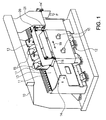
- Fig. 1 shows a housing 10 of a coating system.
- Housing 10 is a rail 11, on which a carriage 12 in a slot-like housing opening, not shown here is guided parallel to the workpiece conveying direction.
- Carriage 12 is along the housing opening in the directions the double arrow 19 movable.
- On the carriage 12 can a also not shown, with the carriage 12 movable Painting robot be attached.
- a cover strip 13 closes the housing opening and thus protects the arranged in the housing 10 Components against contamination by coating material or from other components damaging external influences.
- the cover strip 13 is z at its two ends.
- B. by means Fastening devices 14, 14 'attached to the housing, ie in arranged stationary in its longitudinal direction.
- the band 13 may, for. B. at one end in the by a deflection formed fastening device 14 'via a indicated by the arrow F, the expert known tensioning device be taut to ensure optimum sealing of the Enclosure interior to ensure the environment.
- utilities 15 for the robot are through the sled 12 and under the raised by pulleys 16 and 17 masking tape 13 passed.
- On the rail 11 can more Sled with other robots can be arranged.
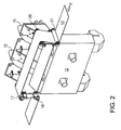
- Fig. 2 shows the carriage 12 in detail and the course of the cover strip 13.
- the masking tape is over the lower pulley 16 led upwards and thus lifted from the housing opening.
- the lower pulley is parallel to the axis with its axis Level of the opening to be covered transverse to its longitudinal direction so arranged that its lower edge facing the opening in or near the plane of the opening.
- the tape is then the Course of the housing opening following on a second, in the from the enclosure interior facing direction of the plane of the plane spaced band plane parallel to the longitudinal direction continued until finally through a second upper guide roller 20 and a second lower guide roller 21 again is attributed to the original band level.
- Fig. 3 shows a design possibility for the coating system in the area considered here with a housing 31, one on a rail construction 36 within the housing 31 movable carriage 32, a cover 33, lower Pulleys 34 and upper pulleys 35.
- the band 33rd serves to cover the recognizable at 38 slot-like housing opening, through the supply lines 37 e.g. for one Robots are performed. Below that of the lower pulleys each lifted portion of the cover 33, the Supply lines 37 the carriage 32 from the interior of the Housing 31 tracked. The supply lines become So through the gap between the lower and upper pulleys led into the sled.
- the masking tape seals 33 the housing opening 38 in front of and behind the carriage opposite From the environment, the tape on both sides tight the opening 38 bounding surfaces of a stationary panel 39 rests.
- the stationary masking tape can with its transverse direction both arranged horizontally as well as vertically or in any inclined positions be, and also the longitudinal direction of the covered by him Slot can be any horizontal, vertical or oblique run.
- the invention also for the cover curved slots, so in non-linear movement of the sled.
Landscapes
- Details Or Accessories Of Spraying Plant Or Apparatus (AREA)
- Spray Control Apparatus (AREA)
- Coating Apparatus (AREA)
- Manipulator (AREA)
- Road Paving Machines (AREA)
- Conveying And Assembling Of Building Elements In Situ (AREA)
Abstract
Description
- Fig. 1
- eine schematisch vereinfachte perspektivische Ansicht eines Gehäuseauschnitts einer Ausführungsform der Beschichtungsanlage;
- Fig. 2
- eine perspektivische Detailansicht eines Schlittens aus Fig. 1; und
- Fig. 3
- einen Querschnitt durch das Gehäuse und den Schlitten einer praktisch realisierten Ausführungsform der Beschichtungsanlage.
Claims (7)
- Beschichtungsanlage zur Beschichtung von Werkstücken
mit mindestens einer Maschine, die mindestens einen längs einer Schienenkonstruktion (11, 36) entlang einer schlitzartigen Öffnung (38) eines Gehäuses (10, 31) verfahrbaren Schlitten (12, 32) aufweist,
und mit einem Abdeckband (13,33), das die Gehäuseöffnung während der Verfahrbewegung des Schlittens (12, 32) in Verfahrrichtung vor und hinter diesem gegenüber der Umgebung abdeckt,
dadurch gekennzeichnet, dass das Abdeckband (13, 33) während der Schlittenbewegung stationär angeordnet ist,
und dass der Schlitten (12, 32) eine Abhebeeinrichtung (16, 17, 20, 21, 34, 35) aufweist, die das Abdeckband (13, 33) von der abzudeckenden Gehäuseöffnung (38) abhebt. - Beschichtungsanlage nach Anspruch 1, dadurch gekennzeichnet, dass die Abhebeeinrichtung quer zu der Ebene der abzudeckenden Gehäuseöffnung (38) beabstandete Umlenkrollen (16, 17, 20, 21, 34, 35) und/oder Umlenkflächen für das Abdeckband (13, 33) aufweist.
- Beschichtungsanlage nach Anspruch 1 oder 2, dadurch gekennzeichnet, dass das Abdeckband (13, 33) mit seinen Enden am Gehäuse (10, 31) befestigt ist.
- Beschichtungsanlage nach einem der vorhergehenden Ansprüche, dadurch gekennzeichnet, dass das eine Ende des Abdeckbandes (13, 33) an einer Spanneinrichtung zum Spannen des Abdeckbandes (13, 33) befestigt ist.
- Beschichtungsanlage nach einem der vorhergehenden Ansprüche, dadurch gekennzeichnet, dass der Schlitten (12, 32) mit durch die Gehäuseöffnung (38) hindurchgeführten Versorgungsleitungen (15, 37) für eine von dem Schlitten bewegbare Beschichtungs- oder sonstige Vorrichtung der Anlage verbunden ist, die durch die unter dem abgehobenen Abdeckband (13, 33) gebildete Lücke in den Schlitten geführt sind.
- Beschichtungsanlage nach einem der vorhergehenden Ansprüche, dadurch gekennzeichnet, dass das Abdeckband (13, 33) außerhalb des von der Abhebeeinrichtung (16, 17, 20, 21, 34, 35) abgehobenen Bereichs an der Gehäuseöffnung (38) anliegt.
- Beschichtungsanlage nach einem der vorhergehenden Ansprüche, dadurch gekennzeichnet, dass mehrere auf je einem Schlitten montierte Roboter oder sonstige mehrachsig bewegbare Maschinen vorgesehen sind und jeder Schlitten mit einer Abhebeeinrichtung (16, 17 usw.) für ein ihnen gemeinsames Abdeckband (13, 33) versehen ist.
Applications Claiming Priority (2)
| Application Number | Priority Date | Filing Date | Title |
|---|---|---|---|
| DE10134914A DE10134914A1 (de) | 2001-07-18 | 2001-07-18 | Beschichtungsanlage mit einem Abdeckband für eine Gehäuseöffnung |
| DE10134914 | 2001-07-18 |
Publications (3)
| Publication Number | Publication Date |
|---|---|
| EP1277521A2 true EP1277521A2 (de) | 2003-01-22 |
| EP1277521A3 EP1277521A3 (de) | 2005-04-27 |
| EP1277521B1 EP1277521B1 (de) | 2006-12-13 |
Family
ID=7692197
Family Applications (1)
| Application Number | Title | Priority Date | Filing Date |
|---|---|---|---|
| EP02015530A Expired - Lifetime EP1277521B1 (de) | 2001-07-18 | 2002-07-10 | Beschichtungsanlage mit einem Abdeckband für eine Gehäuseöffnung |
Country Status (4)
| Country | Link |
|---|---|
| EP (1) | EP1277521B1 (de) |
| AT (1) | ATE347936T1 (de) |
| DE (2) | DE10134914A1 (de) |
| ES (1) | ES2276873T3 (de) |
Cited By (5)
| Publication number | Priority date | Publication date | Assignee | Title |
|---|---|---|---|---|
| WO2008071329A1 (de) | 2006-12-11 | 2008-06-19 | Dürr Systems GmbH | Beschichtungsanlage und verfahren zur serienbeschichtung von werkstücken |
| DE102014006169A1 (de) | 2014-04-26 | 2015-10-29 | Eisenmann Ag | Vorrichtung zum Behandeln von Gegenständen |
| WO2016029989A1 (de) * | 2014-08-27 | 2016-03-03 | Eisenmann Se | Vorrichtung zum behandeln von gegenständen |
| CN110977603A (zh) * | 2019-12-23 | 2020-04-10 | 湖州华利铝业有限公司 | 一种铝制品加工用碎屑防护收集一体化设备 |
| CN113859872A (zh) * | 2021-10-16 | 2021-12-31 | 高标自动化设备(江苏)有限公司 | 一种伸缩皮带机内臂架覆盖带安装结构 |
Families Citing this family (2)
| Publication number | Priority date | Publication date | Assignee | Title |
|---|---|---|---|---|
| DE10249243B4 (de) * | 2002-01-23 | 2005-06-23 | Eisenmann Maschinenbau Gmbh & Co. Kg | Vorrichtung zur Behandlung von Werkstücken |
| DE102004040161B4 (de) * | 2004-08-19 | 2010-01-28 | Eisenmann Anlagenbau Gmbh & Co. Kg | Vorrichtung zum Beschichten von Gegenständen |
Family Cites Families (4)
| Publication number | Priority date | Publication date | Assignee | Title |
|---|---|---|---|---|
| DE3817773A1 (de) * | 1988-05-26 | 1989-12-07 | Anton Koukal | Abdeckvorrichtung fuer fuehrungselemente des portals einer als portalmaschine ausgebildeten bearbeitungsmaschine |
| FR2703284B1 (fr) * | 1993-03-29 | 1995-06-09 | Sud Ouest Systeme | Portique mobile a rails enterres. |
| DE19820527C1 (de) * | 1998-05-08 | 2000-01-05 | Duerr Systems Gmbh | Lackieranlage mit vertikal und horizontal beweglichen Abdeckbändern |
| DE29918795U1 (de) * | 1999-10-26 | 2000-01-05 | Homag Maschinenbau Ag, 72296 Schopfloch | Absaugvorrichtung |
-
2001
- 2001-07-18 DE DE10134914A patent/DE10134914A1/de not_active Withdrawn
-
2002
- 2002-07-10 DE DE50208932T patent/DE50208932D1/de not_active Expired - Lifetime
- 2002-07-10 AT AT02015530T patent/ATE347936T1/de not_active IP Right Cessation
- 2002-07-10 EP EP02015530A patent/EP1277521B1/de not_active Expired - Lifetime
- 2002-07-10 ES ES02015530T patent/ES2276873T3/es not_active Expired - Lifetime
Non-Patent Citations (1)
| Title |
|---|
| None |
Cited By (10)
| Publication number | Priority date | Publication date | Assignee | Title |
|---|---|---|---|---|
| WO2008071329A1 (de) | 2006-12-11 | 2008-06-19 | Dürr Systems GmbH | Beschichtungsanlage und verfahren zur serienbeschichtung von werkstücken |
| DE102014006169A1 (de) | 2014-04-26 | 2015-10-29 | Eisenmann Ag | Vorrichtung zum Behandeln von Gegenständen |
| WO2016029989A1 (de) * | 2014-08-27 | 2016-03-03 | Eisenmann Se | Vorrichtung zum behandeln von gegenständen |
| DE102014012595A1 (de) | 2014-08-27 | 2016-03-03 | Eisenmann Ag | Vorrichtung zum Behandeln von Gegenständen |
| CN107107091A (zh) * | 2014-08-27 | 2017-08-29 | 艾森曼欧洲公司 | 用于处理物体的设备 |
| US9956570B2 (en) | 2014-08-27 | 2018-05-01 | Eisenmann Se | Device for treating objects |
| CN107107091B (zh) * | 2014-08-27 | 2019-10-25 | 艾森曼欧洲公司 | 用于处理物体的设备 |
| CN110977603A (zh) * | 2019-12-23 | 2020-04-10 | 湖州华利铝业有限公司 | 一种铝制品加工用碎屑防护收集一体化设备 |
| CN113859872A (zh) * | 2021-10-16 | 2021-12-31 | 高标自动化设备(江苏)有限公司 | 一种伸缩皮带机内臂架覆盖带安装结构 |
| CN113859872B (zh) * | 2021-10-16 | 2022-12-30 | 高标自动化设备(江苏)有限公司 | 一种伸缩皮带机内臂架覆盖带安装结构 |
Also Published As
| Publication number | Publication date |
|---|---|
| DE10134914A1 (de) | 2003-02-20 |
| EP1277521A3 (de) | 2005-04-27 |
| DE50208932D1 (de) | 2007-01-25 |
| EP1277521B1 (de) | 2006-12-13 |
| ES2276873T3 (es) | 2007-07-01 |
| ATE347936T1 (de) | 2007-01-15 |
Similar Documents
| Publication | Publication Date | Title |
|---|---|---|
| DE3241924C2 (de) | Vorrichtung zum Führen von flexiblen Versorgungsleitungen | |
| EP3186013B1 (de) | Vorrichtung zum behandeln von gegenständen | |
| DE3345920C2 (de) | Einrichtung zum automatischen Transport von Werkstücken | |
| EP0541850A1 (de) | Kurvengängiges Plattenband | |
| EP1277521B1 (de) | Beschichtungsanlage mit einem Abdeckband für eine Gehäuseöffnung | |
| EP0481323B1 (de) | Verfahren zum Beschicken einer Bearbeitungsmaschine mit einem Feinzentrierschritt und Vorrichtung hierfür | |
| DE4420646A1 (de) | Führungsanordnung für Schiebetüren, insbesondere Aufzugstüren | |
| EP1784288B1 (de) | Vorrichtung zum beschichten, insbesondere zum lackieren, von gegenständen, insbesondere von fahrzeugkarosserien | |
| DE3913019A1 (de) | Spaenefoerderer | |
| DE19532391C2 (de) | Antriebseinheit für ein endloses Fördermittel eines Fördersystem | |
| EP0074649B1 (de) | Vorrichtung zur Halterung des Lagerträgers einer Welle einer Bandumlenkung eines Bandförderers | |
| DE69118820T2 (de) | Fördereinrichtung | |
| DE9312243U1 (de) | Fördereinrichtung | |
| DE4240664A1 (de) | Förderanlage | |
| DE19614657C2 (de) | Werkstückträgertransportvorrichtung mit einem umlaufenden Transportband | |
| DE3904185A1 (de) | Vorrichtung zum fuehren und antreiben eines hochdruck-spritzkopfs | |
| DE19820527C1 (de) | Lackieranlage mit vertikal und horizontal beweglichen Abdeckbändern | |
| DE60318739T2 (de) | Verfahren und vorrichtung zur handhabung von walzen | |
| DE4235396C2 (de) | Seil-Fensterheber, insbesondere für Kraftfahrzeuge | |
| DE2904399A1 (de) | Abdeckeinrichtung fuer oben offene gruben, insbesondere montagegruben, rollenpruefstaende o.dgl. | |
| DE4402350A1 (de) | Torantrieb für einen horizontal verschiebbaren Sektionaltorflügel | |
| AT411036B (de) | Anlage zur bearbeitung und bzw. oder montage von bauteilen | |
| DE4233055C2 (de) | Führungsvorrichtung für eine Kranförderanlage | |
| EP0562543B1 (de) | Förderer zum Transportieren von Werkstückträgern | |
| EP1746065B1 (de) | Oberflächenbehandlungsanlage mit einer Hubstation, und Hubstation mit nichtzylindrischen Führungsrollen |
Legal Events
| Date | Code | Title | Description |
|---|---|---|---|
| PUAI | Public reference made under article 153(3) epc to a published international application that has entered the european phase |
Free format text: ORIGINAL CODE: 0009012 |
|
| AK | Designated contracting states |
Kind code of ref document: A2 Designated state(s): AT BE BG CH CY CZ DE DK EE ES FI FR GB GR IE IT LI LU MC NL PT SE SK TR |
|
| AX | Request for extension of the european patent |
Free format text: AL;LT;LV;MK;RO;SI |
|
| PUAL | Search report despatched |
Free format text: ORIGINAL CODE: 0009013 |
|
| AK | Designated contracting states |
Kind code of ref document: A3 Designated state(s): AT BE BG CH CY CZ DE DK EE ES FI FR GB GR IE IT LI LU MC NL PT SE SK TR |
|
| AX | Request for extension of the european patent |
Extension state: AL LT LV MK RO SI |
|
| RIC1 | Information provided on ipc code assigned before grant |
Ipc: 7B 23Q 11/08 B Ipc: 7B 05B 13/04 A |
|
| 17P | Request for examination filed |
Effective date: 20050831 |
|
| AKX | Designation fees paid |
Designated state(s): AT BE BG CH CY CZ DE DK EE ES FI FR GB GR IE IT LI LU MC NL PT SE SK TR |
|
| GRAP | Despatch of communication of intention to grant a patent |
Free format text: ORIGINAL CODE: EPIDOSNIGR1 |
|
| GRAS | Grant fee paid |
Free format text: ORIGINAL CODE: EPIDOSNIGR3 |
|
| GRAA | (expected) grant |
Free format text: ORIGINAL CODE: 0009210 |
|
| AK | Designated contracting states |
Kind code of ref document: B1 Designated state(s): AT BE BG CH CY CZ DE DK EE ES FI FR GB GR IE IT LI LU MC NL PT SE SK TR |
|
| PG25 | Lapsed in a contracting state [announced via postgrant information from national office to epo] |
Ref country code: SK Free format text: LAPSE BECAUSE OF FAILURE TO SUBMIT A TRANSLATION OF THE DESCRIPTION OR TO PAY THE FEE WITHIN THE PRESCRIBED TIME-LIMIT Effective date: 20061213 Ref country code: IE Free format text: LAPSE BECAUSE OF FAILURE TO SUBMIT A TRANSLATION OF THE DESCRIPTION OR TO PAY THE FEE WITHIN THE PRESCRIBED TIME-LIMIT Effective date: 20061213 Ref country code: FI Free format text: LAPSE BECAUSE OF FAILURE TO SUBMIT A TRANSLATION OF THE DESCRIPTION OR TO PAY THE FEE WITHIN THE PRESCRIBED TIME-LIMIT Effective date: 20061213 Ref country code: DK Free format text: LAPSE BECAUSE OF FAILURE TO SUBMIT A TRANSLATION OF THE DESCRIPTION OR TO PAY THE FEE WITHIN THE PRESCRIBED TIME-LIMIT Effective date: 20061213 Ref country code: CZ Free format text: LAPSE BECAUSE OF FAILURE TO SUBMIT A TRANSLATION OF THE DESCRIPTION OR TO PAY THE FEE WITHIN THE PRESCRIBED TIME-LIMIT Effective date: 20061213 |
|
| REG | Reference to a national code |
Ref country code: GB Ref legal event code: FG4D Free format text: NOT ENGLISH |
|
| REG | Reference to a national code |
Ref country code: CH Ref legal event code: EP |
|
| REG | Reference to a national code |
Ref country code: IE Ref legal event code: FG4D Free format text: LANGUAGE OF EP DOCUMENT: GERMAN |
|
| REF | Corresponds to: |
Ref document number: 50208932 Country of ref document: DE Date of ref document: 20070125 Kind code of ref document: P |
|
| PG25 | Lapsed in a contracting state [announced via postgrant information from national office to epo] |
Ref country code: BG Free format text: LAPSE BECAUSE OF FAILURE TO SUBMIT A TRANSLATION OF THE DESCRIPTION OR TO PAY THE FEE WITHIN THE PRESCRIBED TIME-LIMIT Effective date: 20070313 |
|
| REG | Reference to a national code |
Ref country code: SE Ref legal event code: TRGR |
|
| GBT | Gb: translation of ep patent filed (gb section 77(6)(a)/1977) |
Effective date: 20070321 |
|
| PG25 | Lapsed in a contracting state [announced via postgrant information from national office to epo] |
Ref country code: PT Free format text: LAPSE BECAUSE OF FAILURE TO SUBMIT A TRANSLATION OF THE DESCRIPTION OR TO PAY THE FEE WITHIN THE PRESCRIBED TIME-LIMIT Effective date: 20070514 |
|
| ET | Fr: translation filed | ||
| REG | Reference to a national code |
Ref country code: ES Ref legal event code: FG2A Ref document number: 2276873 Country of ref document: ES Kind code of ref document: T3 |
|
| PLBE | No opposition filed within time limit |
Free format text: ORIGINAL CODE: 0009261 |
|
| STAA | Information on the status of an ep patent application or granted ep patent |
Free format text: STATUS: NO OPPOSITION FILED WITHIN TIME LIMIT |
|
| 26N | No opposition filed |
Effective date: 20070914 |
|
| REG | Reference to a national code |
Ref country code: CH Ref legal event code: PL |
|
| PG25 | Lapsed in a contracting state [announced via postgrant information from national office to epo] |
Ref country code: MC Free format text: LAPSE BECAUSE OF NON-PAYMENT OF DUE FEES Effective date: 20070731 Ref country code: LI Free format text: LAPSE BECAUSE OF NON-PAYMENT OF DUE FEES Effective date: 20070731 Ref country code: GR Free format text: LAPSE BECAUSE OF FAILURE TO SUBMIT A TRANSLATION OF THE DESCRIPTION OR TO PAY THE FEE WITHIN THE PRESCRIBED TIME-LIMIT Effective date: 20070314 Ref country code: CH Free format text: LAPSE BECAUSE OF NON-PAYMENT OF DUE FEES Effective date: 20070731 |
|
| PG25 | Lapsed in a contracting state [announced via postgrant information from national office to epo] |
Ref country code: AT Free format text: LAPSE BECAUSE OF NON-PAYMENT OF DUE FEES Effective date: 20070710 |
|
| PG25 | Lapsed in a contracting state [announced via postgrant information from national office to epo] |
Ref country code: EE Free format text: LAPSE BECAUSE OF FAILURE TO SUBMIT A TRANSLATION OF THE DESCRIPTION OR TO PAY THE FEE WITHIN THE PRESCRIBED TIME-LIMIT Effective date: 20061213 |
|
| PG25 | Lapsed in a contracting state [announced via postgrant information from national office to epo] |
Ref country code: LU Free format text: LAPSE BECAUSE OF NON-PAYMENT OF DUE FEES Effective date: 20070710 Ref country code: CY Free format text: LAPSE BECAUSE OF FAILURE TO SUBMIT A TRANSLATION OF THE DESCRIPTION OR TO PAY THE FEE WITHIN THE PRESCRIBED TIME-LIMIT Effective date: 20061213 |
|
| PG25 | Lapsed in a contracting state [announced via postgrant information from national office to epo] |
Ref country code: TR Free format text: LAPSE BECAUSE OF FAILURE TO SUBMIT A TRANSLATION OF THE DESCRIPTION OR TO PAY THE FEE WITHIN THE PRESCRIBED TIME-LIMIT Effective date: 20061213 |
|
| REG | Reference to a national code |
Ref country code: FR Ref legal event code: PLFP Year of fee payment: 15 |
|
| REG | Reference to a national code |
Ref country code: DE Ref legal event code: R082 Ref document number: 50208932 Country of ref document: DE Representative=s name: V. BEZOLD & PARTNER PATENTANWAELTE - PARTG MBB, DE Ref country code: DE Ref legal event code: R081 Ref document number: 50208932 Country of ref document: DE Owner name: DUERR SYSTEMS AG, DE Free format text: FORMER OWNER: DUERR SYSTEMS GMBH, 74321 BIETIGHEIM-BISSINGEN, DE |
|
| REG | Reference to a national code |
Ref country code: DE Ref legal event code: R082 Ref document number: 50208932 Country of ref document: DE Representative=s name: V. BEZOLD & PARTNER PATENTANWAELTE - PARTG MBB, DE Ref country code: DE Ref legal event code: R081 Ref document number: 50208932 Country of ref document: DE Owner name: DUERR SYSTEMS AG, DE Free format text: FORMER OWNER: DUERR SYSTEMS AG, 74321 BIETIGHEIM-BISSINGEN, DE |
|
| REG | Reference to a national code |
Ref country code: FR Ref legal event code: PLFP Year of fee payment: 16 |
|
| REG | Reference to a national code |
Ref country code: FR Ref legal event code: PLFP Year of fee payment: 17 |
|
| PGFP | Annual fee paid to national office [announced via postgrant information from national office to epo] |
Ref country code: NL Payment date: 20210721 Year of fee payment: 20 |
|
| PGFP | Annual fee paid to national office [announced via postgrant information from national office to epo] |
Ref country code: IT Payment date: 20210727 Year of fee payment: 20 Ref country code: FR Payment date: 20210727 Year of fee payment: 20 |
|
| PGFP | Annual fee paid to national office [announced via postgrant information from national office to epo] |
Ref country code: ES Payment date: 20210927 Year of fee payment: 20 Ref country code: GB Payment date: 20210721 Year of fee payment: 20 Ref country code: SE Payment date: 20210721 Year of fee payment: 20 Ref country code: DE Payment date: 20210721 Year of fee payment: 20 Ref country code: BE Payment date: 20210721 Year of fee payment: 20 |
|
| REG | Reference to a national code |
Ref country code: DE Ref legal event code: R071 Ref document number: 50208932 Country of ref document: DE |
|
| REG | Reference to a national code |
Ref country code: NL Ref legal event code: MK Effective date: 20220709 |
|
| REG | Reference to a national code |
Ref country code: BE Ref legal event code: MK Effective date: 20220710 |
|
| REG | Reference to a national code |
Ref country code: GB Ref legal event code: PE20 Expiry date: 20220709 |
|
| REG | Reference to a national code |
Ref country code: SE Ref legal event code: EUG |
|
| REG | Reference to a national code |
Ref country code: ES Ref legal event code: FD2A Effective date: 20220902 |
|
| PG25 | Lapsed in a contracting state [announced via postgrant information from national office to epo] |
Ref country code: GB Free format text: LAPSE BECAUSE OF EXPIRATION OF PROTECTION Effective date: 20220709 Ref country code: ES Free format text: LAPSE BECAUSE OF EXPIRATION OF PROTECTION Effective date: 20220711 |