EP1276172A2 - Reihenklemme mit mehreren Reihen von Anschl-ssen und Querbr-ckern - Google Patents
Reihenklemme mit mehreren Reihen von Anschl-ssen und Querbr-ckern Download PDFInfo
- Publication number
- EP1276172A2 EP1276172A2 EP02012820A EP02012820A EP1276172A2 EP 1276172 A2 EP1276172 A2 EP 1276172A2 EP 02012820 A EP02012820 A EP 02012820A EP 02012820 A EP02012820 A EP 02012820A EP 1276172 A2 EP1276172 A2 EP 1276172A2
- Authority
- EP
- European Patent Office
- Prior art keywords
- conductor connections
- terminal block
- connections
- block according
- conductor
- Prior art date
- Legal status (The legal status is an assumption and is not a legal conclusion. Google has not performed a legal analysis and makes no representation as to the accuracy of the status listed.)
- Granted
Links
Images
Classifications
-
- H—ELECTRICITY
- H01—ELECTRIC ELEMENTS
- H01R—ELECTRICALLY-CONDUCTIVE CONNECTIONS; STRUCTURAL ASSOCIATIONS OF A PLURALITY OF MUTUALLY-INSULATED ELECTRICAL CONNECTING ELEMENTS; COUPLING DEVICES; CURRENT COLLECTORS
- H01R9/00—Structural associations of a plurality of mutually-insulated electrical connecting elements, e.g. terminal strips or terminal blocks; Terminals or binding posts mounted upon a base or in a case; Bases therefor
- H01R9/22—Bases, e.g. strip, block, panel
- H01R9/24—Terminal blocks
- H01R9/26—Clip-on terminal blocks for side-by-side rail- or strip-mounting
- H01R9/2675—Electrical interconnections between two blocks, e.g. by means of busbars
Definitions
- the invention relates to a terminal block with multiple conductor connections and at least one galvanically connected to at least one of the conductor connections Cross jumper for forwarding potentials to neighboring further terminal blocks.
- terminal blocks are known per se.
- the conductor connections are arranged in a row aligned perpendicular to the mounting rail, so that it is easily possible to cross the conductor connections to Passing on potentials from terminal block to terminal block - for example for the voltage supply of initiators connectable to the terminal blocks - assigned.
- the object of the invention is to solve this problem.
- the conductor connections are parallel to one another in several Arranged rows, each row has at least one conductor connection. This makes it possible to have a relatively short terminal block on both sides of the mounting rail to realize.
- terminal blocks with two or more rows next to each other arranged conductor connections known per se, e.g. from DE 199 02 745 A1.
- the conductor connections are galvanically located directly next to each other interconnected double connections have been realized, whereas it is the inventive Terminal block allowed, e.g. in initiator and / or actuator applications to realize a particularly short terminal block, in which in different Rows of adjacent conductor connections also for connecting one another different potentials can be used.
- the terminal block according to the invention therefore has only a very short overall length.
- the cross connections are preferably designed as integrated sockets / plugs, which automatically align when several terminal blocks are strung together connect electrically.
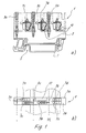
- FIG. 1 shows a terminal block 1 with an insulating material housing 3 with means 5 for snapping onto a mounting rail (not shown here) and a total of five Conductor connections 7a, 7b, ... 7e, with three of the conductor connections - 7a, 7b, 7c - in one arranged perpendicular to the mounting rail extension first row are and wherein the two further conductor connections - 7d, 7e - in one to the first Row parallel second row are arranged.
- the insulating material housing 3 has two shells formed and thus has two housing halves 3a, 3b.
- transverse bridge 9 is laterally offset from the Arrange conductor connections and align them perpendicular to the mounting rail Busbar pieces 11 to connect to the conductor connections, the Transverse jumper 9 perpendicular to the conductor connection rows over the two rows of Extend conductor connections.
- the conductor connections 7a and 7d are conductively connected to one another. The number and execution each of the conductor connections provided in a terminal block housing can be designed as required.
- connections 7d and 7e there is which between these connections to the outer edge of the terminal block, a space for a relative large-scale marking 13 available.
- the conductor connections 7c and 7e are located not directly next to each other but perpendicular to the mounting rail moves what optically facilitates the assignment of cross bridges.
- the terminal block designed in this way - which can also be configured as a block variant - with several rows of conductor connections 7 builds perpendicular to the mounting rail clearly shorter than a comparable terminal block, in which all conductor connections 7 lie in a single row and still allow easy continuation of potentials via several terminal blocks arranged side by side time.
- the terminal block is therefore particularly suitable for installation situations in that only a relatively short space is available on both sides of the mounting rail.
- conductor connections 7 are only exemplary as tension spring connections are trained.
- the conductor connections 7 can also be in any other Way e.g. designed as screw connections or as insulation displacement connections (IDC) be (not shown here).
- IDC insulation displacement connections
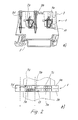
- Fig. 2 shows a terminal block with four conductor connections, in which two connections 7a, 7b are arranged in a first row and connection 7c, 7d offset to this, the cross bridges 9b, 9c can be designed analogously to FIG. 1.
- cross bridge or the cross connection 9 is also not pluggable but integrated cross connection can be formed.
Landscapes
- Coupling Device And Connection With Printed Circuit (AREA)
- Connections Arranged To Contact A Plurality Of Conductors (AREA)
- Lead Frames For Integrated Circuits (AREA)
Abstract
Description
- die Leiteranschlüsse in wenigstens zwei nebeneinander liegenden Reihen angeordnet,
- die Querbrücker seitlich versetzt zu den Leiteranschlüssen angeordnet und erstrecken sich über sämtliche nebeneinander liegende Reihen von Leiteranschlüssen hinweg,
- wobei die in den verschiedenen Reihen nebeneinander liegenden Leiteranschlüsse, welche mit den Querbrückern verbunden sind, zumindest teilweise zum Anschluß unterschiedlicher Potentiale ausgelegt sind.
- Fig. 1a
- eine Seitenansicht einer ersten erfindungsgemäßen Reihenklemme;
- Fig. 1b
- eine Draufsicht auf die Reihenklemme aus Fig. 1a; und
- Fig. 2
- eine Seitenansicht einer zweiten erfindungsgemäßen Reihenklemme.
- Reihenklemme
- 1
- Isolierstoffgehäuse
- 3
- Gehäusehälften
- 3a, 3b
- Aufrastmittel
- 5
- Leiteranschlüsse
- 7
- Querbrücker
- 9
- Stromschienenstücke
- 11
- Kennzeichnung
- 13
- Potentiale
- -, +, PE
Claims (12)
- Reihenklemme mitdadurch gekennzeichnet, daßmehreren Leiteranschlüssen (7) undmindestens einem mit wenigstens einem der Leiteranschlüsse galvanisch verbundenen Querbrücker (9) zur Weiterleitung von Potentialen zu benachbarten weiteren Reihenklemmen (1),die Leiteranschlüsse (7) in wenigstens zwei nebeneinander liegenden Reihen angeordnet sind,die Querbrücker (9) seitlich versetzt zu den Leiteranschlüssen (7) angeordnet sind und sich über sämtliche nebeneinander liegende Reihen von Leiteranschlüssen (7) hinweg erstrecken,wobei die in den verschiedenen Reihen im wesentlichen nebeneinander liegenden Leiteranschlüsse (7), welche mit den Querbrückern (9) verbunden sind, zumindest teilweise zum Anschluß unterschiedlicher Potentiale ausgelegt sind.
- Reihenklemme nach Anspruch 1, dadurch gekennzeichnet, daß das Isolierstoffgehäuse zwei Gehäusehälften (3a, 3b) aufweist.
- Reihenklemme nach einem der vorstehenden Ansprüche, dadurch gekennzeichnet, daß die Querbrücker (9) über senkrecht zur Tragschiene ausgerichtete Stromschienenstücke (11) mit den Leiteranschlüssen (7) verbunden sind.
- Reihenklemme nach Anspruch 1, 2 oder 3, dadurch gekennzeichnet, daß die Leiteranschlüsse (7) als Zugfederanschlüsse ausgebildet sind.
- Reihenklemme nach Anspruch 1, 2 oder 3, dadurch gekennzeichnet, daß die Leiteranschlüsse (7) als Schraubanschlüsse ausgebildet sind.
- Reihenklemme nach Anspruch 1, 2 oder 3, dadurch gekennzeichnet, daß die Leiteranschlüsse (7) als Schneid-/Klemmanschlüsse ausgebildet sind.
- Reihenklemme nach einem der vorstehenden Ansprüche, dadurch gekennzeichnet, daß die Querbrücker (9) steckbar ausgebildet sind.
- Reihenklemme nach einem der vorstehenden Ansprüche, dadurch gekennzeichnet, daß die Reihenklemme als Initiatorklemme oder Aktorklemme ausgelegt ist.
- Reihenklemme nach einem der vorstehenden Ansprüche, dadurch gekennzeichnet, daß n-Leiteranschlüsse vorgesehen sind, wobei n = 2, 3, 4, 5 ist.
- Reihenklemme nach einem der vorstehenden Ansprüche, dadurch gekennzeichnet, daß die Reihen eine unterschiedliche Anzahl von Leiteranschlüssen (7) aufweisen, wobei zwischen zwei der Leiteranschlüssen (7) eine Kennzeichnung (13) anbringbar ist.
- Reihenklemme nach einem der vorstehenden Ansprüche, dadurch gekennzeichnet, daß die nebeneinander liegenden Leiteranschlüsse (7) in den verschiedenen Leiteranschlußreihen senkrecht zur Tragschiene leicht versetzt zueinander angeordnet sind.
- Reihenklemme nach einem der vorstehenden Ansprüche, dadurch gekennzeichnet, die Querverbindungen als integrierte Buchsen/Stecker ausgeführt sind, die sich automatisch beim Aneinanderreihen mehrerer Reihenklemmen miteinander elektrisch verbinden.
Applications Claiming Priority (2)
| Application Number | Priority Date | Filing Date | Title |
|---|---|---|---|
| DE20110681U DE20110681U1 (de) | 2001-06-27 | 2001-06-27 | Reihenklemme mit mehreren Reihen von Anschlüssen und Querbrückern |
| DE20110681U | 2001-06-27 |
Publications (3)
| Publication Number | Publication Date |
|---|---|
| EP1276172A2 true EP1276172A2 (de) | 2003-01-15 |
| EP1276172A3 EP1276172A3 (de) | 2005-07-27 |
| EP1276172B1 EP1276172B1 (de) | 2007-05-02 |
Family
ID=7958632
Family Applications (1)
| Application Number | Title | Priority Date | Filing Date |
|---|---|---|---|
| EP02012820A Expired - Lifetime EP1276172B1 (de) | 2001-06-27 | 2002-06-10 | Reihenklemme mit mehreren Reihen von Anschl-ssen und Querbr-ckern |
Country Status (3)
| Country | Link |
|---|---|
| EP (1) | EP1276172B1 (de) |
| AT (1) | ATE361559T1 (de) |
| DE (2) | DE20110681U1 (de) |
Families Citing this family (1)
| Publication number | Priority date | Publication date | Assignee | Title |
|---|---|---|---|---|
| CN104167273B (zh) * | 2013-12-27 | 2015-07-01 | 上海联影医疗科技有限公司 | 用于磁共振系统的超导磁体 |
Family Cites Families (7)
| Publication number | Priority date | Publication date | Assignee | Title |
|---|---|---|---|---|
| DE3805158A1 (de) * | 1988-02-15 | 1989-08-24 | Wago Verwaltungs Gmbh | Reihenklemme zur zweileiter-stromversorgung von elektrischen oder elektronischen bauelementen, insbesondere initiatoren |
| DE4413643C2 (de) * | 1994-04-20 | 1996-03-28 | Vossloh Schwabe Gmbh | Elektrische Anschluß- und Verbindungsklemme |
| ES2130757T3 (es) * | 1995-02-21 | 1999-07-01 | Legrand Sa | Aparato electrico modular con vaciado en una cara lateral. |
| DE29719177U1 (de) * | 1997-10-29 | 1997-12-04 | Weidmüller Interface GmbH & Co, 32760 Detmold | Reihenklemmenanordnung |
| DE19832593C1 (de) * | 1998-07-09 | 2000-01-05 | Gerd Conrad | Initiatoren-Aktoren-Klemme |
| DE19902745B4 (de) * | 1999-01-25 | 2004-01-15 | Weidmüller Interface Gmbh & Co. | Elektrisches Gerät |
| DE29917491U1 (de) * | 1999-10-05 | 2001-03-22 | Weidmüller Interface GmbH & Co., 32758 Detmold | Reihenklemme |
-
2001
- 2001-06-27 DE DE20110681U patent/DE20110681U1/de not_active Expired - Lifetime
-
2002
- 2002-06-10 AT AT02012820T patent/ATE361559T1/de not_active IP Right Cessation
- 2002-06-10 DE DE50210058T patent/DE50210058D1/de not_active Expired - Lifetime
- 2002-06-10 EP EP02012820A patent/EP1276172B1/de not_active Expired - Lifetime
Also Published As
| Publication number | Publication date |
|---|---|
| EP1276172B1 (de) | 2007-05-02 |
| DE50210058D1 (de) | 2007-06-14 |
| DE20110681U1 (de) | 2002-11-07 |
| EP1276172A3 (de) | 2005-07-27 |
| ATE361559T1 (de) | 2007-05-15 |
Similar Documents
| Publication | Publication Date | Title |
|---|---|---|
| EP1022809B1 (de) | Elektrisches Gerät | |
| EP2053696B1 (de) | Reihenklemmenanordnung mit Verbindern | |
| EP0302814B1 (de) | Anschlussleiste der Fernmeldetechnik | |
| EP1022934B1 (de) | Busleiterabschnitt für ein elektrisches Gerät | |
| EP2491622B1 (de) | System zur verbindung elektrischer leiter mit voneinander verschiedenen potentialen sowie steckadapter für das system | |
| DE19902745B4 (de) | Elektrisches Gerät | |
| DE102004018554A1 (de) | Brücker für elektrische Klemmen | |
| EP0913884B1 (de) | Reihenklemmenanordnung | |
| DE102009030645B4 (de) | Brückerelement und Set aus zumindest einem Klemmelement und Brückerelement | |
| EP2165553A1 (de) | Anschlussleiste und kontaktelement für die telekommunikations- und datentechnik | |
| DE102007026095A1 (de) | Erdkamm, insbesondere für einen Steckverbinder für Leiterplatten | |
| EP1239544A2 (de) | Elektrisches Gerät mit Busleiterabschnitt | |
| DE3910913C2 (de) | Pneumatische oder hydraulische Ventileinheit | |
| EP0822612B1 (de) | Reihenklemme, insbesondere Initiatoren-Aktoren-Klemme | |
| DE3943752C2 (de) | Pneumatische oder hydraulische Ventileinheit | |
| DE2315838B2 (de) | Sicherungsleiste mit einer Mehrzahl elektrischer Sicherungen | |
| DE202009001855U1 (de) | Rangierklemme in Etagenbauform | |
| EP0645856B1 (de) | Verfahren zur Herstellung von Kontaktelemente-Gruppen für Steckverbinder | |
| DE29514014U1 (de) | Reihenklemme mit Stromschiene | |
| EP1432076B1 (de) | Elektrische Verbindungsklemme, insbesondere Reihenklemme | |
| EP1085605B1 (de) | Busleiterabschnitt für ein elektrisches Gerät | |
| DE10212511B4 (de) | Querverbinder für Reihenklemmen | |
| EP1276172B1 (de) | Reihenklemme mit mehreren Reihen von Anschl-ssen und Querbr-ckern | |
| EP3413400B1 (de) | Querverbinderkamm | |
| LU500973B1 (de) | Steckeinrichtung und Bausatz mit einer Steckeinrichtung |
Legal Events
| Date | Code | Title | Description |
|---|---|---|---|
| PUAI | Public reference made under article 153(3) epc to a published international application that has entered the european phase |
Free format text: ORIGINAL CODE: 0009012 |
|
| AK | Designated contracting states |
Kind code of ref document: A2 Designated state(s): AT BE CH CY DE DK ES FI FR GB GR IE IT LI LU MC NL PT SE TR |
|
| AX | Request for extension of the european patent |
Free format text: AL;LT;LV;MK;RO;SI |
|
| PUAL | Search report despatched |
Free format text: ORIGINAL CODE: 0009013 |
|
| AK | Designated contracting states |
Kind code of ref document: A3 Designated state(s): AT BE CH CY DE DK ES FI FR GB GR IE IT LI LU MC NL PT SE TR |
|
| AX | Request for extension of the european patent |
Extension state: AL LT LV MK RO SI |
|
| 17P | Request for examination filed |
Effective date: 20050812 |
|
| AKX | Designation fees paid |
Designated state(s): AT BE CH CY DE DK ES FI FR GB GR IE IT LI LU MC NL PT SE TR |
|
| GRAP | Despatch of communication of intention to grant a patent |
Free format text: ORIGINAL CODE: EPIDOSNIGR1 |
|
| GRAS | Grant fee paid |
Free format text: ORIGINAL CODE: EPIDOSNIGR3 |
|
| GRAA | (expected) grant |
Free format text: ORIGINAL CODE: 0009210 |
|
| AK | Designated contracting states |
Kind code of ref document: B1 Designated state(s): AT BE CH CY DE DK ES FI FR GB GR IE IT LI LU MC NL PT SE TR |
|
| PG25 | Lapsed in a contracting state [announced via postgrant information from national office to epo] |
Ref country code: FI Free format text: LAPSE BECAUSE OF FAILURE TO SUBMIT A TRANSLATION OF THE DESCRIPTION OR TO PAY THE FEE WITHIN THE PRESCRIBED TIME-LIMIT Effective date: 20070502 |
|
| REG | Reference to a national code |
Ref country code: GB Ref legal event code: FG4D Free format text: NOT ENGLISH |
|
| REG | Reference to a national code |
Ref country code: CH Ref legal event code: EP |
|
| REG | Reference to a national code |
Ref country code: IE Ref legal event code: FG4D Free format text: LANGUAGE OF EP DOCUMENT: GERMAN |
|
| REF | Corresponds to: |
Ref document number: 50210058 Country of ref document: DE Date of ref document: 20070614 Kind code of ref document: P |
|
| PG25 | Lapsed in a contracting state [announced via postgrant information from national office to epo] |
Ref country code: SE Free format text: LAPSE BECAUSE OF FAILURE TO SUBMIT A TRANSLATION OF THE DESCRIPTION OR TO PAY THE FEE WITHIN THE PRESCRIBED TIME-LIMIT Effective date: 20070802 |
|
| PG25 | Lapsed in a contracting state [announced via postgrant information from national office to epo] |
Ref country code: ES Free format text: LAPSE BECAUSE OF FAILURE TO SUBMIT A TRANSLATION OF THE DESCRIPTION OR TO PAY THE FEE WITHIN THE PRESCRIBED TIME-LIMIT Effective date: 20070813 |
|
| NLV1 | Nl: lapsed or annulled due to failure to fulfill the requirements of art. 29p and 29m of the patents act | ||
| GBV | Gb: ep patent (uk) treated as always having been void in accordance with gb section 77(7)/1977 [no translation filed] |
Effective date: 20070502 |
|
| REG | Reference to a national code |
Ref country code: IE Ref legal event code: FD4D |
|
| EN | Fr: translation not filed | ||
| BERE | Be: lapsed |
Owner name: WEIDMULLER INTERFACE G.M.B.H. & CO. Effective date: 20070630 |
|
| PG25 | Lapsed in a contracting state [announced via postgrant information from national office to epo] |
Ref country code: MC Free format text: LAPSE BECAUSE OF NON-PAYMENT OF DUE FEES Effective date: 20070630 Ref country code: IE Free format text: LAPSE BECAUSE OF FAILURE TO SUBMIT A TRANSLATION OF THE DESCRIPTION OR TO PAY THE FEE WITHIN THE PRESCRIBED TIME-LIMIT Effective date: 20070502 Ref country code: DK Free format text: LAPSE BECAUSE OF FAILURE TO SUBMIT A TRANSLATION OF THE DESCRIPTION OR TO PAY THE FEE WITHIN THE PRESCRIBED TIME-LIMIT Effective date: 20070502 Ref country code: PT Free format text: LAPSE BECAUSE OF FAILURE TO SUBMIT A TRANSLATION OF THE DESCRIPTION OR TO PAY THE FEE WITHIN THE PRESCRIBED TIME-LIMIT Effective date: 20071002 Ref country code: NL Free format text: LAPSE BECAUSE OF FAILURE TO SUBMIT A TRANSLATION OF THE DESCRIPTION OR TO PAY THE FEE WITHIN THE PRESCRIBED TIME-LIMIT Effective date: 20070502 |
|
| REG | Reference to a national code |
Ref country code: CH Ref legal event code: PL |
|
| PLBE | No opposition filed within time limit |
Free format text: ORIGINAL CODE: 0009261 |
|
| STAA | Information on the status of an ep patent application or granted ep patent |
Free format text: STATUS: NO OPPOSITION FILED WITHIN TIME LIMIT |
|
| PG25 | Lapsed in a contracting state [announced via postgrant information from national office to epo] |
Ref country code: BE Free format text: LAPSE BECAUSE OF NON-PAYMENT OF DUE FEES Effective date: 20070630 |
|
| 26N | No opposition filed |
Effective date: 20080205 |
|
| PG25 | Lapsed in a contracting state [announced via postgrant information from national office to epo] |
Ref country code: LI Free format text: LAPSE BECAUSE OF NON-PAYMENT OF DUE FEES Effective date: 20070630 Ref country code: IT Free format text: LAPSE BECAUSE OF FAILURE TO SUBMIT A TRANSLATION OF THE DESCRIPTION OR TO PAY THE FEE WITHIN THE PRESCRIBED TIME-LIMIT Effective date: 20070502 Ref country code: GR Free format text: LAPSE BECAUSE OF FAILURE TO SUBMIT A TRANSLATION OF THE DESCRIPTION OR TO PAY THE FEE WITHIN THE PRESCRIBED TIME-LIMIT Effective date: 20070803 Ref country code: GB Free format text: LAPSE BECAUSE OF FAILURE TO SUBMIT A TRANSLATION OF THE DESCRIPTION OR TO PAY THE FEE WITHIN THE PRESCRIBED TIME-LIMIT Effective date: 20070502 Ref country code: FR Free format text: LAPSE BECAUSE OF FAILURE TO SUBMIT A TRANSLATION OF THE DESCRIPTION OR TO PAY THE FEE WITHIN THE PRESCRIBED TIME-LIMIT Effective date: 20071228 Ref country code: CH Free format text: LAPSE BECAUSE OF NON-PAYMENT OF DUE FEES Effective date: 20070630 |
|
| PG25 | Lapsed in a contracting state [announced via postgrant information from national office to epo] |
Ref country code: AT Free format text: LAPSE BECAUSE OF NON-PAYMENT OF DUE FEES Effective date: 20070610 |
|
| PG25 | Lapsed in a contracting state [announced via postgrant information from national office to epo] |
Ref country code: FR Free format text: LAPSE BECAUSE OF FAILURE TO SUBMIT A TRANSLATION OF THE DESCRIPTION OR TO PAY THE FEE WITHIN THE PRESCRIBED TIME-LIMIT Effective date: 20070502 |
|
| PG25 | Lapsed in a contracting state [announced via postgrant information from national office to epo] |
Ref country code: CY Free format text: LAPSE BECAUSE OF FAILURE TO SUBMIT A TRANSLATION OF THE DESCRIPTION OR TO PAY THE FEE WITHIN THE PRESCRIBED TIME-LIMIT Effective date: 20070502 |
|
| PG25 | Lapsed in a contracting state [announced via postgrant information from national office to epo] |
Ref country code: LU Free format text: LAPSE BECAUSE OF NON-PAYMENT OF DUE FEES Effective date: 20070610 |
|
| PG25 | Lapsed in a contracting state [announced via postgrant information from national office to epo] |
Ref country code: TR Free format text: LAPSE BECAUSE OF FAILURE TO SUBMIT A TRANSLATION OF THE DESCRIPTION OR TO PAY THE FEE WITHIN THE PRESCRIBED TIME-LIMIT Effective date: 20070502 |
|
| PGFP | Annual fee paid to national office [announced via postgrant information from national office to epo] |
Ref country code: DE Payment date: 20190619 Year of fee payment: 18 |
|
| REG | Reference to a national code |
Ref country code: DE Ref legal event code: R119 Ref document number: 50210058 Country of ref document: DE |
|
| PG25 | Lapsed in a contracting state [announced via postgrant information from national office to epo] |
Ref country code: DE Free format text: LAPSE BECAUSE OF NON-PAYMENT OF DUE FEES Effective date: 20210101 |