EP1275918A2 - Machine de fabrication de glace - Google Patents
Machine de fabrication de glace Download PDFInfo
- Publication number
- EP1275918A2 EP1275918A2 EP02014800A EP02014800A EP1275918A2 EP 1275918 A2 EP1275918 A2 EP 1275918A2 EP 02014800 A EP02014800 A EP 02014800A EP 02014800 A EP02014800 A EP 02014800A EP 1275918 A2 EP1275918 A2 EP 1275918A2
- Authority
- EP
- European Patent Office
- Prior art keywords
- ice making
- temperature
- water
- capacity
- detecting means
- Prior art date
- Legal status (The legal status is an assumption and is not a legal conclusion. Google has not performed a legal analysis and makes no representation as to the accuracy of the status listed.)
- Withdrawn
Links
- XLYOFNOQVPJJNP-UHFFFAOYSA-N water Substances O XLYOFNOQVPJJNP-UHFFFAOYSA-N 0.000 claims abstract description 172
- 238000001816 cooling Methods 0.000 claims abstract description 30
- 238000007710 freezing Methods 0.000 claims description 38
- 230000008014 freezing Effects 0.000 claims description 38
- 230000006835 compression Effects 0.000 claims description 22
- 238000007906 compression Methods 0.000 claims description 22
- 230000008859 change Effects 0.000 claims description 13
- 230000008020 evaporation Effects 0.000 claims description 12
- 238000001704 evaporation Methods 0.000 claims description 12
- 239000003507 refrigerant Substances 0.000 claims description 12
- 238000005259 measurement Methods 0.000 abstract description 30
- 238000000034 method Methods 0.000 description 16
- 238000010586 diagram Methods 0.000 description 15
- 238000010276 construction Methods 0.000 description 12
- 230000000873 masking effect Effects 0.000 description 8
- 230000007246 mechanism Effects 0.000 description 8
- 230000005494 condensation Effects 0.000 description 4
- 238000009833 condensation Methods 0.000 description 4
- 230000005856 abnormality Effects 0.000 description 3
- 230000007257 malfunction Effects 0.000 description 3
- 230000002093 peripheral effect Effects 0.000 description 3
- 230000000903 blocking effect Effects 0.000 description 2
- 238000013461 design Methods 0.000 description 2
- 230000002159 abnormal effect Effects 0.000 description 1
- 239000000853 adhesive Substances 0.000 description 1
- 230000001070 adhesive effect Effects 0.000 description 1
- 238000007796 conventional method Methods 0.000 description 1
- 238000001514 detection method Methods 0.000 description 1
- 238000007599 discharging Methods 0.000 description 1
- 230000000694 effects Effects 0.000 description 1
- 235000013410 fast food Nutrition 0.000 description 1
- 235000013305 food Nutrition 0.000 description 1
- 230000006872 improvement Effects 0.000 description 1
- 230000004048 modification Effects 0.000 description 1
- 238000012986 modification Methods 0.000 description 1
- 230000009467 reduction Effects 0.000 description 1
- 230000000452 restraining effect Effects 0.000 description 1
Images


Classifications
-
- F—MECHANICAL ENGINEERING; LIGHTING; HEATING; WEAPONS; BLASTING
- F25—REFRIGERATION OR COOLING; COMBINED HEATING AND REFRIGERATION SYSTEMS; HEAT PUMP SYSTEMS; MANUFACTURE OR STORAGE OF ICE; LIQUEFACTION SOLIDIFICATION OF GASES
- F25C—PRODUCING, WORKING OR HANDLING ICE
- F25C1/00—Producing ice
- F25C1/12—Producing ice by freezing water on cooled surfaces, e.g. to form slabs
- F25C1/14—Producing ice by freezing water on cooled surfaces, e.g. to form slabs to form thin sheets which are removed by scraping or wedging, e.g. in the form of flakes
- F25C1/145—Producing ice by freezing water on cooled surfaces, e.g. to form slabs to form thin sheets which are removed by scraping or wedging, e.g. in the form of flakes from the inner walls of cooled bodies
- F25C1/147—Producing ice by freezing water on cooled surfaces, e.g. to form slabs to form thin sheets which are removed by scraping or wedging, e.g. in the form of flakes from the inner walls of cooled bodies by using augers
-
- F—MECHANICAL ENGINEERING; LIGHTING; HEATING; WEAPONS; BLASTING
- F25—REFRIGERATION OR COOLING; COMBINED HEATING AND REFRIGERATION SYSTEMS; HEAT PUMP SYSTEMS; MANUFACTURE OR STORAGE OF ICE; LIQUEFACTION SOLIDIFICATION OF GASES
- F25C—PRODUCING, WORKING OR HANDLING ICE
- F25C1/00—Producing ice
- F25C1/22—Construction of moulds; Filling devices for moulds
- F25C1/24—Construction of moulds; Filling devices for moulds for refrigerators, e.g. freezing trays
-
- F—MECHANICAL ENGINEERING; LIGHTING; HEATING; WEAPONS; BLASTING
- F25—REFRIGERATION OR COOLING; COMBINED HEATING AND REFRIGERATION SYSTEMS; HEAT PUMP SYSTEMS; MANUFACTURE OR STORAGE OF ICE; LIQUEFACTION SOLIDIFICATION OF GASES
- F25B—REFRIGERATION MACHINES, PLANTS OR SYSTEMS; COMBINED HEATING AND REFRIGERATION SYSTEMS; HEAT PUMP SYSTEMS
- F25B2600/00—Control issues
- F25B2600/11—Fan speed control
- F25B2600/111—Fan speed control of condenser fans
-
- F—MECHANICAL ENGINEERING; LIGHTING; HEATING; WEAPONS; BLASTING
- F25—REFRIGERATION OR COOLING; COMBINED HEATING AND REFRIGERATION SYSTEMS; HEAT PUMP SYSTEMS; MANUFACTURE OR STORAGE OF ICE; LIQUEFACTION SOLIDIFICATION OF GASES
- F25C—PRODUCING, WORKING OR HANDLING ICE
- F25C2400/00—Auxiliary features or devices for producing, working or handling ice
- F25C2400/14—Water supply
-
- F—MECHANICAL ENGINEERING; LIGHTING; HEATING; WEAPONS; BLASTING
- F25—REFRIGERATION OR COOLING; COMBINED HEATING AND REFRIGERATION SYSTEMS; HEAT PUMP SYSTEMS; MANUFACTURE OR STORAGE OF ICE; LIQUEFACTION SOLIDIFICATION OF GASES
- F25C—PRODUCING, WORKING OR HANDLING ICE
- F25C2600/00—Control issues
- F25C2600/02—Timing
-
- F—MECHANICAL ENGINEERING; LIGHTING; HEATING; WEAPONS; BLASTING
- F25—REFRIGERATION OR COOLING; COMBINED HEATING AND REFRIGERATION SYSTEMS; HEAT PUMP SYSTEMS; MANUFACTURE OR STORAGE OF ICE; LIQUEFACTION SOLIDIFICATION OF GASES
- F25C—PRODUCING, WORKING OR HANDLING ICE
- F25C2600/00—Control issues
- F25C2600/04—Control means
-
- F—MECHANICAL ENGINEERING; LIGHTING; HEATING; WEAPONS; BLASTING
- F25—REFRIGERATION OR COOLING; COMBINED HEATING AND REFRIGERATION SYSTEMS; HEAT PUMP SYSTEMS; MANUFACTURE OR STORAGE OF ICE; LIQUEFACTION SOLIDIFICATION OF GASES
- F25C—PRODUCING, WORKING OR HANDLING ICE
- F25C2700/00—Sensing or detecting of parameters; Sensors therefor
- F25C2700/04—Level of water
-
- Y—GENERAL TAGGING OF NEW TECHNOLOGICAL DEVELOPMENTS; GENERAL TAGGING OF CROSS-SECTIONAL TECHNOLOGIES SPANNING OVER SEVERAL SECTIONS OF THE IPC; TECHNICAL SUBJECTS COVERED BY FORMER USPC CROSS-REFERENCE ART COLLECTIONS [XRACs] AND DIGESTS
- Y02—TECHNOLOGIES OR APPLICATIONS FOR MITIGATION OR ADAPTATION AGAINST CLIMATE CHANGE
- Y02B—CLIMATE CHANGE MITIGATION TECHNOLOGIES RELATED TO BUILDINGS, e.g. HOUSING, HOUSE APPLIANCES OR RELATED END-USER APPLICATIONS
- Y02B30/00—Energy efficient heating, ventilation or air conditioning [HVAC]
- Y02B30/70—Efficient control or regulation technologies, e.g. for control of refrigerant flow, motor or heating
Definitions
- the present invention relates to an ice making machine and, in particular, to an improved ice making machine in which the freezing capacity of a freezing circuit is adjusted by detecting the ice making capacity of the ice making machine, thereby controlling the ice making capacity.
- an auger type ice making machine its ice making mechanism comprises a drive motor (geared motor), a housing, a freezing casing, an auger (screw), etc., and ice making water supplied from a water supply tank to a cylinder contained in the freezing casing is stored while maintaining a fixed water level, ice being made continuously during operation of the ice making mechanism.
- Refrigerant flows through an evaporator, and ice gradually grows on the inner wall surface of the ice making cylinder. This ice is scraped off by a screw rotated by the geared motor, conveyed upwards, and cut into small pieces by a cutter (hereinafter also referred to as a stationary blade).
- the freezing circuit comprises an electric compressor, a condenser, a dehydrator, a thermal expansion valve, an evaporator, etc., and contains refrigerant therein.
- refrigerant at high temperature is cooled by a condenser cooling fan and is liquefied.
- Ice made by an auger type ice making machine is often used in an ice bed or the like for cooling drinks, foods, etc. in a fast-food restaurant; the amount of ice used is maximum in the summer, when the atmospheric temperature is high.
- the ice making machine is designed such that its cooling capacity satisfies demands corresponding to high temperature.
- the refrigerant gas is cooled efficiently or inefficiently according to changes in the atmospheric temperature and water temperature, thereby indicating the capacity of the machine.
- the ice making capacity gradually deteriorates as the temperature and water temperature increase; depending upon the condition for the design spec capacity, the spec capacity varies under different conditions.
- Japanese Patent Laid Open No. 06-207768 discloses a technique according to which the temperatures of the condenser and the evaporator are measured, and the RPM (revolutions per minute) of the drive motor is varied according to the measurements to thereby avoid the above problem.
- Japanese Patent Laid Open Nos. 61-125566 and 09-303914 disclose a technique according to which the ice making capacity is controlled according to variation in a detected current value; the detection of a current value, however, is subject to the influence of fluctuations in voltage. Further, the difference between normal and abnormal current values is rather small, so that it is extremely difficult to recognize.
- This invention has been made with a view toward solving the above problems in the prior art. It is an object of this invention to provide an ice making machine whose ice making capacity is optimally controlled according to the environment in which ice making operation is performed, whereby an excess in ice making capacity is eliminated, thereby achieving a reduction in the consumption of electric power and water and preventing failure and breakage of the ice making mechanism portion so as to achieve an increase in service life.
- an ice making machine comprising: an ice making portion; a water supply tank for supplying ice making water to the ice making portion; a freezing circuit including an evaporator for cooling ice making water supplied to the ice making portion to make ice; ice making capacity detecting means for detecting fluctuation in ice making capacity; and a control circuit which adjusts the freezing capacity of the freezing circuit whenever fluctuation in ice making capacity is detected by the ice making capacity detecting means.
- the ice making capacity detecting means can be constructed such that it detects fluctuation in ice making capacity by comparing one of the following factors with the corresponding reference values:
- the reference value may be adjusted based on the atmospheric temperature or the temperature of the ice making water.
- control circuit It is desirable for the control circuit to be constructed so as to adjust the RPM of the fan motor of the condenser of the freezing circuit or the RPM of the compressor of the freezing circuit.
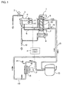
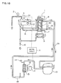
- FIG. 1 is a diagram showing the water route and the freezing circuit of an auger type ice making machine to which this embodiment is applied;
- Fig. 2 is a longitudinal sectional view of a water supply tank;
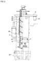
- Fig. 3 is a side view, partially in longitudinal section, of the ice making mechanism portion of the auger-type ice making machine;
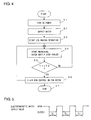
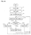
- Fig. 4 is a flowchart illustrating the operation of Embodiment 1;
- Fig. 5 is a timing chart illustrating water supply stop timing for an electromagnetic water supply valve.
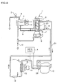
- the water route of the auger type ice making machine 1 is formed by an electromagnetic water supply valve 2, a water supply pipe 3, a water supply tank 4, a supply pipe 6 for supplying ice making water to a cylinder 5, a drain pipe 7 for draining the water in the cylinder 5, and an overflow drain pipe 10 for discharging water overflowing from the water supply tank 4 and upper and lower drain pans 8 and 9.
- a water level detecting switch 11 for detecting the level of the ice making water; when its float 12 is at level A, the water level detecting switch 11 is turned ON, and the electromagnetic water supply valve 2 is opened to supply ice making water to the water supply tank 4.
- the float 12 is raised to reach level B, the water level detecting switch 11 is turned OFF, and with this, the electromagnetic water supply valve 2 is closed to stop the water supply to the water supply tank 4.
- the water level detecting switch 11 is turned ON next, that is, until the electromagnetic water supply valve 2 starts the next opening operation, all the ice making water in the water supply tank 4 is turned into ice by the auger type ice making machine 1, which makes ice continuously.
- the freezing circuit of the auger type ice making machine 1 is formed by a compressor 13, a pressure switch 14, a condenser 15, a fan motor 17 for driving a fan 16 for cooling the condenser 15, a dehydrator 18, a thermal expansion valve 19, an evaporator 20, and a freezing passage 21; refrigerant flows through the refrigerant passage 21 in the direction of the arrow in Fig. 1.
- the fan motor 17 consists, for example, of a DC motor, whose RPM is varied by a control circuit A as appropriate.
- the water level detecting switch 11 constitutes the ice making capacity detecting means of this invention.
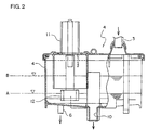
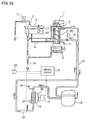
- the ice making mechanism portion of the auger type ice making machine 1 comprises a vertically arranged cylinder 5, an evaporator 20 wound around the outer peripheral surface of the cylinder 5 so as to be in face contact therewith, a screw 25 (hereinafter also referred to as “auger") having a spiral blade 24 to be rotated in the cylinder 5 by a driving motor 23, a cutter 26 (hereinafter referred to as "stationary blade"), and a freezing casing 22 covering the entire cylinder 5 so as to insulate the evaporator 20 from the atmospheric air.
- the ice formed on the inner peripheral surface of the cylinder 22 is scraped off upwards by the spiral blade 24 and cut by the cutter 26.
- the ice making capacity detecting means featuring Embodiment 1 will be described with reference to Figs. 4 and 5.
- the RPM of the fan motor 17 for cooling the condenser 15 is reduced according to variation in the ON and OFF times of the water level detecting switch 11 mounted in the water supply tank 4 to lower the condensing capacity on purpose, thereby restraining excessive ice making.
- the water level detecting switch 11 is turned ON, the electromagnetic water supply valve 2 is opened, and water supply to the water supply tank 4 is started.
- the water level detecting switch 11 is turned OFF, whereby the electromagnetic water supply valve 2 is closed, and the water supply is terminated.
- the auger type icemaking machine 1 continues the continuous ice making operation.
- the water level detecting switch 11 detects it and is turned ON, and the electromagnetic water supply valve 2 is opened again to start water supply.
- a predetermined amount of ice making water is supplied to the water supply tank 4; when the ice making water is used up, water supply is conducted again, thus performing continuousice making.
- the icemaking capacity detecting means is based on the following idea: the auger type ice making machine 1 is a machine for continuous ice making, and the water in the water supply tank 4 is all turned into ice, so that, by fixing the capacity of the water supply tank, the length of time from the instant the water level detecting switch 11 is turned OFF to the instant it is turned ON again, that is, the ice making water consumption time, is measured, making it possible to correctly ascertain any fluctuation in ice making capacity.
- the length of time from turning OFF of the water level detecting switch 11 to turning ON of the same is measured so as to indicate ice making water consumption time (Fig. 5).
- an arbitrary reference time T2 is determined so as to be in conformity with temperature conditions where not much ice is required as in the winter.
- the ice making capacity detecting means compares these times T1 and T2 with each other and makes a judgment based upon the comparison result.
- the control circuit A When the water-supply-stop time T1 is not shorter than the reference time T2, the control circuit A does not change the RPM of the fan motor 17. When the water-supply-stop time T1 is shorter than the reference time T2, it determines that there is an excess in ice making capacity, and lowers the RPM of the fan motor 17 to eliminate this excess.
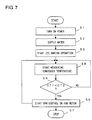
- Embodiment 1 When the power is turned on in step S1, the auger type ice making machine 1 is made ready for operation.
- step S2 the electromagnetic water supply valve 2 is opened, and ice making water is supplied to the water supply tank 4, and, in step S3, the auger type ice making machine 1 starts ice making operation.
- step S4 the water level detecting switch 11 starts measurement.
- step S5 the water-supply-stop time T1 and the reference time T2 are compared with each other; when the water-supply-stop time T1 is not shorter than the reference time T2, the procedure returns to step S4.
- step S6 RPM control on the cooling fan motor 17 for the condenser 15, and effects control so as to reduce the RPM of the fan motor 17.
- This routine is repeatedly executed while the auger type ice making machine 1 is in operation, until the power is turned off in step S7. This makes it possible to correctly ascertain any fluctuation in ice making capacity. For example, in winter, when not much ice is required, the condensing capacity of the condenser 15 is lowered on purpose, whereby it is possible to smoothly avoid excessive ice making and to prevent an excess load from being applied to the ice making mechanism portion.
- Embodiment 1 While in Embodiment 1, RPM control is performed on the fan motor 17 only when the water-supply-stop time T1 is shorter than the reference time T2, it is also possible to form the system such that when the water-supply-stop time T1 is longer than the reference time T2, it is determined that the amount of ice made by the auger type ice making machine has not reached a desired level, and the RPM of the fan motor 17 is increased to achieve an improvement in ice making capacity.
- the ice making machine of Embodiment 1 is equipped with a temperature sensor 27 for detecting the temperature of the condenser 15, and the ice making capacity detecting means is formed by this temperature sensor 27.
- this embodiment is of the same construction as Embodiment 1, so that the following description will be focused on where it differs from Embodiment 1.
- the measurement temperature CT1 of the condenser 15 measured by the temperature sensor 27 is compared with an arbitrary reference temperature CT2. And, when the measurement temperature CT1 measured by the temperature sensor 27 is lower than the reference temperature CT2, the control circuit A performs control so as to reduce the RPM of the fan motor 17, whereby the condensing capacity is lowered on purpose to restrain excessive ice making.
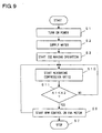
- Embodiment 2 when ice making operation is started in step S3, the temperature sensor 27 starts measurement of the temperature of the condenser 15 in step S8, and the measurement temperature CT1 and the reference temperature CT2 are compared with each other in step S9. And, when it is determined that the measurement temperature CT1 is lower than the reference temperature CT2, the control circuit A determines that the auger type ice making machine 1 is in an excessive-ice-making state, and the procedure advances to step S6, where the RPM control is started on the fan motor 17 for cooling the condenser 15 so as to reduce the RPM of the fan motor 17.
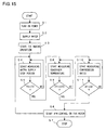
- the ice making machine of Embodiment 1 is equipped with pressure sensors 28 and 29 for detecting the high-pressure-side pressure and the low-pressure-side pressure of the compressor 13, and the ice making capacity detecting means of this invention is formed by the pressure sensors 28 and 29. Since the other structures are the same as those of Embodiment 1, only the points that differ therefrom are explained below. From the high-pressure-side pressure and the low-pressure-side pressure measured by the pressure sensors 28 and 29, a compression ratio A1 is calculated, and this compression ratio A1 is compared with an arbitrary reference value A2. When the compression ratio A1 is lower than the reference value A2, the control circuit A performs control so as to reduce the RPM of the fan motor 17, whereby the condensing capacity is lowered on purpose to thereby restrain excessive ice making.
- step S3 when ice making operation is started in step S3, the pressure sensors start measurement of the compression ratio A1 of the compressor 13 in step S10, and the compression ratio A1 and the reference value A2 are compared with each other in step S11. Then, when it is determined that the compression ratio A1 is lower than the reference value A2, the control circuit A determines that the auger type ice making machine 1 is in an excessive-ice-making state, and the procedure advances to step S6, where the RPM control is started on the fan motor 17 for the condenser 15 so as to reduce the RPM of the fan motor 17.
- the ice making capacity detecting means is formed by the temperature sensor 27 and the water level detecting switch 11.
- the control circuit A performs control so as to reduce the RPM of the fan motor 17, whereby the condensing capacity is lowered on purpose to restrain excessive ice making.
- Embodiment 4 when ice making operation is started in step S3, the water level detecting switch 11 starts measurement in step S4, and then the water-supply-stop time T1 and the reference time T2 are compared with each other in step S5.
- the temperature sensor 27 starts measurement of the temperature of the condenser 15 in step S8, and the measurement temperature CT1 and the reference temperature CT2 are compared with each other in step S9.
- step S9 when it is determined in step S9 that the measurement temperature CT1 is lower than the reference temperature CT2, the control circuit A determines that the auger type ice making machine 1 is in an excessive-ice-making state, and the procedure advances to step S6, where the RPM control is started on the fan motor 17 for cooling the condenser 15 so as to reduce the RPM of the fan motor 17.
- ice making capacity is judged based on the time between turning OFF and turning ON of the water level detecting switch 11, that is, the ice making water consumption time and on the temperature of the condenser 15, and the RPM of the fan motor 17 for the condenser 15 can be controlled, so that if there is any abnormality in the water circuit, such as water leakage or malfunction of the float switch 11, there is little possibility of erroneous judgment.
- the ice making capacity detecting means of this invention is formed by the pressure sensors 28 and 29, and the water level detecting switch 11.
- the control circuit A performs control so as to reduce the RPM of the fan motor 17, whereby the condensing capacity is lowered on purpose to thereby restrain excessive ice making.
- step S3 when ice making operation is started in step S3, the water level detecting switch 11 starts measurement in step S4, and the water-supply-stop time T1 and the reference time T2 are compared with each other in step S5.
- the pressure sensors start measurement of the compression ratio A1 of the compressor 13 in step S10, and then the compression ratio A1 and the reference value A2 are compared with each other in step S11.
- the control circuit A determines that the auger type ice making machine 1 is in an excessive-ice-making state, and the procedure advances to step S6, where the RPM control is started on the fan motor 17 for the condenser 15 so as to reduce the RPM of the fan motor 17.
- the RPM of the fan motor 17 for the condenser 15 can be controlled based on the time between turning OFF and turning ON of the water level detecting switch 11, that is, the ice making water consumption time and on the compression ratio of the compressor 13, so that if there is any abnormality in the water circuit, such as water leakage or malfunction of the float switch 11, there is little possibility of erroneous judgment.
- the ice making machine of Embodiment 2 is further equipped with pressure sensors 28 and 29 for detecting the high-pressure-side pressure and the low-pressure-side pressure of the compressor 13, and the ice making capacity detecting means of this invention is formed by the pressure sensors 28 and 29, the water level detecting switch 11, and the temperature sensor 27 for detecting the temperature of the condenser 15.
- the control circuit A performs control so as to reduce the RPM of the fan motor 17, whereby the condensing capacity is lowered on purpose to thereby restrain excessive ice making.
- step S3 when ice making operation is started in step S3, the water level detecting switch 11 starts measurement in step S4, and the water-supply-stop time T1 and the reference time T2 are compared with each other in step S5.
- the temperature sensor 27 starts measurement of the temperature of the condenser 15 in step S8, and then the measurement temperature CT1 and the reference temperature CT2 are compared with each other in step S9.
- step S10 when it is determined that the measurement temperature CT1 is lower than the reference temperature CT2, the pressure sensors 28 and 29 start measurement of the compression ratio A1 of the compressor 13 in step S10, and the compression ratio A1 and the reference value A2 are compared with each other in step S11.
- the control circuit A determines that the auger type ice making machine 1 is in an excessive-ice-making state, and the procedure advances to step S6, where the RPM control is started on the fan motor 17 for cooling the condenser 15 so as to reduce the RPM of the fan motor 17.
- the RPM of the fan motor 17 for the condenser 15 can be controlled based on the time between turning OFF and turning ON of the water level detecting switch 11, that is, ice making water consumption time, the temperature of the condenser 15, and the compression ratio of the compressor 13, so that if there is any abnormality in the water circuit, such as water leakage or malfunction of the float switch 11, there is little possibility of erroneous judgment.
- the supply pipe 6 of the ice making machine of Embodiment 1 is equipped with a flow meter 30, which constitutes the ice making capacity detecting means of this invention. Ice making water is supplied anew through the supply pipe 6 to the cylinder 5 in an amount corresponding to the amount of the water turned into ice by the cylinder 5 and discharged therefrom.
- a flow meter 30 which constitutes the ice making capacity detecting means of this invention. Ice making water is supplied anew through the supply pipe 6 to the cylinder 5 in an amount corresponding to the amount of the water turned into ice by the cylinder 5 and discharged therefrom.
- the flow rate R1 of the ice making water supplied from the water supply tank 4 to the cylinder 5 by means of the flow meter 30, it is possible to detect the ice making amount per hour.
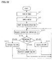
- step S3 when ice making operation is started in step S3, the flow meter 30 starts in step S20 the measurement of the flow rate R1 of the ice making water, and, in step S21, the flow rate R1 is compared with a pre-set reference flow rate R2.
- the control circuit A determines that the auger type ice making machine 1 is in an excessive-ice-making state, and reduces in step S22 the RPM of the cooling fan motor 17 for the condenser 15 to lower the ice making capacity.
- step S21 When it is determined in step S21 that the flow rate R1 is less than the reference flow rate R2, the control circuit A determines that the auger type ice making machine has not attained a desired ice making amount, and increases in step S23 the RPM of the fan motor 17 for cooling the condenser 15 to thereby improve the ice making capacity.
- step S21 When it is determined in step S21 that the flow rate R1 is equal to the reference flow rate R2, the control circuit A maintains in step S24 the current RPM of the cooling fan motor 17. Thereafter, the procedure returns to step S20, and the operations of steps S20 through S24 are repeated.
- the water supply tank 4 of the ice making machine of Embodiment 1 is provided with a water level sensor 31 for detecting the water level of the ice making water; this water level sensor 31 constitutes the ice making capacity detecting means.
- the water level of the ice making water in the water supply tank 4 is lowered by the amount of water turned into ice by the cylinder 5 and discharged therefrom, so that by detecting the water level change amount H1 of the ice making water by the water level sensor 31, it is possible to detect the ice making amount per hour.
- step S3 when ice making operation is started in step S3, the water level sensor 31 starts the measurement of the water level change amount H1 of the ice making water in step S25, and, in step S26, the water level change amount H1 is compared with a pre-set reference change amount H2.
- the control circuit A determines that the auger type ice making machine 1 is in an excessive-ice-making state, and reduces in step S22 the RPM of the fan motor 17 for cooling the condenser 15 to thereby lower the ice making capacity.
- step S26 When it is determined in step S26 that the water level change amount H1 is less than the reference change amount H2, the control circuit A determines that the auger type ice making machine 1 has not attained a desired ice making amount, and increases in step S23 the RPM of the fan motor 17 for cooling the condenser 15 to thereby improve the ice making capacity.
- step S26 When it is determined in step S26 that the water level change amount H1 is equal to the reference change amount H2, the control circuit A maintains in step S24 the current RPM of the cooling fan motor 17. Thereafter, the procedure returns to step S25.
- a temperature sensor 32 is provided at the inlet of the evaporator 20 to measure the evaporation temperature ET1 of the refrigerant in the evaporator 20; the temperature sensor 32 constitutes the ice making capacity detecting means.
- the evaporation temperature ET1 is in proportion to the ice making capacity; by detecting the evaporation temperature ET1, it is possible to detect the ice making amount per hour.
- step S3 when ice making operation is started in step S3, the temperature sensor 32 starts the measurement of the evaporation temperature ET1 of the refrigerant in step S27, and, in step S28, the evaporation temperature ET1 is compared with a pre-set reference temperature ET2.
- the control circuit A determines that the auger type ice making machine 1 is in an excessive-ice-making state, and reduces in step S22 the RPM of the fan motor 17 for cooling the condenser 15 to thereby lower the ice making capacity.
- step S28 When it is determined in step S28 that the evaporation temperature ET1 is higher than the reference temperature ET2, the control circuit A determines that the auger type ice making machine 1 has not attained a desired ice making amount, and increases in step S23 the RPM of the fan motor 17 for cooling the condenser 15 to thereby improve the ice making capacity.
- step S28 When it is determined in step S28 that the evaporation temperature ET1 is equal to the reference temperature ET2, the control circuit A maintains in step S24 the current RPM of the cooling fan motor 17. Thereafter, the procedure returns to step S27.
- a temperature sensor 33 for measuring the atmospheric temperature AT is provided in the ice making machine of Embodiment 2; the ice making capacity detecting means of this invention is formed by this temperature sensor 33 and a temperature sensor 27 for detecting the temperature CT1 of the condenser 15.
- the control circuit A stores beforehand a plurality of reference temperatures CT2 different from each other with respect to the condenser 15.
- the ice making capacity is influenced by the atmospheric temperature AT, so that, in addition to the RPM control performed on the cooling fan motor 17 on the basis of the temperature CT1 of the condenser 15, the reference temperature CT2 of the condenser 15 to be used in the RPM control is selected on the basis of the atmospheric temperature AT, whereby it is possible to appropriately control the ice making capacity according to the environment.
- the temperature sensor 33 measures the atmospheric temperature AT in step S29, and, in step 30, one reference temperature CT2 corresponding to the measurement value of the atmospheric temperature AT obtained by the temperature sensor 33 is selected from among the plurality of reference temperatures CT2 stored in the control circuit A beforehand in step S30. Further, in step S31, the temperature sensor 27 starts the measurement of the temperature CT1 of the condenser 15, and, in step S32, the temperature CT1 is compared with the selected reference temperature CT2.
- the control circuit A determines that the auger type ice making machine 1 is in an excessive-ice-making state, and reduces in step S22 the RPM of the fan motor 17 for cooling the condenser 15 to thereby lower the ice making capacity.
- the control circuit A determines that the auger type ice making machine has not attained a desired ice making amount, and increases in step S23 the RPM of the fan motor 17 of the condenser 15 to thereby improve the ice making capacity.
- the control circuit A maintains in step S24 the current RPM of the cooling fan motor 17. Thereafter, the procedure returns to step S29.
- the temperature sensor 33 for measuring the atmospheric temperature AT may be provided in each of the ice making machines of Embodiments 3-6 and 9 to adjust based on the detected atmospheric temperature AT the reference value A2 in Embodiment 3, the reference temperature CT2 in Embodiment 4, the reference value A2 in Embodiment 5, the reference temperature CT2 and the reference value A2 in Embodiment 6 and the reference temperature ET2 in Embodiment 9.
- the ice making machine of Embodiment 2 is provided with a temperature sensor 34 for measuring the temperature WT of the ice making water in the water supply tank 4, and the ice making capacity detecting means is formed by this temperature sensor 34 and the temperature sensor 27 for detecting the temperature CT1 of the condenser 15.
- the control circuit A stores beforehand a plurality of different reference temperatures CT2 with respect to the condenser 15.
- the ice making capacity is influenced by the temperature WT of the ice making water used for ice making, so that, in addition to the RPM control performed on the cooling fan motor 17 on the basis of the temperature CT1 of the condenser 15, the reference temperature CT2 of the condenser 15 to be used in the RPM control is selected on the basis of the temperature WT of the ice making water, whereby it is possible to appropriately control the ice making capacity according to the environment.
- the temperature sensor 34 measures the temperature WT of the ice making water in step S33, and, in step S30, one reference temperature CT2 corresponding to the measurement value of the temperature WT of the ice making water obtained by the temperature sensor 34 is selected from among the plurality of reference temperatures CT2 stored in the control circuit A beforehand. Further, in step S31, the temperature sensor 27 starts the measurement of the temperature CT1 of the condenser 15, and, in step S32, the temperature CT1 and the selected reference temperature CT2 are compared with each other.
- the control circuit A determines that the auger type ice making machine 1 is in an excessive-ice-making state, and reduces in step S22 the RPM of the fan motor 17 for cooling the condenser 15 to thereby lower the ice making capacity.
- the control circuit A determines that the auger type ice making machine 1 has not attained the desired ice making amount, and increases in step S23 the RPM of the fan motor 17 for cooling the condenser 15 to thereby improve the ice making capacity.
- the control circuit A maintains in step S24 the current RPM of the cooling fan motor 17. Thereafter, the procedure returns to step S33.
- the temperature sensor 34 for measuring the temperature WT of the ice making water in the water supply tank 4 may be provided in each of the ice making machines of Embodiments 3-6 and 9 to adjust based on the detected temperature WT the reference value A2 in Embodiment 3, the reference temperature CT2 in Embodiment 4, the reference value A2 in Embodiment 5, the reference temperature CT2 and the reference value A2 in Embodiment 6 and the reference temperature ET2 in Embodiment 9.
- Embodiments 1 through 11 it is also possible to respectively arrange cooling fans 16 and 35 in front of and behind the condenser 15 and to independently drive them by the fan motors 17 and 36, respectively. This arrangement allows switching between the following four modes:
- RPM control is performed on the fan motor 17 in order to control the condensation capacity of the condenser 15, this should not be construed restrictively. It is also possible, as shown in Fig. 28, to control the condensation capacity by blocking a desired area of an exhaust heat port 37 of the ice making machine with a masking plate 38. The larger the area of the exhaust heat port 37 blocked by the masking plate 38, the lower the condensation capacity, and the lower the ice making capacity.
- a magnet is mounted by an adhesive double coated tape or the like. Due to this magnet, the masking plate 38 can be easily attached to the outer surface of the ice making machine. Solely by varying the attachment position for the masking plate 38, it is possible to adjust the condensation capacity.
- the masking plate 38 When there is no need to use the masking plate 38, the masking plate 38 is just attached to some outer surface portion of the ice making machine other than the exhaust heat port 37 and is thus stored.
- the freezing capacity of the freezing circuit is adjusted by controlling the RPM of the fan motor 17 for cooling the condenser 15, it is also possible to control the RPM of the compressor 13.
- step S5 when in step S5 the water-supply-stop time T1 is lower than the reference time T2, RPM control is started on the compressor 13 in step S12, making it possible to perform control so as to reduce the RPM of the compressor 13.
- the compressing capacity is lowered on purpose to thereby restrain excessive ice making.
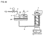
- an ice making machine can be constructed such that the water supply tank 4 is equipped with the temperature sensor 34 and a heater 39 as shown in Fig. 30, and when the temperature WT of the ice making water detected by the temperature sensor 34 is lower than a predetermined value, the ice making water is heated by the heater 39.
- the heater 39 is turned ON when the temperature WT is lower than 10°C while the heater 39 is turned OFF when the temperature WT rises up to 20°C.
- the heater 39 should be controlled so as to keep the temperature WT of the ice making water detected by the temperature sensor 34 to be a predetermined value. If the predetermined value is set to a usual temperature of supplied water such as 20°C, it is necessary to cool water until its temperature is lowered to the predetermined value when water having a temperature of 30°C is supplied. Therefore, the predetermined value is desired to be set to a temperature such as 50°C higher than the usual temperature of supplied water. In this case, it is not necessary to cool water and the temperature WT of the ice making water can be maintained at a constant value by only using the heater 39. Thus, the ice making capacity can be stabilized and generation of unusual noise can be prevented.
- fluctuation in the ice making capacity of an ice making machine is detected by an ice making capacity detecting means; when any fluctuation in the ice making capacity is detected, a control circuit adjusts the freezing capacity of a freezing circuit, whereby an excess in ice making capacity is eliminated, consumption of electric power and water is reduced, and failure or breakage of the ice making mechanism portion is prevented to thereby achieve an increase in service life.
Landscapes
- Engineering & Computer Science (AREA)
- Physics & Mathematics (AREA)
- Mechanical Engineering (AREA)
- Thermal Sciences (AREA)
- General Engineering & Computer Science (AREA)
- Production, Working, Storing, Or Distribution Of Ice (AREA)
Applications Claiming Priority (4)
| Application Number | Priority Date | Filing Date | Title |
|---|---|---|---|
| JP2001207456 | 2001-07-09 | ||
| JP2001207456 | 2001-07-09 | ||
| JP2002179662A JP3828834B2 (ja) | 2001-07-09 | 2002-06-20 | 製氷機 |
| JP2002179662 | 2002-06-20 |
Publications (2)
| Publication Number | Publication Date |
|---|---|
| EP1275918A2 true EP1275918A2 (fr) | 2003-01-15 |
| EP1275918A3 EP1275918A3 (fr) | 2003-10-01 |
Family
ID=26618338
Family Applications (1)
| Application Number | Title | Priority Date | Filing Date |
|---|---|---|---|
| EP02014800A Withdrawn EP1275918A3 (fr) | 2001-07-09 | 2002-07-04 | Machine de fabrication de glace |
Country Status (4)
| Country | Link |
|---|---|
| EP (1) | EP1275918A3 (fr) |
| JP (1) | JP3828834B2 (fr) |
| KR (1) | KR100446827B1 (fr) |
| CN (1) | CN1221772C (fr) |
Cited By (3)
| Publication number | Priority date | Publication date | Assignee | Title |
|---|---|---|---|---|
| KR100446827B1 (ko) * | 2001-07-09 | 2004-09-04 | 호시자키 덴키 가부시키가이샤 | 제빙기 |
| WO2015025236A1 (fr) * | 2013-08-20 | 2015-02-26 | BSH Bosch und Siemens Hausgeräte GmbH | Réfrigérateur et procédé de commande s'y rapportant |
| EP3904790A4 (fr) * | 2018-12-28 | 2022-03-02 | Daikin Industries, Ltd. | Système de fabrication de glace et procédé de fabrication de glace |
Families Citing this family (18)
| Publication number | Priority date | Publication date | Assignee | Title |
|---|---|---|---|---|
| US20060277937A1 (en) * | 2005-06-10 | 2006-12-14 | Manitowoc Foodservice Companies.Inc. | Ice making machine and method of controlling an ice making machine |
| KR101182276B1 (ko) | 2006-12-14 | 2012-09-14 | 삼성전자주식회사 | 냉장고 및 그 제어방법 |
| CN100434842C (zh) * | 2007-05-25 | 2008-11-19 | 周武峰 | 一种流水式制冰机制冰块大小的控制方法 |
| KR101039052B1 (ko) | 2008-08-05 | 2011-06-07 | 코리아나까조 주식회사 | 제빙기의 정수위조절장치 |
| JP5262748B2 (ja) * | 2009-01-22 | 2013-08-14 | 富士電機株式会社 | 製氷機の制御装置 |
| CN103162483A (zh) * | 2011-12-09 | 2013-06-19 | 上海酒店设备股份有限公司 | 具有制冷系统高温高压双重保护功能的制冰机 |
| CN105571231B (zh) * | 2013-04-27 | 2018-11-06 | 三菱重工冷热株式会社 | 风雪形成装置 |
| JP2016223729A (ja) * | 2015-06-02 | 2016-12-28 | ホシザキ株式会社 | 製氷機 |
| JP6767097B2 (ja) * | 2015-06-15 | 2020-10-14 | ホシザキ株式会社 | 製氷機 |
| WO2018107538A1 (fr) * | 2016-12-16 | 2018-06-21 | 芜湖美的厨卫电器制造有限公司 | Machine à glaçons, dispositif de détection de niveau d'eau et procédé de détection de niveau d'eau associés |
| CN108007030B (zh) * | 2016-12-16 | 2020-02-14 | 芜湖美的厨卫电器制造有限公司 | 制冰机及其水位检测装置和水位检测方法 |
| KR101936748B1 (ko) * | 2017-06-23 | 2019-04-09 | 코웨이 주식회사 | 제빙 기능을 구비한 정수기 및 이의 동작 방법 |
| WO2020071789A1 (fr) * | 2018-10-02 | 2020-04-09 | 엘지전자 주식회사 | Réfrigérateur et son procédé de commande |
| JP6760361B2 (ja) * | 2018-12-27 | 2020-09-23 | ダイキン工業株式会社 | 製氷機の運転制御方法 |
| JP2021004718A (ja) * | 2019-06-27 | 2021-01-14 | 大和冷機工業株式会社 | オーガ式製氷機 |
| CN114279123B (zh) * | 2021-12-29 | 2024-10-11 | 滁州东菱电器有限公司 | 制冰机及控制方法 |
| CN116518603A (zh) * | 2023-04-04 | 2023-08-01 | 广东美的白色家电技术创新中心有限公司 | 制冰设备、控制方法和存储介质 |
| CN116518602A (zh) * | 2023-04-04 | 2023-08-01 | 广东美的白色家电技术创新中心有限公司 | 制冰设备、控制方法和存储介质 |
Citations (6)
| Publication number | Priority date | Publication date | Assignee | Title |
|---|---|---|---|---|
| JPS57142466A (en) | 1981-02-27 | 1982-09-03 | Sanyo Electric Co | Motor driver for auger type ice making machine |
| JPS5947172A (ja) | 1982-09-11 | 1984-03-16 | トヨタ自動車株式会社 | 低騒音型チツピングハンマ |
| JPS61125566A (ja) | 1984-11-20 | 1986-06-13 | 三洋電機株式会社 | オ−ガ−式製氷装置の保護装置 |
| JPH06207768A (ja) | 1993-01-08 | 1994-07-26 | Sanyo Electric Co Ltd | オーガー式製氷機の制御装置 |
| JPH08178487A (ja) | 1994-12-27 | 1996-07-12 | Fuji Electric Co Ltd | オーガ式製氷機 |
| JPH09303914A (ja) | 1996-05-13 | 1997-11-28 | Sanyo Electric Co Ltd | 製氷機 |
Family Cites Families (7)
| Publication number | Priority date | Publication date | Assignee | Title |
|---|---|---|---|---|
| JPS5417450B2 (fr) * | 1974-05-17 | 1979-06-29 | ||
| US4644757A (en) * | 1985-02-12 | 1987-02-24 | Hoshizaki Electric Co., Ltd. | Auger type ice-making apparatus |
| US4982573A (en) * | 1989-04-25 | 1991-01-08 | Hoshizaki Denki Kabushiki Kaisha | Electric control apparatus for auger type ice making machine |
| US5129237A (en) * | 1989-06-26 | 1992-07-14 | Servend International, Inc. | Ice making machine with freeze and harvest control |
| US5477694A (en) * | 1994-05-18 | 1995-12-26 | Scotsman Group, Inc. | Method for controlling an ice making machine and apparatus therefor |
| JPH09303916A (ja) * | 1996-05-14 | 1997-11-28 | Hoshizaki Electric Co Ltd | 水循環式製氷機 |
| JP3828834B2 (ja) * | 2001-07-09 | 2006-10-04 | ホシザキ電機株式会社 | 製氷機 |
-
2002
- 2002-06-20 JP JP2002179662A patent/JP3828834B2/ja not_active Expired - Lifetime
- 2002-07-04 EP EP02014800A patent/EP1275918A3/fr not_active Withdrawn
- 2002-07-08 CN CNB02141162XA patent/CN1221772C/zh not_active Expired - Fee Related
- 2002-07-09 KR KR10-2002-0039676A patent/KR100446827B1/ko not_active Expired - Fee Related
Patent Citations (6)
| Publication number | Priority date | Publication date | Assignee | Title |
|---|---|---|---|---|
| JPS57142466A (en) | 1981-02-27 | 1982-09-03 | Sanyo Electric Co | Motor driver for auger type ice making machine |
| JPS5947172A (ja) | 1982-09-11 | 1984-03-16 | トヨタ自動車株式会社 | 低騒音型チツピングハンマ |
| JPS61125566A (ja) | 1984-11-20 | 1986-06-13 | 三洋電機株式会社 | オ−ガ−式製氷装置の保護装置 |
| JPH06207768A (ja) | 1993-01-08 | 1994-07-26 | Sanyo Electric Co Ltd | オーガー式製氷機の制御装置 |
| JPH08178487A (ja) | 1994-12-27 | 1996-07-12 | Fuji Electric Co Ltd | オーガ式製氷機 |
| JPH09303914A (ja) | 1996-05-13 | 1997-11-28 | Sanyo Electric Co Ltd | 製氷機 |
Cited By (3)
| Publication number | Priority date | Publication date | Assignee | Title |
|---|---|---|---|---|
| KR100446827B1 (ko) * | 2001-07-09 | 2004-09-04 | 호시자키 덴키 가부시키가이샤 | 제빙기 |
| WO2015025236A1 (fr) * | 2013-08-20 | 2015-02-26 | BSH Bosch und Siemens Hausgeräte GmbH | Réfrigérateur et procédé de commande s'y rapportant |
| EP3904790A4 (fr) * | 2018-12-28 | 2022-03-02 | Daikin Industries, Ltd. | Système de fabrication de glace et procédé de fabrication de glace |
Also Published As
| Publication number | Publication date |
|---|---|
| JP3828834B2 (ja) | 2006-10-04 |
| CN1396425A (zh) | 2003-02-12 |
| EP1275918A3 (fr) | 2003-10-01 |
| KR100446827B1 (ko) | 2004-09-04 |
| KR20030007077A (ko) | 2003-01-23 |
| JP2003090657A (ja) | 2003-03-28 |
| CN1221772C (zh) | 2005-10-05 |
Similar Documents
| Publication | Publication Date | Title |
|---|---|---|
| EP1275918A2 (fr) | Machine de fabrication de glace | |
| US6601399B2 (en) | Ice making machine | |
| CN114777395B (zh) | 冰箱的控制方法 | |
| US8726680B2 (en) | Electronic refrigeration control system including a variable speed compressor | |
| US7886549B2 (en) | Refrigeration system | |
| JP5256692B2 (ja) | 燃料電池システム | |
| EP2719976B1 (fr) | Appareil de réfrigération | |
| US20090007575A1 (en) | Cooling apparatus | |
| KR20030063197A (ko) | 오거식 제빙기 | |
| KR20190112482A (ko) | 냉장고 및 그 제어방법 | |
| CN103913024B (zh) | 用于控制变速压缩机的速度的方法 | |
| JP2000039240A (ja) | 製氷機 | |
| US20070151269A1 (en) | System and method for level control in a flash tank | |
| CN103906985B (zh) | 具有蒸发盘的制冷器具 | |
| CN120488575B (zh) | 一种抗结冰的制冷方法及系统 | |
| JPH0979710A (ja) | 冷凍装置の除霜制御装置 | |
| CN114508808A (zh) | 一种磁悬浮变频冷水机组 | |
| CN212619639U (zh) | 冷藏冷冻装置及其蒸发器化霜控制装置 | |
| JPH08334285A (ja) | 冷蔵庫 | |
| CN108954714B (zh) | 空调器的启动控制方法和空调器 | |
| JP3690229B2 (ja) | ヒートポンプ給湯機 | |
| JP5329332B2 (ja) | 製氷機 | |
| JP2000356441A (ja) | オーガ式製氷機の制御装置 | |
| CN119617767B (zh) | 一种变频冰箱化霜周期确定方法 | |
| KR101059817B1 (ko) | 냉동시스템의 전력전자 부품 냉각장치 |
Legal Events
| Date | Code | Title | Description |
|---|---|---|---|
| PUAI | Public reference made under article 153(3) epc to a published international application that has entered the european phase |
Free format text: ORIGINAL CODE: 0009012 |
|
| AK | Designated contracting states |
Kind code of ref document: A2 Designated state(s): AT BE BG CH CY CZ DE DK EE ES FI FR GB GR IE IT LI LU MC NL PT SE SK TR |
|
| AX | Request for extension of the european patent |
Free format text: AL;LT;LV;MK;RO;SI |
|
| PUAL | Search report despatched |
Free format text: ORIGINAL CODE: 0009013 |
|
| AK | Designated contracting states |
Kind code of ref document: A3 Designated state(s): AT BE BG CH CY CZ DE DK EE ES FI FR GB GR IE IT LI LU MC NL PT SE SK TR |
|
| AX | Request for extension of the european patent |
Extension state: AL LT LV MK RO SI |
|
| 17P | Request for examination filed |
Effective date: 20030922 |
|
| AKX | Designation fees paid |
Designated state(s): DE FR IT |
|
| 17Q | First examination report despatched |
Effective date: 20041125 |
|
| STAA | Information on the status of an ep patent application or granted ep patent |
Free format text: STATUS: THE APPLICATION IS DEEMED TO BE WITHDRAWN |
|
| 18D | Application deemed to be withdrawn |
Effective date: 20101012 |