EP1275868A1 - Einwegkupplungseinheit - Google Patents
Einwegkupplungseinheit Download PDFInfo
- Publication number
- EP1275868A1 EP1275868A1 EP02015417A EP02015417A EP1275868A1 EP 1275868 A1 EP1275868 A1 EP 1275868A1 EP 02015417 A EP02015417 A EP 02015417A EP 02015417 A EP02015417 A EP 02015417A EP 1275868 A1 EP1275868 A1 EP 1275868A1
- Authority
- EP
- European Patent Office
- Prior art keywords
- way clutch
- inner ring
- piece
- ring part
- outer ring
- Prior art date
- Legal status (The legal status is an assumption and is not a legal conclusion. Google has not performed a legal analysis and makes no representation as to the accuracy of the status listed.)
- Granted
Links
- 230000004323 axial length Effects 0.000 claims abstract description 13
- 230000002093 peripheral effect Effects 0.000 claims description 63
- 239000004519 grease Substances 0.000 claims description 31
- 238000007789 sealing Methods 0.000 claims description 13
- 238000010273 cold forging Methods 0.000 description 2
- 230000000694 effects Effects 0.000 description 2
- 230000002452 interceptive effect Effects 0.000 description 2
- 239000002184 metal Substances 0.000 description 2
- 238000005549 size reduction Methods 0.000 description 2
- 230000005540 biological transmission Effects 0.000 description 1
- 230000007423 decrease Effects 0.000 description 1
- 230000001050 lubricating effect Effects 0.000 description 1
- 238000004519 manufacturing process Methods 0.000 description 1
- 230000004048 modification Effects 0.000 description 1
- 238000012986 modification Methods 0.000 description 1
- 230000000452 restraining effect Effects 0.000 description 1
- 238000005096 rolling process Methods 0.000 description 1
- 238000003860 storage Methods 0.000 description 1
Images
Classifications
-
- F—MECHANICAL ENGINEERING; LIGHTING; HEATING; WEAPONS; BLASTING
- F16—ENGINEERING ELEMENTS AND UNITS; GENERAL MEASURES FOR PRODUCING AND MAINTAINING EFFECTIVE FUNCTIONING OF MACHINES OR INSTALLATIONS; THERMAL INSULATION IN GENERAL
- F16D—COUPLINGS FOR TRANSMITTING ROTATION; CLUTCHES; BRAKES
- F16D41/00—Freewheels or freewheel clutches
- F16D41/06—Freewheels or freewheel clutches with intermediate wedging coupling members between an inner and an outer surface
- F16D41/064—Freewheels or freewheel clutches with intermediate wedging coupling members between an inner and an outer surface the intermediate members wedging by rolling and having a circular cross-section, e.g. balls
- F16D41/066—Freewheels or freewheel clutches with intermediate wedging coupling members between an inner and an outer surface the intermediate members wedging by rolling and having a circular cross-section, e.g. balls all members having the same size and only one of the two surfaces being cylindrical
- F16D41/067—Freewheels or freewheel clutches with intermediate wedging coupling members between an inner and an outer surface the intermediate members wedging by rolling and having a circular cross-section, e.g. balls all members having the same size and only one of the two surfaces being cylindrical and the members being distributed by a separate cage encircling the axis of rotation
-
- F—MECHANICAL ENGINEERING; LIGHTING; HEATING; WEAPONS; BLASTING
- F16—ENGINEERING ELEMENTS AND UNITS; GENERAL MEASURES FOR PRODUCING AND MAINTAINING EFFECTIVE FUNCTIONING OF MACHINES OR INSTALLATIONS; THERMAL INSULATION IN GENERAL
- F16C—SHAFTS; FLEXIBLE SHAFTS; ELEMENTS OR CRANKSHAFT MECHANISMS; ROTARY BODIES OTHER THAN GEARING ELEMENTS; BEARINGS
- F16C33/00—Parts of bearings; Special methods for making bearings or parts thereof
- F16C33/30—Parts of ball or roller bearings
- F16C33/58—Raceways; Race rings
- F16C33/581—Raceways; Race rings integral with other parts, e.g. with housings or machine elements such as shafts or gear wheels
-
- F—MECHANICAL ENGINEERING; LIGHTING; HEATING; WEAPONS; BLASTING
- F16—ENGINEERING ELEMENTS AND UNITS; GENERAL MEASURES FOR PRODUCING AND MAINTAINING EFFECTIVE FUNCTIONING OF MACHINES OR INSTALLATIONS; THERMAL INSULATION IN GENERAL
- F16C—SHAFTS; FLEXIBLE SHAFTS; ELEMENTS OR CRANKSHAFT MECHANISMS; ROTARY BODIES OTHER THAN GEARING ELEMENTS; BEARINGS
- F16C41/00—Other accessories, e.g. devices integrated in the bearing not relating to the bearing function as such
- F16C41/001—Integrated brakes or clutches for stopping or coupling the relatively movable parts
-
- F—MECHANICAL ENGINEERING; LIGHTING; HEATING; WEAPONS; BLASTING
- F16—ENGINEERING ELEMENTS AND UNITS; GENERAL MEASURES FOR PRODUCING AND MAINTAINING EFFECTIVE FUNCTIONING OF MACHINES OR INSTALLATIONS; THERMAL INSULATION IN GENERAL
- F16D—COUPLINGS FOR TRANSMITTING ROTATION; CLUTCHES; BRAKES
- F16D41/00—Freewheels or freewheel clutches
- F16D41/06—Freewheels or freewheel clutches with intermediate wedging coupling members between an inner and an outer surface
- F16D41/064—Freewheels or freewheel clutches with intermediate wedging coupling members between an inner and an outer surface the intermediate members wedging by rolling and having a circular cross-section, e.g. balls
- F16D41/066—Freewheels or freewheel clutches with intermediate wedging coupling members between an inner and an outer surface the intermediate members wedging by rolling and having a circular cross-section, e.g. balls all members having the same size and only one of the two surfaces being cylindrical
-
- F—MECHANICAL ENGINEERING; LIGHTING; HEATING; WEAPONS; BLASTING
- F16—ENGINEERING ELEMENTS AND UNITS; GENERAL MEASURES FOR PRODUCING AND MAINTAINING EFFECTIVE FUNCTIONING OF MACHINES OR INSTALLATIONS; THERMAL INSULATION IN GENERAL
- F16C—SHAFTS; FLEXIBLE SHAFTS; ELEMENTS OR CRANKSHAFT MECHANISMS; ROTARY BODIES OTHER THAN GEARING ELEMENTS; BEARINGS
- F16C19/00—Bearings with rolling contact, for exclusively rotary movement
- F16C19/02—Bearings with rolling contact, for exclusively rotary movement with bearing balls essentially of the same size in one or more circular rows
- F16C19/04—Bearings with rolling contact, for exclusively rotary movement with bearing balls essentially of the same size in one or more circular rows for radial load mainly
- F16C19/06—Bearings with rolling contact, for exclusively rotary movement with bearing balls essentially of the same size in one or more circular rows for radial load mainly with a single row or balls
-
- F—MECHANICAL ENGINEERING; LIGHTING; HEATING; WEAPONS; BLASTING
- F16—ENGINEERING ELEMENTS AND UNITS; GENERAL MEASURES FOR PRODUCING AND MAINTAINING EFFECTIVE FUNCTIONING OF MACHINES OR INSTALLATIONS; THERMAL INSULATION IN GENERAL
- F16C—SHAFTS; FLEXIBLE SHAFTS; ELEMENTS OR CRANKSHAFT MECHANISMS; ROTARY BODIES OTHER THAN GEARING ELEMENTS; BEARINGS
- F16C2361/00—Apparatus or articles in engineering in general
- F16C2361/43—Clutches, e.g. disengaging bearing
Definitions
- the present invention relates to a one-way clutch unit including a one-way clutch having rollers serving as engaging members and a ball bearing axially adjacent to the one-way clutch.
- a one-way clutch and a deep groove ball bearing separate from the one-way clutch are axially adjacently disposed, so that the deep groove ball bearing receives a load to secure engagement performance of the one-way clutch and its durability.
- the conventional one-way clutch unit needs a large number of component parts owing to the provision of the separate deep groove ball bearing and has an increased axial dimension accordingly.
- the one-way clutch unit is necessarily high in cost and large in size.
- a one-way clutch unit comprises:
- the first outer ring part for the one-way clutch is integral with the second outer ring part for the deep groove ball bearing to compose the one-piece outer ring
- the first inner ring part for the one-way clutch is integral with the second inner ring part for the deep groove ball bearing to compose the one-piece inner ring.
- the first outer ring part has a cylindrical inner peripheral surface
- the first inner ring part has a polygonal outer peripheral cam surface
- the retainer for the ball bearing is a snap cage having an annular portion.
- the one-piece inner ring has a tapered surface between the polygonal outer peripheral cam surface of the first inner ring part and an outer peripheral surface of the second inner ring part, and the annular portion of the snap cage is disposed between the tapered surface of the one-piece inner ring and an inner peripheral surface of the one-piece outer ring opposed to the tapered surface.
- This embodiment effectively utilizes a space between the tapered surface (present between the polygonal outer peripheral cam surface of the first inner ring part and the peripheral surface of the second inner ring part) of the one-piece inner ring and the opposite inner peripheral surface of the one-piece outer ring to dispose the annular portion of the snap cage.
- the tapered surface present between the polygonal outer peripheral cam surface of the first inner ring part and the peripheral surface of the second inner ring part
- annular portion of the snap cage is disposed on the clutch side, a space on the side opposite from the clutch increases. Therefore it is possible to facilitate or enhance circulation of grease and hence reduce the pressure of the grease. As a result, compared with a case where the annular portion is disposed not on the clutch side, but on the counter-clutch side, i.e., side opposite from the clutch, it is possible to prevent leak of the grease to a higher extent.
- the tapered surface can be obtained by cold-forging the polygonal outer peripheral cam surface of the first inner ring part of the one-piece inner ring.
- the retainer for the one-way clutch may have a stepped portion serving as a grease reservoir at an annular portion thereof opposite from the ball bearing.
- This arrangement allows grease to be easily stored, which contributes to reduction of the pressure of the grease and prevents leak of the grease. Further it is possible to increase a grease-storing capacity and improve the life of the grease.
- the one-piece outer ring may have an annular groove serving as a grease reservoir at an inner peripheral surface thereof.
- This arrangement increases the grease-storing capacity. Thus an increased volume of grease can be loaded and the life of the grease can be improved.
- the one-piece inner ring may have an axial length longer than that of the one-piece outer ring and a clutch-side end of the one-piece inner ring may project axially beyond a clutch-side end of the one-piece outer ring.
- the first inner ring part of the one-piece inner ring has an annular groove at an outer peripheral surface thereof at a side opposite from the bearing.
- the retainer for the one-way clutch has a counter-bearing-side annular portion, and the annular portion has a projection projecting radially inward. The projection is fit in the annular groove so that the retainer for the one-way clutch is axially locked to the first inner ring part.
- This arrangement eliminates use of separate component parts for locking the retainer such as a snap ring. Thus it is possible to reduce the number of component parts, improve the assembling performance, and reduce the axial dimension.
- the first outer ring part has a cylindrical inner peripheral surface
- the first inner ring part has a polygonal outer peripheral cam surface
- the retainer for the one-way clutch has a polygonal inner peripheral surface portion that engages with the polygonal outer peripheral cam surface of the first inner ring part.
- fitting the polygonal inner peripheral surface portion of the retainer onto the polygonal outer peripheral cam surface of the first inner ring part achieves a function of locking the retainer against rotation. Therefore it is unnecessary to use additional component parts for that purpose and the size reduction is achievable.
- the retainer for the one-way clutch may have a bearing-side annular portion and a bearing-side axial end of an inner peripheral surface of this annular portion forms a tapered surface that widens as moving axially outwardly.
- the tapered surface at the axial end of the bearing-side annular portion of the retainer for the one-way clutch, which widens as it goes axially outwardly, serves as a guide surface for an outer peripheral surface (e.g. a polygonal cam surface) of the first inner ring part of the one-piece inner ring in assembling the unit.
- an outer peripheral surface e.g. a polygonal cam surface
- the second outer ring part and second inner ring part for the ball bearing each have a raceway surface whose radius of curvature is in a range of from 50.5% to 51.5% of a diameter of the balls, the inclination of the one-piece outer ring with respect to a rotational axis decreases. As a result, the engagement performance in the one-way clutch and its durability can be improved. If the radius of curvature is less than 50.5%, the balls are so tightly engaged with the raceway surfaces that a smooth rotation of the balls is inhibited. On the other hand, if the radius of curvature is more than 51.5%, the effect of reducing the inclination of the one-piece outer ring deteriorates.
- each roller of the one-way clutch has an axial length in a range of from one to two times as large as a diameter of the roller, it is possible to restrain or minimize a difference in the distance from the outer peripheral surface of the first inner ring part to the inner peripheral surface of the first outer ring part between at both axial ends of the rollers, which would occur when the one-piece outer ring is inclined.
- the engagement performance in the one-way clutch and its durability can be improved.
- the axial length of the rollers is less than the diameter thereof, the frictional torque of the rollers becomes insufficient.
- the axial length of the rollers is more than twice as large as the diameter thereof, the effect of restraining the above difference deteriorates.
- a radial gap of the ball bearing is set to a value in a range of 0 ⁇ m to 20 ⁇ m when the one-piece outer ring is press-fitted into a housing, the inclination of the one-piece outer ring with respect to the rotational axis of the one-piece inner ring is suppressed, and the engagement performance in the one-way clutch and its durability can be improved.
- the one-way clutch and the ball bearing are lubricated with same grease
- one-way clutch unit has a sealing device disposed at both axial ends thereof between the one-piece outer ring and the one-piece inner ring. This arrangement simplifies the lubricating and sealing structures, which facilitates the size reduction of the one-way clutch unit.
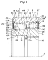
- Fig. 1 is a sectional view showing a one-way clutch unit according to an embodiment of the present invention.
- the one-way clutch unit has a single-row one-way clutch 1 and a single-row ball bearing 2 which are disposed axially adjacent to each other.
- a deep grove ball bearing is used as the ball bearing 2.
- the one-way clutch unit of the embodiment has a one-piece outer ring 3 and a one-piece inner ring 5.
- the one-piece outer ring 3 has a first outer ring part 6 for the one-way clutch 1 and a second outer ring part 7 for the deep groove ball bearing 2 which are integral with each other.
- the one-piece inner ring 5 has a first inner ring part 8 for the one-way clutch 1 and a second inner ring part 10 for the deep groove ball bearing 2 which are integral with each other.
- the one-way clutch 1 has rollers 11 serving as engaging members.
- the first outer ring part 6 of the one-piece outer ring 3 has a cylindrical inner peripheral surface 6A.
- the first inner ring part 8 of the one-piece inner ring 5 has an outer peripheral cam surface 8A decagonal in cross section.
- the one-way clutch 1 and the deep grove ball bearing 2 are lubricated with same grease enclosed between the one-piece outer ring 3 and the one-piece inner ring 5.
- Sealing devices 12 and 13 are disposed between the one-piece outer ring 3 and the one-piece inner ring 5 at both axial ends of the unit to enclose the grease.
- the sealing device 12A has a base portion 12A and a lip portion 12B.
- the base portion 12A which has a core metal is fixed to an annular stepped portion 3B formed on the inner periphery of the one-piece outer ring 3 at one axial end thereof.
- the lip portion 12B of the sealing device 12 is adapted to slide on the peripheral surface of the one-piece inner ring 5 at one axial end thereof.
- the sealing device 13 has a base portion 13A and a lip portion 13B.
- the base portion 13A which has a core metal is fixed to an annular stepped portion 3C formed on the inner periphery of the one-piece outer ring 3 at the other axial end thereof.
- the lip portion 13B of the sealing device 13 is adapted to slide on a stepped portion 5C formed on the peripheral surface of the one-piece inner ring 5 at the other axial end thereof.
- the one-way clutch side and bearing-side sealing devices 12 and 13 can be made to have the same configuration.
- the one-way clutch 1 has a retainer 15 holding the rollers 11, with the rollers 11 fitted in respective pockets 15F of the retainer 15.
- the deep grove ball bearing 2 has a snap cage 17 holding balls 16 serving as rolling elements.
- the one-piece inner ring 5 has a tapered surface 18 between the decagonal peripheral cam surface 8A of the first inner ring part 8 and the inner peripheral surface of the second inner ring part 10.
- the diameter of the tapered surface 18 increases from the side of the one-way clutch 1 to the side the deep grove ball bearing 2.
- An annular portion 17A of the snap cage 17 is disposed on the tapered surface 18 side opposite from the sealing device 13.
- the one-piece outer ring 3 has an annular groove 20 formed at the inner peripheral surface thereof opposed to the tapered surface 18 of the one-piece inner ring 5.
- the annular groove 20 serves as a grease reservoir.
- the number of the rollers 11 is ten, which is equal to the number of cam surfaces constituting the sectionally decagonal peripheral cam surface 8A.
- the number of the balls 16 of the ball bearing 2 is 15, which is more than that of the rollers 11.
- the axial length of the one-piece inner ring 5 is longer than that of the one-piece outer ring 3, and an end 5D of the one-piece inner ring 5 at the side of the one-way clutch 1 projects axially by a predetermined dimension beyond a corresponding end 3D of the one-piece outer ring 3.
- the second inner ring part 10 of the one-piece inner ring 5 has its inner periphery threaded to accomplish sufficient transmission of the driving force while making the one-way clutch unit axially compact.
- the one-piece outer ring 3 has a thickness smaller than that of the one-piece inner ring 5, whereby the raceway diameters for the rollers 11 and the balls 16 can be increased to thereby improve the withstand load, or load capacity.
- the one-piece inner ring 5 has an annular groove 21 at the outer peripheral surface of the first inner ring part 8 on a side opposite from the ball bearing.
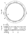
- An annular portion 15A of the retainer 15 opposite from the bearing (“the counter-bearing-side retainer 15A") has a projection 22 projecting radially inward (see Figs. 2A and 2B). By fitting the projection 22 in the annular groove 21, the retainer 15 is axially locked to the first inner ring part 8.
- the retainer 15 has a decagonal inner peripheral surface portion 23 that fits on the decagonal outer peripheral cam surface 8A of the first inner ring part 8.
- a bearing-side axial end of the inner peripheral surface 15B-1 of the annular portion 15B forms a tapered surface 25 widening as moving radially outwardly.
- the projection 22 formed radially inside of the counter-bearing-side annular portion 15A of the retainer 15 has an axially inside surface that defines a tapered surface 22A, which has an increasing diameter as moving axially inwardly. Owing to the presence of the tapered surface 22A, the retainer 15 can be inserted easily axially along the peripheral cam surface 8A of the first inner ring part 8 of the one-piece inner ring 5. Thus the retainer 15 can be easily mounted on the one-piece inner ring 5.
- a stepped portion 26 is formed at the peripheral edge of a radially outward end surface 15A-1 of the counter-bearing-side annular portion 15A. As shown in Fig. 1, the stepped portion 26 serves to store the grease between the stepped portion 26 and the sealing device 12.
- the radius of curvature of a raceway surface 27 of the second outer ring part 7 for the deep groove ball bearing 2 and that of a raceway surface 28 of the second inner ring part 10 therefor are set to values in the range of 50.5% to 51.5% of the diameter of the balls 16 respectively.
- the axial length of the rollers 11 of the one-way clutch 1 is set to a value in a range of from one to two times as large as a diameter of the rollers 11.
- the radial gap of the deep groove ball bearing 2 is set to a value in a range of from 0 ⁇ m to 20 ⁇ m when the one-piece outer ring 3 is press-fitted in a bore of a housing (not shown) in which the one-way clutch unit is incorporated.
- the first outer ring part 6 for the one-way clutch 1 and the second outer ring part 7 for the deep groove ball bearing 2 are united or integrated into the one-piece outer ring 3.
- the first inner ring part 8 for the one-way clutch 1 and the second inner ring part 10 for the deep groove ball bearing 2 are integrated into the one-piece inner ring 5.
- the annular portion 17A of the snap cage 17 is disposed in a space between the tapered surface 18 (which is present between the decagonal outer peripheral cam surface 8A of the first inner ring part 8 and the peripheral surface of the second inner ring part 10) and the opposite inner peripheral surface of the one-piece outer ring 3.
- Such effective utilization of a space prevents an increase of an axial dimension that would be otherwise caused by the provision of the snap cage 17. In other words, it is possible to reduce the axial dimension.
- the annular portion 17A of the snap cage 17 is disposed on the clutch side, a space on the sealing device 13 side increases. Therefore it is possible to enhance circulation of the grease and hence reduce the pressure of the grease. As a result, compared with a case where the annular portion 17A is disposed on the sealing device 13 side, it is possible to prevent leak of the grease to a higher extent.
- the tapered surface 18 can be formed by preparing the decagonal outer peripheral cam surface 8A of the first inner ring part 8 of the one-piece inner ring 5 by cold forging.
- the stepped portion 26 serving as the grease reservoir is formed on the counter-bearing-side annular portion 15A of the retainer 15, storage of grease is facilitated.
- the pressure of the grease is reduced so that leak of the grease is prevented. Further it is possible to increase a grease-storing capacity and improve the grease life.
- the annular groove 20 serving as the grease reservoir is also formed at the inner peripheral surface of the one-piece outer ring 3, the grease-storing capacity is increased. Thus an increased volume of grease can be loaded and the life of the grease can be improved. Because the annular portion 20 is formed in a region confronting the tapered surface 18, a grease reservoir is provided with good space utilization efficiency.
- the axial length of the one-piece inner ring 5 is longer than that of the one-piece outer ring 3 and at the same time the end 5D of the one-piece inner ring 5 at the side of the one-way clutch 1 projects axially by a predetermined dimension beyond the corresponding end 3D of the one-piece outer ring 3.
- the retainer 15 for the one-way clutch is axially locked to the one-piece inner ring 5.
- the retainer 15 for the clutch has the decagonal inner peripheral surface portion 23. Fitting the decagonal inner peripheral surface portion 23 onto the decagonal outer peripheral cam surface 8A of the first inner ring part 8 achieves the function of locking the retainer 15 against rotation. Therefore it is unnecessary to use additional component parts for that purpose, which makes it possible to make the unit compact.
- the tapered surface 25 at the bearing-side axial end of the retainer 15, which widens as it goes axially outwardly, serves as a guide surface for guiding the retainer 15 along the decagonal peripheral cam surface 8A of the first inner ring part 8 of the one-piece inner ring 5.
- the retainer 15 can be easily mounted around the one-piece inner ring 5.
- the radii of curvature of the raceway surface 27 of the second outer ring part 7 and of the raceway surface 28 of the second inner ring part 10 for the deep groove ball bearing 2 are each set to a value in the range of 50.5% to 51.5% of the diameter of the ball 16, reduction in the inclination of the one-piece outer ring 3 with respect to the rotational axis J is accomplished, and the engagement performance in the one-way clutch 1 and its durability can be improved.
- the axial length of the rollers 11 of the one-way clutch 1 is set to a value in a range of from one to two times as large as the diameter of the rollers, it is possible to restrain a difference in the distance of the inner peripheral surface 6A of the first outer ring part 6 from the outer peripheral cam surface 8A of the first inner ring part 8 between at both axial ends of the rollers 11, which would occur when the one-piece outer ring is inclined.
- the engagement performance in the one-way clutch 1 and its durability can be improved.
- the radial gap of the deep groove ball bearing 2 when the one-piece outer ring 3 is press-fitted in an unshown housing is set to a value in the range of 0 ⁇ m to 20 ⁇ m, inclination of the one-piece outer ring 3 with respect to the rotational axis J of the one-piece inner ring 5 is suppressed.
- the engagement performance and durability of the one-way are improved.
- the peripheral surface of the first inner ring part 8 of the one-piece inner ring 5 is decagonal.
- the peripheral surface thereof may have a shape of a polygon other than a decagon.
- the inner peripheral surface portion 23 of the retainer 15 for the clutch is formed in a polygonal shape corresponding to the polygonal shape of the peripheral surface of the first inner ring part 8.
Landscapes
- Engineering & Computer Science (AREA)
- General Engineering & Computer Science (AREA)
- Mechanical Engineering (AREA)
- Rolling Contact Bearings (AREA)
- Mechanical Operated Clutches (AREA)
- Structure Of Transmissions (AREA)
Applications Claiming Priority (2)
| Application Number | Priority Date | Filing Date | Title |
|---|---|---|---|
| JP2001213644A JP2003028201A (ja) | 2001-07-13 | 2001-07-13 | 一方向クラッチユニット |
| JP2001213644 | 2001-07-13 |
Publications (2)
| Publication Number | Publication Date |
|---|---|
| EP1275868A1 true EP1275868A1 (de) | 2003-01-15 |
| EP1275868B1 EP1275868B1 (de) | 2004-11-10 |
Family
ID=19048582
Family Applications (1)
| Application Number | Title | Priority Date | Filing Date |
|---|---|---|---|
| EP02015417A Expired - Lifetime EP1275868B1 (de) | 2001-07-13 | 2002-07-11 | Einwegkupplungseinheit |
Country Status (7)
| Country | Link |
|---|---|
| US (1) | US6705444B2 (de) |
| EP (1) | EP1275868B1 (de) |
| JP (1) | JP2003028201A (de) |
| KR (1) | KR100502738B1 (de) |
| CN (1) | CN1271352C (de) |
| BR (1) | BR0202687A (de) |
| DE (1) | DE60201866T2 (de) |
Families Citing this family (15)
| Publication number | Priority date | Publication date | Assignee | Title |
|---|---|---|---|---|
| JP2003106253A (ja) * | 2001-09-27 | 2003-04-09 | Toyota Industries Corp | 圧縮機 |
| US20070267529A1 (en) * | 2006-04-12 | 2007-11-22 | Pure Fishing, Inc. | Clutch Assembly For A Fishing Reel |
| JP5057209B2 (ja) * | 2006-12-27 | 2012-10-24 | 株式会社ジェイテクト | 一方向クラッチユニット |
| EP1939479B1 (de) | 2006-09-28 | 2012-07-11 | JTEKT Corporation | Freilaufkupplung mit Drehmomentbegrenzer |
| US7703746B2 (en) * | 2007-07-12 | 2010-04-27 | Roller Bearing Company Of America, Inc. | Ground-based power generator with ball-roller bearing butterfly valve |
| DE102008037995A1 (de) * | 2008-08-16 | 2010-02-18 | Schaeffler Kg | Klemmrollen-Freilauf |
| CN102187109B (zh) * | 2008-09-15 | 2013-09-04 | 麦格纳动力系有限公司 | 用于发动机起动系统的具有密封单向离合器的转矩传递单元 |
| CA2737063A1 (en) * | 2008-09-15 | 2010-03-18 | Magna Powertrain Inc. | Sealed high capacity overrunning roller clutch |
| US9097296B2 (en) * | 2008-09-15 | 2015-08-04 | MagnaPowertrain, Inc. | Sealed one way roller clutch |
| KR101371146B1 (ko) * | 2009-11-19 | 2014-03-05 | 마그나 파워트레인 인크. | 엔진 시동 시스템용 진동 댐퍼를 가지는 단방향 클러치 |
| WO2012024660A2 (en) * | 2010-08-20 | 2012-02-23 | Seektech, Inc. | Asymmetric drag force bearings for use with push-cable storage drums |
| JP2012106560A (ja) * | 2010-11-16 | 2012-06-07 | Jtekt Corp | 電動パワーステアリング装置 |
| US9367688B2 (en) | 2012-06-22 | 2016-06-14 | Intel Corporation | Providing geographic protection to a system |
| CN103697086A (zh) * | 2013-12-27 | 2014-04-02 | 常州国源离合器有限公司 | 一种带轴承支撑的新型外星轮单向离合器 |
| KR101672650B1 (ko) * | 2015-09-09 | 2016-11-04 | 지상훈 | 양방향 회전이 가능한 원웨이 클러치 |
Citations (5)
| Publication number | Priority date | Publication date | Assignee | Title |
|---|---|---|---|---|
| DE4421161A1 (de) * | 1994-06-20 | 1995-12-21 | Schaeffler Waelzlager Kg | Wälzgelagerter Klemmrollenfreilauf mit Dichtung |
| DE19531745A1 (de) * | 1994-08-30 | 1996-03-07 | Ntn Toyo Bearing Co Ltd | Riemenscheiben-Baueinheit |
| WO1996033354A1 (de) * | 1995-04-19 | 1996-10-24 | Ina Wälzlager Schaeffler Kg | Klemmrollenfreilauf |
| JPH11218144A (ja) * | 1997-11-17 | 1999-08-10 | Nippon Seiko Kk | ワンウェイクラッチ内蔵転がり軸受 |
| DE19920508A1 (de) * | 1999-05-05 | 2000-11-09 | Schaeffler Waelzlager Ohg | Schaltbare Kupplung |
Family Cites Families (10)
| Publication number | Priority date | Publication date | Assignee | Title |
|---|---|---|---|---|
| US3623581A (en) * | 1970-09-14 | 1971-11-30 | William G Livezey | Overrunning device |
| JPH0772568B2 (ja) * | 1987-05-02 | 1995-08-02 | アイシン・エィ・ダブリュ株式会社 | 自動変速機 |
| JPH02309021A (ja) | 1989-05-19 | 1990-12-25 | Ntn Corp | ワンウェイクラッチ・軸受の一体組立構造体 |
| JPH0623579B2 (ja) | 1989-06-30 | 1994-03-30 | エヌエスケー・ワーナー株式会社 | ワンウエイクラッチ |
| DE4219154C2 (de) * | 1992-06-11 | 1995-04-20 | Ford Werke Ag | Rollen- oder Klemmkörper-Freilauf mit seitlicher zusätzlicher Wälzlagerung |
| US5433305A (en) * | 1992-09-04 | 1995-07-18 | Koyo Seiko Co., Ltd. | Overrunning clutch and a rolling bearing united in a casing |
| US5601166A (en) * | 1995-09-06 | 1997-02-11 | Ntn Corporation | Aligning type roller clutch |
| JP3604489B2 (ja) | 1996-02-22 | 2004-12-22 | 光洋精工株式会社 | 軸受装置およびそれを備える補機駆動用プーリ装置 |
| JP4111556B2 (ja) | 1996-04-24 | 2008-07-02 | 株式会社ジェイテクト | エンジンの補機用高速回転プーリユニット |
| JP2000291651A (ja) | 1999-04-12 | 2000-10-20 | Koyo Seiko Co Ltd | 一方向クラッチ付き転がり軸受 |
-
2001
- 2001-07-13 JP JP2001213644A patent/JP2003028201A/ja active Pending
-
2002
- 2002-07-11 KR KR10-2002-0040226A patent/KR100502738B1/ko not_active Expired - Fee Related
- 2002-07-11 EP EP02015417A patent/EP1275868B1/de not_active Expired - Lifetime
- 2002-07-11 DE DE60201866T patent/DE60201866T2/de not_active Expired - Fee Related
- 2002-07-12 BR BR0202687-2A patent/BR0202687A/pt not_active IP Right Cessation
- 2002-07-12 US US10/193,227 patent/US6705444B2/en not_active Expired - Fee Related
- 2002-07-13 CN CNB021425701A patent/CN1271352C/zh not_active Expired - Fee Related
Patent Citations (5)
| Publication number | Priority date | Publication date | Assignee | Title |
|---|---|---|---|---|
| DE4421161A1 (de) * | 1994-06-20 | 1995-12-21 | Schaeffler Waelzlager Kg | Wälzgelagerter Klemmrollenfreilauf mit Dichtung |
| DE19531745A1 (de) * | 1994-08-30 | 1996-03-07 | Ntn Toyo Bearing Co Ltd | Riemenscheiben-Baueinheit |
| WO1996033354A1 (de) * | 1995-04-19 | 1996-10-24 | Ina Wälzlager Schaeffler Kg | Klemmrollenfreilauf |
| JPH11218144A (ja) * | 1997-11-17 | 1999-08-10 | Nippon Seiko Kk | ワンウェイクラッチ内蔵転がり軸受 |
| DE19920508A1 (de) * | 1999-05-05 | 2000-11-09 | Schaeffler Waelzlager Ohg | Schaltbare Kupplung |
Also Published As
| Publication number | Publication date |
|---|---|
| KR20030007115A (ko) | 2003-01-23 |
| DE60201866D1 (de) | 2004-12-16 |
| US20030010591A1 (en) | 2003-01-16 |
| US6705444B2 (en) | 2004-03-16 |
| KR100502738B1 (ko) | 2005-07-20 |
| JP2003028201A (ja) | 2003-01-29 |
| CN1271352C (zh) | 2006-08-23 |
| DE60201866T2 (de) | 2005-10-27 |
| BR0202687A (pt) | 2003-06-03 |
| EP1275868B1 (de) | 2004-11-10 |
| CN1401919A (zh) | 2003-03-12 |
Similar Documents
| Publication | Publication Date | Title |
|---|---|---|
| EP1275868B1 (de) | Einwegkupplungseinheit | |
| US20050087417A1 (en) | Engine start roller clutch-housed type rotation transmission device | |
| US20020148697A1 (en) | One-way clutch assembly | |
| US8613352B2 (en) | One-way clutch retainer | |
| EP1217259A1 (de) | Riemenscheibeneinheit | |
| EP2886900A1 (de) | Rollenkupplung mit stützlager | |
| JP2008180246A (ja) | 円すいころ軸受 | |
| US6749050B2 (en) | One-way clutch built-in type pulley device | |
| EP1262686A2 (de) | Riemenscheibe mit Einwegkupplung | |
| EP3051160A1 (de) | Rillenkugellager | |
| JP2000320558A (ja) | ころ軸受用合成樹脂製保持器 | |
| EP2985488A1 (de) | Einwegkupplungsvorrichtung | |
| JP2001349413A (ja) | ローラクラッチ内蔵型プーリ装置 | |
| US6739441B2 (en) | Ratchet one-way clutch and stator using ratchet one-way clutch | |
| JP2021139455A (ja) | ケージアンドローラ | |
| JPH10318264A (ja) | ころ軸受用合成樹脂製保持器 | |
| JP2002188709A (ja) | プーリユニット | |
| US6749051B2 (en) | Ratchet one-way clutch and stator using ratchet one-way clutch | |
| US5355982A (en) | Starter drive for internal combustion engines | |
| JPH1172127A (ja) | ワンウェイクラッチ内蔵転がり軸受 | |
| JP2005098415A (ja) | 斜板式圧縮機用のスラストころ軸受 | |
| JP2005214312A (ja) | スラストころ軸受付一方向クラッチ組立体 | |
| KR102029662B1 (ko) | 레이디얼 볼 베어링용 케이지 | |
| JP2006307922A (ja) | 一方向クラッチ | |
| JP2008196543A (ja) | 円すいころ軸受 |
Legal Events
| Date | Code | Title | Description |
|---|---|---|---|
| PUAI | Public reference made under article 153(3) epc to a published international application that has entered the european phase |
Free format text: ORIGINAL CODE: 0009012 |
|
| 17P | Request for examination filed |
Effective date: 20020711 |
|
| AK | Designated contracting states |
Kind code of ref document: A1 Designated state(s): AT BE BG CH CY CZ DE DK EE ES FI FR GB GR IE IT LI LU MC NL PT SE SK TR |
|
| AX | Request for extension of the european patent |
Free format text: AL;LT;LV;MK;RO;SI |
|
| AKX | Designation fees paid |
Designated state(s): DE FR IT |
|
| 17Q | First examination report despatched |
Effective date: 20031020 |
|
| GRAP | Despatch of communication of intention to grant a patent |
Free format text: ORIGINAL CODE: EPIDOSNIGR1 |
|
| GRAS | Grant fee paid |
Free format text: ORIGINAL CODE: EPIDOSNIGR3 |
|
| GRAA | (expected) grant |
Free format text: ORIGINAL CODE: 0009210 |
|
| AK | Designated contracting states |
Kind code of ref document: B1 Designated state(s): DE FR IT |
|
| REG | Reference to a national code |
Ref country code: IE Ref legal event code: FG4D |
|
| REF | Corresponds to: |
Ref document number: 60201866 Country of ref document: DE Date of ref document: 20041216 Kind code of ref document: P |
|
| PLBE | No opposition filed within time limit |
Free format text: ORIGINAL CODE: 0009261 |
|
| STAA | Information on the status of an ep patent application or granted ep patent |
Free format text: STATUS: NO OPPOSITION FILED WITHIN TIME LIMIT |
|
| ET | Fr: translation filed | ||
| 26N | No opposition filed |
Effective date: 20050811 |
|
| PGFP | Annual fee paid to national office [announced via postgrant information from national office to epo] |
Ref country code: DE Payment date: 20070705 Year of fee payment: 6 |
|
| PGFP | Annual fee paid to national office [announced via postgrant information from national office to epo] |
Ref country code: IT Payment date: 20070727 Year of fee payment: 6 |
|
| PGFP | Annual fee paid to national office [announced via postgrant information from national office to epo] |
Ref country code: FR Payment date: 20070710 Year of fee payment: 6 |
|
| PG25 | Lapsed in a contracting state [announced via postgrant information from national office to epo] |
Ref country code: DE Free format text: LAPSE BECAUSE OF NON-PAYMENT OF DUE FEES Effective date: 20090203 |
|
| REG | Reference to a national code |
Ref country code: FR Ref legal event code: ST Effective date: 20090331 |
|
| PG25 | Lapsed in a contracting state [announced via postgrant information from national office to epo] |
Ref country code: IT Free format text: LAPSE BECAUSE OF NON-PAYMENT OF DUE FEES Effective date: 20080711 Ref country code: FR Free format text: LAPSE BECAUSE OF NON-PAYMENT OF DUE FEES Effective date: 20080731 |