EP1275615A2 - Appareils de fixation, à chaíne, pour le capitonnage de coussins - Google Patents
Appareils de fixation, à chaíne, pour le capitonnage de coussins Download PDFInfo
- Publication number
- EP1275615A2 EP1275615A2 EP02022086A EP02022086A EP1275615A2 EP 1275615 A2 EP1275615 A2 EP 1275615A2 EP 02022086 A EP02022086 A EP 02022086A EP 02022086 A EP02022086 A EP 02022086A EP 1275615 A2 EP1275615 A2 EP 1275615A2
- Authority
- EP
- European Patent Office
- Prior art keywords
- tuft
- mattress
- needle
- tufting
- tufts
- Prior art date
- Legal status (The legal status is an assumption and is not a legal conclusion. Google has not performed a legal analysis and makes no representation as to the accuracy of the status listed.)
- Granted
Links
- 239000000463 material Substances 0.000 claims abstract description 9
- 238000009732 tufting Methods 0.000 description 41
- 238000000034 method Methods 0.000 description 20
- 230000006835 compression Effects 0.000 description 9
- 238000007906 compression Methods 0.000 description 9
- -1 polyethylene Polymers 0.000 description 4
- 230000007246 mechanism Effects 0.000 description 3
- 239000004677 Nylon Substances 0.000 description 2
- 239000004698 Polyethylene Substances 0.000 description 2
- 239000004743 Polypropylene Substances 0.000 description 2
- 239000002184 metal Substances 0.000 description 2
- 229920001778 nylon Polymers 0.000 description 2
- 229920000573 polyethylene Polymers 0.000 description 2
- 229920001155 polypropylene Polymers 0.000 description 2
- 229920000297 Rayon Polymers 0.000 description 1
- 239000011111 cardboard Substances 0.000 description 1
- 238000010276 construction Methods 0.000 description 1
- 230000001627 detrimental effect Effects 0.000 description 1
- 238000005516 engineering process Methods 0.000 description 1
- 239000006260 foam Substances 0.000 description 1
- 239000010985 leather Substances 0.000 description 1
- 238000000465 moulding Methods 0.000 description 1
- 239000004033 plastic Substances 0.000 description 1
- 229920003023 plastic Polymers 0.000 description 1
- 229920000642 polymer Polymers 0.000 description 1
- 239000002964 rayon Substances 0.000 description 1
- 239000002023 wood Substances 0.000 description 1
Images


Classifications
-
- B—PERFORMING OPERATIONS; TRANSPORTING
- B68—SADDLERY; UPHOLSTERY
- B68G—METHODS, EQUIPMENT, OR MACHINES FOR USE IN UPHOLSTERING; UPHOLSTERY NOT OTHERWISE PROVIDED FOR
- B68G7/00—Making upholstery
- B68G7/08—Quilting; Elements therefor
-
- B—PERFORMING OPERATIONS; TRANSPORTING
- B68—SADDLERY; UPHOLSTERY
- B68G—METHODS, EQUIPMENT, OR MACHINES FOR USE IN UPHOLSTERING; UPHOLSTERY NOT OTHERWISE PROVIDED FOR
- B68G15/00—Auxiliary devices and tools specially for upholstery
- B68G15/005—Worktables or workframes
-
- D—TEXTILES; PAPER
- D10—INDEXING SCHEME ASSOCIATED WITH SUBLASSES OF SECTION D, RELATING TO TEXTILES
- D10B—INDEXING SCHEME ASSOCIATED WITH SUBLASSES OF SECTION D, RELATING TO TEXTILES
- D10B2505/00—Industrial
- D10B2505/08—Upholstery, mattresses
Definitions
- This invention relates to an improved method for the automatic tufting of mattresses, futons, cushions and the like.
- the invention also relates to a device for carrying out the method.
- the tuft also serves to stabilise the outer layers of materials, tickings and fillings.
- the word 'tuft' is generally understood to comprise two elements (hereinafter known as 'tuft elements') located outside each principal face of the mattress, and held together by means of a cord, strip or similar device (hereinafter referred to as a 'retaining link'), attached to each tuft element.
- 'tuft elements' two elements located outside each principal face of the mattress, and held together by means of a cord, strip or similar device (hereinafter referred to as a 'retaining link'), attached to each tuft element.
- a 'retaining link' a cord, strip or similar device
- tuft One particular type of tuft known in the art is the "tape tuft" 22 illustrated in Fig. 1.
- This tuft comprises a strip 12 of flexible material (typically nylon, although polyethylene, polypropylene, rayon and other materials may also be used) which interacts at either end with tuft elements 14a, 14b of harder material (polymers such as nylon, polyethylene and polypropylene being preferred, although other materials such as metal and wood may also be used), the longitudinal axis of the strip being substantially perpendicular to the longitudinal axis of the tuft elements.
- a tape tuft is described and illustrated in GB-A-2349332. Similar tufts are described in, for example, GB 814651, although the tuft elements described in this patent are made of different material.
- An alternative form of tape tuft is described in pending GB application no. 0105081.4.
- Tape tufts may advantageously be produced by moulding. As illustrated in Fig. 1, a string 10 of tufts 22, 24, 26 joined in series and comprising a continuous strip 12 interacting with tuft elements 14a, 14b, 14c, 14d, 14e, may be produced.
- the string of tufts may typically be provided on a reel or the like: the tufts are separated by cutting the strip between the tuft elements. Alternatively, the string could be supplied pre-cut into individual tufts which are then loaded into a magazine or the like.
- such tape tufts are attached to the mattress using a needle, such as a tufting or ejector needle, the structure of which is well known to those skilled in the art.
- a needle such as a tufting or ejector needle
- An example of a tufting needle is given in GB 903464, the contents of which are incorporated herein by reference thereto.
- the mattress is first compressed to a thickness less than the length of the tape tuft to be used.
- One of the tuft elements is inserted into a recess in the tufting needle, leaving the other end free.
- the tufting needle, carrying the first tuft element is then passed through both faces of the mattress, the second (free) tuft element being unable to pass through the hole made by the needle and consequently remaining outside the mattress.
- the tufting needle exits the mattress the first tuft element is released so that both tuft elements are located on the outside faces of the mattress.
- the tufting needle may further be provided with elastic means, such as a spring-loaded plunger, which ejects or otherwise aids release of the first tuft element from the tufting needle.
- a support such as a washer
- a support may be provided on either or both faces of the mattress.
- the function of such supports is to prevent the tuft element from being pulled through the mattress ticking and to make the tuft more comfortable to sit or lie on.
- Such supports may be made from felt, cardboard, foam, leather or plastic: an alternative form of support is described in pending GB application no. 0105082.2.
- a first washer may be fitted to the proximal face of the mattress (ie the face the needle enters) by attaching it to the free tuft element, the washer being unable to pass through the mattress.
- the needle When the needle emerges from the distal face of the mattress, its point may engage a second washer so that when the first tuft element is released from the tufting needle, the washer need only be disengaged from the needle point to be in the correct position.
- the second washer may be placed on the tuft element after it has been ejected from the tufting needle, before the mattress is decompressed.
- the tufting method described hereinabove has traditionally been carried out manually.
- the operator may have to apply a considerable amount of force to drive the tufting needle through the mattress. This makes the process slow and inefficient, and repeatedly applying such forces over a long period of time may be detrimental to the health of the operator.
- Machines which allow the tufting needle to engage with driving means such as a pneumatic piston or mechanical jack, are known in the art.
- driving means such as a pneumatic piston or mechanical jack.
- the first tuft element is engaged with a recess on the tufting needle as described hereinabove, and the needle is then connected to, or forms part of, means which drive the needle through the mattress.
- An example of such a machine is described in GB 910253.
- EP-A-844210 which is believed to represent the closest state of the art, describes and illustrates a tufting machine including a plurality of devices, such as tufting needles, capable of receiving a tuft element and which can be positioned on a mattress at the point where the tuft is to be applied, and actuator means for pushing the tufting devices through the mattress.
- the tuft elements must be loaded manually into the tufting devices of this machine.
- the present invention seeks to solve the problem of providing a tufting machine and method which minimises manual input, and, in particular, avoid the need to load the tuft element manually.
- the present invention seeks to provide a device capable of tufting a mattress using the string of tufts described above, without the operator having to stop the device after fitting a tuft to separate the next tuft from the string.
- the present invention aims to provide a tufting machine capable of aiding the release of the tuft element from the tufting needle.
- the present invention seeks to solve the problem of providing a tufting machine capable of automatically placing supports (such as washers) in their correct positions.
- a device for the automatic tufting of upholstery units using tufts comprising a retaining link with a tuft element at either end, said device including:
- the device may further include means for aiding the release of the engaged tuft from the engagement means.
- the device may also comprise means for engaging and correctly placing in its supporting position at least one support (such as a washer).
- at least one support such as a washer
- such means could take the form of feed means arranged for cooperation with the automatic tufting device.
- the tuft used in the device and method according to the present invention is supplied from a plurality of associated tufts. It is preferred that the tuft is connected in a string of tufts, as described and illustrated below. In this case, the tuft may advantageously be separated from the string by cutting; for example, by means of one or more appropriately positioned blades. However, the tuft may also be associated with individual pre-cut tufts in a magazine or the like, the storage and loading of such tufts being readily apparent to those skilled in the art.
- the upholstery unit is preferably compressed throughout the process.
- heavy bars may be provided all the way across each face of the mattress, said bars capable of moving towards one another to compress the entire upholstery unit during the process and away from one another to release the upholstery unit at the end of the process.
- local compression may be applied by the application of pressure to the surface of the upholstery unit in the specific area where the engagement means is to act upon.
- a light mesh typically of metal
- Pressure is applied preferably by an element of annular construction.
- the engagement means comprises a tufting needle
- the needle with the engaged tuft element and, optionally, support can easily pass through the hole and the point of compression is centred on the needle.
- the method may further include the step of aiding the release of the engaged tuft from the engagement means.
- the device includes means for engaging a tuft, preferably by engaging one of the tuft elements.
- the means for engaging a tuft preferably comprises an ejector or tufting needle as is well known to those skilled in the art, one tuft element advantageously being inserted into a recess in such a tufting needle.
- the engagement means may further be provided with means for ejecting or otherwise aiding release of the tuft element from the tufting needle.
- the ejection means may preferably comprise elastic means such as a spring-loaded plunger, the spring being weaker than the breaking strength of the tuft. As the engagement means moves through the upholstery unit, it is the plunger which acts upon the tuft element, taking it through the upholstery unit.
- the force against the plunger may be resisted by the action of a spring.
- the retaining link becomes taut; as the engagement means continues to advance, increasing pressure becomes applied to the plunger unit. In turn this increases the force on the spring such that at a load below the breaking strength of the tuft element, the load on the spring is overcome and the plunger moves rearwards relative to the body of the engagement means. This allows the tuft element to be released from the engagement means.
- driving means such as a pneumatic piston, mechanical jack or any other suitable means may be used to move or release the plunger at the appropriate position to release the tuft element at the correct location.
- the location of the tuft element in the engagement means may also be such that the action of the plunger is in the reverse sense such that the tuft element is ejected from the engagement means by the plunger pushing the tuft element from the engagement means.
- the engagement means may be connected to, or form part of, means for driving the engaged tuft element through the upholstery unit.
- the driving means may comprise, for example, a pneumatic piston or mechanical jack, although any means suitable for driving the tuft element through the upholstery unit may be used in the device and method according to the present invention.
- the device may be supported on any mechanical support means known in the art, for example, a supporting plate or other similar structure.
- the device may be adapted to be hand-held. It should however be noted that in such a case the device according to the present invention remains mechanically powered and operated, the operator merely holding the device in the correct position.
- a single device may be provided, the device being movable so that all sides of the upholstery unit may be tufted.
- multiple devices under common control may be provided so that several sections of the upholstery unit may be tufted at once.
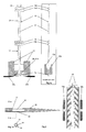
- Fig. 1 shows generally the tape tuft string 10 comprising retaining link 12, which is held under constant tension and interacts with tuft elements 14a, 14b, 14c, 14d, 14e.
- the string 10 passes through jaws 18a and 18b which are mounted on a sliding guide 16.
- the two jaws 18a and 18b operate such that they will spring open over the tuft elements 14b, 14c when drawn back up the string of tufting tapes and snap shut in a non return action.
- Two blades 20a, 20b are provided for cutting the tape and thereby separating it from the string.
- the tuft element 14a is positioned over a tufting needle 30 comprising plunger 32, recess 34 and outer tube 36.
- Fig. 1 also shows washers 38a and 38b located either side of the mattress 40, shown in section.
- the mattress 40 is in compression.
- the principal components are in place to insert the first tuft element 14a into the needle 30.
- Fig. 1a is a side view of the components 10, 12, 14, 16 and 18 in Fig. 1, and illustrates retaining link 12 held between jaws 18a and 18b, tuft element 14a being outside the jaws.
- Fig. 1b is a section along the line A-A of Fig. 1, and illustrates recess 34 cut out of the outer tube 36 of tufting needle 30.
- Fig. 2 shows the jaws 18 having moved forward, drawing the string of tape tufts 10 with them and positioned such that tuft element 14a is engaged in recess 34.
- Fig. 3 shows the needle tube 36 having moved backwards with the plunger 32 remaining in place. This locks tuft element 14a in recess 34.
- Fig. 4 shows the jaws 18 having moved back past its start position up the string 10 to an intermediate position between tuft elements 14c and 14d.
- Fig. 5 shows the jaws 18 returning to the start position. Note that tuft elements 14b, 14c are in front of the start position of jaws 18.
- Fig. 6 shows the entire assembly of items 16, 18 and 20 having moved forward to provide slack in the first tape tuft 22 between tuft elements 14a and 14b.
- Fig. 7 shows the blades 20 having cut the first tape tuft 22 off the string 10 of tape tufts in between tuft elements 14b and 14c.
- the first tuft 22 is held in the needle 30.
- Fig. 8 shows the assembly 16, 18 and 20 having moved back to the start position. It also shows needle 30 and first tape tuft 22 entering mattress 40 having first passed through the washer 38a on the proximal side of mattress 40.
- Fig. 9 shows needle 30 and tape tuft 22 passing through distal washer 38b.
- Figs. 9 and 10 shows needle and tape tuft 22 emerging through mattress 40, having pulled the proximal washer 38a free from a unit which feeds the washers (the feed unit being shown in Fig. 15).
- Fig. 11 shows needle 30 starting to apply tension to tape tuft 22 as it continues to advance.
- Fig. 12 shows the tuft element 14a being ejected from needle 30 by the rearward movement of plunger 32 relative to the outer tube 36 of the needle 30. This may be assisted by having a spring (not shown) behind plunger 32, which is compressed by the tape 22 becoming taut as needle 30 continues to move forward. Alternatively, plunger 32 may be mechanically drawn backwards by any suitable means known in the art.
- Fig. 13 shows needle 30 withdrawing from mattress 40 leaving the tape tuft 22 with washers 38a, 38b threaded on each end between tuft elements 14a, 14b and the surface of the mattress 40.
- Fig. 14 shows a section of the mattress 40 uncompressed with the tape tuft 22 and washers 38 in place.
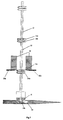
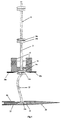
- Fig. 15 shows a possible layout of the unit with the mattress 40 having been compressed by bars 42 and some tape tufts 22 and washers 38 having already been inserted.
- the tape tuft string 10 is shown running from a reel 44 over a tensioning device 46 in to the insert and cutting device 48 (comprising, amongst other operating mechanisms, of guide 16, jaws 18 and blades 20), the needle unit mounted on mechanism 50, the washer and needle 52 with the washer feed 54 all mounted on plate 56.
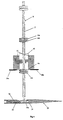
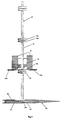
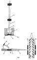
- Figs. 16 to 18 illustrate an alternative embodiment of the invention, in which local compression is applied.
- Fig. 16 shows the starting position of ring 58 between mattress 40 and washer 38a.
- Fig. 17 shows the local compression action of ring 58 and the position of the needle 30 and washer 38a, corresponding to the position between Figs. 7 and 8.
- Fig. 18 shows the continuing action of the needle 30 and associated elements. Further steps correspond to those in Figs. 9 to 14.
- these units may move in a pre-programmed X and Y axis utilising known technology. These units may also be mounted on both sides of the machine. Alternatively, the units may be mounted on the end of a robot arm. Not shown, but of a simple feeding mechanism, are the washer feeds for the second washers.
- the mattress would be inserted either manually or automatically in to the compression machine and once in place, the machine starts.
- the first action would be to compress the mattress.
- the tufting units would then proceed to move and tuft in a programmed fashion until all the tufts are in place.
- the machine would then decompress and eject the mattress.
Landscapes
- Engineering & Computer Science (AREA)
- Mechanical Engineering (AREA)
- Manufacturing & Machinery (AREA)
- Sewing Machines And Sewing (AREA)
- Mattresses And Other Support Structures For Chairs And Beds (AREA)
- Load-Engaging Elements For Cranes (AREA)
- Circuits Of Receivers In General (AREA)
- Chairs For Special Purposes, Such As Reclining Chairs (AREA)
- Massaging Devices (AREA)
- Farming Of Fish And Shellfish (AREA)
- Radio Relay Systems (AREA)
- Yarns And Mechanical Finishing Of Yarns Or Ropes (AREA)
- Outerwear In General, And Traditional Japanese Garments (AREA)
- Ropes Or Cables (AREA)
- Hinges (AREA)
- Automatic Embroidering For Embroidered Or Tufted Products (AREA)
- Bedding Items (AREA)
Applications Claiming Priority (5)
| Application Number | Priority Date | Filing Date | Title |
|---|---|---|---|
| GB0015139A GB2363803B (en) | 2000-06-20 | 2000-06-20 | Device and method for automatically tufting upholstery |
| GB0015139 | 2000-06-20 | ||
| EP01305367A EP1167279B1 (fr) | 2000-06-20 | 2001-06-20 | Dispositif et procédé pour tufter automatiquement des matelassures |
| CA002366126A CA2366126C (fr) | 2000-06-20 | 2001-12-21 | Dispositif et methode de capitonnage automatique d'articles rembourres |
| US10/024,390 US6718894B2 (en) | 2000-06-20 | 2001-12-21 | Device and method for automatically tufting upholstery |
Related Parent Applications (1)
| Application Number | Title | Priority Date | Filing Date |
|---|---|---|---|
| EP01305367A Division EP1167279B1 (fr) | 2000-06-20 | 2001-06-20 | Dispositif et procédé pour tufter automatiquement des matelassures |
Publications (3)
| Publication Number | Publication Date |
|---|---|
| EP1275615A2 true EP1275615A2 (fr) | 2003-01-15 |
| EP1275615A3 EP1275615A3 (fr) | 2003-01-29 |
| EP1275615B1 EP1275615B1 (fr) | 2007-08-01 |
Family
ID=28045809
Family Applications (2)
| Application Number | Title | Priority Date | Filing Date |
|---|---|---|---|
| EP01305367A Expired - Lifetime EP1167279B1 (fr) | 2000-06-20 | 2001-06-20 | Dispositif et procédé pour tufter automatiquement des matelassures |
| EP02022086A Expired - Lifetime EP1275615B1 (fr) | 2000-06-20 | 2001-06-20 | Appareils de fixation, à chaîne, pour le capitonnage de coussins |
Family Applications Before (1)
| Application Number | Title | Priority Date | Filing Date |
|---|---|---|---|
| EP01305367A Expired - Lifetime EP1167279B1 (fr) | 2000-06-20 | 2001-06-20 | Dispositif et procédé pour tufter automatiquement des matelassures |
Country Status (7)
| Country | Link |
|---|---|
| US (1) | US6718894B2 (fr) |
| EP (2) | EP1167279B1 (fr) |
| AT (2) | ATE368632T1 (fr) |
| CA (1) | CA2366126C (fr) |
| DE (2) | DE60129679T2 (fr) |
| ES (2) | ES2261348T3 (fr) |
| GB (2) | GB2363803B (fr) |
Cited By (2)
| Publication number | Priority date | Publication date | Assignee | Title |
|---|---|---|---|---|
| WO2005005307A1 (fr) * | 2003-07-04 | 2005-01-20 | Mattress Production Technology Group Limited | Procede et appareil permettant de tufter un article rembourre |
| US8739716B2 (en) | 2010-02-23 | 2014-06-03 | Atlanta Attachment Company | Automated quilting and tufting system |
Families Citing this family (10)
| Publication number | Priority date | Publication date | Assignee | Title |
|---|---|---|---|---|
| ITBO20010260A1 (it) | 2001-04-27 | 2002-10-27 | Resta Srl | Dispositivo e apparecchiatura per l'inserimento di passanti in un materasso |
| WO2003068667A1 (fr) | 2002-02-14 | 2003-08-21 | Mattress Production Technology Group Limited | Procede de touffetage automatique et appareil associe |
| ITBO20020549A1 (it) | 2002-08-29 | 2004-02-29 | Resta Srl | Apparecchiatura per l'inserimento di passanti in un materasso. |
| US7240382B2 (en) * | 2003-09-15 | 2007-07-10 | Avery Dennison Corporation | Method and tool for securing together two or more layers of a mattress using a plastic fastener |
| US20100117413A1 (en) | 2004-09-23 | 2010-05-13 | Squires Keith D | Prisoner Safety Seat and Method of Use |
| US20060061198A1 (en) * | 2004-09-23 | 2006-03-23 | Squires Keith D | Prisoner seat security device |
| CN101076268A (zh) * | 2004-10-12 | 2007-11-21 | 金斯登公司 | 带线状紧固件的床垫结构 |
| ITBO20040767A1 (it) * | 2004-12-14 | 2005-03-14 | Resta Srl | Dispositivo per alimentare una apparecchiatura per l'applicazione di passanti in un materasso con dischetti per gurnire detti passanti |
| US10842205B2 (en) | 2016-10-20 | 2020-11-24 | Nike, Inc. | Apparel thermo-regulatory system |
| GB201717998D0 (en) * | 2017-10-31 | 2017-12-13 | Rodgers Paul | Multi-length tuft feeder |
Citations (5)
| Publication number | Priority date | Publication date | Assignee | Title |
|---|---|---|---|---|
| GB814651A (en) | 1955-09-27 | 1959-06-10 | Francis Philip Whaley | Improvements in or relating to the tufting of mattresses and the like |
| GB903464A (en) | 1960-03-08 | 1962-08-15 | Francis Philip Whaley | Improvements in tufting needles for threading mattress tuft assemblies |
| GB910253A (en) | 1960-03-29 | 1962-11-14 | Francis Philip Whaley | Apparatus for tufting mattresses, cushions and the like |
| EP0844210A2 (fr) | 1996-11-22 | 1998-05-27 | Resta S.R.L. | Dispositif pour la fixation de boutons de capitonnage sur des matelas |
| GB2349332A (en) | 1999-04-27 | 2000-11-01 | Handy Limited | Tuft, upholstery and method. |
Family Cites Families (12)
| Publication number | Priority date | Publication date | Assignee | Title |
|---|---|---|---|---|
| GB814561A (en) | 1956-10-10 | 1959-06-10 | Abbott Lab | Penicillin salts of rosin diamines and therapeutic preparations containing same |
| US2416084A (en) * | 1943-07-19 | 1947-02-18 | Gen Motors Corp | Domestic appliance |
| GB741576A (en) * | 1953-03-02 | 1955-12-07 | Francis Philip Whaley | Improvements in or relating to tufting elements for tufting mattresses and the like |
| US3399432A (en) | 1965-12-08 | 1968-09-03 | Dennison Mfg Co | Button attachment |
| US3470834A (en) * | 1968-03-08 | 1969-10-07 | Dennison Mfg Co | Fastener attaching device |
| DE1760443B2 (de) | 1968-05-17 | 1973-11-22 | Otto P. 7061 Haubersbronn Molt | Abheftknopf zum punkttormigen Abheften von Polstern für Sitz- und Liegemöbel |
| AU498809B2 (en) * | 1973-04-04 | 1979-03-29 | Dennison Manufacturing Company | Fastener attachment |
| US4111347A (en) * | 1976-09-07 | 1978-09-05 | Dennison Manufacturing Company | Fastener attachment apparatus |
| GB1541077A (en) * | 1977-03-25 | 1979-02-21 | Watson & Ewen Ltd | Tufting needle |
| DE4121574C2 (de) * | 1991-06-29 | 1994-08-18 | Raymond A & Cie | Befestigungseinheit zur lösbaren Befestigung von Schutzüberzügen bei der Polsterung von Schaumstoffkörpern |
| KR100509071B1 (ko) * | 1996-07-26 | 2005-08-18 | 케스케이드 엔지니어링 인코퍼레이티드 | 시트재료에 방음층을 고정하기 위한 시스템 및 방법 |
| US6318283B1 (en) * | 2000-07-11 | 2001-11-20 | Common Sense Systems Inc. | Method and apparatus for marking fabric |
-
2000
- 2000-06-20 GB GB0015139A patent/GB2363803B/en not_active Expired - Fee Related
- 2000-06-20 GB GB0210259A patent/GB2371479B/en not_active Expired - Fee Related
-
2001
- 2001-06-20 ES ES01305367T patent/ES2261348T3/es not_active Expired - Lifetime
- 2001-06-20 EP EP01305367A patent/EP1167279B1/fr not_active Expired - Lifetime
- 2001-06-20 DE DE60129679T patent/DE60129679T2/de not_active Expired - Lifetime
- 2001-06-20 AT AT02022086T patent/ATE368632T1/de not_active IP Right Cessation
- 2001-06-20 ES ES02022086T patent/ES2290233T3/es not_active Expired - Lifetime
- 2001-06-20 EP EP02022086A patent/EP1275615B1/fr not_active Expired - Lifetime
- 2001-06-20 AT AT01305367T patent/ATE321730T1/de not_active IP Right Cessation
- 2001-06-20 DE DE60118303T patent/DE60118303T2/de not_active Expired - Fee Related
- 2001-12-21 CA CA002366126A patent/CA2366126C/fr not_active Expired - Lifetime
- 2001-12-21 US US10/024,390 patent/US6718894B2/en not_active Expired - Lifetime
Patent Citations (5)
| Publication number | Priority date | Publication date | Assignee | Title |
|---|---|---|---|---|
| GB814651A (en) | 1955-09-27 | 1959-06-10 | Francis Philip Whaley | Improvements in or relating to the tufting of mattresses and the like |
| GB903464A (en) | 1960-03-08 | 1962-08-15 | Francis Philip Whaley | Improvements in tufting needles for threading mattress tuft assemblies |
| GB910253A (en) | 1960-03-29 | 1962-11-14 | Francis Philip Whaley | Apparatus for tufting mattresses, cushions and the like |
| EP0844210A2 (fr) | 1996-11-22 | 1998-05-27 | Resta S.R.L. | Dispositif pour la fixation de boutons de capitonnage sur des matelas |
| GB2349332A (en) | 1999-04-27 | 2000-11-01 | Handy Limited | Tuft, upholstery and method. |
Cited By (2)
| Publication number | Priority date | Publication date | Assignee | Title |
|---|---|---|---|---|
| WO2005005307A1 (fr) * | 2003-07-04 | 2005-01-20 | Mattress Production Technology Group Limited | Procede et appareil permettant de tufter un article rembourre |
| US8739716B2 (en) | 2010-02-23 | 2014-06-03 | Atlanta Attachment Company | Automated quilting and tufting system |
Also Published As
| Publication number | Publication date |
|---|---|
| GB2363803A (en) | 2002-01-09 |
| EP1167279B1 (fr) | 2006-03-29 |
| DE60118303T2 (de) | 2006-11-30 |
| US6718894B2 (en) | 2004-04-13 |
| GB0210259D0 (en) | 2002-06-12 |
| US20030116070A1 (en) | 2003-06-26 |
| GB2371479A (en) | 2002-07-31 |
| GB2371479B (en) | 2002-12-11 |
| EP1275615A3 (fr) | 2003-01-29 |
| DE60129679T2 (de) | 2008-04-30 |
| ES2290233T3 (es) | 2008-02-16 |
| GB0015139D0 (en) | 2000-08-09 |
| EP1167279A2 (fr) | 2002-01-02 |
| EP1167279A3 (fr) | 2003-02-05 |
| ES2261348T3 (es) | 2006-11-16 |
| ATE321730T1 (de) | 2006-04-15 |
| DE60118303D1 (de) | 2006-05-18 |
| GB2363803B (en) | 2002-12-11 |
| EP1275615B1 (fr) | 2007-08-01 |
| DE60129679D1 (de) | 2007-09-13 |
| CA2366126A1 (fr) | 2003-06-21 |
| CA2366126C (fr) | 2009-10-27 |
| ATE368632T1 (de) | 2007-08-15 |
Similar Documents
| Publication | Publication Date | Title |
|---|---|---|
| EP1167279B1 (fr) | Dispositif et procédé pour tufter automatiquement des matelassures | |
| US4111347A (en) | Fastener attachment apparatus | |
| EP3752425A1 (fr) | Outil d'attache de câble portatif | |
| JPS5828169B2 (ja) | 留め具集合体 | |
| JPS63501410A (ja) | 盲リベツトの装着方法および装置 | |
| EP1681960B1 (fr) | Procede et outil permettant d'attacher ensemble au moins deux couches d'un matelas au moyen d'une attache en plastique | |
| US6868797B2 (en) | Device and method for automatically tufting upholstery | |
| JP7475152B2 (ja) | 糸係止部材及びそのアッセンブリ | |
| US9199756B2 (en) | Fastener stock and device for use in dispensing plastic fasteners therefrom | |
| KR100887201B1 (ko) | 결속장치 | |
| US3771707A (en) | Binding device | |
| US7191716B2 (en) | Automatic tufting method and apparatus therefor | |
| US4789091A (en) | Upholstery button driver | |
| US4563390A (en) | Fabricated toy animal whisker construction and methods and apparatus for producing and applying same | |
| US5048265A (en) | Method and apparatus for filling cushions | |
| JP2008521562A (ja) | プラスチックファスナでマットレスの二つ又はそれ以上の層を固定する工具 | |
| US20230031299A1 (en) | Baling apparatus | |
| JP3795384B2 (ja) | 多針ミシンの糸保持装置 | |
| JPH07204082A (ja) | カーテンフック差込装置 | |
| JPS6130979B2 (fr) | ||
| EP1712159A1 (fr) | Machine automatique simplifiee pour tensioner simultanément les sangles d'un rembourrage de meubles | |
| KR101668999B1 (ko) | 부착부재를 이용한 자동차의 암레스트용 봉재끈 재봉장치 | |
| DE2834598A1 (de) | Automatische wickelmaschine fuer bandmaterial | |
| JPH02168985A (ja) | 仮止め装置 | |
| JPH0731781A (ja) | 縫製用ミシンの糸切り機構 |
Legal Events
| Date | Code | Title | Description |
|---|---|---|---|
| PUAI | Public reference made under article 153(3) epc to a published international application that has entered the european phase |
Free format text: ORIGINAL CODE: 0009012 |
|
| PUAL | Search report despatched |
Free format text: ORIGINAL CODE: 0009013 |
|
| AC | Divisional application: reference to earlier application |
Ref document number: 1167279 Country of ref document: EP |
|
| AK | Designated contracting states |
Kind code of ref document: A2 Designated state(s): AT BE CH CY DE DK ES FI FR GB GR IE IT LI LU MC NL PT SE TR |
|
| AX | Request for extension of the european patent |
Free format text: AL;LT;LV;MK;RO;SI |
|
| AK | Designated contracting states |
Designated state(s): AT BE CH CY DE DK ES FI FR GB GR IE IT LI LU MC NL PT SE TR |
|
| AX | Request for extension of the european patent |
Extension state: AL LT LV MK RO SI |
|
| 17P | Request for examination filed |
Effective date: 20030625 |
|
| 17Q | First examination report despatched |
Effective date: 20030902 |
|
| AKX | Designation fees paid |
Designated state(s): AT BE CH CY DE DK ES FI FR GB GR IE IT LI LU MC NL PT SE TR |
|
| GRAP | Despatch of communication of intention to grant a patent |
Free format text: ORIGINAL CODE: EPIDOSNIGR1 |
|
| GRAS | Grant fee paid |
Free format text: ORIGINAL CODE: EPIDOSNIGR3 |
|
| GRAA | (expected) grant |
Free format text: ORIGINAL CODE: 0009210 |
|
| AC | Divisional application: reference to earlier application |
Ref document number: 1167279 Country of ref document: EP Kind code of ref document: P |
|
| AK | Designated contracting states |
Kind code of ref document: B1 Designated state(s): AT BE CH CY DE DK ES FI FR GB GR IE IT LI LU MC NL PT SE TR |
|
| REG | Reference to a national code |
Ref country code: GB Ref legal event code: FG4D |
|
| REG | Reference to a national code |
Ref country code: CH Ref legal event code: EP |
|
| REG | Reference to a national code |
Ref country code: IE Ref legal event code: FG4D |
|
| REF | Corresponds to: |
Ref document number: 60129679 Country of ref document: DE Date of ref document: 20070913 Kind code of ref document: P |
|
| REG | Reference to a national code |
Ref country code: GR Ref legal event code: EP Ref document number: 20070402570 Country of ref document: GR |
|
| PG25 | Lapsed in a contracting state [announced via postgrant information from national office to epo] |
Ref country code: NL Free format text: LAPSE BECAUSE OF FAILURE TO SUBMIT A TRANSLATION OF THE DESCRIPTION OR TO PAY THE FEE WITHIN THE PRESCRIBED TIME-LIMIT Effective date: 20070801 Ref country code: FI Free format text: LAPSE BECAUSE OF FAILURE TO SUBMIT A TRANSLATION OF THE DESCRIPTION OR TO PAY THE FEE WITHIN THE PRESCRIBED TIME-LIMIT Effective date: 20070801 |
|
| NLV1 | Nl: lapsed or annulled due to failure to fulfill the requirements of art. 29p and 29m of the patents act | ||
| REG | Reference to a national code |
Ref country code: CH Ref legal event code: PL |
|
| REG | Reference to a national code |
Ref country code: ES Ref legal event code: FG2A Ref document number: 2290233 Country of ref document: ES Kind code of ref document: T3 |
|
| PG25 | Lapsed in a contracting state [announced via postgrant information from national office to epo] |
Ref country code: LI Free format text: LAPSE BECAUSE OF FAILURE TO SUBMIT A TRANSLATION OF THE DESCRIPTION OR TO PAY THE FEE WITHIN THE PRESCRIBED TIME-LIMIT Effective date: 20070801 Ref country code: AT Free format text: LAPSE BECAUSE OF FAILURE TO SUBMIT A TRANSLATION OF THE DESCRIPTION OR TO PAY THE FEE WITHIN THE PRESCRIBED TIME-LIMIT Effective date: 20070801 Ref country code: CH Free format text: LAPSE BECAUSE OF FAILURE TO SUBMIT A TRANSLATION OF THE DESCRIPTION OR TO PAY THE FEE WITHIN THE PRESCRIBED TIME-LIMIT Effective date: 20070801 |
|
| PG25 | Lapsed in a contracting state [announced via postgrant information from national office to epo] |
Ref country code: DK Free format text: LAPSE BECAUSE OF FAILURE TO SUBMIT A TRANSLATION OF THE DESCRIPTION OR TO PAY THE FEE WITHIN THE PRESCRIBED TIME-LIMIT Effective date: 20070801 |
|
| PG25 | Lapsed in a contracting state [announced via postgrant information from national office to epo] |
Ref country code: PT Free format text: LAPSE BECAUSE OF FAILURE TO SUBMIT A TRANSLATION OF THE DESCRIPTION OR TO PAY THE FEE WITHIN THE PRESCRIBED TIME-LIMIT Effective date: 20080102 |
|
| PLBE | No opposition filed within time limit |
Free format text: ORIGINAL CODE: 0009261 |
|
| STAA | Information on the status of an ep patent application or granted ep patent |
Free format text: STATUS: NO OPPOSITION FILED WITHIN TIME LIMIT |
|
| PG25 | Lapsed in a contracting state [announced via postgrant information from national office to epo] |
Ref country code: SE Free format text: LAPSE BECAUSE OF FAILURE TO SUBMIT A TRANSLATION OF THE DESCRIPTION OR TO PAY THE FEE WITHIN THE PRESCRIBED TIME-LIMIT Effective date: 20071101 |
|
| 26N | No opposition filed |
Effective date: 20080506 |
|
| PGFP | Annual fee paid to national office [announced via postgrant information from national office to epo] |
Ref country code: ES Payment date: 20080717 Year of fee payment: 8 |
|
| PG25 | Lapsed in a contracting state [announced via postgrant information from national office to epo] |
Ref country code: MC Free format text: LAPSE BECAUSE OF NON-PAYMENT OF DUE FEES Effective date: 20080630 |
|
| PGFP | Annual fee paid to national office [announced via postgrant information from national office to epo] |
Ref country code: BE Payment date: 20080814 Year of fee payment: 8 |
|
| PGFP | Annual fee paid to national office [announced via postgrant information from national office to epo] |
Ref country code: GR Payment date: 20080515 Year of fee payment: 8 |
|
| PG25 | Lapsed in a contracting state [announced via postgrant information from national office to epo] |
Ref country code: CY Free format text: LAPSE BECAUSE OF FAILURE TO SUBMIT A TRANSLATION OF THE DESCRIPTION OR TO PAY THE FEE WITHIN THE PRESCRIBED TIME-LIMIT Effective date: 20070801 |
|
| BERE | Be: lapsed |
Owner name: WHALEY, JONATHON NICHOLAS Effective date: 20090630 |
|
| PG25 | Lapsed in a contracting state [announced via postgrant information from national office to epo] |
Ref country code: BE Free format text: LAPSE BECAUSE OF NON-PAYMENT OF DUE FEES Effective date: 20090630 |
|
| PG25 | Lapsed in a contracting state [announced via postgrant information from national office to epo] |
Ref country code: LU Free format text: LAPSE BECAUSE OF NON-PAYMENT OF DUE FEES Effective date: 20080620 |
|
| REG | Reference to a national code |
Ref country code: ES Ref legal event code: FD2A Effective date: 20090622 |
|
| PG25 | Lapsed in a contracting state [announced via postgrant information from national office to epo] |
Ref country code: TR Free format text: LAPSE BECAUSE OF FAILURE TO SUBMIT A TRANSLATION OF THE DESCRIPTION OR TO PAY THE FEE WITHIN THE PRESCRIBED TIME-LIMIT Effective date: 20070801 |
|
| PG25 | Lapsed in a contracting state [announced via postgrant information from national office to epo] |
Ref country code: ES Free format text: LAPSE BECAUSE OF NON-PAYMENT OF DUE FEES Effective date: 20090622 Ref country code: GR Free format text: LAPSE BECAUSE OF NON-PAYMENT OF DUE FEES Effective date: 20100107 |
|
| REG | Reference to a national code |
Ref country code: FR Ref legal event code: ST Effective date: 20110228 |
|
| PG25 | Lapsed in a contracting state [announced via postgrant information from national office to epo] |
Ref country code: FR Free format text: LAPSE BECAUSE OF NON-PAYMENT OF DUE FEES Effective date: 20100630 |
|
| PGFP | Annual fee paid to national office [announced via postgrant information from national office to epo] |
Ref country code: FR Payment date: 20090611 Year of fee payment: 9 |
|
| PGFP | Annual fee paid to national office [announced via postgrant information from national office to epo] |
Ref country code: IT Payment date: 20190620 Year of fee payment: 19 Ref country code: IE Payment date: 20190610 Year of fee payment: 19 Ref country code: DE Payment date: 20190604 Year of fee payment: 19 |
|
| PGFP | Annual fee paid to national office [announced via postgrant information from national office to epo] |
Ref country code: GB Payment date: 20190619 Year of fee payment: 19 |
|
| REG | Reference to a national code |
Ref country code: DE Ref legal event code: R119 Ref document number: 60129679 Country of ref document: DE |
|
| GBPC | Gb: european patent ceased through non-payment of renewal fee |
Effective date: 20200620 |
|
| PG25 | Lapsed in a contracting state [announced via postgrant information from national office to epo] |
Ref country code: IE Free format text: LAPSE BECAUSE OF NON-PAYMENT OF DUE FEES Effective date: 20200620 Ref country code: GB Free format text: LAPSE BECAUSE OF NON-PAYMENT OF DUE FEES Effective date: 20200620 |
|
| PG25 | Lapsed in a contracting state [announced via postgrant information from national office to epo] |
Ref country code: DE Free format text: LAPSE BECAUSE OF NON-PAYMENT OF DUE FEES Effective date: 20210101 |
|
| PG25 | Lapsed in a contracting state [announced via postgrant information from national office to epo] |
Ref country code: IT Free format text: LAPSE BECAUSE OF NON-PAYMENT OF DUE FEES Effective date: 20200620 |