EP1271695A1 - Elektrischer Verbinder - Google Patents
Elektrischer Verbinder Download PDFInfo
- Publication number
- EP1271695A1 EP1271695A1 EP02013507A EP02013507A EP1271695A1 EP 1271695 A1 EP1271695 A1 EP 1271695A1 EP 02013507 A EP02013507 A EP 02013507A EP 02013507 A EP02013507 A EP 02013507A EP 1271695 A1 EP1271695 A1 EP 1271695A1
- Authority
- EP
- European Patent Office
- Prior art keywords
- slot
- connector according
- area
- clamping area
- region
- Prior art date
- Legal status (The legal status is an assumption and is not a legal conclusion. Google has not performed a legal analysis and makes no representation as to the accuracy of the status listed.)
- Granted
Links
- 238000005520 cutting process Methods 0.000 claims abstract description 16
- 238000009413 insulation Methods 0.000 claims description 17
- 238000006073 displacement reaction Methods 0.000 claims description 9
- 238000007373 indentation Methods 0.000 claims description 4
- 230000007704 transition Effects 0.000 claims description 3
- 210000002414 leg Anatomy 0.000 description 33
- 239000004020 conductor Substances 0.000 description 10
- 210000000689 upper leg Anatomy 0.000 description 8
- 210000003462 vein Anatomy 0.000 description 8
- 239000000463 material Substances 0.000 description 4
- 238000009826 distribution Methods 0.000 description 3
- 238000003825 pressing Methods 0.000 description 3
- 238000004080 punching Methods 0.000 description 2
- 238000010521 absorption reaction Methods 0.000 description 1
- 230000006735 deficit Effects 0.000 description 1
- 210000003414 extremity Anatomy 0.000 description 1
- 230000001771 impaired effect Effects 0.000 description 1
- 238000004519 manufacturing process Methods 0.000 description 1
- 239000002184 metal Substances 0.000 description 1
- 238000000034 method Methods 0.000 description 1
- 230000008707 rearrangement Effects 0.000 description 1
- 238000007493 shaping process Methods 0.000 description 1
- 229910000679 solder Inorganic materials 0.000 description 1
- 238000003892 spreading Methods 0.000 description 1
Images

Classifications
-
- H—ELECTRICITY
- H01—ELECTRIC ELEMENTS
- H01R—ELECTRICALLY-CONDUCTIVE CONNECTIONS; STRUCTURAL ASSOCIATIONS OF A PLURALITY OF MUTUALLY-INSULATED ELECTRICAL CONNECTING ELEMENTS; COUPLING DEVICES; CURRENT COLLECTORS
- H01R4/00—Electrically-conductive connections between two or more conductive members in direct contact, i.e. touching one another; Means for effecting or maintaining such contact; Electrically-conductive connections having two or more spaced connecting locations for conductors and using contact members penetrating insulation
- H01R4/24—Connections using contact members penetrating or cutting insulation or cable strands
- H01R4/2416—Connections using contact members penetrating or cutting insulation or cable strands the contact members having insulation-cutting edges, e.g. of tuning fork type
- H01R4/2445—Connections using contact members penetrating or cutting insulation or cable strands the contact members having insulation-cutting edges, e.g. of tuning fork type the contact members having additional means acting on the insulation or the wire, e.g. additional insulation penetrating means, strain relief means or wire cutting knives
- H01R4/245—Connections using contact members penetrating or cutting insulation or cable strands the contact members having insulation-cutting edges, e.g. of tuning fork type the contact members having additional means acting on the insulation or the wire, e.g. additional insulation penetrating means, strain relief means or wire cutting knives the additional means having two or more slotted flat portions
- H01R4/2454—Connections using contact members penetrating or cutting insulation or cable strands the contact members having insulation-cutting edges, e.g. of tuning fork type the contact members having additional means acting on the insulation or the wire, e.g. additional insulation penetrating means, strain relief means or wire cutting knives the additional means having two or more slotted flat portions forming a U-shape with slotted branches
Definitions
- the invention relates to an electrical connector for multi-core electrical Lines with at least one insulation displacement terminal for contacting at least one line and at least one connection section for Contacting a component to be electrically connected to the line, the insulation piercing of two defining a slot for the line IDC legs are formed.
- IDC connections Insulation Displacement Connection
- IDC connections Insulation Displacement Connection
- the core of the conductor comprises several individual wires, e.g. according to a European standard 19 wires and according to one in the USA applicable standard 7 wires are combined into one cable.
- the delimiting the slot IDC legs are shaped such that the slot one at least partially delimited by cutting edges of the legs Has entry area that in a tapered and one of Basic shape of the thigh edges that are constantly running towards each other having a clamping area that is longer than the entry area is and to which an initially expanding and then again tapering end area to the slot end.
- the cutting edges in the entry area provide Pushing the cable into the slot to displace the cable insulation, whereby the wires forming the core come into contact with the thigh edges.
- the provided according to the invention Tapering of the clamping area, the basic shape of which is continuous is formed to run cutting edges, leads when pressed of the line freed from the insulation by the cutting edges to a advantageous sorting of the cable cores, thereby leaving free spaces between the veins almost eliminated and the veins ordered and packed in this way that there are practically no gaps between the veins are.
- the wire sorting according to the invention ensures optimum Seat of the core package in the tapered clamping area, the is optimally packed due to this sorting and prevents it from slipping out out of the clamping area even with strong vibrations of the connector is secured. Furthermore, the invention is particularly gentle Safe sorting by preventing damage to the wires and especially the risk of cutting or cutting the Veins is eliminated.
- the design of the clamping area according to the invention enables the contacting of different in an advantageous manner Lines that differ in particular in terms of cross-sectional shape and / or differentiate the cross-sectional size of the wires, whereby either one or several lines are contacted and their cores sorted and thus as an optimally packed core package in the Clamping area of the slot can be held.
- the clamping area of the slot thus forms one combined sorting and clamping section of the slot by the Clamping area even for a particularly secure clamp fit and gentle wire sorting.
- End area can be the elasticity of the clamping leg and their Clamping force can be specifically adapted to the respective application. This adjustment can be done by varying the shape and size of the end area respectively.
- the end region is in the connection not immediately tapered to the clamping area, but initially widened, becomes - as it turned out - the wear and tear for manufacturing of the punching tools used according to the invention minimized. There is also space for insulation through the end area of the electrical conductor that flow into this area can.
- the Clamping area over its entire length without deviation from its Extend basic shape.
- the slot tapers continuously, i.e. the slot width continues to decrease in the direction of the end region. It has been found that with such a tapered clamping area optimal wire sorting and at the same time a secure press fit the wires of one or more lines pressed into the slot can be realized.
- the Clamping area from its basic shape by at least one extension differs.
- This extension is preferably in the form of a comparison to the length of the clamping area short indentation in at least one the leg edges provided.
- the extension can be designed so that the core package or at least part of it is gripped like a clamp, whereby the line even better against slipping out of the slot is secured. Furthermore, the design and in particular by specifically adapting the shape of the extension to the respective contacting line (s) a further improved fit of the veins in the Clamping range can be achieved.
- extension extends to one of the entry area and Intermediate point of the clamping area located at a distance from the end area is.
- This asymmetry of the slot in the clamping area leaves the basic shape of the clamping area determines the course of the opposite of the extension Thigh edge unchanged. This leg edge can thereby targeted with one for optimal guidance and sorting of Veins optimized course can be provided.
- the Clamping area or its basic shape of funnel-like shape.
- a Another embodiment of the invention proposes that the clamping area or its basic shape is limited by convexly curved leg edges is.
- the End area shorter than the clamping area. Furthermore, it is preferably provided that the end region is circular or drop-shaped.
- leg edges running perpendicular to the slot axis which at provide an upright connector with a horizontal contact edge, can advantageously be used to press the connector into a Tool used.
- the entry area and the clamping area of the slot together have a funnel-like basic shape and especially avoiding steps in the thigh edges to flow smoothly into one another.
- the connector has a width at least at the level of the entry area has in this way on a respective, in particular designed as a chamber Connector receptacle is matched that this when inserting a Line in the slot allows the legs to spread apart, however limited to a given amount.
- It can be a housing with a variety of chambers be provided, in each of which an electric according to the invention Connector is inserted before the respective conductor in the slot is pressed. Adjusting the width of the connector to the chamber dimensions ensures in an advantageous manner that the clamping leg when the cable is pushed into the slot, only spread as far until they hit the chamber walls.
- the width of the connector can vary depending on the chamber dimensions advantageously be chosen so that the clamping leg remain in the elastic range when spreading and no flow of the Material occurs. This maintains the elasticity of the legs, whereby the by the design of the connector according to the invention specified clamping force on the core package located in the clamping area of the conductor even after the conductor has been pressed into the slot and in particular even after multiple use of the connector Available.
- the shape of the recesses allows the inventive Connector or the contact arm provided with the slot executed in this way be that when pressing the conductor into the slot as well effective in the material of the connector with the conductor clamped in the slot Forces and the resulting tensions as possible evenly over the entire connector or over the relevant Contact arm are distributed.
- an optimal torque curve in the connector or be achieved in the contact arm can by depending on the specific design of the slot an analysis can be determined using the finite element method.
- the cutouts are preferably at least substantially parallel limited to the slot extending longitudinal sides of the contact arm.
- the recesses in each case at least approximately the same length as the clamping area of the slot and located approximately at the level of the clamping area are.
- the depth of the recesses is preferably much smaller than theirs Length and in particular smaller than the minimum slot width.
- Another preferred embodiment of the invention proposes that the Long sides of the contact arm in each case in particular following cutouts with a short compared to the length of the recesses Bulge are provided. With such bulges, the Torque curve in the connector or contact arm can be optimized.
- FIGS Subclaims Further preferred embodiments of the invention are also shown in FIGS Subclaims, the description and the drawing.
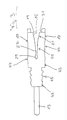
- the electrical connector according to the invention shown in FIGS. 1 and 2 is a stamped / bent part made from sheet metal, that from a bent into a U-shape with parallel contact arms 33 Material strips exist.
- the contact arms 33 are perpendicular from one the section of material forming the U-web 41, which is so far recessed that only comparatively narrow connecting strips between the two contact arms 33 remain.
- the two contact arms 33 are with the exception of their free end range, closer to that elsewhere is received, identical and carried out center symmetrically.
- Each contact arm 33 is provided with a central slot 15 which of two insulation displacement legs 17 is limited.
- the slot 15 ends before a holding section 43 of the contact arm 33, which is closer elsewhere is explained.
- the two limbs 17 delimiting the slot 15 of each contact arm 33 together form an insulation displacement terminal 11 on which a multi-core electrical line can be contacted with the contact arm 33.
- the line is preferably simultaneously in the two of each other spaced slots 15 pressed.
- the insulation of the line is formed when pressing with as cutting, in particular beveled leg edges cut open and displaced, whereby when the cable is inserted further, its cores with the leg edges come into contact and clamped between the legs 17 become.
- the barb-like projections can also be closer to the insulation displacement terminal 11 located areas of the long sides of the contact arm 33 be provided, e.g. to the straight in the embodiment according to FIGS. 1 and 2 Sections between the slot end and the transition into the Holding section 43.
- connection section 13 serves to solder the connector according to the invention to a circuit board, those below the receiving housing or below the receiving chamber is arranged for the connector.
- the slots 15 are each in an entry area 19 with shoulders 31 provided, each of a vertical and a parallel to the Slit axis extending leg edge are formed. Also prevent the shoulder portions 31 slipping when inserting the Connector used tool that in one of the shoulders 31st limited pre-area 19a is used.
- the entry area 19 goes into a funnel-like tapering convex curved leg edges delimited clamping area 27 over, which is longer than the entrance area 19.
- the cutting edges of the legs 17 provided in the entry region 19 extend, for example, from the starting area 19b delimiting edges of the shoulders 31 running parallel to the slot axis down to the convexly curved leg edges 21.
- the entry area forms - from the slot end viewed from - an extension of the clamping area 27 below Continuation of the convex curvature of the leg edges 21 and without step or edge-shaped transitions such that the slot is funnel-like extended up to the U-web 41 connecting the contact arms 33, the cutting edges in turn - now part of the clamping area forming - entrance area of the slot are formed.
- Such a slot design enables cables with a larger cross section be accommodated because the slot 15, i.e. the entrance area and the clamping area together, an opening up to the U-web 41 Funnel forms.
- the exact length and positioning of the areas designed as cutting edges the leg edges can in principle be chosen arbitrarily.
- the cutting edges can e.g. only provided in the straight start area 19b but can also extend into the clamping area 27.
- a short - viewed along the slot axis - is preferred Expansion of the cutting edges is provided, which is advantageous Way space is saved.
- the funnel-like tapering clamping area 27 ensures the rest Press in the line for an advantageous gentle sorting of the Conductive core forming wires, which creates unwanted free spaces or Gaps between the veins are eliminated and one for optimal Clamp fit order is achieved within a core network.
- An end region 29 adjoins the funnel-shaped clamping region 27 with a teardrop-shaped outline that is much shorter than that Clamping area 27 and shorter than the entry area 19.
- the maximal The width of the end region 29 is significantly larger than the slot width on End of the clamping area 27 and smaller than the slot width in the entry area 19th
- connection from the end region 29 the slot extension formed on the clamping region 27 extends the service life punching tools used to punch out the connector reduced wear can be extended. Besides, will this creates space for the insulation of the electrical conductor, the can flow into this area.
- the shape and size of the end region 29 are also determinative for the Elasticity and the clamping force of the legs 17, which is shown Drop shape of the end region 29 in connection with the rest Design features of the connector have been proven to be optimal in this regard Has.
- the recesses 35 have a small depth and are parallel to the longitudinal axis of the slot 15 extending longitudinal sides of the contact arm 33 limited.
- the length of the recesses 35 corresponds approximately that of the clamping area 27, the recesses 35 offset somewhat from the slot 15 in the direction of the holding section 43 are arranged.
- Each of the recesses 35 is followed by a convexly curved one Bulge 47, whose apex is approximately at the level of the End region 29 formed slot end.
- the width of the contact arm 33 is not on the latter Basic width in the entrance area 19, but on the reduced width in Area of the recesses 35 back.
- the bulges 47 and the Recesses 35 provide in connection with the other design features of the connector, in particular with the end region 29 of the Slot 15, for an optimal distribution of the forces and the tensions caused thereby.
- the bulges also provide 47 for a particularly good fit of the connector in the respective Receiving chamber.
- the embodiment of the connector according to the invention shown in FIG. 3 differs from that described in connection with FIGS. 1 and 2 Embodiment only in that the slot 15 in Clamping area 27 is designed asymmetrically in that one of the Clamp area 27 delimiting leg edges with an indentation is provided.
- the clamping area 27 thus has one of the entry area 19 and extension 51 spaced from the end region 29, in which the clamping area 27 one side of a concavely curved Thigh edge section is limited.
- the extension 51 means that there is more space in the clamping area 27 for the Cable cores are available, the one not provided with the extension 51 Thigh edge an optimal and particularly gentle guide and sorting of the wires guaranteed when the cable is pressed in. Furthermore, the extension 51 increases that for pulling out the line the force to be applied to the slot 15.
- the connector according to the invention can in principle for any multi-core electrical cables are used.
- the lines can both in terms of the number of wires, the cross section of the Distinguish wires or the overall cable cross-section from each other.
- the connector according to the invention ensures reliable Cutting and displacing the cable insulation in the entry area and an optimal, gentle sorting of the wires as well as a fixed one and secure press fit of the core bundle sorted by sorting through the thigh edges that run continuously towards each other limited basic shape of the clamping area 27, where due to the particular through the end region 29 of the slot 15 specifically adjusted elasticity and clamping force of the legs 17 in both electrical and mechanically optimal connection between the line or their cores and the component connected to the connection section 13, e.g. a circuit board.
Landscapes
- Connections By Means Of Piercing Elements, Nuts, Or Screws (AREA)
- Details Of Connecting Devices For Male And Female Coupling (AREA)
Abstract
Description
- Fig. 1
- eine perspektivische Teilansicht eines elektrischen Verbinders gemäß einer Ausführungsform der Erfindung,
- Fig. 2
- teilweise eine Seitenansicht des Verbinders von Fig. 1, und
- Fig. 3
- eine Seitenansicht eines elektrischen Verbinders gemäß einer weiteren Ausführungsform der Erfindung.
- 11
- Schneidklemme
- 13
- Anschlußabschnitt
- 15
- Schlitz
- 17
- Schenkel
- 19
- Eintrittsbereich
- 19a
- Vorbereich
- 19b
- Anfangsbereich
- 21
- Schenkelkante
- 27
- Klemmbereich
- 29
- Endbereich
- 31
- Schulterabschnitt
- 33
- Kontaktarm
- 35
- Aussparung
- 41
- U-Steg
- 43
- Halteabschnitt
- 45
- Längsseite
- 47
- Ausbuchtung
- 51
- Erweiterung, Einbuchtung
Claims (25)
- Elektrischer Verbinder für mehradrige elektrische Leitungen mit wenigstens einer Schneidklemme (11) zur Kontaktierung zumindest einer Leitung und
wenigstens einem Anschlußabschnitt (13) zur Kontaktierung eines mit der Leitung elektrisch zu verbindenden Bauteils,
wobei die Schneidklemme (11) von zwei einen Schlitz (15) für die Leitung begrenzenden Schneidklemmschenkeln (17) gebildet ist, die derart geformt sind, daß der Schlitz (15)einen zumindest bereichsweise von Schneidekanten der Schenkel (17) begrenzten Eintrittsbereich (19) aufweist,der in einen sich verjüngenden und eine von stetig aufeinander zu verlaufenden Schenkelkanten begrenzte Grundform aufweisenden Klemmbereich (27) übergeht, der länger als der Eintrittsbereich (19) ist undan den sich ein sich zunächst erweiternder und anschließend wieder bis zum Schlitzende verjüngender Endbereich (29) anschließt. - Verbinder nach Anspruch 2,
dadurch gekennzeichnet, daß der Klemmbereich (27) oder dessen Grundform von trichterartiger Gestalt ist. - Verbinder nach Anspruch 1 oder 2,
dadurch gekennzeichnet, daß der Klemmbereich (27) oder dessen Grundform von konvex gekrümmten Schenkelkanten begrenzt ist. - Verbinder nach einem der vorhergehenden Ansprüche,
dadurch gekennzeichnet, daß der Klemmbereich (27) von seiner Grundform durch wenigstens eine Erweiterung (51) abweicht, die bevorzugt in Form einer im Vergleich zur Länge des Klemmbereiches (27) kurzen Einbuchtung in wenigstens einer der Schenkelkanten vorgesehen ist. - Verbinder nach Anspruch 4,
dadurch gekennzeichnet, daß die Erweiterung (51) an einer vom Eintrittsbereich (19) und vom Endbereich (29) beabstandeten Zwischenstelle des Klemmbereiches (27) gelegen ist. - Verbinder nach Anspruch 4 oder 5,
dadurch gekennzeichnet, daß zur Bildung der Erweiterung (51) lediglich eine der Schenkelkanten von ihrem die Grundform des Klemmbereiches (27) bestimmenden Verlauf abweicht. - Verbinder nach einem der vorhergehenden Ansprüche,
dadurch gekennzeichnet, daß der Endbereich (29) kürzer als der Klemmbereich (27) ist. - Verbinder nach einem der vorhergehenden Ansprüche,
dadurch gekennzeichnet, daß der Endbereich (29) kreis- oder tropfenförmig ausgebildet ist. - Verbinder nach einem der vorhergehenden Ansprüche,
dadurch gekennzeichnet, daß im Eintrittsbereich (19) von etwa senkrecht zur Längsachse des Schlitzes (15) verlaufenden Schenkelkanten begrenzte Schulterabschnitte (31) vorgesehen sind. - Verbinder nach einem der vorhergehenden Ansprüche,
dadurch gekennzeichnet, daß den Schenkelkanten (21) des Eintrittsbereiches (19) etwa parallel zur Längsachse des Schlitzes (15) verlaufende Schenkelkanten vorgelagert sind, die einen Anfangsbereich (19b) des Eintrittsbereiches (19) begrenzen. - Verbinder nach einem der vorhergehenden Ansprüche,
dadurch gekennzeichnet, daß dem Anfangsbereich (19b) ein vorzugsweise von etwa parallel zur Längsachse des Schlitzes (15) verlaufenden Schenkelkanten begrenzter Vorbereich (19a) vorgelagert ist. - Verbinder nach Anspruch 11,
dadurch gekennzeichnet, daß der Übergang vom Vorbereich (19a) in den Anfangsbereich (19b) von Schulterabschnitten (31) gebildet ist, die vorzugsweise jeweils von rechtwinklig zueinander verlaufenden Schenkelkanten gebildet sind. - Verbinder nach einem der Ansprüche 1 bis 8,
dadurch gekennzeichnet, daß der Eintrittsbereich und der Klemmbereich zusammen eine sich trichterartig verjüngende Grundform aufweisen und insbesondere unter Vermeidung von Stufen in den Schenkelkanten fließend ineinander übergehen. - Verbinder nach einem der vorhergehenden Ansprüche,
dadurch gekennzeichnet, daß die maximale Breite des Klemmbereiches (27) kleiner und insbesondere wesentlich kleiner ist als dessen Länge. - Verbinder nach einem der vorhergehenden Ansprüche,
dadurch gekennzeichnet, daß der Klemmbereich (27) jeweils länger ist als der Eintrittsbereich (19) und/oder als der Endbereich (29). - Verbinder nach einem der vorhergehenden Ansprüche,
dadurch gekennzeichnet, daß die maximale Breite des Endbereiches (29) kleiner ist als die Schlitzbreite im Eintrittsbereich (19). - Verbinder nach einem der vorhergehenden Ansprüche,
dadurch gekennzeichnet, daß er zumindest in Höhe des Eintrittsbereiches (19) eine Breite aufweist, die derart auf eine jeweilige, insbesondere als Kammer ausgebildete Verbinderaufnahme abgestimmt ist, daß diese beim Einführen einer Leitung in den Schlitz (15) ein Aufspreizen der Schenkel (17) zwar ermöglicht, jedoch auf ein vorgegebenes Maß begrenzt. - Verbinder nach einem der vorhergehenden Ansprüche,
dadurch gekennzeichnet, daß der Schlitz (15) in einem streifenförmigen und eine zumindest im Bereich des Schlitzes (15) etwa rechteckige Grundform aufweisenden Kontaktarm (33) ausgebildet ist, dessen parallel zum Schlitz (15) verlaufenden Längsseiten jeweils mit zumindest einer Aussparung (35) versehen sind. - Verbinder nach Anspruch 18,
dadurch gekennzeichnet, daß die Aussparungen (35) von zumindest im wesentlichen parallel zum Schlitz (15) verlaufenden Längsseiten des Kontaktarmes (33) begrenzt sind. - Verbinder nach Anspruch 18 oder 19,
dadurch gekennzeichnet, daß die Aussparungen (35) jeweils zumindest näherungsweise die gleiche Länge wie der Klemmbereich (27) des Schlitzes (15) aufweisen und etwa in Höhe des Klemmbereiches (27) gelegen sind. - Verbinder nach einem der Ansprüche 18 bis 20,
dadurch gekennzeichnet, daß die Tiefe der Aussparungen (35) wesentlich kleiner ist als deren Länge und insbesondere kleiner als die minimale Schlitzbreite. - Verbinder nach einem der vorhergehenden Ansprüche,
dadurch gekennzeichnet, daß die Längsseiten des Kontaktarmes (33) jeweils insbesondere im Anschluß an Aussparungen (35) mit einer bevorzugt im Vergleich zur Länge der Aussparungen (35) kurzen Ausbuchtung (47) versehen sind. - Verbinder nach einem der vorhergehenden Ansprüche,
dadurch gekennzeichnet, daß der Schlitz (15) und insbesondere ein mit dem Schlitz (15) versehener Kontaktarm (33) bezüglich der Längsachse des Schlitzes (15) symmetrisch ausgeführt sind. - Verbinder nach einem der vorhergehenden Ansprüche,
dadurch gekennzeichnet, daß er in eine U-Form mit zwei etwa parallel verlaufenden und jeweils zumindest einen von dem U-Steg (41) ausgehenden Schlitz (15) aufweisenden Kontaktarmen (33) gebogen ist, die bevorzugt zumindest im Bereich der Schlitze (15) identisch ausgeführt sind. - Verbinder nach einem der vorhergehenden Ansprüche,
dadurch gekennzeichnet, daß die Schneidklemme (11) in einen Halteabschnitt (43) übergeht, der mit widerhakenartigen Vorsprüngen versehene, insbesondere sägezahnartig ausgebildete Längsseiten (45) aufweist. -.-.-.
Applications Claiming Priority (2)
| Application Number | Priority Date | Filing Date | Title |
|---|---|---|---|
| DE10129615 | 2001-06-20 | ||
| DE10129615A DE10129615A1 (de) | 2001-06-20 | 2001-06-20 | Elektrischer Verbinder |
Publications (2)
| Publication Number | Publication Date |
|---|---|
| EP1271695A1 true EP1271695A1 (de) | 2003-01-02 |
| EP1271695B1 EP1271695B1 (de) | 2005-03-16 |
Family
ID=7688746
Family Applications (1)
| Application Number | Title | Priority Date | Filing Date |
|---|---|---|---|
| EP02013507A Expired - Lifetime EP1271695B1 (de) | 2001-06-20 | 2002-06-17 | Elektrischer Verbinder |
Country Status (2)
| Country | Link |
|---|---|
| EP (1) | EP1271695B1 (de) |
| DE (2) | DE10129615A1 (de) |
Cited By (1)
| Publication number | Priority date | Publication date | Assignee | Title |
|---|---|---|---|---|
| WO2016124636A1 (de) | 2015-02-03 | 2016-08-11 | Brose Fahrzeugteile GmbH & Co. Kommanditgesellschaft, Würzburg | Elektromotor und schalteinheit hierfür |
Citations (4)
| Publication number | Priority date | Publication date | Assignee | Title |
|---|---|---|---|---|
| EP0320310A2 (de) * | 1987-12-11 | 1989-06-14 | Molex Incorporated | Isolierungsschneidender Anschluss mit hohem Kontaktdruck für mehradrige Kabel |
| US4952169A (en) * | 1989-06-27 | 1990-08-28 | Amp Incorporated | Sealed electrical connector employing insulation displacement terminals |
| DE4238533A1 (de) * | 1992-11-14 | 1994-05-19 | Minnesota Mining & Mfg | Kontaktelement für Steckverbindung |
| DE19807938A1 (de) * | 1997-12-18 | 1999-08-26 | Whitaker Corp | Steckverbinder bestehend aus einem Gehäuse und mindestens einem Kontakt |
Family Cites Families (2)
| Publication number | Priority date | Publication date | Assignee | Title |
|---|---|---|---|---|
| DE4225078A1 (de) * | 1992-07-29 | 1994-02-03 | Grote & Hartmann | Schneidklemmkontaktelemente mit Codierungseinrichtung |
| DE19937313C1 (de) * | 1999-08-10 | 2001-08-23 | Fritz Eigen | Messerkontakt |
-
2001
- 2001-06-20 DE DE10129615A patent/DE10129615A1/de not_active Withdrawn
-
2002
- 2002-06-17 EP EP02013507A patent/EP1271695B1/de not_active Expired - Lifetime
- 2002-06-17 DE DE50202462T patent/DE50202462D1/de not_active Expired - Fee Related
Patent Citations (4)
| Publication number | Priority date | Publication date | Assignee | Title |
|---|---|---|---|---|
| EP0320310A2 (de) * | 1987-12-11 | 1989-06-14 | Molex Incorporated | Isolierungsschneidender Anschluss mit hohem Kontaktdruck für mehradrige Kabel |
| US4952169A (en) * | 1989-06-27 | 1990-08-28 | Amp Incorporated | Sealed electrical connector employing insulation displacement terminals |
| DE4238533A1 (de) * | 1992-11-14 | 1994-05-19 | Minnesota Mining & Mfg | Kontaktelement für Steckverbindung |
| DE19807938A1 (de) * | 1997-12-18 | 1999-08-26 | Whitaker Corp | Steckverbinder bestehend aus einem Gehäuse und mindestens einem Kontakt |
Cited By (2)
| Publication number | Priority date | Publication date | Assignee | Title |
|---|---|---|---|---|
| WO2016124636A1 (de) | 2015-02-03 | 2016-08-11 | Brose Fahrzeugteile GmbH & Co. Kommanditgesellschaft, Würzburg | Elektromotor und schalteinheit hierfür |
| EP3402047A1 (de) | 2015-02-03 | 2018-11-14 | Brose Fahrzeugteile GmbH & Co. Kommanditgesellschaft, Würzburg | Elektromotor und schalteinheit hierfür |
Also Published As
| Publication number | Publication date |
|---|---|
| DE50202462D1 (de) | 2005-04-21 |
| DE10129615A1 (de) | 2003-01-02 |
| EP1271695B1 (de) | 2005-03-16 |
Similar Documents
| Publication | Publication Date | Title |
|---|---|---|
| EP3324490B1 (de) | Federklemmkontakt zur kontaktierung elektrischer leiter, leiteranschlussklemme und verfahren zur herstellung eines federklemmkontakts | |
| DE1665163C3 (de) | Verbinder zum Herstellen lötfreier elektrischer Verbindungen mit Leitern eines Mehrfach-Flachkabels | |
| DE2711723C2 (de) | Verfahren zum Anschließen eines feinen Drahtes und Verbinder zur Durchführung dieses Verfahrens | |
| EP0283427B1 (de) | Schneidklemm-Hülsenkontakt | |
| DE1765818C3 (de) | Verbindungsklemme zum Andrücken an elektrische Drähte | |
| DE69603318T2 (de) | Vorrichtung für elektrische Kontakte mit Isolationsverschiebung | |
| DE69800778T2 (de) | Schneidklemmkontakt | |
| EP0893845A2 (de) | Schneidklemm-Kontakt sowie Anschlussleiste oder -modul und Reihenklemme mit einem Schneidklemm-Kontakt | |
| DE69401671T2 (de) | Elektrischer Sammelverbinder | |
| DE2637378C2 (de) | Verbinderkontakt | |
| DE102004019360A1 (de) | Isolierdraht-Anschlusskontaktelement | |
| DE2048889A1 (de) | ||
| EP0210945B1 (de) | Vorrichtung zum Anschliessen und Verbinden von Kabeladern | |
| DE2840308A1 (de) | Kontaktelement fuer eine verbindungsvorrichtung | |
| DE2342408C3 (de) | ||
| EP1008205B1 (de) | Reihenklemme zum abisolierungsfreien anschluss isolierter leiter | |
| DE2342408A1 (de) | Elektrisches klemmanschlusstueck | |
| EP1251589B1 (de) | Schraubenlose Anschlussklemme | |
| DE3850064T2 (de) | Isolierungsschneidender Anschluss mit hohem Kontaktdruck für mehradrige Kabel. | |
| DE4320539C2 (de) | Leitungsdraht-Verbindungsklemme | |
| DE69913397T2 (de) | Schneidklemme | |
| DE2621502A1 (de) | Anschlussvorrichtung fuer elektrische leiter | |
| EP1271695B1 (de) | Elektrischer Verbinder | |
| DE10111190B4 (de) | Anschlussklemme mit Kontaktstück | |
| EP0892997B1 (de) | Kabelsteckverbinder |
Legal Events
| Date | Code | Title | Description |
|---|---|---|---|
| PUAI | Public reference made under article 153(3) epc to a published international application that has entered the european phase |
Free format text: ORIGINAL CODE: 0009012 |
|
| AK | Designated contracting states |
Kind code of ref document: A1 Designated state(s): AT BE CH CY DE DK ES FI FR GB GR IE IT LI LU MC NL PT SE TR |
|
| AX | Request for extension of the european patent |
Free format text: AL;LT;LV;MK;RO;SI |
|
| AKX | Designation fees paid | ||
| 17P | Request for examination filed |
Effective date: 20030205 |
|
| RBV | Designated contracting states (corrected) |
Designated state(s): DE FR IT |
|
| REG | Reference to a national code |
Ref country code: DE Ref legal event code: 8566 |
|
| 17Q | First examination report despatched |
Effective date: 20031216 |
|
| GRAP | Despatch of communication of intention to grant a patent |
Free format text: ORIGINAL CODE: EPIDOSNIGR1 |
|
| GRAS | Grant fee paid |
Free format text: ORIGINAL CODE: EPIDOSNIGR3 |
|
| GRAA | (expected) grant |
Free format text: ORIGINAL CODE: 0009210 |
|
| REG | Reference to a national code |
Ref country code: DE Ref legal event code: 8570 |
|
| AK | Designated contracting states |
Kind code of ref document: B1 Designated state(s): DE FR IT |
|
| PG25 | Lapsed in a contracting state [announced via postgrant information from national office to epo] |
Ref country code: IT Free format text: LAPSE BECAUSE OF FAILURE TO SUBMIT A TRANSLATION OF THE DESCRIPTION OR TO PAY THE FEE WITHIN THE PRESCRIBED TIME-LIMIT;WARNING: LAPSES OF ITALIAN PATENTS WITH EFFECTIVE DATE BEFORE 2007 MAY HAVE OCCURRED AT ANY TIME BEFORE 2007. THE CORRECT EFFECTIVE DATE MAY BE DIFFERENT FROM THE ONE RECORDED. Effective date: 20050316 |
|
| REG | Reference to a national code |
Ref country code: IE Ref legal event code: FG4D Free format text: GERMAN |
|
| REF | Corresponds to: |
Ref document number: 50202462 Country of ref document: DE Date of ref document: 20050421 Kind code of ref document: P |
|
| PLBE | No opposition filed within time limit |
Free format text: ORIGINAL CODE: 0009261 |
|
| STAA | Information on the status of an ep patent application or granted ep patent |
Free format text: STATUS: NO OPPOSITION FILED WITHIN TIME LIMIT |
|
| ET | Fr: translation filed | ||
| 26N | No opposition filed |
Effective date: 20051219 |
|
| PGFP | Annual fee paid to national office [announced via postgrant information from national office to epo] |
Ref country code: DE Payment date: 20070614 Year of fee payment: 6 |
|
| PGFP | Annual fee paid to national office [announced via postgrant information from national office to epo] |
Ref country code: FR Payment date: 20070608 Year of fee payment: 6 |
|
| REG | Reference to a national code |
Ref country code: FR Ref legal event code: ST Effective date: 20090228 |
|
| PG25 | Lapsed in a contracting state [announced via postgrant information from national office to epo] |
Ref country code: DE Free format text: LAPSE BECAUSE OF NON-PAYMENT OF DUE FEES Effective date: 20090101 |
|
| PG25 | Lapsed in a contracting state [announced via postgrant information from national office to epo] |
Ref country code: FR Free format text: LAPSE BECAUSE OF NON-PAYMENT OF DUE FEES Effective date: 20080630 |