EP1270938A2 - Pompe doseuse pour un fluide visqueux - Google Patents
Pompe doseuse pour un fluide visqueux Download PDFInfo
- Publication number
- EP1270938A2 EP1270938A2 EP02013231A EP02013231A EP1270938A2 EP 1270938 A2 EP1270938 A2 EP 1270938A2 EP 02013231 A EP02013231 A EP 02013231A EP 02013231 A EP02013231 A EP 02013231A EP 1270938 A2 EP1270938 A2 EP 1270938A2
- Authority
- EP
- European Patent Office
- Prior art keywords
- bore
- pump body
- pistons
- sleeve
- chamber
- Prior art date
- Legal status (The legal status is an assumption and is not a legal conclusion. Google has not performed a legal analysis and makes no representation as to the accuracy of the status listed.)
- Withdrawn
Links
Images


Classifications
-
- B—PERFORMING OPERATIONS; TRANSPORTING
- B67—OPENING, CLOSING OR CLEANING BOTTLES, JARS OR SIMILAR CONTAINERS; LIQUID HANDLING
- B67D—DISPENSING, DELIVERING OR TRANSFERRING LIQUIDS, NOT OTHERWISE PROVIDED FOR
- B67D7/00—Apparatus or devices for transferring liquids from bulk storage containers or reservoirs into vehicles or into portable containers, e.g. for retail sale purposes
- B67D7/06—Details or accessories
-
- F—MECHANICAL ENGINEERING; LIGHTING; HEATING; WEAPONS; BLASTING
- F04—POSITIVE - DISPLACEMENT MACHINES FOR LIQUIDS; PUMPS FOR LIQUIDS OR ELASTIC FLUIDS
- F04B—POSITIVE-DISPLACEMENT MACHINES FOR LIQUIDS; PUMPS
- F04B13/00—Pumps specially modified to deliver fixed or variable measured quantities
- F04B13/02—Pumps specially modified to deliver fixed or variable measured quantities of two or more fluids at the same time
-
- F—MECHANICAL ENGINEERING; LIGHTING; HEATING; WEAPONS; BLASTING
- F04—POSITIVE - DISPLACEMENT MACHINES FOR LIQUIDS; PUMPS FOR LIQUIDS OR ELASTIC FLUIDS
- F04B—POSITIVE-DISPLACEMENT MACHINES FOR LIQUIDS; PUMPS
- F04B7/00—Piston machines or pumps characterised by having positively-driven valving
- F04B7/04—Piston machines or pumps characterised by having positively-driven valving in which the valving is performed by pistons and cylinders coacting to open and close intake or outlet ports
- F04B7/045—Two pistons coacting within one cylinder
Definitions
- the invention relates to a device for the metered delivery of a viscous liquid in the Preamble of claim 1 mentioned type.
- a device for the metered delivery of a viscous liquid in the preamble of claim 1 mentioned type is known from the patent application SG 0074739 in Singapore.
- This device includes a pump body with a bore that connects an inlet chamber and an outlet chamber.
- two pistons are reciprocated between the inlet chamber and the outlet chamber emotional.
- a slot of variable width is formed between the end faces of the two pistons, so that the liquid in the inlet chamber fills the slot and in the outlet chamber out of the slot is pressed.
- additional bores run in parallel Guide rods available.
- This device has two disadvantages. When used to apply glue comes silver flakes contained in the adhesive into the outside of the pump body and from there into the the guide rod receiving bores arrive, causing the guide rods to stick together leads. In addition, the friction of the guide rods in the holes is too great.
- the invention has for its object to remedy the above-mentioned shortcomings.
- the invention discloses on the one hand an improved drive mechanism and certain constructive Measures that prevent the drive mechanism from sticking and, on the other hand, a pump body, which is particularly suitable for the metered delivery of adhesives, the silver flakes contain.
- This pump body is characterized by the fact that the bore, the inlet chamber and connecting the outlet chamber is elongated, with the two pistons reciprocating in the bore be moved, form a gap seal at the ends of the bore. So that the gap seal the pistons and the pump body, or one in the pump body, are adequately sealed built-in sleeve that contains the bore, paired from suitable materials and on the other hand manufactured with the highest precision.
- the device shows a device for the metered delivery of a viscous liquid, which is used for metering and dispensing very small amounts of adhesive.
- the device consists essentially of a pump body 1 with a two piston 2 and 3 receiving bore 4, one as an inlet chamber serves first chamber 5 and a second chamber 6 serving as an outlet chamber, and a drive mechanism 7 for the reciprocating movement of the two pistons 2 and 3 between the inlet chamber 5 and the outlet chamber 6.
- the drive mechanism 7 is designed such that the width of a formed between the opposite end faces of the pistons 2 and 3 Slit 8 varies during the reciprocating movement of the pistons 2, 3 in a predetermined manner.
- the pump body 1 has a recess on both sides of the bore 4, into which a bearing body 9 is inserted.
- the bearing body 9 contain a concentric to the bore 4 Hole that is flared towards the outside.
- the bearing body 9 also take an elastic deformable sealing element 10.
- the sealing element 10 also includes a sealing lip 11 a central opening for receiving the piston 2 or 3.
- the opening of the sealing lip 11 is smaller than the diameter of the pistons 2 and 3.
- the sealing lip 11 therefore encloses the corresponding pistons 2 or 3 with a tight fit. During the back and forth movement of the corresponding Piston 2 and 3, the sealing lip 11 is elastically deformed.
- the pump body 1 is already prepared for use as a write head, in which the chamber 6 serving as an outlet as a writing nozzle 12 or for equipping with a writing nozzle is trained.
- the viscous liquid is drawn out of a tube through a hose Not shown liquid reservoir supplied.
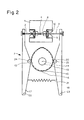
- the drive mechanism 7 will now be explained in more detail with reference to FIG. 2, which shows the metering device in Top view on the level of line I - I of FIG. 1 shows.
- the drive mechanism 7 includes one Motor 13, on whose shaft 14 two cams 15 and 16 are fastened, two swivel arms 17 and 18 each with a ball bearing 19 or 20 and a spring 21.
- One end of the first swivel arm 17 is pivotable about an axis 22 running perpendicular to the plane of the drawing, while at the other end the first pivot arm 17 of the piston 2 is releasably attached.
- one end of the second Swivel arm 18 pivotable about an axis 23 running parallel to the first axis 22, while on the other end of the second swivel arm 18 the other piston 3 is releasably attached.
- Pistons 2, 3 are preferably screwed into the corresponding swivel arm 17, 18.
- the ball bearing 19 of the first Swivel arm 17 consists of a disc rotatable about an axis 24, which is on the first cam 15 rests.
- the ball bearing 20 of the second swivel arm 18 consists of an axis 25 rotatable disc, which rests on the second cam 16.
- the spring 21 connects the two Swivel arms 17 and 18, thus ensuring that the ball bearings 19 and 20 are in permanent contact with the corresponding cam 15 or 16 remain.
- the bearing body 9 are preferably made of an abrasion-resistant plastic, while the pistons 2 and 3 preferably consist of steel.
- the bore of the bearing body 9 takes over the leadership of corresponding pistons 2 and 3, respectively. Since the swivel arms 17 and 18 rotate about the axis 22 or 23 execute, the tips of pistons 2 and 3 would move in a circular path if they would not be prevented.
- the bore of the bearing body 9 has the task of the corresponding To guide the piston so that the tip of the piston in the bore 4 along a possible straight path moves.
- the guidance and storage of the piston in the bore of the bearing body 9 leads to ensure that the piston only in the area between the swivel arm and the bore of the bearing body 9 is elastically deformed while the piston in the area between the bore of the bearing body 9 and remains straight within the bore 4.
- the device as a write head for applying adhesive to a semiconductor chip mounting substrate can be used, their mass must be as small as possible, since the write head Great accelerations occur during the writing movement.
- the ball bearings 19 and 20 be light and the load on the ball bearings 19 and 20 by the swivel arms 17 and 18 must not exceed certain limits, otherwise the ball bearings 19 and 20 will be damaged.
- the force with which the spring 21 pulls the swivel arms 17 and 18 must, on the one hand, be large enough on the other hand, so that the ball bearings never lose contact with the corresponding cam is her due to the resilience of the ball bearings 19, 20 an upper limit that does not exceed may be.
- the motor rotates at high speeds in the range from 1000 to 10,000 Revolutions per minute.
- the centrifugal forces exerted on the swivel arms 17, 18 are proportional to Mass of the swivel arms 17, 18.
- the force exerted by the spring 21 must be greater than that maximum centrifugal force so that the swivel arms 17, 18 do not lift off the cam plate 15 or 16. It has been shown that a material must be used for the swivel arms 17, 18 specific gravity is less than the specific gravity of aluminum.
- the two swivel arms 17 and 18 are therefore preferably made of plastic.
- the plastic must also be large Have rigidity so that the pivot arms 17 and 18 do not flap, which is not intended Modulation of the width of the slot 8 between the pistons 2 and 3 would result.
- FIG. 3A-F schematically show the relative position of pistons 2 and 3 during a single one Rotation of the cam discs 15 and 16 in six different angular positions.
- the enlarged slot immediately fills with liquid (Fig. 3B).
- the piston 3 then stands still (FIG.
- the distance between the two pistons 2 and 3 is always greater than Is zero.
- the width of the slot between pistons 2 and 3 is between 0.4 mm and 0.7 mm varies.
- the slot 8 in the inlet chamber is then filled with adhesive more quickly.
- the device becomes more robust with respect to assembly tolerances.
- the dosing device described is suitable for all types of adhesives, with the exception of adhesives, contain the silver flakes as filling material.
- the silver flakes have the unwanted Property of being deposited on pistons 2 and 3. This causes the sealing lips to slow but are constantly rubbed off and gradually destroyed.
- the Pump body 1 described below with reference to FIG. 5.
- the pump body 1 shows the pump body 1 in cross section, the right part of the figure being cut off.
- the pump body 1 has a sleeve 28 which is provided with the bore 4 in the longitudinal direction, which receives the two pistons 2 and 3.
- the bore 4 is widened at the ends, so that Pistons 2 and 3 can be easily inserted when assembling the pump.
- the sleeve 28 contains two further bores 29 and 30, which are orthogonal to the bore 4 and and their one end in the bore 4 and the other end in the inlet chamber 5 and outlet chamber 6 in Pump body 1 opens.
- the bore 4 thus extends laterally across the inlet chamber 5 as well the outlet chamber 6.
- the bore 4 takes over both the bearing of the two pistons 2 and 3 as well as the sealing of the pump section.
- the bore 4 takes over thus also the function of the sealing lips 11 of the first embodiment.
- the hole 4 and the corresponding pistons 2 or 3 form a gap seal.
- the sleeve 28 and the pistons 2 and 3 with great precision and from each other Materials are made. Good results have been obtained when pistons 2 and 3 and sleeve 28 each consist of a hard metal or if the pistons 2 and 3 from a tool steel and the sleeve 28 are made of ceramic.
- the radius of the bore 4 is, for example, with a value of 201 microns ⁇ 0.5 ⁇ m, and the radius of pistons 2 and 3 with a value of 200 ⁇ m ⁇ 0.15 ⁇ m.
- Suitable hard metals are e.g. WC (tungsten carbide), TiC (Titanium carbide), TaC (tantalum carbide) or mixtures of these carbides mixed with Co (cobalt) were sintered. Ceramic materials have the advantage of higher abrasion resistance, but the disadvantage lower thermal conductivity than hard metals.
- the diameter of the bores 29 and 30 is advantageously larger than the diameter of the bore 4, so that the adhesive as quickly as possible in the between the opposite faces of the pistons 2 and 3 formed slot 8 can be pressed in or pressed out.
- the pump body 1 has two vertically running blind holes 31 and 32, which are on both sides the sleeve 28 are arranged and communicate with the bore 4. These blind holes 31 and 32 serve as a result of insufficient sealing effect of the gap seal in the course of Time to absorb adhesive emerging from hole 4. If the pump is in regular Spaces is cleaned, then the adhesive can be removed from the blind holes 31 and 32 before other parts of the pump become dirty.
- the drive mechanism 7 described with reference to FIG. 2 has the special feature that the Point 33, where the rotational movement of the first swivel arm 17 into the reciprocating movement of the piston 2 is implemented, moved back and forth on a circular path.
- these attachment points and therefore pistons 2 and 3 should not be on the circular path, but move back and forth along a straight line.
- the bearing body 9 installed in the pump body 1 has a concentric one to the bore 4 extending bore 34 in which a sleeve 35 is slidably mounted.
- the hole 34 forms a bearing for the sleeve 35.
- the sleeve 35 has a longitudinal bore 36, one end of which End of the piston 2 picks up.
- the longitudinal bore 36 extends coaxially to the bore 4.
- the longitudinal bore 36 is widened and forms an enlarged cavity 37.
- a pin 38 connects the swivel arm 17 to the sleeve 35.
- the pin 38 is on the one hand via a Coupling member 39 releasably on the swivel arm 17 and on the other hand firmly in the longitudinal bore 36 of the sleeve 35 attached. If the end of the swivel arm 17 moves back and forth on the circular path, then it moves the sleeve 35 and thus the piston 2 back and forth.
- the bearing body 9 now ensures that the sleeve 35 moves along a straight line.
- the pin 38 is on the way from the swivel arm 17th bent to the longitudinal bore 36 of the sleeve 35.
- the piston 2, however, is due to the circular path movement of the swivel arm 17 is not loaded, since its movement by the one supported in the bearing body 9 Sleeve 35 is guided.
- the coupling member 39 has a projecting edge which surrounds the end of the sleeve 35, the edge of the coupling member 39 and the sleeve 35 are separated by a small gap. This construction ensures that pin 38 will not be damaged during pump maintenance can, since the edge of the coupling member 39 comes to a stop on the sleeve 35 before the pin 38th can be bent too tight.
- the sleeve 35 is provided at its front end with a thread on which one through Blind hole 31 inserted nut 40 is screwed on. This prevents the Piston 2 can fall out of the pump body 1 during maintenance of the pump.
- a particular advantage of this pump body 1 is that the tips of the pistons 2 and 3 are always inside the hole 4 remain.
- the pump body 1, the sleeve 28 and the two bearing bodies 9 separate parts that can be manufactured separately.
- This version has the advantage that the for the sleeve 28 and the two pistons 2 and 3 used materials optimally matched can be.
- the materials used for the bearing body 9 and the sleeve 35 can also be used be optimally coordinated.
- the material for the pump body 1 can also be so can be selected so that the pump body 1 has optimal properties, for example a high one Thermal conductivity, or can be produced in a simple manner.
- Another variant consists in producing the sleeves 28 and 35 from the same material and thus as one piece.
- Pistons 2 and 3 can also be driven directly, i.e. the bearing body 9 and the sleeve 35 can be omitted if the drive in the direction of the axis defined by the bore 4.
Applications Claiming Priority (2)
| Application Number | Priority Date | Filing Date | Title |
|---|---|---|---|
| CH11942001 | 2001-06-28 | ||
| CH11942001 | 2001-06-28 |
Publications (1)
| Publication Number | Publication Date |
|---|---|
| EP1270938A2 true EP1270938A2 (fr) | 2003-01-02 |
Family
ID=4562348
Family Applications (1)
| Application Number | Title | Priority Date | Filing Date |
|---|---|---|---|
| EP02013231A Withdrawn EP1270938A2 (fr) | 2001-06-28 | 2002-06-17 | Pompe doseuse pour un fluide visqueux |
Country Status (6)
| Country | Link |
|---|---|
| US (2) | US6705845B2 (fr) |
| EP (1) | EP1270938A2 (fr) |
| JP (1) | JP2003097750A (fr) |
| KR (1) | KR20030004028A (fr) |
| CN (1) | CN1267207C (fr) |
| TW (1) | TW575512B (fr) |
Cited By (1)
| Publication number | Priority date | Publication date | Assignee | Title |
|---|---|---|---|---|
| EP4163186A1 (fr) * | 2021-10-07 | 2023-04-12 | Weber-Hydraulik Gmbh | Pompe hydraulique ou pneumatique |
Families Citing this family (16)
| Publication number | Priority date | Publication date | Assignee | Title |
|---|---|---|---|---|
| EP1270938A2 (fr) * | 2001-06-28 | 2003-01-02 | Esec Trading S.A. | Pompe doseuse pour un fluide visqueux |
| US20080118376A1 (en) * | 2006-11-20 | 2008-05-22 | Brian Leonard Verrilli | Translational displacement pump and bulk fluid re-supply system |
| DE102007053073A1 (de) * | 2007-11-07 | 2009-06-04 | Dürr Systems GmbH | Applikationssystem |
| US8702405B2 (en) | 2007-11-17 | 2014-04-22 | Brian Leonard Verrilli | Twisting translational displacement pump cartridge |
| US8986253B2 (en) | 2008-01-25 | 2015-03-24 | Tandem Diabetes Care, Inc. | Two chamber pumps and related methods |
| DE202008007730U1 (de) * | 2008-06-10 | 2008-09-11 | Richter, Siegfried, Dipl.-Ing. (FH) | Elektrischer Schwingantrieb |
| US8408421B2 (en) | 2008-09-16 | 2013-04-02 | Tandem Diabetes Care, Inc. | Flow regulating stopcocks and related methods |
| US8650937B2 (en) | 2008-09-19 | 2014-02-18 | Tandem Diabetes Care, Inc. | Solute concentration measurement device and related methods |
| WO2010099490A2 (fr) | 2009-02-27 | 2010-09-02 | Tandem Diabetes Care, Inc. | Procédés et dispositifs pour la détermination d'un volume de réservoir d'écoulement |
| US9250106B2 (en) | 2009-02-27 | 2016-02-02 | Tandem Diabetes Care, Inc. | Methods and devices for determination of flow reservoir volume |
| EP3284494A1 (fr) | 2009-07-30 | 2018-02-21 | Tandem Diabetes Care, Inc. | Système de pompe à perfusion portable |
| US9180242B2 (en) | 2012-05-17 | 2015-11-10 | Tandem Diabetes Care, Inc. | Methods and devices for multiple fluid transfer |
| US9555186B2 (en) | 2012-06-05 | 2017-01-31 | Tandem Diabetes Care, Inc. | Infusion pump system with disposable cartridge having pressure venting and pressure feedback |
| US9173998B2 (en) | 2013-03-14 | 2015-11-03 | Tandem Diabetes Care, Inc. | System and method for detecting occlusions in an infusion pump |
| WO2016124589A1 (fr) * | 2015-02-02 | 2016-08-11 | Sanofi-Aventis Deutschland Gmbh | Procédé d'amorçage d'une pompe médicale |
| CN114754292B (zh) * | 2022-05-05 | 2023-07-14 | 济南林青铸造技术有限公司 | 一种智能控制的液料连续精准定量输出系统及其运行方法 |
Family Cites Families (19)
| Publication number | Priority date | Publication date | Assignee | Title |
|---|---|---|---|---|
| US2169807A (en) | 1938-03-04 | 1939-08-15 | George R Lyon | Compressor |
| US2529457A (en) * | 1945-04-28 | 1950-11-07 | Arenco Ab | Apparatus for delivering measured quantities of material |
| US3302578A (en) * | 1965-04-28 | 1967-02-07 | H V Hardman Co Inc | Metering pump |
| US3471079A (en) * | 1967-09-21 | 1969-10-07 | Elman B Myers | Reciprocating vacuum pump |
| US3695788A (en) | 1970-01-09 | 1972-10-03 | Bernard A Loomans | Apparatus for pumping fluids |
| US3802608A (en) * | 1972-04-10 | 1974-04-09 | Packard Instrument Co Inc | Liquid metering device with concentric pistons and unidirectional liquid flow |
| US3975960A (en) * | 1974-03-15 | 1976-08-24 | Technicon Instruments Corporation | Manual fluid sampler with overstroke |
| US4688609A (en) * | 1982-09-23 | 1987-08-25 | Fluid Packaging Company | System including nozzle for injecting molten product into deodorant stick containers |
| FR2617541A1 (fr) | 1987-06-30 | 1989-01-06 | Europ Composants Electron | Dispositif automatique de coulage d'une resine avec un dosage volumetrique de precision |
| US4941808A (en) * | 1988-06-29 | 1990-07-17 | Humayun Qureshi | Multi-mode differential fluid displacement pump |
| DE9115838U1 (fr) * | 1991-12-20 | 1992-02-13 | Hans Richard Rappenhoener | |
| US5467899A (en) * | 1994-02-08 | 1995-11-21 | Liquid Control Corporation | Dispensing device for flowable materials |
| JP3129099B2 (ja) * | 1994-09-09 | 2001-01-29 | ブラザー工業株式会社 | 駆動装置付ポンプ |
| JPH10332214A (ja) * | 1997-05-29 | 1998-12-15 | Aisin Seiki Co Ltd | リニアコンプレッサ |
| TW504567B (en) | 1998-08-05 | 2002-10-01 | Esec Trading Sa | Device for the metered delivery of a viscous liquid |
| JP3173492B2 (ja) * | 1999-02-05 | 2001-06-04 | 株式会社移動体通信先端技術研究所 | リニア圧縮機 |
| KR100280770B1 (ko) * | 1999-02-18 | 2001-01-15 | 조현기 | 반도체 소자의 포터레지스터 디스팬싱장치 |
| JP2001330329A (ja) * | 2000-05-23 | 2001-11-30 | Cryodevice Inc | リニア圧縮機 |
| EP1270938A2 (fr) * | 2001-06-28 | 2003-01-02 | Esec Trading S.A. | Pompe doseuse pour un fluide visqueux |
-
2002
- 2002-06-17 EP EP02013231A patent/EP1270938A2/fr not_active Withdrawn
- 2002-06-20 KR KR1020020034489A patent/KR20030004028A/ko not_active Application Discontinuation
- 2002-06-24 TW TW91113750A patent/TW575512B/zh not_active IP Right Cessation
- 2002-06-25 JP JP2002185264A patent/JP2003097750A/ja not_active Ceased
- 2002-06-27 US US10/184,728 patent/US6705845B2/en not_active Expired - Fee Related
- 2002-06-27 CN CNB02124961XA patent/CN1267207C/zh not_active Expired - Fee Related
-
2003
- 2003-11-26 US US10/723,685 patent/US6935539B2/en not_active Expired - Fee Related
Cited By (2)
| Publication number | Priority date | Publication date | Assignee | Title |
|---|---|---|---|---|
| EP4163186A1 (fr) * | 2021-10-07 | 2023-04-12 | Weber-Hydraulik Gmbh | Pompe hydraulique ou pneumatique |
| DE102021126101A1 (de) | 2021-10-07 | 2023-04-13 | Weber-Hydraulik Gmbh | Hydraulische oder pneumatische Pumpe |
Also Published As
| Publication number | Publication date |
|---|---|
| JP2003097750A (ja) | 2003-04-03 |
| KR20030004028A (ko) | 2003-01-14 |
| CN1267207C (zh) | 2006-08-02 |
| CN1394692A (zh) | 2003-02-05 |
| US20030003005A1 (en) | 2003-01-02 |
| US6705845B2 (en) | 2004-03-16 |
| TW575512B (en) | 2004-02-11 |
| US20040104252A1 (en) | 2004-06-03 |
| US6935539B2 (en) | 2005-08-30 |
Similar Documents
| Publication | Publication Date | Title |
|---|---|---|
| EP1270938A2 (fr) | Pompe doseuse pour un fluide visqueux | |
| EP0994257B1 (fr) | Pompe à engrenages externes avec limitation du débit | |
| DE2724642A1 (de) | Pumpsystem zur abgabe geregelter veraenderlicher mengen pumpfaehigen materials | |
| DE4027320A1 (de) | Fluid-abgabeeinrichtung fuer keimfreies fluid | |
| DE19610072A1 (de) | Dispensierpumpe für viskose Materialien | |
| DE4035748A1 (de) | Axialkolbenpumpe fuer hohe drehzahlen | |
| DE4136828A1 (de) | Stroemungsteilerpumpe | |
| DE2641549A1 (de) | Steuer- und abfuelleinrichtung fuer abfuellmaschinen | |
| DE3209640A1 (de) | Hydraulikpumpe | |
| DE19953183A1 (de) | Mikrodosierer | |
| DE4202155A1 (de) | Fluidverdichter | |
| DE3600884C2 (fr) | ||
| DE10164813B4 (de) | Drehkolbenpumpe | |
| DE2038086A1 (de) | Axialkolbenmaschine | |
| DE3741968C3 (de) | Dosierpumpe | |
| AT413869B (de) | Vorrichtung zur dosierten förderung von flüssigkeiten | |
| DE914801C (de) | Schmierpumpe | |
| DE69727050T2 (de) | Dosierventil und Verfahren zur dosierten Abgabe von pastösen Media | |
| DE3533656A1 (de) | Sanitaeres absperrventil-oberteil | |
| EP0103536A1 (fr) | Pompe à piston | |
| DE2105655C (de) | Einrichtung zur Abgabe dosierter Mengen einer unter Druck stehenden Flüssigkeit | |
| DE3728938A1 (de) | Volumenzaehler | |
| DE313705C (fr) | ||
| DE7208576U (de) | Oeler | |
| DE636519C (de) | Druckschmiervorrichtung |
Legal Events
| Date | Code | Title | Description |
|---|---|---|---|
| PUAI | Public reference made under article 153(3) epc to a published international application that has entered the european phase |
Free format text: ORIGINAL CODE: 0009012 |
|
| AK | Designated contracting states |
Kind code of ref document: A2 Designated state(s): AT BE CH CY DE DK ES FI FR GB GR IE IT LI LU MC NL PT SE TR |
|
| AX | Request for extension of the european patent |
Free format text: AL;LT;LV;MK;RO;SI |
|
| RAP1 | Party data changed (applicant data changed or rights of an application transferred) |
Owner name: OERLIKON ASSEMBLY EQUIPMENT AG, STEINHAUSEN |
|
| STAA | Information on the status of an ep patent application or granted ep patent |
Free format text: STATUS: THE APPLICATION HAS BEEN WITHDRAWN |
|
| 18W | Application withdrawn |
Effective date: 20081120 |