EP1270821A2 - Retractable bollard - Google Patents
Retractable bollard Download PDFInfo
- Publication number
- EP1270821A2 EP1270821A2 EP02425344A EP02425344A EP1270821A2 EP 1270821 A2 EP1270821 A2 EP 1270821A2 EP 02425344 A EP02425344 A EP 02425344A EP 02425344 A EP02425344 A EP 02425344A EP 1270821 A2 EP1270821 A2 EP 1270821A2
- Authority
- EP
- European Patent Office
- Prior art keywords
- hindering
- guide
- container
- assembly
- integral
- Prior art date
- Legal status (The legal status is an assumption and is not a legal conclusion. Google has not performed a legal analysis and makes no representation as to the accuracy of the status listed.)
- Withdrawn
Links
Images


Classifications
-
- E—FIXED CONSTRUCTIONS
- E01—CONSTRUCTION OF ROADS, RAILWAYS, OR BRIDGES
- E01F—ADDITIONAL WORK, SUCH AS EQUIPPING ROADS OR THE CONSTRUCTION OF PLATFORMS, HELICOPTER LANDING STAGES, SIGNS, SNOW FENCES, OR THE LIKE
- E01F13/00—Arrangements for obstructing or restricting traffic, e.g. gates, barricades ; Preventing passage of vehicles of selected category or dimensions
- E01F13/04—Arrangements for obstructing or restricting traffic, e.g. gates, barricades ; Preventing passage of vehicles of selected category or dimensions movable to allow or prevent passage
- E01F13/044—Arrangements for obstructing or restricting traffic, e.g. gates, barricades ; Preventing passage of vehicles of selected category or dimensions movable to allow or prevent passage the barrier being formed by obstructing members situated on, flush with, or below the traffic surface, e.g. with inflatable members on the surface
- E01F13/046—Arrangements for obstructing or restricting traffic, e.g. gates, barricades ; Preventing passage of vehicles of selected category or dimensions movable to allow or prevent passage the barrier being formed by obstructing members situated on, flush with, or below the traffic surface, e.g. with inflatable members on the surface the obstructing members moving up in a translatory motion, e.g. telescopic barrier posts
Definitions
- the present invention concerns an electromechanical system for hindering vehicular traffic, comprising a container that can be buried, preferably that can be buried along a road of which it is wished to control the transit and/or the stop of the vehicles, and a hindering assembly, provided with a hindering element, that can be easily and quickly housable within the container, the system being highly reliable with the different meteorologic and traffic intensity operative conditions, substantially not causing pollution, and being simple, fast, economical and reliable to be installed and to be maintained.
- column elements In order to limit said urban limited access areas, some column elements have been developed, that, installed along the roads, hinder the access to the unauthorised vehicles. Particularly, said column elements, known as “hindering elements”, can be either fix or movable, in such a way to be retracted within a buried housing, under the road surface.
- said hindering elements can also be used to allow only to authorised users the stop of a vehicle within a parking area, for example in a payment public parking area or in a private parking area.
- the operation electronic units for the hindering element motion are separated from the housing, making it necessary to make further works on the road to install an electric panel.
- hindering element generally cannot automatically discriminate the complete passage of a vehicle, thus creating further danger situations for a vehicle that, for example, would stop above the housing of the hindering element.
- the operation control of the hindering element generally is not automatic, but it is delegated to an operator that can be reached by the users by telecommunication means, such as cameras, or phone apparatuses, in order to obtain the authorisation to the access and the consequent withdrawal of the hindering element within the housing, thus causing a consequent increase of the operation time and costs of the hindering element, and a discomfort for the users having the authorisation to the access.
- water infiltration within the housing can jeopardise the good operation of the devices, particularly of the electronic devices, to actuate the hindering element, particularly links and gears, thus hindering or preventing the operation of the hindering device.
- hindering devices are operated by oleodynamic actuators, in case of loss of hydraulic circuits, they can cause oil infiltration within the ground, and consequently a serious environmental pollution.
- the object of the present invention is that of providing an electromechanical system for hindering the vehicular traffic that is easy, fast, economic and reliable to be installed and to be subjected to maintenance.
- Still another object of the present invention is that of providing a system of the above kind that is highly reliable with the different operation conditions, both meteorologic conditions and traffic intensity conditions.
- Further object of the present invention is that of providing a system of the above kind that substantially does not pollute.
- an electromechanical system for hindering vehicular traffic comprising a hindering system movable between a first lower position and a second upper position, characterised in that it comprises a container, suitable to house the hindering assembly, and guide means suitable to guide the positioning of the hindering assembly for fixing the container.
- said guide means can comprise self centring guides, preferably having a conical profile, more preferably integrally coupled with the container.
- the hindering element comprises electromechanical means for operating the hindering element, more preferably comprising an oleodynamic motor.
- the hindering element can interact with elastic means, when it is in the first lower position and/or the second upper position.
- said elastic means can be coupled with further guide means, integral with the hindering assembly, along which at least a sliding element can slide, integral with the hindering element.
- said elastic means comprises at least a spring and said further guide means comprise at least one rod, more preferably four rods.
- said elastic means can be within the hindering element.
- the hindering assembly can comprise a collection system, preferably comprising a container, for the leakage of hydraulic oil from the circuit of the oleodynamic motor.
- said operation electromechanical means can comprise a direct current motor and a corresponding reduction unit.
- said operation electromechanical means can comprise an alternate current motor and a corresponding reduction unit.
- the system can also comprise sensing means, preferably comprising at least a magnetic turn, for revealing the presence of metallic masses close to the system.
- the hindering element is kept lowered in the first lower position, preventing any collision with the metallic mass.
- the hindering element is telescopically coupled with a guide element by sliding means, more preferably comprising at least a profiled guide, integral with the guide element, along which a corresponding wheel rotates, the axis of said wheel being integral with the hindering element.
- the system can also comprise a pump and at least a reservoir, suitable to collect liquids, the pump being suitable to evacuate outward the container the liquids collected within said at least one reservoir.
- the system comprises a first reservoir, integral with the hindering element, and a second reservoir, integral with the container, a hydraulic circuit connecting the first reservoir with the second reservoir.
- the system can comprise a sensor revealing the presence of liquid in at least of said reservoirs.
- the system can further comprise a thermal sensor and a heating device, respectively for revealing the temperature and the heating of the hindering element.
- the system also comprises a control and managing electric unit, more preferably said unit being closed within a sealed housing, filled with dry inert gas.
- the electric unit can comprise a further thermal sensor element and a further heating element, respectively for revealing the temperature and the heating of the electric unit.
- the electric unit can also comprise a modem and/or radio communication means.
- the system can also comprise optical and/or acoustic signalling devices.
- the electromechanical system according to the invention comprises a container and a hindering assembly, the preferred embodiment of the electromechanical system is shown in the figures, among which figures 1 and 2 show the container 1 and figures 3 - 7 show the hindering assembly 2.
- Container 1 preferably comprised of metal, acts as formwork for burying the system and as housing frame of the hindering assembly 2.
- the container 1 can be preferably comprised of iron, plastic reinforced by fibre glass, stainless steel, concrete, stone, cast iron.
- the container 1 is provided with conical profiled self-centring guides 3, in such a way to allow the proper positioning of the hindering assembly 2 to fix the same to the container 1.
- the hindering assembly 2 comprises a planar base 4, provided with holes 5 that, in the fixing position of the hindering assembly 2 to the container 1, are faced to corresponding holes 6 of the container 1, in such a way that the coupling can be made by screws, not shown.
- the screwing and unscrewing of the screws occurs by a suitable magnetic key: for example, in case of failure or maintenance, extraction of the hindering assembly 2 from the container 1 requires less than 10 minutes, also thanks to the fact that all the electrical connections of the components of the hindering assembly 2 to the fixed networks or devices are realised with connectors, preferably IP68 connectors. It is well evident that the same container 1 can also house hindering assemblies having different components, provided that the integral coupling means (holes 5) of the latter to the container 1 are the same.
- the hindering assembly 2 further comprises a cylindrical hindering assembly 7, actuated by a oleodynamic motor 8, in such a way to be movable between a first lower position, as represented in the figures, substantially buried under the road level, and a second upper position, substantially outside the road level.
- the hindering element 7 is singularly removable from the hindering assembly 2, thus being interchangeable.
- the hindering assembly 2 comprises a pump 9, for draining the water eventually infiltrated in the electromechanical system, and an electric unit 10 to control all the components of the electromechanical system.
- the cylindrical hindering element 7 telescopically slides outside a square section guide 11, along which corresponding wheels 13 rotate, coupled with the hindering element 7.
- the cylindrical hindering element 7, both in the first lower position and in the second upper position interacts with elastic means, preferably springs 14 coupled with rods 15, along each one a corresponding slider 16 slides integral with the hindering element 7.
- the hindering assembly 2 comprises two rods 15.
- Elastic means should reduce the stop speed of the cylindrical hindering element 7 in its first and second positions, storing kinetic energy that will be used again to give a bigger starting acceleration to the movement of the hindering element 7, thus reducing the operation times of the system.
- the operation of the cylindrical hindering element 7 can occur by a reversible motoriduttore, suitable to automatically lower the hindering element in case of lack of supply.
- profiled guides 12 preferably integral with the planar base 4 can be outside the hindering element 7, to which the wheels 13 are coupled, slidable along the guides 12.
- motor 8 is realised in an enbloc structure, also comprising the tank, the pump and the valves of the circuit of the hydraulic oil.
- Motor 8 preferably has a power of about 1.5 kW.
- the circuit of the hydraulic oil is protected by a collection system that, in the preferred embodiment, comprises a tank 17; in this way, in case of possible losses, the risk of environmental pollution is substantially prevented.
- electric unit 10 can control the limit positions that preferably can be adjusted by the software. In this way every installation mistaken can be re-regulated at the end of the installation: the above allows a perfect co-planarity of the cylindrical hindering element 7 with the road level, when in the first lower position.
- the operation of the cylindrical hindering element 7 is of the counter-reaction loop vectorial type, allowing defining the optimum acceleration and deceleration curves for the applied load.
- Rainwater is collected within a first tank 18, integrally coupled with the cylindrical hindering element 7, and is canalised and stored within a second bigger tank 19, shown in figure 1, provided in a double bottom of the container 1.
- a sensor detects the presence of water and operates the pump 9 for the forced scavenging.
- a special sensor - heater system detects the temperature within the container 1, preventing the creation of ice about the cylindrical hindering element 7, that could prevent the motion, and in the discharge circuit of the rainwater, thus assuring the perfect functionality of the pump 9 even with very low temperatures.
- the electric unit 10 that during the standard operation is integrally coupled with the planar base 4 buried along with the container 1, could be subjected to infiltration of humidity and to temperature jumps.
- the electric unit 10 is preferably closed within a sealed container, which is filled with inert gas. Further, the inner temperature is constantly maintained at a constant value by a sensor and a special heater.
- the electric unit 10 preferably comprising a programmable logic controller or PLC, can also control the presence of humidity within the container 1 and/or in the hindering element 7, thus activating: particular devices preventing the formation of condense; a correct circulation of the air (for example by pressure switches verifying the correct forced circulation of the air); and a series of filters for cleaning air entering within the electromechanical system to cool it.
- the air circulation control system can, for example, detect anomalous depressions indicating a malfunctioning of the cooling system of a dirty filter.
- electric unit 10 can manage all the exercise and alarm functions and is preferably connected by modem, cable, or radio channel, to a remote station for the off-line or on-line signalling of the system state.
- the connection with the remote station is possible either upon request of the electric unit 10, on the basis of pre-set parameters, or upon request of the remote station. Every parameter and/or activity of the electric unit 10 can be verified in real time by the remote station.
- the electric unit 10 preferably has an inner memory able to memorise the identificative alphanumerical codes of users authorised to the access to the area controlled by the electromechanical system of vehicular hindering.
- the electric unit 10 can interrogate a file provided in the remote station and containing a list of alphanumerical codes identifying authorised users.
- the electric unit 10 can automatically operate the cylindrical hindering element 7, for example following the recognition of a code transmitted by a transponder mounted on the vehicle. All the operative parameters of the electric unit 10, as well as the software, can be updated in every moment, preferably from the remote station.
- the electric unit 10 comprises an emergency feeding system, provided with reserve battery.
- the electric unit 10 carries out the following functions and controls: switching on of the flashing lights 20, provided above the cylindrical hindering element 7; acoustic emission, for example by double intermittent and continuous bell, as warning of the movement of the cylindrical hindering element 7; control of a two or three outer road lights, as warning to the drivers (and from which it can be extracted the air to be circulated in the electromechanical system); control of effractions, on the basis of a alarm system and a siren, with contemporaneous alarm communication transmitted to the remote station; revealing shocks and violations, control of the water level in the second tank 19, with possible start of the pump 9; control of the hydraulic oil circuit, revealing the level and the temperature of the oil; control of the presence of hydraulic oil in the tank 17; managing a modem; managing a radio apparatus for the communication with a transponder.
- the electric unit 10 can also control the carrying out of multi media performances, being in this case preferably provided with a computer.
- usual lamps of the light can be replaced by a LED variable message panel that, beside visualising the lights (red, green and eventually yellow), is able to show a real time warning variable message. For example, it is possible to inform the users of particular situations and/or diffusing advertising messages.
- acoustic alarm can be replaced by a bi-directional audio digital channel (I/O or Inlet/Outlet): the user can communicate with an assistance central or can ask informative or useful services, while the audio exit can be used to diffuse any other kind of message, as well as a sound during its operation.
- I/O or Inlet/Outlet the user can communicate with an assistance central or can ask informative or useful services, while the audio exit can be used to diffuse any other kind of message, as well as a sound during its operation.
- one or more cameras can be installed, that are useful to control the system from a central area.
- a keyboard on the light can allow to the users to require a specific assistance at a determined service or emergency centre.
- connection between a user and a service centre can thus use a graphic display, or an I/O audio channel to speak, a visual connection by camera, and/or a keyboard to select the centre providing the required service.
- the electromechanical hindering system according to the invention can also be provided with some connection devices, beside the modem.
- the system can include an infrared gate or IrDA, able to establish a connection with other local devices.
- IrDA infrared gate
- an occasional user not provided with an authorised transponder can pass through the gate controlled by the system according to the invention, using the cellular phone.
- the cellular phone is read by the network as a kind of transponder with activation upon request.
- Another application of the IrDA gate is the connection with a local PC, for example for diagnosis, control and/or maintenance purposes of the electromechanical hindering system, without the need of opening the electromechanical system.
- the system can comprise a standard serial gate allowing an emergency back-up connection, by an analogic modem or GSM, GPRS, with a control or safety centre.
- the system can comprise a fast internet connection ADSL.
- This connection can be used for the multi media performances (audio, video), for providing services (for example, information provided to the user of advertising), and the remote control of the electromechanical hindering system (that is also possible, in case of emergency, by the GSM-GPRS).
- the electromechanical hindering system has an IP address in the Internet, and can thus be reached by every services provider in the network. Therefore, it is also possible to configure the system according to the invention as a real PC in a LAN, MAN, WAN or Wireless network.
- the same network can be shared by more than one service providers (for example: an advertising provider, a tourist information service centre, police central to control the access).
- the standard password and user-id technologies allow the contemporaneous access of more than one service providers, without any conflict.
- a more performing connection of the CDN or LAN kind
- the hindering system can be provided with a 10 Mbs standard ethernet gate.
- the internet connection also allows to make a diagnosis and control service of the hindering system directly from an assistance remote centre.
Abstract
Description
- The present invention concerns an electromechanical system for hindering vehicular traffic, comprising a container that can be buried, preferably that can be buried along a road of which it is wished to control the transit and/or the stop of the vehicles, and a hindering assembly, provided with a hindering element, that can be easily and quickly housable within the container, the system being highly reliable with the different meteorologic and traffic intensity operative conditions, substantially not causing pollution, and being simple, fast, economical and reliable to be installed and to be maintained.
- It is well known that the number of vehicles passing through the roads, particularly within the city, is extremely high. This caused an increase of the traffic and consequently the chemical and acoustic pollution, mainly in some areas of the city, such as the central areas where, due to a high concentration of offices and/or commercial activities, a corresponding concentration of the traffic occurs.
- In order to reduce the negative effects, administrator of many cities have adopted measures limiting the vehicular traffic, creating areas with a rigidly controlled access in function of the kind of vehicle, of the date and of the time of access, of the specific needing of the users (e.g. users residing or having the working seat or having a load transported within the controlled areas). Particularly, in some urban areas, access is allowed only paying an hour payment or for each transit.
- In order to limit said urban limited access areas, some column elements have been developed, that, installed along the roads, hinder the access to the unauthorised vehicles. Particularly, said column elements, known as "hindering elements", can be either fix or movable, in such a way to be retracted within a buried housing, under the road surface.
- Further, said hindering elements can also be used to allow only to authorised users the stop of a vehicle within a parking area, for example in a payment public parking area or in a private parking area.
- Even if the retractable hindering elements can be used in a much more easy way than the fix ones, however also the retractable hindering elements have some drawbacks.
- First, their installation is complex and expensive, since the hindering element is movably coupled within its housing, requiring an accurate procedure when installing the housing.
- Analogously, in case of failure, maintenance of the movable hindering elements is cumbersome, slow and expensive, since it is necessary to extract also the housing including the motion units of the hindering element.
- Moreover, usually, the operation electronic units for the hindering element motion are separated from the housing, making it necessary to make further works on the road to install an electric panel.
- Furthermore, time necessary to the hindering element to carry out the operative movements is long and, in case of heavy traffic, dangerous situations can occur for the following vehicles or situation where the control is inaccurate.
- Further, hindering element generally cannot automatically discriminate the complete passage of a vehicle, thus creating further danger situations for a vehicle that, for example, would stop above the housing of the hindering element.
- Moreover, the operation control of the hindering element generally is not automatic, but it is delegated to an operator that can be reached by the users by telecommunication means, such as cameras, or phone apparatuses, in order to obtain the authorisation to the access and the consequent withdrawal of the hindering element within the housing, thus causing a consequent increase of the operation time and costs of the hindering element, and a discomfort for the users having the authorisation to the access.
- Furthermore, in case of adverse meteorologic conditions, such as in case of heavy rain or low temperature, water infiltration within the housing can jeopardise the good operation of the devices, particularly of the electronic devices, to actuate the hindering element, particularly links and gears, thus hindering or preventing the operation of the hindering device.
- Finally, since hindering devices are operated by oleodynamic actuators, in case of loss of hydraulic circuits, they can cause oil infiltration within the ground, and consequently a serious environmental pollution.
- Therefore, the object of the present invention is that of providing an electromechanical system for hindering the vehicular traffic that is easy, fast, economic and reliable to be installed and to be subjected to maintenance.
- Still another object of the present invention is that of providing a system of the above kind that is highly reliable with the different operation conditions, both meteorologic conditions and traffic intensity conditions.
- Further object of the present invention is that of providing a system of the above kind that substantially does not pollute.
- It is therefore specific object of the present invention an electromechanical system for hindering vehicular traffic comprising a hindering system movable between a first lower position and a second upper position, characterised in that it comprises a container, suitable to house the hindering assembly, and guide means suitable to guide the positioning of the hindering assembly for fixing the container.
- Always according to the invention, said guide means can comprise self centring guides, preferably having a conical profile, more preferably integrally coupled with the container.
- Preferably, according to the invention, the hindering element comprises electromechanical means for operating the hindering element, more preferably comprising an oleodynamic motor.
- Still according to the invention, the hindering element can interact with elastic means, when it is in the first lower position and/or the second upper position.
- Furthermore, according to the invention, said elastic means can be coupled with further guide means, integral with the hindering assembly, along which at least a sliding element can slide, integral with the hindering element.
- Preferably, according to the invention, said elastic means comprises at least a spring and said further guide means comprise at least one rod, more preferably four rods.
- Always according to the invention, said elastic means can be within the hindering element.
- Still, according to the innovation, the hindering assembly can comprise a collection system, preferably comprising a container, for the leakage of hydraulic oil from the circuit of the oleodynamic motor.
- Furthermore, according to the invention, said operation electromechanical means can comprise a direct current motor and a corresponding reduction unit.
- Always according to the invention, said operation electromechanical means can comprise an alternate current motor and a corresponding reduction unit.
- Furthermore, according to the invention, the system can also comprise sensing means, preferably comprising at least a magnetic turn, for revealing the presence of metallic masses close to the system. In this case, the hindering element is kept lowered in the first lower position, preventing any collision with the metallic mass.
- Preferably, according to the invention, the hindering element is telescopically coupled with a guide element by sliding means, more preferably comprising at least a profiled guide, integral with the guide element, along which a corresponding wheel rotates, the axis of said wheel being integral with the hindering element.
- Always according to the invention, the system can also comprise a pump and at least a reservoir, suitable to collect liquids, the pump being suitable to evacuate outward the container the liquids collected within said at least one reservoir.
- Preferably, according to the invention, the system comprises a first reservoir, integral with the hindering element, and a second reservoir, integral with the container, a hydraulic circuit connecting the first reservoir with the second reservoir.
- Still according to the invention, the system can comprise a sensor revealing the presence of liquid in at least of said reservoirs.
- Furthermore, according to the invention, the system can further comprise a thermal sensor and a heating device, respectively for revealing the temperature and the heating of the hindering element.
- Preferably, according to the invention, the system also comprises a control and managing electric unit, more preferably said unit being closed within a sealed housing, filled with dry inert gas.
- Always according to the invention, the electric unit can comprise a further thermal sensor element and a further heating element, respectively for revealing the temperature and the heating of the electric unit.
- Still according to the invention, the electric unit can also comprise a modem and/or radio communication means.
- Furthermore, according to the invention, the system can also comprise optical and/or acoustic signalling devices.
- The present invention will be now described, for illustrative but not limitative purposes, according to its preferred embodiments, with particular reference to the figures of the enclosed drawings, wherein:
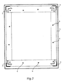
- figure 1 shows a lateral view of the container of the preferred embodiment of the electromechanical system according to the invention;
- figure 2 is a top view of the container of figure 1;
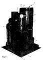
- figure 3 is a first perspective view of the hindering assembly of the preferred embodiment of the electromechanical system according to the invention;
- figure 4 shows a second perspective view of the hindering assembly of figure 3;
- figure 5 shows a top schematic view of the hindering assembly of figure 3;
- figure 6 shows a lateral view of the hindering element of the hindering element of figure 3; and
- figure 7 is a top view of the hindering element of figure 6.
-
- In the following specification, the same reference numbers will be used for the same elements in the various figures.
- The electromechanical system according to the invention comprises a container and a hindering assembly, the preferred embodiment of the electromechanical system is shown in the figures, among which figures 1 and 2 show the
container 1 and figures 3 - 7 show the hinderingassembly 2.Container 1, preferably comprised of metal, acts as formwork for burying the system and as housing frame of the hinderingassembly 2. Thecontainer 1 can be preferably comprised of iron, plastic reinforced by fibre glass, stainless steel, concrete, stone, cast iron. - Making reference to figures 1 and 2, it can be noted that the
container 1 is provided with conical profiled self-centring guides 3, in such a way to allow the proper positioning of the hinderingassembly 2 to fix the same to thecontainer 1. Particularly, making also reference to figures 3 - 5, the hinderingassembly 2 comprises aplanar base 4, provided withholes 5 that, in the fixing position of the hinderingassembly 2 to thecontainer 1, are faced to correspondingholes 6 of thecontainer 1, in such a way that the coupling can be made by screws, not shown. Advantageously, the screwing and unscrewing of the screws occurs by a suitable magnetic key: for example, in case of failure or maintenance, extraction of the hinderingassembly 2 from thecontainer 1 requires less than 10 minutes, also thanks to the fact that all the electrical connections of the components of the hinderingassembly 2 to the fixed networks or devices are realised with connectors, preferably IP68 connectors. It is well evident that thesame container 1 can also house hindering assemblies having different components, provided that the integral coupling means (holes 5) of the latter to thecontainer 1 are the same. - Making particular reference to figures 3 - 5, it can be noted that the
hindering assembly 2 further comprises a cylindrical hinderingassembly 7, actuated by aoleodynamic motor 8, in such a way to be movable between a first lower position, as represented in the figures, substantially buried under the road level, and a second upper position, substantially outside the road level. Preferably, the hinderingelement 7 is singularly removable from the hinderingassembly 2, thus being interchangeable. The hinderingassembly 2 comprises apump 9, for draining the water eventually infiltrated in the electromechanical system, and anelectric unit 10 to control all the components of the electromechanical system. - Making also reference to figures 6 and 7, the cylindrical hindering
element 7 telescopically slides outside asquare section guide 11, along whichcorresponding wheels 13 rotate, coupled with the hinderingelement 7. The cylindrical hinderingelement 7, both in the first lower position and in the second upper position interacts with elastic means, preferablysprings 14 coupled withrods 15, along each one acorresponding slider 16 slides integral with thehindering element 7. In the preferred embodiment, the hinderingassembly 2 comprises tworods 15. Elastic means should reduce the stop speed of the cylindrical hinderingelement 7 in its first and second positions, storing kinetic energy that will be used again to give a bigger starting acceleration to the movement of the hinderingelement 7, thus reducing the operation times of the system. In case of lack of automatic supply by gravity within the container. Particularly, the operation of the cylindrical hinderingelement 7 can occur by a reversible motoriduttore, suitable to automatically lower the hindering element in case of lack of supply. - Instead of the sliding system shown in figures 6 and 7, profiled guides 12, preferably integral with the
planar base 4 can be outside the hinderingelement 7, to which thewheels 13 are coupled, slidable along theguides 12. - Particularly,
motor 8 is realised in an enbloc structure, also comprising the tank, the pump and the valves of the circuit of the hydraulic oil.Motor 8 preferably has a power of about 1.5 kW. The circuit of the hydraulic oil is protected by a collection system that, in the preferred embodiment, comprises atank 17; in this way, in case of possible losses, the risk of environmental pollution is substantially prevented. - Particularly,
electric unit 10 can control the limit positions that preferably can be adjusted by the software. In this way every installation mistaken can be re-regulated at the end of the installation: the above allows a perfect co-planarity of the cylindrical hinderingelement 7 with the road level, when in the first lower position. Preferably, the operation of the cylindrical hinderingelement 7 is of the counter-reaction loop vectorial type, allowing defining the optimum acceleration and deceleration curves for the applied load. Further, it is possible also to independently adjust by software the operative speed for the ascent and the descent. Since the characteristic curves are pre-defined, theelectric unit 10 can automatically detect every unexpected variation due to mechanical problems, such as obstructions or anomalous overcharges. - Rainwater is collected within a first tank 18, integrally coupled with the cylindrical hindering
element 7, and is canalised and stored within a secondbigger tank 19, shown in figure 1, provided in a double bottom of thecontainer 1. A sensor detects the presence of water and operates thepump 9 for the forced scavenging. - A special sensor - heater system detects the temperature within the
container 1, preventing the creation of ice about the cylindrical hinderingelement 7, that could prevent the motion, and in the discharge circuit of the rainwater, thus assuring the perfect functionality of thepump 9 even with very low temperatures. - The
electric unit 10, that during the standard operation is integrally coupled with theplanar base 4 buried along with thecontainer 1, could be subjected to infiltration of humidity and to temperature jumps. In order to avoid inconvenient, theelectric unit 10 is preferably closed within a sealed container, which is filled with inert gas. Further, the inner temperature is constantly maintained at a constant value by a sensor and a special heater. - The
electric unit 10, preferably comprising a programmable logic controller or PLC, can also control the presence of humidity within thecontainer 1 and/or in the hinderingelement 7, thus activating: particular devices preventing the formation of condense; a correct circulation of the air (for example by pressure switches verifying the correct forced circulation of the air); and a series of filters for cleaning air entering within the electromechanical system to cool it. The air circulation control system can, for example, detect anomalous depressions indicating a malfunctioning of the cooling system of a dirty filter. - Particularly,
electric unit 10 can manage all the exercise and alarm functions and is preferably connected by modem, cable, or radio channel, to a remote station for the off-line or on-line signalling of the system state. The connection with the remote station is possible either upon request of theelectric unit 10, on the basis of pre-set parameters, or upon request of the remote station. Every parameter and/or activity of theelectric unit 10 can be verified in real time by the remote station. Theelectric unit 10 preferably has an inner memory able to memorise the identificative alphanumerical codes of users authorised to the access to the area controlled by the electromechanical system of vehicular hindering. Alternatively, theelectric unit 10 can interrogate a file provided in the remote station and containing a list of alphanumerical codes identifying authorised users. In this way, theelectric unit 10 can automatically operate the cylindrical hinderingelement 7, for example following the recognition of a code transmitted by a transponder mounted on the vehicle. All the operative parameters of theelectric unit 10, as well as the software, can be updated in every moment, preferably from the remote station. Advantageously, theelectric unit 10 comprises an emergency feeding system, provided with reserve battery. - Particularly, in the preferred embodiment of the system according to the invention, the
electric unit 10 carries out the following functions and controls: switching on of the flashinglights 20, provided above the cylindrical hinderingelement 7; acoustic emission, for example by double intermittent and continuous bell, as warning of the movement of the cylindrical hinderingelement 7; control of a two or three outer road lights, as warning to the drivers (and from which it can be extracted the air to be circulated in the electromechanical system); control of effractions, on the basis of a alarm system and a siren, with contemporaneous alarm communication transmitted to the remote station; revealing shocks and violations, control of the water level in thesecond tank 19, with possible start of thepump 9; control of the hydraulic oil circuit, revealing the level and the temperature of the oil; control of the presence of hydraulic oil in thetank 17; managing a modem; managing a radio apparatus for the communication with a transponder. - Furthermore, the
electric unit 10 can also control the carrying out of multi media performances, being in this case preferably provided with a computer. - In fact, usual lamps of the light can be replaced by a LED variable message panel that, beside visualising the lights (red, green and eventually yellow), is able to show a real time warning variable message. For example, it is possible to inform the users of particular situations and/or diffusing advertising messages.
- Furthermore, traditional acoustic alarm can be replaced by a bi-directional audio digital channel (I/O or Inlet/Outlet): the user can communicate with an assistance central or can ask informative or useful services, while the audio exit can be used to diffuse any other kind of message, as well as a sound during its operation.
- Still, in the outer light that can be provided in the electromechanical system, or in another suitable position, one or more cameras can be installed, that are useful to control the system from a central area.
- Furthermore, a keyboard on the light can allow to the users to require a specific assistance at a determined service or emergency centre.
- The connection between a user and a service centre can thus use a graphic display, or an I/O audio channel to speak, a visual connection by camera, and/or a keyboard to select the centre providing the required service.
- The electromechanical hindering system according to the invention can also be provided with some connection devices, beside the modem.
- Particularly, the system can include an infrared gate or IrDA, able to establish a connection with other local devices. For example, an occasional user not provided with an authorised transponder can pass through the gate controlled by the system according to the invention, using the cellular phone. Particularly, it is possible to ask the authorisation to the passage by SMS, WAP or other, to pay a charged payment on the SIM-card or WAP by e-commerce procedures, and be "recognised" by the connection IrDA between the cellular phone and the relevant gate of the system according to the invention. In this way, the cellular phone is read by the network as a kind of transponder with activation upon request. Another application of the IrDA gate is the connection with a local PC, for example for diagnosis, control and/or maintenance purposes of the electromechanical hindering system, without the need of opening the electromechanical system.
- Still, the system can comprise a standard serial gate allowing an emergency back-up connection, by an analogic modem or GSM, GPRS, with a control or safety centre.
- Furthermore, the system can comprise a fast internet connection ADSL. This connection can be used for the multi media performances (audio, video), for providing services (for example, information provided to the user of advertising), and the remote control of the electromechanical hindering system (that is also possible, in case of emergency, by the GSM-GPRS). The electromechanical hindering system has an IP address in the Internet, and can thus be reached by every services provider in the network. Therefore, it is also possible to configure the system according to the invention as a real PC in a LAN, MAN, WAN or Wireless network. The same network can be shared by more than one service providers (for example: an advertising provider, a tourist information service centre, police central to control the access). The standard password and user-id technologies, that are standard in the Internet world, allow the contemporaneous access of more than one service providers, without any conflict. In case it is necessary a more performing connection (of the CDN or LAN kind), the hindering system can be provided with a 10 Mbs standard ethernet gate. The internet connection also allows to make a diagnosis and control service of the hindering system directly from an assistance remote centre.
- The present invention has been described for illustrative but not limitative purposes, according to its preferred embodiments, but it is to be understood that modifications and/or changes can be introduced by those skilled in the art without departing from the relevant scope as defined in the enclosed claims.
Claims (29)
- Electromechanical system for hindering vehicular traffic comprising a hindering assembly (2) including a hindering system (7) movable between a first lower position and a second upper position, characterised in that it comprises a container (1), suitable to house the hindering assembly (2), and guide means (3) suitable to guide the positioning of the hindering assembly (2) for fixing the container (1).
- System according to claim 1, characterised in that said guide means can comprise self centring guides (3).
- System according to claim 2, characterised in that said self centring guides (3) have a conical profile.
- System according to claim 2 or 3, characterised in that said self centring guides (3) are integrally coupled with the container (1).
- System according to one of the preceding claims, characterised in that the hindering assembly (2) comprises electromechanical means (8) for operating the hindering element (7).
- System according to claim 5, characterised in that the hindering element (7) interacts with elastic means (14), when it is in the first lower position and/or the second upper position.
- System according to claim 6, characterised in that said elastic means (14) are coupled with further guide means (15), integral with the hindering assembly (2), along which at least a sliding element (16) slides, integral with the hindering element (7).
- System according to claim 7, characterised in that said elastic means comprises at least a spring (14) and said further guide means comprise at least one rod (15)
- System according to claim 8, characterised in that said further guide means comprises four rods (15).
- System according to each one of the claims 6 - 9, characterised in that said elastic means (14) can be within the hindering element (7).
- System according to each one of the claims 5 - 10, characterised in that said operation electromechanical means comprises an oleodynamic motor (8).
- System according to claim 11, characterised in that the hindering assembly (2) comprises a collection system for the leakage of hydraulic oil from the circuit of the oleodynamic motor (8).
- System according to claim 12, characterised in that said collection system for the leakage of hydraulic oil comprises a vessel (17).
- System according to each one of the claims 5 - 13, characterised in that said operation electromechanical means comprises a direct current motor and a corresponding reduction unit.
- System according to each one of the claims 5 - 14, characterised in that said operation electromechanical means comprises a alternate current motor and a corresponding reduction unit.
- System according to each one of the claims 5 - 15, characterised in that it also comprises sensing means for revealing the presence of metallic masses close to the system.
- System according to claim 16, characterised in that said sensing means for revealing the presence of metallic masses comprises at least a magnetic turn.
- System according to each one of the preceding claims, characterised in that the hindering element (7) is telescopically coupled with a guide element (11) by sliding means (12, 13).
- System according to claim 18, characterised in that said sliding means comprises at least a profiled guide (12), integral with the guide element (11), along which a corresponding wheel (13) rotates, said wheel being coupled with the hindering element (7).
- System according to each one of the claims 5 - 17, characterised in that hindering element (7) is movable between a first lower position and a second upper position by sliding means (12, 13) outside the hindering system (7).
- System according to claim 20, characterised in that said sliding means comprises at least a profiled guide (12), integral with the guide element (11), along which a corresponding wheel (13) rotates, said wheel being coupled with the hindering element (7).
- System according to each one of the preceding claims, characterised in that it further comprises a pump (9) and at least a reservoir (18, 19), suitable to collect liquids, the pump (9) being suitable to evacuate outward the container (1) the liquids collected within said at least one reservoir (19).
- System according to claim 22, characterised in that the system comprises a first reservoir (18), integral with the hindering element (7), and a second reservoir (19), integral with the container (1), a hydraulic circuit connecting the first reservoir (18) with the second reservoir (19)..
- System according to claim 22 or 23, characterised in that comprises a sensor revealing the presence of liquid in at least of said reservoirs (18, 19).
- System according to each one of the preceding claims, characterised in that it further comprises a thermal sensor and a heating device, respectively for revealing the temperature and the heating of the hindering element (7).
- System according to each one of the preceding claims, characterised in that it further comprises a control and managing electric unit (10).
- System according to claim 26, characterised in that said electric unit (10) is closed within a sealed housing, filled with dry inert gas.
- System according to claim 26 or 27, characterised in that the electric unit (10) comprises a further thermal sensor element and a further heating element, respectively for revealing the temperature and the heating of the electric unit (10).
- System according to each one of the claims 26 - 28, characterised in that the electric unit (10) also comprises a modem and/or radio communication means.
Applications Claiming Priority (2)
| Application Number | Priority Date | Filing Date | Title |
|---|---|---|---|
| IT2001RM000109U ITRM20010109U1 (en) | 2001-05-30 | 2001-05-30 | ELECTROMECHANICAL SYSTEM FOR DISSUASION OF VEHICLE TRAFFIC. |
| ITRM20010109 | 2001-05-30 |
Publications (2)
| Publication Number | Publication Date |
|---|---|
| EP1270821A2 true EP1270821A2 (en) | 2003-01-02 |
| EP1270821A3 EP1270821A3 (en) | 2005-11-30 |
Family
ID=11455284
Family Applications (1)
| Application Number | Title | Priority Date | Filing Date |
|---|---|---|---|
| EP02425344A Withdrawn EP1270821A3 (en) | 2001-05-30 | 2002-05-29 | Retractable bollard |
Country Status (2)
| Country | Link |
|---|---|
| EP (1) | EP1270821A3 (en) |
| IT (1) | ITRM20010109U1 (en) |
Cited By (2)
| Publication number | Priority date | Publication date | Assignee | Title |
|---|---|---|---|---|
| CN109147065A (en) * | 2017-06-28 | 2019-01-04 | 西安东方信远电动车有限公司 | public parking charging system |
| DE102018121060A1 (en) * | 2018-08-29 | 2020-03-05 | Thomas Wiedermann | Device for charging at least one battery of an at least partially powered vehicle, in particular land vehicle, a method and its use |
Citations (4)
| Publication number | Priority date | Publication date | Assignee | Title |
|---|---|---|---|---|
| US4919563A (en) * | 1989-08-14 | 1990-04-24 | Stice David L | Vehicle parking or passageway security barrier |
| FR2686633A1 (en) * | 1992-01-29 | 1993-07-30 | Bonis Francoise | Retractable obstacle, especially for blocking the passage and/or parking of vehicles |
| FR2779753A1 (en) * | 1998-06-12 | 1999-12-17 | Amco | Motorized retractable road or access way blocking device |
| FR2847279A1 (en) * | 2002-11-19 | 2004-05-21 | Alain Fouassier | Protected zones access reserving device, e.g. parking area, for the disabled has photovoltaic cells protected by transparent wall for battery charger, receiver to permit withdrawal of terminal based on information from transmitter |
-
2001
- 2001-05-30 IT IT2001RM000109U patent/ITRM20010109U1/en unknown
-
2002
- 2002-05-29 EP EP02425344A patent/EP1270821A3/en not_active Withdrawn
Patent Citations (4)
| Publication number | Priority date | Publication date | Assignee | Title |
|---|---|---|---|---|
| US4919563A (en) * | 1989-08-14 | 1990-04-24 | Stice David L | Vehicle parking or passageway security barrier |
| FR2686633A1 (en) * | 1992-01-29 | 1993-07-30 | Bonis Francoise | Retractable obstacle, especially for blocking the passage and/or parking of vehicles |
| FR2779753A1 (en) * | 1998-06-12 | 1999-12-17 | Amco | Motorized retractable road or access way blocking device |
| FR2847279A1 (en) * | 2002-11-19 | 2004-05-21 | Alain Fouassier | Protected zones access reserving device, e.g. parking area, for the disabled has photovoltaic cells protected by transparent wall for battery charger, receiver to permit withdrawal of terminal based on information from transmitter |
Cited By (3)
| Publication number | Priority date | Publication date | Assignee | Title |
|---|---|---|---|---|
| CN109147065A (en) * | 2017-06-28 | 2019-01-04 | 西安东方信远电动车有限公司 | public parking charging system |
| CN109147065B (en) * | 2017-06-28 | 2024-01-30 | 西安东方信远电动车有限公司 | Public parking charging system |
| DE102018121060A1 (en) * | 2018-08-29 | 2020-03-05 | Thomas Wiedermann | Device for charging at least one battery of an at least partially powered vehicle, in particular land vehicle, a method and its use |
Also Published As
| Publication number | Publication date |
|---|---|
| ITRM20010109V0 (en) | 2001-05-30 |
| ITRM20010109U1 (en) | 2002-11-30 |
| EP1270821A3 (en) | 2005-11-30 |
Similar Documents
| Publication | Publication Date | Title |
|---|---|---|
| US10653014B2 (en) | Systems and methods for an intermediate device structure | |
| WO2021105928A1 (en) | A vehicle charging device and system | |
| JP2023109804A (en) | Device, system and usage for connecting electric vehicle with electrical network | |
| DE102009024721A1 (en) | Local charging station for charging storage battery of e.g. electrical passenger car, has plug-in module provided for power connector, where power is supplied from station via existing supply points of public infrastructures | |
| CA2648972A1 (en) | System and method for improved electric cars and/or electric car batteries and/or improved infrastructures for recharging electric cars | |
| US11701977B2 (en) | Kerbside vehicle charger | |
| KR101537753B1 (en) | Unmanned parking fee calculating apparatus | |
| WO2014014331A1 (en) | Electronic system for authorising and searching for parking spaces | |
| US11215958B1 (en) | Automated systems for recreational vehicle parking facility | |
| EP2618450A1 (en) | Lighting and communication device for ultra-wide band networks | |
| EP1270821A2 (en) | Retractable bollard | |
| CN212453872U (en) | Multifunctional rod integrated rod piece | |
| CN111028538A (en) | Intelligent parking system and method | |
| US6696977B2 (en) | Automatic gate control system for freeway interchanges | |
| FR2659995A1 (en) | Motorised telescopic road bollard | |
| CN112396860B (en) | Safety warning method | |
| KR102095166B1 (en) | Monitoring system of blocking apparatus for stream entry route | |
| CN110782683A (en) | Traffic signal lamp capable of automatically controlling and adjusting time | |
| CN217714269U (en) | Traffic acquisition probe convenient to dismantle | |
| CN215212634U (en) | Electronic monitoring equipment for road safety | |
| FI112000B (en) | parking Payment System | |
| EP1650350B1 (en) | Automatic transit-dissuading column actuated hydraulically | |
| CN207106696U (en) | Patrol is hired a car robot | |
| JP3244881U (en) | Sensing Device of Intelligent Parking Management System | |
| KR102401502B1 (en) | Parking management and crime response system using smart pole |
Legal Events
| Date | Code | Title | Description |
|---|---|---|---|
| PUAI | Public reference made under article 153(3) epc to a published international application that has entered the european phase |
Free format text: ORIGINAL CODE: 0009012 |
|
| AK | Designated contracting states |
Kind code of ref document: A2 Designated state(s): AT BE CH CY DE DK ES FI FR GB GR IE IT LI LU MC NL PT SE TR |
|
| AX | Request for extension of the european patent |
Free format text: AL;LT;LV;MK;RO;SI |
|
| PUAL | Search report despatched |
Free format text: ORIGINAL CODE: 0009013 |
|
| AK | Designated contracting states |
Kind code of ref document: A3 Designated state(s): AT BE CH CY DE DK ES FI FR GB GR IE IT LI LU MC NL PT SE TR |
|
| AX | Request for extension of the european patent |
Extension state: AL LT LV MK RO SI |
|
| AKX | Designation fees paid | ||
| REG | Reference to a national code |
Ref country code: DE Ref legal event code: 8566 |
|
| STAA | Information on the status of an ep patent application or granted ep patent |
Free format text: STATUS: THE APPLICATION IS DEEMED TO BE WITHDRAWN |
|
| 18D | Application deemed to be withdrawn |
Effective date: 20060601 |