EP1270261A2 - Verfahren zum Einlegen von zumindest einem Leseband in Buchblocks sowie Vorrichtung zur Durchführung des Verfahrens - Google Patents
Verfahren zum Einlegen von zumindest einem Leseband in Buchblocks sowie Vorrichtung zur Durchführung des Verfahrens Download PDFInfo
- Publication number
- EP1270261A2 EP1270261A2 EP02405513A EP02405513A EP1270261A2 EP 1270261 A2 EP1270261 A2 EP 1270261A2 EP 02405513 A EP02405513 A EP 02405513A EP 02405513 A EP02405513 A EP 02405513A EP 1270261 A2 EP1270261 A2 EP 1270261A2
- Authority
- EP
- European Patent Office
- Prior art keywords
- guide
- book
- book block
- conveying direction
- reading tape
- Prior art date
- Legal status (The legal status is an assumption and is not a legal conclusion. Google has not performed a legal analysis and makes no representation as to the accuracy of the status listed.)
- Granted
Links
- 238000000034 method Methods 0.000 title claims abstract description 48
- 238000005520 cutting process Methods 0.000 claims description 19
- 238000003466 welding Methods 0.000 claims description 9
- 238000000465 moulding Methods 0.000 claims description 6
- 238000007664 blowing Methods 0.000 claims description 4
- 230000001419 dependent effect Effects 0.000 claims description 3
- 239000012209 synthetic fiber Substances 0.000 claims description 2
- 229920002994 synthetic fiber Polymers 0.000 claims description 2
- 238000000926 separation method Methods 0.000 claims 1
- 238000003780 insertion Methods 0.000 abstract description 4
- 230000037431 insertion Effects 0.000 abstract description 4
- 239000003550 marker Substances 0.000 abstract 1
- 238000004519 manufacturing process Methods 0.000 description 2
- 238000012986 modification Methods 0.000 description 2
- 230000004048 modification Effects 0.000 description 2
- 238000003860 storage Methods 0.000 description 2
- 239000004753 textile Substances 0.000 description 2
- 238000010276 construction Methods 0.000 description 1
- 230000000694 effects Effects 0.000 description 1
- 238000000605 extraction Methods 0.000 description 1
- 239000012467 final product Substances 0.000 description 1
- 238000000227 grinding Methods 0.000 description 1
- 238000009434 installation Methods 0.000 description 1
- 238000012423 maintenance Methods 0.000 description 1
- 238000010408 sweeping Methods 0.000 description 1
- 238000011144 upstream manufacturing Methods 0.000 description 1
Images

Classifications
-
- B—PERFORMING OPERATIONS; TRANSPORTING
- B42—BOOKBINDING; ALBUMS; FILES; SPECIAL PRINTED MATTER
- B42C—BOOKBINDING
- B42C9/00—Applying glue or adhesive peculiar to bookbinding
- B42C9/02—Applying glue or adhesive peculiar to bookbinding for securing back linings, strips, ribbons or headbands
- B42C9/025—Applying glue or adhesive peculiar to bookbinding for securing back linings, strips, ribbons or headbands for securing bookmarkers
Definitions
- the invention relates to a method for inserting at least a reading book in book blocks according to the preamble of the claim 1 and an apparatus for performing the method according to the preamble of claim 14.
- reading or provide one-note tapes that enable the reader to by inserting a certain one between two pages of the book To mark the spot of the book.
- You are at the top of the Book block spine inside the cover on the book block spine attached.
- Such reading tapes are chosen in length so that the free end of the book block foot side a piece protrudes so that the reader can grab the reading tape there and that Can open the book on the marked page.
- the free end of a reading book do not hang out below the bottom of the book block, but instead some pages of the book with the free end in the book block be folded back.
- the book block with the book block spine is transported seated on a conveyor belt and divided into two partial blocks by means of a dividing device, between which a wedge-shaped gap is formed.
- the reading tape is then inserted into this wedge-shaped gap in such a way that it protrudes a bit both over the book block head side and over the book block foot side.
- the reading tape is cut off in the area of the book block foot so that the free end protrudes a bit.
- the free end of the reading tape is applied to the book block using compressed air and folded back into the book block using a folding device.
- the end of the reading tape protruding from the book block head is turned over to the outside of the back of the book block by means of a turning device and glued there.
- a method is carried out in a clocked manner and is complex and expensive due to the separate folding step.
- Known devices for performing this method require a high level of maintenance and require a relatively large amount of installation space.
- a clocked production process also places high demands on the accuracy of the conveyor drives and their control.
- the book blocks are moved one behind the other at a minimum distance continuously by a conveyor belt. In this method, too, the reading tape is first inserted into the wedge-shaped gap of a divided book block, the reading tape being fed in the division plane.
- the inserted reading tape is cut and folded in the gaps between the book blocks by means of clocked cutting and gripping devices.
- this method it is disadvantageous that although the drive devices for the book blocks do not have to operate in a clocked manner, it is necessary to allow the cutting and gripping devices to engage in the gaps between the book blocks in a clocked manner. With this method, too, the free end of the reading tape is folded back only after the reading tape has been inserted into the book block.
- the object of the invention is to provide a method for inserting specify at least one reading book in book blocks, which is simple and inexpensive to carry out and easy to different Book formats are customizable. Furthermore, it is a The object of the invention is a device for performing the method indicate which is fail-safe and simple is constructed.
- the object is achieved by a method for insertion solved at least one book in book blocks, the Reading tape has a fastening end and a free end and the book block by means of a conveyor along a Direction of conveyance is moved, the book block by means of a Divider device into at least two outer sub-blocks and one inner sub-block is divided, the reading tape with a predetermined Length across the conveying direction in the barrel of the inner Subblocks is brought, the reading tape in the area of his Attachment end on one side immediately adjacent to the barrel of the inner sub-block releasably attached by a holding device is held and otherwise directly adjacent to Running the inner block by means of a guide device form-fitting and with regard to the longitudinal extent of the reading tape is loosely guided, the middle block with one in the conveying direction front free edge meets the reading tape and this detected so that it is the holding and Guiding equipment happens to be drawn into the book block and after the book block passes the holding and guiding devices has released, the reading tape held releasably
- the book block can advantageously be conveyed by means of the conveyor be moved continuously, making a special effective operation is ensured.
- An inventive device for performing the method has a conveyor for transporting book blocks in a conveying direction and a dividing device for Divide the book block into at least two outer sub-blocks and an inner sub-block, wherein the divider means a guide device for the inner block in the conveying direction is subordinate, the device according to the invention has a holding device and a guide device by means of which a reading tape transverse to the conveying direction in the course of the inner Sub-block 103 is durable and the holding device after the passage of the sub-block through the guide device releasable is.
- Such a device according to the invention has only a few mechanically moving parts and is simple in construction and characterized by high operational reliability.
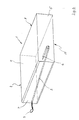
- the result of the method according to the invention is a book block 1, in which a textile reading tape 2 is inserted and folded (Fig. 4).
- the textile reading tape 2 has a fastening end 3 on, which protrudes a bit beyond a book block head 4.
- Book block 1 On one of the book block head 4 opposite Book block foot 5 is the reading tape 2 with its free end 6 some pages of the book block folded back into the book block arranged.
- Book block 1 also has one Book block spine 7 on, in the area of which the single sheets of Book block are bound. Opposite the book block spine 7 the book block 1 has a book block front 8.
- the book block 1 is from a first free outside 9 and a second free outside 10 limited.
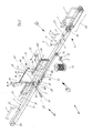
- a device 20 according to the invention has a transport device 21, which as a driven toothed belt 22nd is trained on.
- the conveyor toothed belt 22 extends in a conveying direction 23 and runs on deflection rollers 24.
- the Conveyor toothed belt 22 has an upper run 25 and a lower run 26, the upper run 25 being driven in the conveying direction 23 is.
- the conveyor toothed belt 22 has at regular intervals Driving webs 27 arranged transversely to the belt, the distance between them is larger than the largest book format to be processed.
- the conveying direction 23 of the transport device 21 is a single-stroke device 28 upstream, which works as a clocked conveyor belt is formed and book blocks 1 on the book block spine 7 carries standing and this clocked the transport device 21 supplies that the book blocks 1 each between two carrier webs 27 of the continuously rotating conveyor belt 22 arrive.
- the book blocks 1 are on the book block spine 7 standing vertically on the transport device 21 pass, the book block foot 5 of each book block 1 points in the conveying direction 23.
- the corner area between the Book block spine 7 and the book block head side 4 is the book block 1 with the book block head side 4 on one of the carrier bars 27 on.
- Preferably over the entire longitudinal extent of the transport device 21 are slightly above the upper run 25 spaced parallel guide elements 30 e.g.
- the divider device 32 has two vertically arranged dividing blades 33.
- the divider blades 33 are essentially flat-plate-shaped and provided with sharpened tips 34, which are made of bevel cuts result and point against the conveying direction 23. Between the divider blades 33, a vertical guide gap 35 is formed.
- the guide device 40 In the conveying direction 23 immediately following the dividing blades 33 is a guide device in alignment with the divider device 32 40 arranged.
- the guide device 40 has a first one Guide beam 41 and a second guide beam 42, each are flat plate-shaped and slightly spaced parallel to each other forming a vertical guide gap 43 are arranged vertically.
- the first guide cheek 41 and the second Guide cheek 42 are of the same shape and each have a first upper long horizontal boundary edge 44, one second lower short, slightly above the take-along bars horizontal boundary edge 45 and a first front short vertical boundary edge 46 and a second rear edge long vertical boundary edge 47.
- the second vertical Boundary edge 45 runs parallel to the conveying direction 23 approximately in the middle with respect to the upper run 25 of the conveyor toothed belt 22 a bit above the upper run 25.
- the vertical The extension of the guide cheeks 41, 42 is selected in such a way that the first horizontal boundary edge 44 on a vertical Level above the book block front 8 of the book block 1 is arranged with the largest landscape format to be processed.
- the first vertical boundary edge 46 of the guide cheeks 41, 42 points towards the inlet area 31 of the device 20 and is designed as a sharpened edge.
- the second vertical boundary 47 of the guide cheeks 41, 42 points in the direction of Conveying direction 23 and extends from the first horizontal Boundary edge 44 to the second horizontal boundary edge 45.
- the connecting edge between the first vertical short, preferably designed as a cutting edge 46 and the second short horizontal boundary edge 45 of the guide cheeks 41, 42 is in each case as an oblique boundary edge 48 trained, which also sharpened Cutting is executed.
- the guide device 40 is arranged relative to the divider device 32 such that the vertical gap 35 of the divider device 32 preferably immediately in the vertical guide gap 43 of the guide device 40 flows.
- the divider blades 33 are advantageously in the area of the inclined boundary edges 48 on the guide cheeks 41, 42 attached.
- the guide gap 35 thus goes into the guide gap 43 about that there are no edges that abut Effect book block pages and thus hinder the transport could.
- the guide cheeks 41, 42 are in the region of their first horizontal Boundary edges 44 at one above the guide device 40 arranged frame (not shown) "hanging" attached.
- a take-off / cutting device from the transport device 21 50 arranged in parallel to the conveying direction 23 in a direction 51 is oscillating back and forth.
- the Trigger / cutter 50 has guiding, gripping and Cutting means for the reading tape wound on a roll 52 2 on.
- the reading tape 2 stored on the roll 52 is preferred via a welding device 53 and possibly via deflection rollers 54 performed, the welding device 53 in Area of the later interfaces of the reading tape 2, the synthetic fibers of the reading tape 2 welded in areas, so that after the cutting of the reading tape 2 prevents fraying of the ends is.
- a feed device (not shown) is arranged, which has a feed stamp 60 which is in one direction 61 can be moved oscillating transversely to the conveying direction 23.
- the Feed stamp 60 has an elongated, rod-shaped spatial shape an end 62 facing the guide device 40, at which an Gripping device (not shown) for the free end 3 'of the reading tape 2 is arranged.
- Corresponding holes 65 and 66 introduced, which are mutually in the 61 direction.
- the first molding hole is 65 in the first guide cheek 41, which faces the feed stamp 60 is arranged and acts as a guide for the Reading tape 2.
- the second form hole 66 is in the second guide cheek 42, which is facing away from the feed stamp 60, arranged and is part of a holding device 70a for the reading tape 2.
- the second guide cheek 42 is in the area of its second vertical Limiting edge 47 forked in cross section with a first Edge edge web 67 and a second edge edge web 68 are formed (Fig. 2), wherein the second shaped hole 66 in the second marginal edge web 68 is arranged.
- the first edge edge web 67 has a third molding hole corresponding to the molding holes 65, 66 (not shown).
- Limit the edge ridges 67, 68 one over the entire vertical height of the second guide beam 42 extending slot recess 69 in which a clamping lever 70, which is part of the holding device 70a, about an axis 71 is pivotally mounted.
- the axis 71 is transverse to the conveying direction 23 arranged approximately at half the vertical height of the guide cheek 42.
- the clamping lever 70 projects above the guide cheek 42 with a free end 72 a piece, the free end 72 a bore 73 for connection to an actuating means, for. B. a pneumatic push / pull cylinder (not shown).
- the clamping lever 70 extends from its free end 72 in the slot recess 69 to just above the second horizontal boundary edge 45 of the guide cheek 42 and has in Region of its lower end 74 to the form holes 65, 66 corresponding return, which is arranged in such a way that in a starting position of the clamping lever 70, the form holes 65, 66 are freely aligned and only by pivoting the clamping lever 70 about the axis 71 of the clamping lever recess 70b in a Can be brought to the free passage through the Form holes 65, 66 interrupt or cover, one of the holes sweeping reading tape 2 is clamped.
- the Clamping lever 70 positioned in its initial position in this way is that it has free passage through the form holes 65, 66 not disabled.
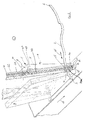
- the form holes 65, 66 in the corner areas of the Leitwangen 41, 42 and the corresponding return of the Clamping levers 70 form a holding / guiding device 70a for the reading tape 2, which with the feed stamp 60 with its free end 3 'can be inserted into the holding / guiding device is so that the free end 3 'of the reading tape is the shape recesses 65, 66, 66a bridging through the guide gap 43 and protrudes a bit from the second guide cheek 42 (see Fig. 2).
- section B (Fig. 1) runs the book block 1 on the divider 32 so that the sharpened tips 34 the book block 1 preferably on the Book block foot 5 either in the area of the book block front 8 or possibly in the area of the book block spine 7 and book block 1 in three sub-blocks, d. H. in a first outer Sub-block 101 a second outer sub-block 102 and one divide between these arranged inner partial block 103, the inner sub-block 103 the vertical gap 35 of the divider 32 passes through and the outer sub-blocks 101, 102 pressed outwards by the dividing blades 33, 34 and on the guide rods 30 are supported.
- the gripping device 62 at the end of the feed stamp 60 detects the free end 3 'of the reading tape 2'. Subsequently the trigger cutter 50 is a bit along move in the direction 51 against the conveying direction 23 and then cut the reading tape 2 to the desired length. Thereupon, the free end 3 of the now cut to length 2 by the free form holes 65, 66 out until it over the guide cheek 42nd protrudes a bit.
- the reading tape is independent cut from the book format to the desired length and can then be fed to the book block as a single volume.
- the length of the reading tape is very wide Freely selectable limits. In extreme cases, even reading tapes that are shorter than the book block format.
- the second reading tape is shared with the Reading tape 2 supplied to the guide device 40 and there as for the reading tape 2 explained inserted in a book block.
- a special one Advantage of this side by side and each reading tape feed units equipped with their own welding device 53 is that the two reading tapes are separate are welded together before they are brought together, so that mutual welding is avoided, like this with the common welding unit used so far may be the case for several reading tapes.
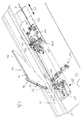
- FIG. 5 only shows the explanation of the variant required parts of the device 20 of FIG. 1 in the area the guide device 40 without showing the divider device 32 and the guide elements 30 and without the representation of Book blocks.
- the trigger / cutting device 50 As already explained above with reference to FIG. 1 the reading tape 2 coming from its storage role after it has penetrated the associated welding device, the trigger / cutting device 50.
- the one shown in Fig. 5 Embodiment comprises the trigger / cutting device as a guide means two in the transverse direction related to the conveying direction the transport device 21 arranged offset with respect to each other Deflection rollers 121, 122 and a pair of these in the conveying direction downstream squeeze rollers 123, 124.
- a gripping means follows the pinch rollers 123, 124 in the form of two jaws, one of which is transverse to the direction of belt travel for gripping the band 2 by an actuator 126 is adjustable.
- the gripping means 125 follows immediately a cutter 127.
- a gripping unit 128 is provided behind the guide device 40, which serves to grip the free front end 3 of the reading tape 2, by means of two jaws 129, 130, of which one movable in the transverse direction with respect to the tape running direction and can be driven by an actuating device 130 is.
- a feed carriage 132 is provided, which extends transversely to the tape running direction and in one direction transversely is oscillating to the tape running direction.
- the feed carriage 132 has an elongated spatial shape with one of the guide devices 40 facing end 133 with which a gripping device with Clamping jaws (not shown) for the free end 3 of the reading tape 2 is arranged. Laterally next to the gripping device (in Fig.
- Blower nozzle 134 On the blowing nozzle 134 is in a manner not shown Control valve device connected to a compressed air source and the blowing nozzle 134 is arranged on the feed carriage 132 in such a way that the air jet generated by it through the form holes 65, 66 runs in the guide device 40.
- the reading tape 2 is operated by an operator deducted from the storage roll to the pulleys 121, 122 out between the pinch rollers 123, 124 and through passed the open gripping means 125, of which the The tape with its free end 3 typically protrudes 2 to 3 cm is left. Then the gripping means 125 is used for fixing of the reading tape 2 activated. Next is the lift carriage 50a activated and towards the feed carriage 132 started, the gripping device in the open State is so that the free end of the tape 3 at the end of the stroke of the lifting slide 50a between the open clamping jaws 129, 130 of the gripping unit 128 comes to rest.
- the method or the device can be both offline and preferably used inline in book production lines.
- the book block sequence does not have to be as with other known methods continuously because each book block is cut to length Reading tape is assigned.
Landscapes
- Basic Packing Technique (AREA)
- Collation Of Sheets And Webs (AREA)
- Auxiliary Devices For And Details Of Packaging Control (AREA)
- Electrically Operated Instructional Devices (AREA)
Abstract
Description
Bei einem weiteren bekannten Verfahren werden die Buchblöcke hintereinander einen Mindestabstand aufweisend kontinuierlich von einem Förderband bewegt. Auch bei diesem Verfahren wird zunächst das Leseband in den keilförmigen Spalt eines geteilten Buchblockes eingelegt, wobei das Leseband in der Teilungsebene zugeführt wird. Anschließend wird mittels getakteten Schneidund Greifvorrichtungen das eingelegte Leseband in den Lücken zwischen den Buchblöcken zugeschnitten und eingefaltet. Bei diesem Verfahren ist es von Nachteil, dass zwar nicht die Antriebseinrichtungen für die Buchblöcke taktend arbeiten müssen, jedoch ist es erforderlich, die Schneid- und Greifeinrichtungen getaktet in die Lücken zwischen den Buchblöcken eingreifen zu lassen. Auch bei diesem Verfahren erfolgt das Zurückfalten des freien Endes des Lesebandes erst nach dem Einlegen des Lesebandes in den Buchblock.
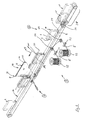
- Fig. 1
- schematisch eine erfindungsgemäße Vorrichtung zum Durchführen des erfindungsgemäßen Verfahrens;
- Fig. 2
- eine perspektivische Detailansicht auf eine Halte-/Führungseinrichtung der erfindungsgemäßen Vorrichtung gemäß Fig. 1 in einer Ausgangslage relativ zu einem Buchblock;
- Fig. 3
- die Halte-/Führungseinrichtung gemäß Fig. 2 während des Einziehvorganges des Lesebandes;
- Fig. 4
- einen Buchblock mit eingelegtem und zurückgefaltetem Leseband als Ergebnis des erfindungsgemäßen Verfahrens;
- Fig. 5
- eine Abwandlung der Vorrichtung von Fig. 1 im Bereich E;
- Fig. 6
- eine erfindungsgemäße Vorrichtung zum Einlegen einer Mehrzahl von Lesebändern.
Claims (51)
- Verfahren zum Einlegen zumindest eines Lesebandes (2) in Buchblocks (1), wobei das Leseband (2) ein Befestigungsende (3) und ein freies Ende (6) aufweist und der Buchblock (1) mittels einer Transporteinrichtung (21) entlang einer Förderrichtung (23) bewegt wird, dadurch gekennzeichnet, dass der Buchblock (1) mittels einer Teilereinrichtung (32) in zumindest zwei äußere Teilblöcke (101, 102) und einen inneren Teilblock (103) geteilt wird,
das Leseband (2) mit einer vorbestimmten Länge quer zur Förderrichtung (23) in den Lauf des inneren Teilblocks (103) gebracht wird, wobei das Leseband (2) im Bereich seines Befestigungsendes (3) einseitig unmittelbar benachbart zum Lauf des inneren Teilblocks (103) mittels einer Halteeinrichtung (66, 70) lösbar befestigt gehalten wird und anderseitig unmittelbar benachbart zum Lauf des inneren Teilblocks (103) mittels einer Führungseinrichtung (65) formschlüssig und bezüglich der Längserstreckung des Lesebands (2) lose geführt wird,
der mittlere Teilblock (103) mit einer in Förderrichtung (23) vorderen freien Kante (106) auf das Leseband (2) trifft und dieses erfasst, so dass es, während der Buchblock die Halte- und Führungseinrichtungen (65, 66, 70) passiert, in den Buchblock (1) eingezogen wird und
nachdem der Buchblock (1) die Halte- und Führungseinrichtungen (65, 66 ,70) passiert hat, das lösbar befestigt gehaltene Leseband (2) freigegeben wird. - Verfahren nach Anspruch 1, dadurch gekennzeichnet, dass der Buchblock (1) mittels der Transporteinrichtung (21) kontinuierlich bewegt wird.
- Verfahren nach einem oder mehreren der vorhergehenden Ansprüche, dadurch gekennzeichnet, dass die äußeren Buchblocks (102, 101) mittels Leitelementen (30) geführt werden.
- Verfahren nach einem oder mehreren der vorhergehenden Ansprüche, dadurch gekennzeichnet, dass die geteilten Teilblöcke (101, 102, 103) nach dem Einlegen des Lesebands (2) durch die Leitelemente (30) wieder zusammengeführt werden.
- Verfahren nach einem oder mehreren der vorhergehenden Ansprüche, dadurch gekennzeichnet, dass die Buchblocks (1) mittels einer Eintakteinrichtung (28) der Transporteinrichtung (21) getaktet zugeführt werden.
- Verfahren nach einem oder mehreren der vorhergehenden Ansprüche, dadurch gekennzeichnet, dass der innere Teilblock (103) nach dem Durchlaufen der Teilereinrichtung (32) einer Leiteinrichtung (40) zugeführt wird.
- Verfahren nach einem oder mehreren der vorhergehenden Ansprüche, dadurch gekennzeichnet, dass die äußeren Teilblöcke (101, 102) während des Einziehens des Lesebands (2) jeweils zwischen einem Leitelement (30) und der Leiteinrichtung (40) geführt werden.
- Verfahren nach einem oder mehreren der vorhergehenden Ansprüche, dadurch gekennzeichnet, dass nach dem Freigeben des Lesebandes (2) mittels einer Zuführeinrichtung ein nächstes Leseband (2) in vorbestimmter Länge der Führungs- und Halteeinrichtung (65, 66, 70) zugeführt wird und das Leseband (2) im Bereich des Befestigungsendes (3) geklemmt gehalten wird.
- Verfahren nach einem oder mehreren der vorhergehenden Ansprüche, dadurch gekennzeichnet, dass das Leseband (2) mittels einer Abzugs-/Schneideeinrichtung (50) von einer Vorratsrolle (52) abgerollt und auf die gewünschte Länge geschnitten wird.
- Verfahren nach einem oder mehreren der vorhergehenden Ansprüche, dadurch gekennzeichnet, dass im Bereich der vorbestimmten Trennstellen des Lesebandes (2) dieses mittels einer Verschweißeinrichtung (53) verschweißt wird.
- Verfahren nach einem oder mehreren der vorhergehenden Ansprüche, dadurch gekennzeichnet, dass die Buchblocks (1) mit ihrer Buchblockfußseite (5) in Förderrichtung (23) weisend bewegt werden, wenn das Leseband (2) im Bereich der Buchblockkopfseite (4) am Buchblockrücken (7) befestigt werden soll.
- Verfahren nach einem oder mehreren der vorhergehenden Ansprüche, dadurch gekennzeichnet, dass die Buchblocks (1) mit ihrer Buchblockkopfseite (4) in Förderrichtung (23) weisend bewegt werden, wenn das Leseband (2) im Bereich der Buchblockfußseite (5) am Buchblockrücken (7) befestigt werden soll.
- Verfahren nach einem oder mehreren der vorhergehenden Ansprüche, dadurch gekennzeichnet, dass die Buchblocks (1) auf dem Buchblockrücken (7) stehend transportiert werden.
- Vorrichtung zum Durchführen des Verfahrens nach einem oder mehreren der Ansprüche 1 bis 13, mit einer Transporteinrichtung (21) zum Transportieren von Buchblöcken (1) in einer Förderrichtung (23) und einer Teilereinrichtung (32) zum Aufteilen des Buchblocks (1) in zumindest zwei äußere Teilblöcke (101, 102) und einen inneren Teilblock (103), wobei der Teilereinrichtung (32) eine Leiteinrichtung (40) für den Teilblock (103) in Förderrichtung (23) nachgeordnet ist, wobei die Vorrichtung (20) eine Halteeinrichtung (66, 70) und eine Führungseinrichtung (65) aufweist, mittels denen ein Leseband (2) quer zur Förderrichtung (23) in den Lauf des Teilblocks (103) haltbar ist und die Halteeinrichtung (66, 70) nach dem Durchlauf des Teilblocks (103) durch die Leiteinrichtung (40) lösbar ist.
- Vorrichtung nach Anspruch 14, dadurch gekennzeichnet, dass die Transporteinrichtung (21) ein kontinuierlich antreibbarer Förderzahnriemen ist, welcher sich in die Förderrichtung (23) erstreckt und auf Umlenkrollen (24) umläuft.
- Vorrichtung nach Anspruch 14 oder 15, dadurch gekennzeichnet, dass der Förderzahnriemen (22) einen Obertrum (25) und einen Untertrum (26) aufweist, wobei der Obertrum (25) in Förderrichtung (23) angetrieben ist.
- Vorrichtung nach einem oder mehreren der Ansprüche 14 bis 16, dadurch gekennzeichnet, dass der Förderzahnriemen (22) in regelmäßigen Abständen angeordnete Mitnahmestege (27) aufweist, deren Abstand größer ist als das größte zu verarbeitende Buchhochformat.
- Vorrichtung nach einem oder mehreren der Ansprüche 14 bis 17, dadurch gekennzeichnet, dass in Förderrichtung (23) der Transporteinrichtung (21) eine Eintakteinrichtung (28) vorgeordnet ist, welche als taktend arbeitendes Förderband ausgebildet ist und die Buchblöcke (1) auf ihrem Buchblockrücken (7) stehend trägt und diese derart getaktet der Transporteinrichtung (21) zuführt, dass die Buchblöcke (1) jeweils zwischen zwei Mitnahmestege (27) des kontinuierlich umlaufenden Förderzahnriemens (22) gelangen.
- Vorrichtung nach einem oder mehreren der Ansprüche 14 bis 18, dadurch gekennzeichnet, dass die Buchblöcke (1) vertikal auf dem Buchblockrücken (7) stehend auf dem Förderzahnriemen (22) angeordnet sind, wobei die Buchblockfußseite eines jeden Buchblocks (1) in Förderrichtung (23) weist.
- Vorrichtung nach einem oder mehreren der Ansprüche 14 bis 19, dadurch gekennzeichnet, dass der Buchblock (1) im Eckbereich zwischen dem Buchblockrücken (7) und der Buchblockkopfseite (4) mit der Buchblockkopfseite (4) an einem der Mitnahmestege (27) anliegt.
- Vorrichtung nach einem oder mehreren der Ansprüche 14 bis 20, dadurch gekennzeichnet, dass etwas oberhalb des Obertrums (25), insbesondere über die gesamte Längserstreckung der Transporteinrichtung (21), beabstandet zueinander parallel verlaufende Leitelemente (30) angeordnet sind, welche ein Umkippen des Buchblocks (1) während des Transports verhindern.
- Vorrichtung nach einem oder mehreren der Ansprüche 14 bis 21, dadurch gekennzeichnet, dass auf einen Einlaufbereich (31) der Transporteinrichtung (21) folgend ein Stück oberhalb den Leitelementen (30) die Teilereinrichtung (32) angeordnet ist.
- Vorrichtung nach einem oder mehreren der Ansprüche 14 bis 22, dadurch gekennzeichnet, dass die Teilereinrichtung (32) zwei Teilerklingen (33) aufweist, wobei die Teilerklingen (33) im wesentlichen flachplattenförmig ausgebildet sind und mit geschärften Spitzen (34) versehen sind, welche entgegen der Förderrichtung (23) weisen, so dass zwischen den Teilerklingen (33) ein vertikaler Spalt (35) ausgebildet ist.
- Vorrichtung nach einem oder mehreren der Ansprüche 14 bis 23, dadurch gekennzeichnet, dass die Leiteinrichtung (40) in Förderrichtung (23) fluchtend zum vertikalen Spalt (35) der Teilereinrichtung (32) angeordnet ist.
- Vorrichtung nach einem oder mehreren der Ansprüche 14 bis 24, dadurch gekennzeichnet, dass die Leiteinrichtung (40) eine erste Leitwange (41) und eine zweite Leitwange (42) aufweist, welche jeweils flachplattenförmig ausgebildet sind und gering beabstandet parallel zueinander einen vertikalen Führungsspalt (43) bildend angeordnet sind.
- Vorrichtung nach einem oder mehreren der Ansprüche 14 bis 25, dadurch gekennzeichnet, dass die erste Leitwange (41) und die zweite Leitwange (42) konturengleich ausgebildet sind und jeweils eine erste horizontale Begrenzungskante (44), eine zweite horizontale Begrenzungskante (45) sowie eine erste vertikale Begrenzungskante (46) und eine zweite vertikale Begrenzungskante (47) aufweisen.
- Vorrichtung nach einem oder mehreren der Ansprüche 14 bis 26, dadurch gekennzeichnet, dass die zweite vertikale Begrenzungskante (45) jeweils parallel zur Förderrichtung (23) etwa quermittig bezüglich des Förderzahnriemens (22) ein Stück oberhalb des Obertrums (25) verläuft.
- Vorrichtung nach einem oder mehreren der Ansprüche 14 bis 27, dadurch gekennzeichnet, dass die vertikale Erstreckung der Leitwangen (41, 42) derart gewählt ist, dass die erste horizontale Begrenzungskante (44) auf einem vertikalen Niveau oberhalb der Buchblockvorderseite (8) des Buchblocks (1) mit dem größten zu verarbeitenden Querformat angeordnet ist.
- Vorrichtung nach einem oder mehreren der Ansprüche 14 bis 28, dadurch gekennzeichnet, dass die erste vertikale Begrenzungskante (46) der Leitwangen (41, 42) in Richtung zum Einlaufbereich (31) der Transporteinrichtung (21) weist und als geschärfte Kante ausgebildet ist.
- Vorrichtung nach einem oder mehreren der Ansprüche 14 bis 29, dadurch gekennzeichnet, dass die zweite vertikale Begrenzungskante (47) der Leitwangen (41, 42) in Richtung der Förderrichtung (23) weist und sich von der ersten horizontalen Begrenzungskante (44) bis zur zweiten horizontalen Begrenzungskante (45) erstreckt.
- Vorrichtung nach einem oder mehreren der Ansprüche 14 bis 30, dadurch gekennzeichnet, dass zwischen der ersten vertikalen Begrenzungskante (46) und der zweiten horizontalen Begrenzungskante (45) der Leitwangen (41, 42) jeweils eine Schrägbegrenzungskante (48) ausgebildet ist, welche als geschärfte Begrenzungskante ausgeführt ist.
- Vorrichtung nach einem oder mehreren der Ansprüche 14 bis 31, dadurch gekennzeichnet, dass die Leiteinrichtung (40) relativ zur Teilereinrichtung (32) derart angeordnet ist, dass der vertikale Spalt (35) der Teilereinrichtung (32) vorzugsweise unmittelbar in den vertikalen Führungsspalt (43) der Leiteinrichtung (40) mündet.
- Vorrichtung nach einem oder mehreren der Ansprüche 9 bis 32, dadurch gekennzeichnet, dass die Teilerklingen (33) im Bereich der Schrägbegrenzungskanten (48) an einer Verstelleinrichtung zum Bewerkstelligen eines formatabhängigen Rückhubs der Abzugs-/Schneideeinrichtung (50) befestigt sind.
- Vorrichtung nach einem oder mehreren der Ansprüche 14 bis 33, dadurch gekennzeichnet, dass die Leitwangen (41, 42) im Bereich ihrer ersten horizontalen Begrenzungskanten (44) an einem oberhalb der Leiteinrichtung (40) angeordneten Rahmengestell hängend befestigt sind.
- Vorrichtung nach einem oder mehreren der Ansprüche 14 bis 34, dadurch gekennzeichnet, dass seitlich benachbart zur Transporteinrichtung (21) separiert von dieser eine Abzugs-/Schneideeinrichtung (50) angeordnet ist, welche parallel zur Förderrichtung (23) in einer Richtung (51) oszillierend hin und her bewegbar ist.
- Vorrichtung nach einem oder mehreren der Ansprüche 14 bis 35, dadurch gekennzeichnet, dass die Abzugs-/Schneideeinrichtung (50) Führungs-, Greif- und Schneidmittel für das auf einer Rolle aufgewickelte Leseband (2) aufweist.
- Vorrichtung nach einem oder mehreren der Ansprüche 14 bis 36, dadurch gekennzeichnet, dass eine Verschweißeinrichtung (53) vorgesehen ist, mit welcher im Bereich der späteren Schnittstellen des Lesebandes (2) die Kunstfasern des Lesebandes bereichsweise verschweißbar sind, so dass nach dem Schneiden des Lesebandes (2) ein Ausfransen der Enden verhindert ist.
- Vorrichtung nach einem oder mehreren der Ansprüche 14 bis 37, dadurch gekennzeichnet, dass über ein in Förderrichtung (23) vorderes Ende (55) der Abzugs-/Schneideeinrichtung (50) ein freies Ende (3') des noch nicht abgelängten Lesebandes (2) ein Stück übersteht.
- Vorrichtung nach einem oder mehreren der Ansprüche 14 bis 38, dadurch gekennzeichnet, dass im Bereich des freien Endes (3') eine Zuführeinrichtung (60, 132) angeordnet ist, die in einer Richtung (61) quer zur Förderrichtung (23) oszillierend bewegbar ist.
- Vorrichtung nach einem oder mehreren der Ansprüche 14 bis 39, dadurch gekennzeichnet, dass die Zuführeinrichtung (60, 132) eine längliche, stabförmige Raumform mit einem der Leiteinrichtung (40) zugewandten Ende (62, 133) hat, an dem eine Greifeinrichtung für das freie Ende (3) des Lesebandes (2) angeordnet ist.
- Vorrichtung nach Anspruch 39 oder 40, dadurch gekennzeichnet, dass in Verlängerung der Zuführeinrichtung (60) im Eckbereich zwischen der zweiten horizontalen Begrenzungskante (45) und der zweiten vertikalen Begrenzungskante (47) in die Leitwangen (41, 42) zum Querschnitt der Zuführeinrichtung (60) korrespondierende Formlöcher (65, 66) eingebracht sind, welche zueinander in der Richtung (61) fluchten, wobei das Formloch (65) als Führungseinrichtung wirkt und das Formloch (66) Teil der Halteeinrichtung (66, 70) ist.
- Vorrichtung nach einem oder mehreren der Ansprüche 14 bis 41, dadurch gekennzeichnet, dass das erste Formloch (65) in der ersten Leitwange (41) angeordnet ist, welche der Führungseinrichtung (60) zugewandt ist.
- Vorrichtung nach einem oder mehreren der Ansprüche 14 bis 42, dadurch gekennzeichnet, dass die Halteeinrichtung (66, 70) das zweite Formloch (66) aufweist, welches in der zweiten Leitwange (42) angeordnet ist, die vom Zuführstempel (60) abgewandt angeordnet ist.
- Vorrichtung nach einem oder mehreren der Ansprüche 14 bis 43, dadurch gekennzeichnet, dass die zweite Leitwange (42) im Bereich ihrer zweiten vertikalen Begrenzungskante (47) im Querschnitt gegabelt mit einem ersten Randkantensteg (67) und einem zweiten Randkantensteg (68) ausgebildet ist, wobei das zweite Formloch (66) im zweiten Randkantensteg (68) angeordnet ist und der erste Randkantensteg (67) ein zu den Formlöchern (65, 66) korrespondierendes drittes Formloch aufweist.
- Vorrichtung nach einem oder mehreren der Ansprüche 14 bis 44, dadurch gekennzeichnet, dass die Randkantenstege (67, 68) eine sich über die gesamte vertikale Höhe der zweiten Leitwange (42) erstreckende Schlitzvertiefung (69) aufweisen, in welcher ein Klemmhebel (70) um eine Achse (71) schwenkbar gelagert ist, wobei der Klemmhebel (70) Teil der Halteeinrichtung (66, 70) ist.
- Vorrichtung nach einem oder mehreren der Ansprüche 14 bis 45, dadurch gekennzeichnet, dass die Achse (71) quer zur Förderrichtung (23) etwa auf halber vertikaler Höhe der Leitwange (42) angeordnet ist.
- Vorrichtung nach einem oder mehreren der Ansprüche 14 bis 46, dadurch gekennzeichnet, dass der Klemmhebel (70) die Leitwange (42) nach oben hin mit einem freien Ende (72) ein Stück überragt, wobei das freie Ende (72) eine Bohrung (73) zum Anschluß an ein Betätigungsmittel, z. B. einen pneumatischen Zug-/Druckzylinder, aufweist.
- Vorrichtung nach einem oder mehreren der Ansprüche 14 bis 47, dadurch gekennzeichnet, dass der Klemmhebel (70) sich von seinem freien Ende (72) in der Schlitzausnehmung (69) bis kurz oberhalb der zweiten horizontalen Begrenzungskante (45) der Leitwange (42) erstreckt und im Bereich seines unteren Endes (74) ein zu den Formlöchern (65, 66) und dem dritten Formloch korrespondierenden Rücksprung aufweist, wobei der Rücksprung im Klemmhebel (70) in einer Ausgangsstellung des Klemmhebels (70) fluchtend zu den Formlöchern (65, 66) und dem dritten Formloch angeordnet ist und durch Verschwenken des Klemmhebels (70) um die Achse (71) in eine Lage gebracht werden kann, die den freien Durchgang durch die Formlöcher (65, 66) unterbricht bzw. abdeckt.
- Vorrichtung nach einem oder mehreren der Ansprüche 14 bis 48, dadurch gekennzeichnet, dass die Formlöcher (65, 66) und das dritte Formloch in den Eckbereichen der Leitwangen (41, 42) sowie der korrespondierende Rücksprung des Klemmhebels (70) eine Klemmfädeleinrichtung für das Leseband (2), welches mit dem Zuführstempel (60) mit seinem freien Ende (3') in die Halte-/Führungseinrichtung (65, 66, 70) einsetzbar ist, so dass das freie Ende (3') des Lesebandes (2) die Formausnehmungen (65, 66) den Führungsspalt (43) quer zur Förderrichtung (23) überbrückend durchgreift und ein Stück über die zweite Leitwange (42) hinausragt.
- Vorrichtung nach einem oder mehreren der Ansprüche 14 bis 49, dadurch gekennzeichnet, dass die Leitelemente (30) im Bereich nach der Leiteinrichtung (40) sich verjüngend ausgebildet sind, so dass der durch die Teilereinrichtung (32) geöffnete Buchblock (1) wieder schließbar ist.
- Vorrichtung nach einem oder mehreren der Ansprüche 39 bis 50, dadurch gekennzeichnet, dass die Zuführeinrichtung (132) eine Blasdüse (134) an dem der Leiteinrichtung (40) zugewandten Ende (133) zum Blasen des freien Endes (3) des Buchbandes (2) durch die Formlöcher (65, 66) aufweist, sobald die Zuführeinrichtung ihre an die Leiteinrichtung (40) angrenzende Stellung eingenommen hat.
Applications Claiming Priority (2)
| Application Number | Priority Date | Filing Date | Title |
|---|---|---|---|
| DE10130209 | 2001-06-22 | ||
| DE10130209A DE10130209B4 (de) | 2001-06-22 | 2001-06-22 | Verfahren zum Einlegen von zumindest einem Leseband in Buchblocks sowie Vorrichtung zur Durchführung des Verfahrens |
Publications (3)
| Publication Number | Publication Date |
|---|---|
| EP1270261A2 true EP1270261A2 (de) | 2003-01-02 |
| EP1270261A3 EP1270261A3 (de) | 2004-01-21 |
| EP1270261B1 EP1270261B1 (de) | 2006-12-27 |
Family
ID=7689118
Family Applications (1)
| Application Number | Title | Priority Date | Filing Date |
|---|---|---|---|
| EP02405513A Expired - Lifetime EP1270261B1 (de) | 2001-06-22 | 2002-06-20 | Verfahren zum Einlegen von zumindest einem Leseband in Buchblocks sowie Vorrichtung zur Durchführung des Verfahrens |
Country Status (3)
| Country | Link |
|---|---|
| EP (1) | EP1270261B1 (de) |
| AT (1) | ATE349340T1 (de) |
| DE (2) | DE10130209B4 (de) |
Cited By (2)
| Publication number | Priority date | Publication date | Assignee | Title |
|---|---|---|---|---|
| DE102021110008A1 (de) | 2021-04-20 | 2022-10-20 | Müller Martini Holding AG | Vorrichtung und Verfahren zum Lesebandeinlegen |
| DE102021110007A1 (de) | 2021-04-20 | 2022-10-20 | Müller Martini Holding AG | Vorrichtung und Verfahren zum Lesebandeinlegen |
Citations (1)
| Publication number | Priority date | Publication date | Assignee | Title |
|---|---|---|---|---|
| DE2010074A1 (de) | 1970-03-04 | 1971-09-23 | Sigloch, Walter, 7118 Künzelsau | Vorrichtung zum Einlegen von Zeichenbändern in Buchblöcke |
Family Cites Families (3)
| Publication number | Priority date | Publication date | Assignee | Title |
|---|---|---|---|---|
| CH513006A (fr) * | 1969-07-04 | 1971-09-30 | Hunkeler Ag Jos | Verfahren zum maschinellen Einführen und Befestigen eines Buchzeichens und Maschine zur Durchführung des Verfahrens |
| DE2053648A1 (de) * | 1970-10-31 | 1972-05-04 | Rahdener Maschinenfabrik August Kolbus, 4993 Rahden | Verfahren zum Einlegen von Zeichenban dem in Buchblocks od dgl und Vorrichtung zur Durchfuhrung des Verfahrens |
| DE2436051C2 (de) * | 1974-07-26 | 1981-12-24 | Rudolf 8500 Nürnberg Czech | Vorrichtung zum Einlegen des Zeichenbandes in Buchblöcke |
-
2001
- 2001-06-22 DE DE10130209A patent/DE10130209B4/de not_active Expired - Fee Related
-
2002
- 2002-06-20 EP EP02405513A patent/EP1270261B1/de not_active Expired - Lifetime
- 2002-06-20 DE DE50209054T patent/DE50209054D1/de not_active Expired - Lifetime
- 2002-06-20 AT AT02405513T patent/ATE349340T1/de not_active IP Right Cessation
Patent Citations (1)
| Publication number | Priority date | Publication date | Assignee | Title |
|---|---|---|---|---|
| DE2010074A1 (de) | 1970-03-04 | 1971-09-23 | Sigloch, Walter, 7118 Künzelsau | Vorrichtung zum Einlegen von Zeichenbändern in Buchblöcke |
Cited By (2)
| Publication number | Priority date | Publication date | Assignee | Title |
|---|---|---|---|---|
| DE102021110008A1 (de) | 2021-04-20 | 2022-10-20 | Müller Martini Holding AG | Vorrichtung und Verfahren zum Lesebandeinlegen |
| DE102021110007A1 (de) | 2021-04-20 | 2022-10-20 | Müller Martini Holding AG | Vorrichtung und Verfahren zum Lesebandeinlegen |
Also Published As
| Publication number | Publication date |
|---|---|
| DE10130209A1 (de) | 2003-01-23 |
| ATE349340T1 (de) | 2007-01-15 |
| DE50209054D1 (de) | 2007-02-08 |
| EP1270261B1 (de) | 2006-12-27 |
| DE10130209B4 (de) | 2006-06-08 |
| EP1270261A3 (de) | 2004-01-21 |
Similar Documents
| Publication | Publication Date | Title |
|---|---|---|
| EP0623542B1 (de) | Einrichtung zur Bildung eines sich senkrecht zu den stehend aneinandergereihten Druckbogen erstreckenden Stapels | |
| WO1998055313A1 (de) | Verfahren zum quertrennen einer laufenden papierbahn | |
| DE3153613C2 (de) | ||
| DE3301816C2 (de) | Bearbeitungsvorrichtung mit einem Paar rotierbarer Walzen | |
| EP1764232B1 (de) | Verfahren und Vorrichtung zur Herstellung von digital gedruckten Zeitungen | |
| DE3934217A1 (de) | Vorrichtung zum anbringen von verstaerkungen an registereinlagen | |
| CH648261A5 (de) | Vorrichtung zum herausloesen von mittels eines foerderers gefoerderten druckprodukten aus dem foerderstrom. | |
| EP1939008A2 (de) | Sammelhefter mit variabler Kettenteilung | |
| EP1334938A1 (de) | Einrichtung zur Herstellung gebundener Druckprodukte | |
| DE68905961T2 (de) | Verfahren und vorrichtung zum zufuehren von signaturen zu einer heftmaschine. | |
| DE1153383B (de) | Einrichtung zum Ablegen der bogenfoermigen Produkte einer Rotationsdruckmaschine | |
| DE1295991B (de) | Foerdervorrichtung zur Zufuehrung von Schlauchstuecken in einen Stapelschacht | |
| EP1270261A2 (de) | Verfahren zum Einlegen von zumindest einem Leseband in Buchblocks sowie Vorrichtung zur Durchführung des Verfahrens | |
| DE19924265A1 (de) | Vorrichtung zum Verlangsamen von Exemplaren | |
| EP1683612B1 (de) | Verfahren und Vorrichtung zum Transportieren von flexiblen flächigen Produkten und gleichzeitigen Beschneiden derselben | |
| EP1938977B1 (de) | Vorrichtung und ein Verfahren zum Einziehen mindestens einer Materialbahn bzw. mindestens eines Bahnstrangs in einen Falzapparat | |
| EP1117609A1 (de) | Vorrichtung zum stapeln von bögen | |
| DE3402497C2 (de) | Vorrichtung zum Kappen von Hölzern und zum anschließenden Bearbeiten der Holzabschnitte an den Seitenkanten | |
| DE69422626T2 (de) | Zuführvorrichtung für schneidvorrichtung | |
| EP1110894B1 (de) | Verfahren und Vorrichtung zum Falzen von Materialbogen | |
| EP1251096B1 (de) | Falzmaschine mit formatverstellbaren Schwertfalzanschlägen | |
| EP0741101A2 (de) | Verfahren zum Trennen von Heftlagenpaketen in Staplern und Stapler zum Durchführen des Verfahrens | |
| DE2920667A1 (de) | Verfahren und vorrichtung zum stapeln von quaderfoermigen produkten, insbesondere von quaderfoermigen druckerzeugnissen, zeitschriften o.dgl. | |
| DE102021110007A1 (de) | Vorrichtung und Verfahren zum Lesebandeinlegen | |
| DE20304714U1 (de) | Vorrichtung zur Aufteilung von länglichen Körpern |
Legal Events
| Date | Code | Title | Description |
|---|---|---|---|
| PUAI | Public reference made under article 153(3) epc to a published international application that has entered the european phase |
Free format text: ORIGINAL CODE: 0009012 |
|
| AK | Designated contracting states |
Kind code of ref document: A2 Designated state(s): AT BE CH CY DE DK ES FI FR GB GR IE IT LI LU MC NL PT SE TR |
|
| AX | Request for extension of the european patent |
Free format text: AL;LT;LV;MK;RO;SI |
|
| PUAL | Search report despatched |
Free format text: ORIGINAL CODE: 0009013 |
|
| AK | Designated contracting states |
Kind code of ref document: A3 Designated state(s): AT BE CH CY DE DK ES FI FR GB GR IE IT LI LU MC NL PT SE TR |
|
| AX | Request for extension of the european patent |
Extension state: AL LT LV MK RO SI |
|
| RIC1 | Information provided on ipc code assigned before grant |
Ipc: 7B 42C 9/02 B Ipc: 7B 42D 9/00 A |
|
| 17P | Request for examination filed |
Effective date: 20040517 |
|
| AKX | Designation fees paid |
Designated state(s): AT BE CH CY DE DK ES FI FR GB GR IE IT LI LU MC NL PT SE TR |
|
| GRAP | Despatch of communication of intention to grant a patent |
Free format text: ORIGINAL CODE: EPIDOSNIGR1 |
|
| GRAS | Grant fee paid |
Free format text: ORIGINAL CODE: EPIDOSNIGR3 |
|
| GRAA | (expected) grant |
Free format text: ORIGINAL CODE: 0009210 |
|
| AK | Designated contracting states |
Kind code of ref document: B1 Designated state(s): AT BE CH CY DE DK ES FI FR GB GR IE IT LI LU MC NL PT SE TR |
|
| PG25 | Lapsed in a contracting state [announced via postgrant information from national office to epo] |
Ref country code: FI Free format text: LAPSE BECAUSE OF FAILURE TO SUBMIT A TRANSLATION OF THE DESCRIPTION OR TO PAY THE FEE WITHIN THE PRESCRIBED TIME-LIMIT Effective date: 20061227 Ref country code: IE Free format text: LAPSE BECAUSE OF FAILURE TO SUBMIT A TRANSLATION OF THE DESCRIPTION OR TO PAY THE FEE WITHIN THE PRESCRIBED TIME-LIMIT Effective date: 20061227 Ref country code: NL Free format text: LAPSE BECAUSE OF FAILURE TO SUBMIT A TRANSLATION OF THE DESCRIPTION OR TO PAY THE FEE WITHIN THE PRESCRIBED TIME-LIMIT Effective date: 20061227 Ref country code: DK Free format text: LAPSE BECAUSE OF FAILURE TO SUBMIT A TRANSLATION OF THE DESCRIPTION OR TO PAY THE FEE WITHIN THE PRESCRIBED TIME-LIMIT Effective date: 20061227 |
|
| REG | Reference to a national code |
Ref country code: GB Ref legal event code: FG4D Free format text: NOT ENGLISH |
|
| REG | Reference to a national code |
Ref country code: IE Ref legal event code: FG4D Free format text: LANGUAGE OF EP DOCUMENT: GERMAN |
|
| REF | Corresponds to: |
Ref document number: 50209054 Country of ref document: DE Date of ref document: 20070208 Kind code of ref document: P |
|
| PG25 | Lapsed in a contracting state [announced via postgrant information from national office to epo] |
Ref country code: SE Free format text: LAPSE BECAUSE OF FAILURE TO SUBMIT A TRANSLATION OF THE DESCRIPTION OR TO PAY THE FEE WITHIN THE PRESCRIBED TIME-LIMIT Effective date: 20070327 |
|
| PG25 | Lapsed in a contracting state [announced via postgrant information from national office to epo] |
Ref country code: ES Free format text: LAPSE BECAUSE OF FAILURE TO SUBMIT A TRANSLATION OF THE DESCRIPTION OR TO PAY THE FEE WITHIN THE PRESCRIBED TIME-LIMIT Effective date: 20070407 |
|
| PG25 | Lapsed in a contracting state [announced via postgrant information from national office to epo] |
Ref country code: PT Free format text: LAPSE BECAUSE OF FAILURE TO SUBMIT A TRANSLATION OF THE DESCRIPTION OR TO PAY THE FEE WITHIN THE PRESCRIBED TIME-LIMIT Effective date: 20070528 |
|
| NLV1 | Nl: lapsed or annulled due to failure to fulfill the requirements of art. 29p and 29m of the patents act | ||
| GBV | Gb: ep patent (uk) treated as always having been void in accordance with gb section 77(7)/1977 [no translation filed] |
Effective date: 20061227 |
|
| EN | Fr: translation not filed | ||
| PLBE | No opposition filed within time limit |
Free format text: ORIGINAL CODE: 0009261 |
|
| STAA | Information on the status of an ep patent application or granted ep patent |
Free format text: STATUS: NO OPPOSITION FILED WITHIN TIME LIMIT |
|
| PG25 | Lapsed in a contracting state [announced via postgrant information from national office to epo] |
Ref country code: GB Free format text: LAPSE BECAUSE OF FAILURE TO SUBMIT A TRANSLATION OF THE DESCRIPTION OR TO PAY THE FEE WITHIN THE PRESCRIBED TIME-LIMIT Effective date: 20061227 |
|
| 26N | No opposition filed |
Effective date: 20070928 |
|
| BERE | Be: lapsed |
Owner name: MULLER MARTINI HOLDING A.G. Effective date: 20070630 |
|
| PG25 | Lapsed in a contracting state [announced via postgrant information from national office to epo] |
Ref country code: MC Free format text: LAPSE BECAUSE OF NON-PAYMENT OF DUE FEES Effective date: 20070630 |
|
| PG25 | Lapsed in a contracting state [announced via postgrant information from national office to epo] |
Ref country code: BE Free format text: LAPSE BECAUSE OF NON-PAYMENT OF DUE FEES Effective date: 20070630 |
|
| PG25 | Lapsed in a contracting state [announced via postgrant information from national office to epo] |
Ref country code: GR Free format text: LAPSE BECAUSE OF FAILURE TO SUBMIT A TRANSLATION OF THE DESCRIPTION OR TO PAY THE FEE WITHIN THE PRESCRIBED TIME-LIMIT Effective date: 20070328 Ref country code: FR Free format text: LAPSE BECAUSE OF FAILURE TO SUBMIT A TRANSLATION OF THE DESCRIPTION OR TO PAY THE FEE WITHIN THE PRESCRIBED TIME-LIMIT Effective date: 20070817 |
|
| PG25 | Lapsed in a contracting state [announced via postgrant information from national office to epo] |
Ref country code: AT Free format text: LAPSE BECAUSE OF NON-PAYMENT OF DUE FEES Effective date: 20070620 |
|
| PG25 | Lapsed in a contracting state [announced via postgrant information from national office to epo] |
Ref country code: FR Free format text: LAPSE BECAUSE OF FAILURE TO SUBMIT A TRANSLATION OF THE DESCRIPTION OR TO PAY THE FEE WITHIN THE PRESCRIBED TIME-LIMIT Effective date: 20061227 |
|
| PG25 | Lapsed in a contracting state [announced via postgrant information from national office to epo] |
Ref country code: LU Free format text: LAPSE BECAUSE OF NON-PAYMENT OF DUE FEES Effective date: 20070620 Ref country code: CY Free format text: LAPSE BECAUSE OF FAILURE TO SUBMIT A TRANSLATION OF THE DESCRIPTION OR TO PAY THE FEE WITHIN THE PRESCRIBED TIME-LIMIT Effective date: 20061227 |
|
| PG25 | Lapsed in a contracting state [announced via postgrant information from national office to epo] |
Ref country code: TR Free format text: LAPSE BECAUSE OF FAILURE TO SUBMIT A TRANSLATION OF THE DESCRIPTION OR TO PAY THE FEE WITHIN THE PRESCRIBED TIME-LIMIT Effective date: 20061227 |
|
| PGFP | Annual fee paid to national office [announced via postgrant information from national office to epo] |
Ref country code: CH Payment date: 20170922 Year of fee payment: 16 Ref country code: IT Payment date: 20170630 Year of fee payment: 16 |
|
| REG | Reference to a national code |
Ref country code: CH Ref legal event code: PL |
|
| PG25 | Lapsed in a contracting state [announced via postgrant information from national office to epo] |
Ref country code: IT Free format text: LAPSE BECAUSE OF NON-PAYMENT OF DUE FEES Effective date: 20180620 Ref country code: LI Free format text: LAPSE BECAUSE OF NON-PAYMENT OF DUE FEES Effective date: 20180630 Ref country code: CH Free format text: LAPSE BECAUSE OF NON-PAYMENT OF DUE FEES Effective date: 20180630 |
|
| PGFP | Annual fee paid to national office [announced via postgrant information from national office to epo] |
Ref country code: DE Payment date: 20210615 Year of fee payment: 20 |
|
| REG | Reference to a national code |
Ref country code: DE Ref legal event code: R071 Ref document number: 50209054 Country of ref document: DE |