EP1270156A2 - Verfahren zur Herstellung von Hohlkörpern und Vorrichtung zur Herstellung eines derartigen Hohlkörpers - Google Patents
Verfahren zur Herstellung von Hohlkörpern und Vorrichtung zur Herstellung eines derartigen Hohlkörpers Download PDFInfo
- Publication number
- EP1270156A2 EP1270156A2 EP02012529A EP02012529A EP1270156A2 EP 1270156 A2 EP1270156 A2 EP 1270156A2 EP 02012529 A EP02012529 A EP 02012529A EP 02012529 A EP02012529 A EP 02012529A EP 1270156 A2 EP1270156 A2 EP 1270156A2
- Authority
- EP
- European Patent Office
- Prior art keywords
- frame
- individual elements
- hollow body
- straightening frame
- straightening
- Prior art date
- Legal status (The legal status is an assumption and is not a legal conclusion. Google has not performed a legal analysis and makes no representation as to the accuracy of the status listed.)
- Granted
Links
Images




Classifications
-
- B—PERFORMING OPERATIONS; TRANSPORTING
- B27—WORKING OR PRESERVING WOOD OR SIMILAR MATERIAL; NAILING OR STAPLING MACHINES IN GENERAL
- B27G—ACCESSORY MACHINES OR APPARATUS FOR WORKING WOOD OR SIMILAR MATERIALS; TOOLS FOR WORKING WOOD OR SIMILAR MATERIALS; SAFETY DEVICES FOR WOOD WORKING MACHINES OR TOOLS
- B27G5/00—Machines or devices for working mitre joints with even abutting ends
-
- B—PERFORMING OPERATIONS; TRANSPORTING
- B27—WORKING OR PRESERVING WOOD OR SIMILAR MATERIAL; NAILING OR STAPLING MACHINES IN GENERAL
- B27H—BENDING WOOD OR SIMILAR MATERIAL; COOPERAGE; MAKING WHEELS FROM WOOD OR SIMILAR MATERIAL
- B27H5/00—Manufacture of tubes, coops, or barrels
-
- B—PERFORMING OPERATIONS; TRANSPORTING
- B27—WORKING OR PRESERVING WOOD OR SIMILAR MATERIAL; NAILING OR STAPLING MACHINES IN GENERAL
- B27M—WORKING OF WOOD NOT PROVIDED FOR IN SUBCLASSES B27B - B27L; MANUFACTURE OF SPECIFIC WOODEN ARTICLES
- B27M3/00—Manufacture or reconditioning of specific semi-finished or finished articles
- B27M3/0013—Manufacture or reconditioning of specific semi-finished or finished articles of composite or compound articles
-
- B—PERFORMING OPERATIONS; TRANSPORTING
- B27—WORKING OR PRESERVING WOOD OR SIMILAR MATERIAL; NAILING OR STAPLING MACHINES IN GENERAL
- B27M—WORKING OF WOOD NOT PROVIDED FOR IN SUBCLASSES B27B - B27L; MANUFACTURE OF SPECIFIC WOODEN ARTICLES
- B27M3/00—Manufacture or reconditioning of specific semi-finished or finished articles
- B27M3/0013—Manufacture or reconditioning of specific semi-finished or finished articles of composite or compound articles
- B27M3/0026—Manufacture or reconditioning of specific semi-finished or finished articles of composite or compound articles characterised by oblong elements connected laterally
- B27M3/0053—Manufacture or reconditioning of specific semi-finished or finished articles of composite or compound articles characterised by oblong elements connected laterally using glue
Definitions
- the invention relates to a method for producing hollow bodies and a device for producing this hollow body by this method.
- JP 3-239501 A describes the production of a hexagonal Hollow body made of bamboo and wood described, the multilayered structure is.
- the hollow body consists of prefabricated, elongated Individual elements, the trapezoidal cross section of which is a segment of the completed hollow body forms. There are two connecting surfaces on each individual element for fastening the individual elements together.
- the connecting surfaces are coated with adhesive in succession and then attached to each other until the adhesive has set.
- the invention has for its object to provide a method that makes it possible to produce hollow bodies with a simple means, the one have constant quality.
- a device be created that continuously manufacture according to the process enables and which is as simple and variable as possible.
- the invention solves this problem with the features of the independent Claims.
- a method according to the invention first requires the prefabrication of Individual elements, the cross section of which is a segment of the finished Forms hollow body.
- the individual elements can be trapezoidal in cross-section, be rectangular, square or polygonal. Preferably acts it is individual elements that have an elongated structure. To optimize the mutual attachment of the individual elements are on two connecting surfaces are provided for each individual element.
- the next The method step according to the invention comprises an aligned placement of the individual elements, so that an approximately plate-shaped, closed, the surface forming the outside is created on the finished part.
- the alignment the individual elements are provided around which the gluing takes place to avoid subsequent rework, at least to to reduce.
- On the surface forming the outside of the finished part now applied at least one strip of adhesive tape.
- Adhesive tape strips are therefore of decisive advantage because they are inexpensive and easy to use are handled and an optimal bracing of the individual elements against each other allow. In addition, they leave no traces in shape of impressions, such as when using clamping tools on softer ones Materials can occur.
- binder can be natural composite materials, for example. Is thought here only exemplified by resin or wood putty.
- Bracing the closed hollow body at least one protruding End of the at least one for producing the plate-shaped assembly used tape strip can be used.
- the tape strips are made after the binder has dried or Removed adhesive.
- An inventive device for producing a hollow body under Use of the method described above has at least one, in total pivotable turning frame, which consists of a straightening frame and one at an adjustable distance via at least one joint with the straightening frame connected swivel frame.
- the adjustability of the Distance between straightening frame and swing frame is required to To be able to process individual elements of different strengths. How out the name of the turning frame already results, it is overall Swivel-mounted and serves the provisional with adhesive tape strips attached individual elements to each other, so as to order the To allow glue on the connecting surfaces.
- the straightening frame has at least two Adjustment flanges, at least one of which is used to set a fixed one Distance dimension is made displaceable within the straightening frame.
- the displaceability are preferably both adjustment flanges on the individual elements can be brought up and thus fix them in the lateral direction.
- a simple screw connection can be used to hold the adjustment flanges become.
- this definition can be further improved the device according to the invention can be achieved in that the Straightening frame can be aligned according to the center distance of the connecting surfaces Has spacers.
- the spacers should preferably one to the adjoining connecting surfaces of two individual elements have approximately complementary shape. That way optimal alignment of the individual elements can be guaranteed.
- the straightening frame has at least one scale for setting the workpiece-related Has dimensions.
- a hinge joint can also be used, whose first leg is directly connected to the straightening frame and whose second leg engages in an adjusting device, which in turn has a connection to the swivel frame.
- the adjusting device can be a mechanically, hydraulically, pneumatically or electromagnetically driven Have lifting device.
- the adjustment device is a socket with an internal thread has, into which an insert can be screwed via its external thread and the insert itself another, opposite to the internal thread Common thread that has a pin of the joint is screwable.
- An engagement or attack surface should also be attached to the insert for a tool or the lifting device to be present
- a stage plan of the manufacture of a hollow body is shown shown a method according to the invention.
- a device is used in which the method can be used.
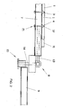
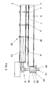
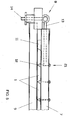
- an overall pivotable turning frame (6) can be seen, which consists of a straightening frame (7) and an adjustable Distance connected to the straightening frame (7) via at least one joint (8) Swivel frame (9) exists.
- the straightening frame (7) are in the Embodiment several spacers arranged parallel to each other (12) used. These are in the directional frame (7) transverse to it Can be moved lengthways, but can be locked in any position. This is done via a rail guide, with fixing Screw connections (21) are used.
- the spacers (12) are the center distance the connecting surfaces (3, 4) aligned accordingly, so that these into one between two individual elements from the connecting surfaces (3 and 4) Intervene in the approximately triangular free space.
- the straightening frame (7) has at least two adjustment flanges (10, 11), which is used to set a fixed distance dimension within the straightening frame (7) are required and which have a lateral border for the form adjacent individual elements (1).
- the joint (8) between straightening frame (7) and swivel frame (9) is present designed as a hinge joint, the first leg (13) immediately is connected to the straightening frame (7) and its second leg (14) in an adjusting device (15) engages, which in turn connects to the Has pivot frame (9).
- the adjusting device (15) in the present case consists of a socket (16) an internal thread (17) into which an insert (18) can be screwed.
- the stake in turn has an opposite to the internal thread (17) common thread (19) into which one leg (14) of the joint (8) can be screwed in.
- the hollow body to be produced can have any cross sections, so it is it is possible with the presented method and the associated device triangular, rectangular, square or generally polygonal hollow bodies to create.
Landscapes
- Life Sciences & Earth Sciences (AREA)
- Engineering & Computer Science (AREA)
- Wood Science & Technology (AREA)
- Forests & Forestry (AREA)
- Manufacturing & Machinery (AREA)
- Mechanical Engineering (AREA)
- Making Paper Articles (AREA)
- Securing Of Glass Panes Or The Like (AREA)
- Separation Using Semi-Permeable Membranes (AREA)
Abstract
- Vorfertigung von Einzelelementen (1), deren Querschnitt jeweils ein Segment des fertiggestellten Hohlkörpers (2) bildet, wobei an jedem Einzelelement (1) zwei Verbindungsflächen (3, 4) zur Befestigung der Einzelelemente (1) aneinander vorhanden sind,
- ausgerichtetes Aneinanderlegen der Einzelelemente (1), so dass eine annähernd plattenförmige, geschlossene, am Fertigteil die Außenseite bildende Oberfläche entsteht,
- Aufbringung mindestens eines Klebebandstreifens (5) auf diese Oberfläche,
- Wenden der Baugruppe,
- Benetzung der Verbindungsflächen (3, 4) mit Bindemitteln oder Klebstoff,
- Aufwickeln der Einzelelemente (1) bis ein geschlossener Hohlkörper (2) entstanden ist und anschließendes Verspannen des Hohlkörpers mittels wenigstens eines Klebebandstreifens.
Description
- Figur 1:
- einen Wenderahmen in aufgeklappter Stellung,
- Figur 2:
- in den Richtrahmen eingelegte Einzelelemente,
- Figur 3:
- die um 180° verschwenkte Stellung des Schwenkrahmens im geöffneten Zustand,
- Figur 4:
- den Schwenkrahmen im geschlossenen Zustand,
- Figur 5:
- den Wenderahmen in einer verglichen mit der Darstellung in Figur 4 um 180° verschwenkten Stellung,
- Figur 6:
- den erneut aufgeklappten Wenderahmen, wobei der Richtrahmen um 180° verschwenkt ist,
- Figur 7:
- Fertigstellung des ersten Hohlkörpers bei gleichzeitigem Beginn der Herstellung des nächsten Werkstückes.
- Vorfertigung von Einzelelementen (1), deren Querschnitt jeweils ein Segment des fertiggestellten Hohlkörpers (2) bildet, wobei an jedem Einzelelement (1) zwei Verbindungsflächen (3, 4) zur Befestigung der Einzelelemente (1) aneinander vorhanden sind, die zusammengelegt einen dreieckigen Hohlraum bilden,
- ausgerichtetes Aneinanderlegen der Einzelelemente (1) in den Richtrahmen, so dass eine annähernd plattenförmige, geschlossene, am Fertigteil die Außenseite bildende Oberfläche entsteht und die Verbindungsflächen (3 und 4) der Einzelelemente (1) an den im Richtrahmen (7) festgesetzten Abstandshaltern (12) anliegen, wobei die Justierflansche (10, 11) dabei die seitlichen Randbegrenzungen der Einzelelmenete (1) bilden
- Aufbringung mehrerer paralleler Klebebandstreifen (5) auf die Oberfläche,
- Schließen des Wenderahmens (6) durch Verschwenkung des Schwenkrahmens (9) um 180° um das Gelenk (8)
- bei dem ersten Verfahrensdurchchlauf einer Serie wird zunächst der Abstand zwischen Richtrahmen (7) und Schwenkrahmen (9) auf das Abstandsmaß der Materialstärke der Einzelelmenete (1) eingestellt, indem mittels eines Werkzeugs der Einsatz (18) gedreht wird, sodass die gegenläufigen Gewinde (17 und 19) einen Hub des Schwenkrahmens (9) relativ zum Richtrahmen (7) bewirken,
- Schwenken des gesamten Wenderahmens (6) um 180°, so dass die Verbindungsflächen (3, 4) nach Öffnen des nunmehr oberen Richtrahmens (7) frei liegen,
- Benetzung der Verbindungsflächen (3, 4) mit Klebstoff,
- Aufwickeln der Einzelelemente (1) bis ein geschlossener Hohlkörper (2) entstanden ist und anschließendes Verspannen des Hohlkörpers mittels eines Klebebandstreifens, während der Richtrahmen für den nächsten Durchlauf bereits wieder beschickt werden kann.
Claims (9)
- Verfahren zur Herstellung von Hohlkörpern, gekennzeichnet durch folgende Verfahrensschritte:Vorfertigung von Einzelelementen (1), deren Querschnitt jeweils ein Segment des fertiggestellten Hohlkörpers (2) bildet, wobei an jedem Einzelelement (1) zwei Verbindungsflächen (3, 4) zur Befestigung der Einzelelemente (1) aneinander vorhanden sind,ausgerichtetes Aneinanderlegen der Einzelelemente (1), so dass eine annähernd plattenförmige, geschlossene, am Fertigteil die Außenseite bildende Oberfläche entsteht,Aufbringung mindestens eines Klebebandstreifens (5) auf diese Oberfläche,Wenden der Baugruppe, Benetzung der Verbindungsflächen (3, 4) mit Bindemitteln oder Klebstoff,Aufwickeln der Einzelelemente (1) bis ein geschlossener Hohlkörper (2) entstanden ist und anschließendes Verspannen des Hohlkörpers mittels wenigstens eines Klebebandstreifens.
- Verfahren zur Herstellung von Hohlkörpern nach Anspruch 1, dadurch gekennzeichnet, dass zum Verspannen des geschlossenen Hohlkörpers (2) mindestens ein überstehendes Ende des wenigstens einen zur Herstellung der plattenförmigen Baugruppe eingesetzten Klebebandstreifens (5) verwendet wird.
- Verfahren zur Herstellung von Hohlkörpern nach Anspruch 1 oder 2, dadurch gekennzeichnet, dass nach Trocknung des Bindemittels oder Klebstoffes die Klebebandstreifen (5) entfernt werden.
- Vorrichtung zur Herstellung eines Hohlkörpers unter Einsatz eines Verfahrens nach einem der vorhergehenden Ansprüche, dadurch gekennzeichnet, dass die Vorrichtung mindestens einen insgesamt schwenkbaren Wenderahmen (6) aufweist, der seinerseits aus einem Richtrahmen (7) und einem in einstellbarem Abstand über wenigstens ein Gelenk (8) mit dem Richtrahmen (7) verbundenen Schwenkrahmen (9) besteht, wobei der Richtrahmen (7) zumindest zwei Justierflansche (10, 11) aufweist, von denen wenigstens einer zur Einstellung eines fixen Abstandsmaßes innerhalb des Richtrahmens (7) versetzbar ausgeführt ist.
- Vorrichtung nach Anspruch 4, dadurch gekennzeichnet, dass der Richtrahmen (7) dem Mittenabstand der Verbindungsflächen (3, 4) entsprechend ausrichtbare Abstandshalter (12) aufweist.
- Vorrichtung nach Anspruch 4 oder 5, dadurch gekennzeichnet, dass der Richtrahmen (7) mindestens eine Skalierung zur Einstellung der werkstückbezogenen Abmaße aufweist.
- Vorrichtung nach einem der Ansprüche 4 bis 6, dadurch gekennzeichnet, dass das Gelenk (8) zwischen Richtrahmen (7) und Schwenkrahmen (9) ein Schamiergelenk ist, dessen erster Schenkel (13) unmittelbar mit dem Richtrahmen (7) verbunden ist und dessen zweiter Schenkel (14) in eine Verstelleinrichtung (15) eingreift, die ihrerseits eine Verbindung zu dem Schwenkrahmen (9) aufweist.
- Vorrichtung nach Anspruch 7, dadurch gekennzeichnet, dass die Verstelleinrichtung (15) eine mechanisch, hydraulisch, pneumatisch oder elektromagnetisch angetriebene Hubeinrichtung aufweist.
- Vorrichtung nach Anspruch 8, dadurch gekennzeichnet, dass die Verstelleinrichtung (15) eine Buchse (16) mit einem Innengewinde (17) aufweist, in das ein Einsatz (18) einschraubbar ist und der Einsatz ein zu dem Innengewinde (17) entgegengesetzt gängiges Gewinde (19) aufweist, das mit einem Schenkel (14) des Gelenkes (8) verschraubbar ist und an dem Einsatz ferner eine Eingriffs- oder Angriffsfläche (20) für ein Werkzeug oder die Hubeinrichtung vorhanden ist.
Applications Claiming Priority (2)
| Application Number | Priority Date | Filing Date | Title |
|---|---|---|---|
| DE10130001A DE10130001C1 (de) | 2001-06-25 | 2001-06-25 | Verfahren zur Herstellung von Hohlkörpern und Vorrichtung zur Herstellung eines derartigen Hohlkörpers |
| DE10130001 | 2001-06-25 |
Publications (3)
| Publication Number | Publication Date |
|---|---|
| EP1270156A2 true EP1270156A2 (de) | 2003-01-02 |
| EP1270156A3 EP1270156A3 (de) | 2005-02-02 |
| EP1270156B1 EP1270156B1 (de) | 2007-08-01 |
Family
ID=7688995
Family Applications (1)
| Application Number | Title | Priority Date | Filing Date |
|---|---|---|---|
| EP02012529A Expired - Lifetime EP1270156B1 (de) | 2001-06-25 | 2002-06-05 | Verfahren zur Herstellung von Hohlkörpern und Vorrichtung zur Herstellung eines derartigen Hohlkörpers |
Country Status (3)
| Country | Link |
|---|---|
| EP (1) | EP1270156B1 (de) |
| AT (1) | ATE368555T1 (de) |
| DE (1) | DE10130001C1 (de) |
Cited By (1)
| Publication number | Priority date | Publication date | Assignee | Title |
|---|---|---|---|---|
| EP1990163A3 (de) * | 2007-05-08 | 2012-08-08 | ISP Systems S.r.l. | Verfahren und Maschinezur Herstellung eines kastenförmigen Teils aus Holz oder holzartigem Material |
Family Cites Families (5)
| Publication number | Priority date | Publication date | Assignee | Title |
|---|---|---|---|---|
| GB104927A (en) * | 1916-03-25 | 1917-03-26 | Ernest Parker Everett | Method for Making Barrels, Pails and other like Coopered Vessels. |
| JPS5519563A (en) * | 1978-07-28 | 1980-02-12 | Amino Tekko Kk | Wood columnar wood and its preparation |
| DE8906851U1 (de) * | 1989-06-03 | 1989-12-28 | Geling, Alfons, 7842 Kandern | Holzrohr mit Steckverbindung |
| JPH03239501A (ja) * | 1990-02-15 | 1991-10-25 | Yoshihisa Koyama | 多角形中空シャフト並びにその製造方法並びに複層シャフト部材の製造方法並びに多角形シャフト並びにシャフトの握部並びに円形シャフト並びに中空シャフト用節部材及びシャフトの継手 |
| EP1038646A1 (de) * | 1999-03-25 | 2000-09-27 | Akzo Nobel N.V. | Verfahren und Vorrichung zum Auftragen von Leim |
-
2001
- 2001-06-25 DE DE10130001A patent/DE10130001C1/de not_active Expired - Fee Related
-
2002
- 2002-06-05 EP EP02012529A patent/EP1270156B1/de not_active Expired - Lifetime
- 2002-06-05 AT AT02012529T patent/ATE368555T1/de not_active IP Right Cessation
Cited By (1)
| Publication number | Priority date | Publication date | Assignee | Title |
|---|---|---|---|---|
| EP1990163A3 (de) * | 2007-05-08 | 2012-08-08 | ISP Systems S.r.l. | Verfahren und Maschinezur Herstellung eines kastenförmigen Teils aus Holz oder holzartigem Material |
Also Published As
| Publication number | Publication date |
|---|---|
| EP1270156B1 (de) | 2007-08-01 |
| ATE368555T1 (de) | 2007-08-15 |
| EP1270156A3 (de) | 2005-02-02 |
| DE10130001C1 (de) | 2003-03-20 |
Similar Documents
| Publication | Publication Date | Title |
|---|---|---|
| DE69307038T2 (de) | Verfahren zum Vorbereiten des Randes anschliessend zu beschichtender Spanplatten und so erhaltene Spanplatten | |
| DE19804787A1 (de) | Verfahren zum Herstellen faltbarer Faserplatten | |
| DE202021106266U1 (de) | Verbinder und ALC-Montageknotenstruktur | |
| DE69913002T2 (de) | Verfahren zur herstellung einer platte sowie nach diesem verfahren hergestellte platte | |
| DE60222397T2 (de) | Innen-einspannung | |
| EP0426015B1 (de) | Mehrschichtmassivholzerzeugnisse wie Balken, Bretter und Leimbinder sowie Verfahren zu deren Herstellung | |
| AT506402B1 (de) | Halteelement zum anbringen von schalungselementen | |
| EP1270156B1 (de) | Verfahren zur Herstellung von Hohlkörpern und Vorrichtung zur Herstellung eines derartigen Hohlkörpers | |
| EP3402367B1 (de) | Möbelplatte | |
| DE102009050861A1 (de) | Vorrichtung zum Abbinden eines Rundholzes | |
| EP3612687A1 (de) | Fachwerkträger für den baubereich und verfahren zur herstellung solcher fachwerkträger | |
| EP1792723A1 (de) | Verfahren und Vorrichtung zur Herstellung einer Leichtbauplatte und Leichtbauplatte | |
| EP2775231B1 (de) | Montagebügel | |
| DE3440272C2 (de) | ||
| EP0074623A2 (de) | Verfahren zum Herstellen von Türblättern | |
| DE19505141A1 (de) | Verfahren zur Verbindung zweier parallel aufeinanderliegender Flachtafeln und Vorrichtung zur Durchführung des Verfahrens | |
| EP1364599B9 (de) | Faltbare Platte mit Nut & Feder | |
| DE602004003192T2 (de) | Bauteil eines Musikinstruments, wie Seitenplatte eines Klaviergehäuses, sowie Herstellungsverfahren | |
| DE2754519A1 (de) | Befestigungsmittel, insbesondere krallenplatte, zur verbindung von holzbauteilen | |
| WO2020007633A1 (de) | Armaturenverstärkung für eine spüle und verfahren zum abstützen einer armatur bei einer spüle | |
| DE19627664A1 (de) | Zentrier- und Befestigungsvorrichtung sowie mechanisches Verbindungselement zur Verwendung darin | |
| DE202007007888U1 (de) | Element und System zum Aufbau von Vorrichtungen zum Aufspannen von Werkstücken | |
| DE3621062C2 (de) | ||
| WO2017134696A1 (de) | Schafträser | |
| DE102013200861A1 (de) | Verfahren zur Montage eines Fertigdecks |
Legal Events
| Date | Code | Title | Description |
|---|---|---|---|
| PUAI | Public reference made under article 153(3) epc to a published international application that has entered the european phase |
Free format text: ORIGINAL CODE: 0009012 |
|
| AK | Designated contracting states |
Kind code of ref document: A2 Designated state(s): AT BE CH CY DE DK ES FI FR GB GR IE IT LI LU MC NL PT SE TR |
|
| AX | Request for extension of the european patent |
Free format text: AL;LT;LV;MK;RO;SI |
|
| PUAL | Search report despatched |
Free format text: ORIGINAL CODE: 0009013 |
|
| AK | Designated contracting states |
Kind code of ref document: A3 Designated state(s): AT BE CH CY DE DK ES FI FR GB GR IE IT LI LU MC NL PT SE TR |
|
| AX | Request for extension of the european patent |
Extension state: AL LT LV MK RO SI |
|
| 17P | Request for examination filed |
Effective date: 20050705 |
|
| AKX | Designation fees paid |
Designated state(s): AT BE CH CY DE DK ES FI FR GB GR IE IT LI LU MC NL PT SE TR |
|
| GRAC | Information related to communication of intention to grant a patent modified |
Free format text: ORIGINAL CODE: EPIDOSCIGR1 |
|
| GRAP | Despatch of communication of intention to grant a patent |
Free format text: ORIGINAL CODE: EPIDOSNIGR1 |
|
| GRAS | Grant fee paid |
Free format text: ORIGINAL CODE: EPIDOSNIGR3 |
|
| RBV | Designated contracting states (corrected) |
Designated state(s): AT BE CH CY DK ES FI FR GB GR IE IT LI LU MC NL PT SE TR |
|
| GRAA | (expected) grant |
Free format text: ORIGINAL CODE: 0009210 |
|
| AK | Designated contracting states |
Kind code of ref document: B1 Designated state(s): AT BE CH CY DK ES FI FR GB GR IE IT LI LU MC NL PT SE TR |
|
| REG | Reference to a national code |
Ref country code: GB Ref legal event code: FG4D Free format text: NOT ENGLISH |
|
| REG | Reference to a national code |
Ref country code: DE Ref legal event code: 8566 |
|
| REG | Reference to a national code |
Ref country code: CH Ref legal event code: EP Ref country code: CH Ref legal event code: NV Representative=s name: KATZAROV S.A. |
|
| REG | Reference to a national code |
Ref country code: IE Ref legal event code: FG4D Free format text: LANGUAGE OF EP DOCUMENT: GERMAN |
|
| PG25 | Lapsed in a contracting state [announced via postgrant information from national office to epo] |
Ref country code: ES Free format text: LAPSE BECAUSE OF FAILURE TO SUBMIT A TRANSLATION OF THE DESCRIPTION OR TO PAY THE FEE WITHIN THE PRESCRIBED TIME-LIMIT Effective date: 20071112 Ref country code: FI Free format text: LAPSE BECAUSE OF FAILURE TO SUBMIT A TRANSLATION OF THE DESCRIPTION OR TO PAY THE FEE WITHIN THE PRESCRIBED TIME-LIMIT Effective date: 20070801 |
|
| GBV | Gb: ep patent (uk) treated as always having been void in accordance with gb section 77(7)/1977 [no translation filed] |
Effective date: 20070801 |
|
| REG | Reference to a national code |
Ref country code: IE Ref legal event code: FD4D |
|
| EN | Fr: translation not filed | ||
| PG25 | Lapsed in a contracting state [announced via postgrant information from national office to epo] |
Ref country code: DK Free format text: LAPSE BECAUSE OF FAILURE TO SUBMIT A TRANSLATION OF THE DESCRIPTION OR TO PAY THE FEE WITHIN THE PRESCRIBED TIME-LIMIT Effective date: 20070801 Ref country code: GR Free format text: LAPSE BECAUSE OF FAILURE TO SUBMIT A TRANSLATION OF THE DESCRIPTION OR TO PAY THE FEE WITHIN THE PRESCRIBED TIME-LIMIT Effective date: 20071102 |
|
| PG25 | Lapsed in a contracting state [announced via postgrant information from national office to epo] |
Ref country code: PT Free format text: LAPSE BECAUSE OF FAILURE TO SUBMIT A TRANSLATION OF THE DESCRIPTION OR TO PAY THE FEE WITHIN THE PRESCRIBED TIME-LIMIT Effective date: 20080102 Ref country code: IE Free format text: LAPSE BECAUSE OF FAILURE TO SUBMIT A TRANSLATION OF THE DESCRIPTION OR TO PAY THE FEE WITHIN THE PRESCRIBED TIME-LIMIT Effective date: 20070801 Ref country code: GB Free format text: LAPSE BECAUSE OF FAILURE TO SUBMIT A TRANSLATION OF THE DESCRIPTION OR TO PAY THE FEE WITHIN THE PRESCRIBED TIME-LIMIT Effective date: 20070801 |
|
| PLBE | No opposition filed within time limit |
Free format text: ORIGINAL CODE: 0009261 |
|
| STAA | Information on the status of an ep patent application or granted ep patent |
Free format text: STATUS: NO OPPOSITION FILED WITHIN TIME LIMIT |
|
| PG25 | Lapsed in a contracting state [announced via postgrant information from national office to epo] |
Ref country code: SE Free format text: LAPSE BECAUSE OF FAILURE TO SUBMIT A TRANSLATION OF THE DESCRIPTION OR TO PAY THE FEE WITHIN THE PRESCRIBED TIME-LIMIT Effective date: 20071101 |
|
| 26N | No opposition filed |
Effective date: 20080506 |
|
| PG25 | Lapsed in a contracting state [announced via postgrant information from national office to epo] |
Ref country code: FR Free format text: LAPSE BECAUSE OF FAILURE TO SUBMIT A TRANSLATION OF THE DESCRIPTION OR TO PAY THE FEE WITHIN THE PRESCRIBED TIME-LIMIT Effective date: 20080328 |
|
| BERE | Be: lapsed |
Owner name: LEMBECK, STEFAN Effective date: 20080630 |
|
| PG25 | Lapsed in a contracting state [announced via postgrant information from national office to epo] |
Ref country code: MC Free format text: LAPSE BECAUSE OF NON-PAYMENT OF DUE FEES Effective date: 20080630 |
|
| PG25 | Lapsed in a contracting state [announced via postgrant information from national office to epo] |
Ref country code: BE Free format text: LAPSE BECAUSE OF NON-PAYMENT OF DUE FEES Effective date: 20080630 |
|
| PG25 | Lapsed in a contracting state [announced via postgrant information from national office to epo] |
Ref country code: CY Free format text: LAPSE BECAUSE OF FAILURE TO SUBMIT A TRANSLATION OF THE DESCRIPTION OR TO PAY THE FEE WITHIN THE PRESCRIBED TIME-LIMIT Effective date: 20070801 |
|
| PGFP | Annual fee paid to national office [announced via postgrant information from national office to epo] |
Ref country code: NL Payment date: 20090624 Year of fee payment: 8 |
|
| PGFP | Annual fee paid to national office [announced via postgrant information from national office to epo] |
Ref country code: AT Payment date: 20090622 Year of fee payment: 8 |
|
| PGFP | Annual fee paid to national office [announced via postgrant information from national office to epo] |
Ref country code: CH Payment date: 20090624 Year of fee payment: 8 |
|
| PG25 | Lapsed in a contracting state [announced via postgrant information from national office to epo] |
Ref country code: LU Free format text: LAPSE BECAUSE OF NON-PAYMENT OF DUE FEES Effective date: 20080605 |
|
| PG25 | Lapsed in a contracting state [announced via postgrant information from national office to epo] |
Ref country code: TR Free format text: LAPSE BECAUSE OF FAILURE TO SUBMIT A TRANSLATION OF THE DESCRIPTION OR TO PAY THE FEE WITHIN THE PRESCRIBED TIME-LIMIT Effective date: 20070801 |
|
| REG | Reference to a national code |
Ref country code: NL Ref legal event code: V1 Effective date: 20110101 |
|
| REG | Reference to a national code |
Ref country code: CH Ref legal event code: PL |
|
| PG25 | Lapsed in a contracting state [announced via postgrant information from national office to epo] |
Ref country code: IT Free format text: LAPSE BECAUSE OF NON-PAYMENT OF DUE FEES Effective date: 20080630 |
|
| PG25 | Lapsed in a contracting state [announced via postgrant information from national office to epo] |
Ref country code: LI Free format text: LAPSE BECAUSE OF NON-PAYMENT OF DUE FEES Effective date: 20100630 Ref country code: CH Free format text: LAPSE BECAUSE OF NON-PAYMENT OF DUE FEES Effective date: 20100630 |
|
| PG25 | Lapsed in a contracting state [announced via postgrant information from national office to epo] |
Ref country code: AT Free format text: LAPSE BECAUSE OF NON-PAYMENT OF DUE FEES Effective date: 20100605 Ref country code: NL Free format text: LAPSE BECAUSE OF NON-PAYMENT OF DUE FEES Effective date: 20110101 |