EP1269923B1 - Lame pour scie chirurgicale - Google Patents
Lame pour scie chirurgicale Download PDFInfo
- Publication number
- EP1269923B1 EP1269923B1 EP02011940A EP02011940A EP1269923B1 EP 1269923 B1 EP1269923 B1 EP 1269923B1 EP 02011940 A EP02011940 A EP 02011940A EP 02011940 A EP02011940 A EP 02011940A EP 1269923 B1 EP1269923 B1 EP 1269923B1
- Authority
- EP
- European Patent Office
- Prior art keywords
- teeth
- saw blade
- tooth
- blade according
- pair
- Prior art date
- Legal status (The legal status is an assumption and is not a legal conclusion. Google has not performed a legal analysis and makes no representation as to the accuracy of the status listed.)
- Expired - Lifetime
Links
- 238000005520 cutting process Methods 0.000 abstract description 17
- 210000000988 bone and bone Anatomy 0.000 description 4
- 230000002349 favourable effect Effects 0.000 description 3
- 206010038743 Restlessness Diseases 0.000 description 2
- 230000015572 biosynthetic process Effects 0.000 description 1
- 238000010276 construction Methods 0.000 description 1
- 238000004519 manufacturing process Methods 0.000 description 1
- 238000013508 migration Methods 0.000 description 1
- 230000005012 migration Effects 0.000 description 1
- 230000002265 prevention Effects 0.000 description 1
Images


Classifications
-
- B—PERFORMING OPERATIONS; TRANSPORTING
- B23—MACHINE TOOLS; METAL-WORKING NOT OTHERWISE PROVIDED FOR
- B23D—PLANING; SLOTTING; SHEARING; BROACHING; SAWING; FILING; SCRAPING; LIKE OPERATIONS FOR WORKING METAL BY REMOVING MATERIAL, NOT OTHERWISE PROVIDED FOR
- B23D61/00—Tools for sawing machines or sawing devices; Clamping devices for these tools
- B23D61/006—Oscillating saw blades
-
- A—HUMAN NECESSITIES
- A61—MEDICAL OR VETERINARY SCIENCE; HYGIENE
- A61B—DIAGNOSIS; SURGERY; IDENTIFICATION
- A61B17/00—Surgical instruments, devices or methods, e.g. tourniquets
- A61B17/14—Surgical saws ; Accessories therefor
- A61B17/142—Surgical saws ; Accessories therefor with reciprocating saw blades, e.g. with cutting edges at the distal end of the saw blades
-
- B—PERFORMING OPERATIONS; TRANSPORTING
- B23—MACHINE TOOLS; METAL-WORKING NOT OTHERWISE PROVIDED FOR
- B23D—PLANING; SLOTTING; SHEARING; BROACHING; SAWING; FILING; SCRAPING; LIKE OPERATIONS FOR WORKING METAL BY REMOVING MATERIAL, NOT OTHERWISE PROVIDED FOR
- B23D61/00—Tools for sawing machines or sawing devices; Clamping devices for these tools
- B23D61/02—Circular saw blades
- B23D61/021—Types of set; Variable teeth, e.g. variable in height or gullet depth; Varying pitch; Details of gullet
Definitions
- the invention relates to a surgical saw blade with a clamping area and provided with a toothing work area.
- Surgical saw blades of the type described are known from the prior art in a variety of embodiments. They are mounted on a drive unit, by which they are displaceable in an oscillating, reciprocating motion. This makes it possible, for example, perform precise bone sections.
- the saw blades can either be manually guided, but it is also possible to use them in conjunction with templates to precisely create predetermined cuts.
- a surgical saw blade which has unrestricted teeth.
- the teeth are each ground alternately from different sides or provided with a chamfer and also have on each side a fillet grinding.
- the Fillet cuts are formed alternately on one or the other surface of the body of the saw blade.
- saw blades are slightly better according to the above-mentioned US Patent, but they behave in the practical application, however, still very restless.
- a circular saw blade is previously known, which can be used for non-medical purposes and can be used in both directions of rotation.
- carbide cutting inserts are arranged in pairs, which protrude laterally beyond the plane of the circular saw blade.
- the invention has for its object to provide a surgical blade of the type mentioned, which shows a simple structure and cost manufacturability optimized cutting behavior and allows a significant cut without significant damage from surrounding bone material.
- the saw blade according to the invention is characterized by a number of significant advantages.
- the toothing respectively Includes pairs of two immediately adjacent teeth, which, based on a plane perpendicular to the median plane of the body, are symmetrical to each other.
- this symmetrical design of the teeth is also a uniform force entry into the teeth, so that it centers very well and leads to a very smooth cutting process. It is thus possible to guide the saw blade more targeted and to produce more precise bone sections.
- each tooth is configured in the form of an isosceles or skew-angled triangle-forming body in side view, on whose one edge a bevel is ground on one side.
- the cutting edges are used alternately to different sides of the body of the saw blade. This leads to a quiet cut and a prevention of chatter marks or the like.
- the chamfers of each pair of teeth can preferably be designed pointing away from one another.
- the saw blade can be used in the same way in both cutting directions.
- the inventively provided pairs of teeth are each arranged alternately to the median plane of the body of the saw blade. This means that once “left” pairs of Teeth are used, followed by pairs of "right” teeth. This also increases the precision of the cutting guide and the quiet handling of the saw blade.
- At least one further tooth is arranged between two adjacent pairs of teeth. This can be done via additional, modified cutting geometries, on the one hand to improve the centering and on the other to remove bony areas that are not workable by the two successive pairs of teeth in an optimal manner.
- the at least one further tooth may have the same height as the adjacent pairs of teeth, but it is also possible to provide a different height. It may be advantageous, for example, to make the other tooth higher or lower. Furthermore, it is possible to provide the further tooth with a transverse cutting edge, so that a different cutting geometry results for this tooth.
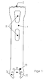
- a saw blade is shown in the side view, which has a substantially flat, plate-shaped body 1, which is provided at its edge region with an arcuate toothing 2.
- a substantially circular clamping area 14 which is provided with mounting recesses 12, 13.
- the dimensioning and design of the body 1 and the mounting recesses 12 and 13 and the clamping area 14 correspond to the prior art and can be adapted to the respective conditions of use. A detailed description can be omitted here.
- the toothing 2 is preferably designed arcuate, so that in a vibrating, reciprocating oscillating movement about the central axis of the mounting recess 12 a uniform cut can be made.
- FIGs. 2 and 3 show an embodiment of the toothing according to the invention.
- This comprises pairs 5, 6, each with two teeth 3, 4.
- FIG. 2 shows an enlarged detail view of such a pair of teeth 3, 4.
- the teeth are formed symmetrically to a symmetry axis arranged perpendicular to the median plane of the body 1, they respectively on the opposite side a chamfer 7, through which the corresponding cutting edges are formed.
- the two teeth of each pair 5, 6 are each the same height, they are essentially from a tooth blank, not shown, which forms the shape of an isosceles or skewed triangle generated.
- pairs 5, 6 of teeth 3, 4 are alternately provided.
- the pairs of teeth are the same, however, their orientation is based on the center plane, not shown, of the body 1, chosen alternately, so that the chamfers of the one pair 5 point to one side of the body 1, while the chamfers of the other pair 6 to directed to the other side of the body 1.
- 4 and 5 show a modified embodiment in which between the individual pairs 5, 6 each further teeth 8, 9 are arranged. 4 shows an enlarged detail illustration for this purpose.
- identical teeth are used in each case, also for the further teeth 8, 9.
- the arrangement and alignment of the further teeth 8, 9 takes place in such a way that the further tooth 8 adjoining each pair 5 is equal to the first tooth 3 of the subsequent pair 6.
- the subsequent to the tooth 3 of the pair 6 further tooth 9 is the same formed to the first tooth 4 of the subsequent pair of teeth 5.
- the further teeth 8, 9 may have the same height as the teeth 3, 4 of the respective pair 5 and 6. However, it is also possible to provide the further teeth 8, 9 with a greater height or a smaller height.
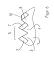
- FIG. 6 From Figs. 6 and 7, another embodiment can be seen, in which between the adjacent pairs 5 and 6 only one further tooth 8 is arranged. This is designed in different geometry. In the embodiment shown, it is, as is also apparent from the enlarged view of FIG. 6, formed lower and provided with a transverse cutting edge 10.
- the toothing invention leads, as already mentioned, to a precise saw cut, which is very efficient.
- the cutting width corresponds at least to the saw blade thickness.
- Fig. 8 shows an embodiment, similar to the representation of Fig. 7, in which all teeth are provided with lateral grooves. It is understood that individual groups can be formed with such lateral grooves. Furthermore, it is understood that the flutes do not have to be provided on both sides of the teeth, but it is possible to provide the individual groups only on one side with a groove, to arrange the flutes alternately or to choose an alternate configuration.
Landscapes
- Health & Medical Sciences (AREA)
- Engineering & Computer Science (AREA)
- Mechanical Engineering (AREA)
- Life Sciences & Earth Sciences (AREA)
- Surgery (AREA)
- Animal Behavior & Ethology (AREA)
- Oral & Maxillofacial Surgery (AREA)
- Biomedical Technology (AREA)
- Heart & Thoracic Surgery (AREA)
- Medical Informatics (AREA)
- Molecular Biology (AREA)
- Nuclear Medicine, Radiotherapy & Molecular Imaging (AREA)
- General Health & Medical Sciences (AREA)
- Public Health (AREA)
- Veterinary Medicine (AREA)
- Dentistry (AREA)
- Surgical Instruments (AREA)
- Saccharide Compounds (AREA)
- Dental Tools And Instruments Or Auxiliary Dental Instruments (AREA)
- Knives (AREA)
Claims (11)
- Lame de scie chirurgicale pour scie oscillante, comportant un corps (1) plat en forme de plaque, qui est muni au moins sur un bord d'une denture (2) présentant une pluralité de dents non avoyées, la denture (2) comportant respectivement des paires (5, 6) de deux dents (3, 4) directement adjacentes, caractérisée en ce que les deux dents (3, 4) directement adjacentes, par rapport à un plan perpendiculaire au plan médian du corps (1), sont réalisées symétriquement l'une à l'autre, et en ce que les paires (5, 6) de dents (3, 4) sont disposées respectivement en alternance par rapport au plan médian du corps (1).
- Lame de scie selon la revendication 1, caractérisée en ce que chaque dent (3, 4) est réalisée sous la forme d'un corps, qui forme sur la vue de profil un triangle isocèle ou scalène et dont une arête est réalisée sur un côté avec un chanfrein (7).
- Lame de scie selon la revendication 2, caractérisée en ce que les chanfreins (7) de chaque paire (5, 6) de dents (3, 4) sont réalisés en s'écartant l'un de l'autre.
- Lame de scie selon l'une quelconque des revendications 1 à 3, caractérisée en ce qu'au moins une dent (8, 9) supplémentaire est située entre deux paires (5, 6) adjacentes de dents (3, 4).
- Lame de scie selon la revendication 4, caractérisée en ce que ladite au moins une dent (8, 9) supplémentaire présente la même hauteur que les dents (3, 4) de la paire (5, 6).
- Lame de scie selon la revendication 4, caractérisée en ce que ladite au moins une dent (8, 9) supplémentaire présente une hauteur différente de celle des dents (3, 4) de la paire (5, 6).
- Lame de scie selon la revendication 6, caractérisée en ce que ladite au moins une dent (8, 9) supplémentaire est plus haute.
- Lame de scie selon la revendication 6, caractérisée en ce que ladite au moins une dent (8, 9) supplémentaire est plus basse.
- Lame de scie selon l'une quelconque des revendications 4 à 8, caractérisée en ce que ladite au moins une dent (8) supplémentaire est munie d'un tranchant transversal.
- Lame de scie selon l'une quelconque des revendications 4 à 9, caractérisée en ce que deux dents supplémentaires (8, 9) sont situées entre les deux paires (5, 6) adjacentes de dents (3, 4), la dent (8, 9) dans le prolongement d'une paire (5, 6) de dents est réalisée à l'identique de la dent (3, 4) directement suivante de la paire (5, 6) suivante.
- Lame de scie selon l'une quelconque des revendications 4 à 10, caractérisée en ce que certains tranchants ou tous les tranchants sont modifiés sur le côté par des gorges creuses.
Applications Claiming Priority (4)
| Application Number | Priority Date | Filing Date | Title |
|---|---|---|---|
| DE10130007 | 2001-06-25 | ||
| DE10130007A DE10130007C1 (de) | 2001-06-25 | 2001-06-25 | Chirurgisches Sägeblatt |
| DE10131023 | 2001-06-25 | ||
| DE10131023A DE10131023C1 (de) | 2001-06-25 | 2001-06-25 | Chirurgisches Sägeblatt |
Publications (3)
| Publication Number | Publication Date |
|---|---|
| EP1269923A2 EP1269923A2 (fr) | 2003-01-02 |
| EP1269923A3 EP1269923A3 (fr) | 2004-02-04 |
| EP1269923B1 true EP1269923B1 (fr) | 2006-10-11 |
Family
ID=26009563
Family Applications (1)
| Application Number | Title | Priority Date | Filing Date |
|---|---|---|---|
| EP02011940A Expired - Lifetime EP1269923B1 (fr) | 2001-06-25 | 2002-05-29 | Lame pour scie chirurgicale |
Country Status (5)
| Country | Link |
|---|---|
| US (1) | US20030014067A1 (fr) |
| EP (1) | EP1269923B1 (fr) |
| AT (1) | ATE342002T1 (fr) |
| DE (1) | DE50208380D1 (fr) |
| ES (1) | ES2273945T3 (fr) |
Families Citing this family (27)
| Publication number | Priority date | Publication date | Assignee | Title |
|---|---|---|---|---|
| US7691106B2 (en) * | 2005-09-23 | 2010-04-06 | Synvasive Technology, Inc. | Transverse acting surgical saw blade |
| US8672943B2 (en) * | 2009-05-12 | 2014-03-18 | Synvasive Technology, Inc. | Surgical saw blade device and system |
| WO2011049566A1 (fr) * | 2009-10-21 | 2011-04-28 | Synvasive Technology, Inc. | Dispositif de scie chirurgicale et procédé de fabrication associé |
| US9095352B2 (en) | 2009-11-02 | 2015-08-04 | Synvasive Technology, Inc. | Bone positioning device and method |
| US8828013B2 (en) * | 2009-11-02 | 2014-09-09 | Synvasive Technology, Inc. | Bone positioning device and method |
| US9073195B2 (en) | 2010-04-29 | 2015-07-07 | Black & Decker Inc. | Universal accessory for oscillating power tool |
| US8925931B2 (en) | 2010-04-29 | 2015-01-06 | Black & Decker Inc. | Oscillating tool |
| US9186770B2 (en) | 2010-04-29 | 2015-11-17 | Black & Decker Inc. | Oscillating tool attachment feature |
| CH703107A1 (de) * | 2010-05-06 | 2011-11-15 | Marco Steiger | Sägeblatt. |
| US9149923B2 (en) | 2010-11-09 | 2015-10-06 | Black & Decker Inc. | Oscillating tools and accessories |
| US8486076B2 (en) * | 2011-01-28 | 2013-07-16 | DePuy Synthes Products, LLC | Oscillating rasp for use in an orthopaedic surgical procedure |
| USD716944S1 (en) | 2011-08-03 | 2014-11-04 | Synvasive Technology, Inc. | Surgical saw blade hub |
| US9808356B2 (en) | 2011-10-24 | 2017-11-07 | Synvasive Technology, Inc. | Knee balancing devices, systems and methods |
| US8858559B2 (en) | 2012-02-06 | 2014-10-14 | Medtronic Ps Medical, Inc. | Saw blade stability and collet system mechanism |
| US8936597B2 (en) | 2012-02-06 | 2015-01-20 | Medtronic Ps Medical, Inc. | Deflectable finger connection feature on surgical saw blade |
| USD682652S1 (en) | 2012-05-14 | 2013-05-21 | Campbell Hausfeld/Scott Fetzer Company | Tool accessory hub |
| USD832666S1 (en) | 2012-07-16 | 2018-11-06 | Black & Decker Inc. | Oscillating saw blade |
| USD742002S1 (en) * | 2013-09-04 | 2015-10-27 | Mako Surgical Corp. | Surgical saw blade |
| CA2861910C (fr) * | 2013-09-27 | 2017-12-05 | Kabushiki Kaisha Okada Kinzoku Kogyosho | Lame de scie |
| JP6420953B2 (ja) * | 2014-01-22 | 2018-11-07 | 株式会社岡田金属工業所 | 鋸刃 |
| US10307917B2 (en) * | 2014-09-22 | 2019-06-04 | Worktools, Inc. | Cutting blade for oscillating tool |
| US10265778B2 (en) | 2017-01-16 | 2019-04-23 | Black & Decker Inc. | Accessories for oscillating power tools |
| USD814900S1 (en) | 2017-01-16 | 2018-04-10 | Black & Decker Inc. | Blade for oscillating power tools |
| CA3151238A1 (fr) | 2018-03-06 | 2019-09-12 | Conmed Corporation | Lame de scie chirurgicale gainee a roulements |
| US11813683B2 (en) | 2018-12-05 | 2023-11-14 | Black & Decker Inc. | Saw blade with set cutting teeth |
| WO2021067382A1 (fr) | 2019-10-01 | 2021-04-08 | Milwaukee Electric Tool Corporation | Lame destinée à un outil électrique |
| USD962027S1 (en) | 2020-04-23 | 2022-08-30 | Milwaukee Electric Tool Corporation | Blade |
Family Cites Families (13)
| Publication number | Priority date | Publication date | Assignee | Title |
|---|---|---|---|---|
| US227815A (en) * | 1880-05-18 | Eli moeeis | ||
| US293130A (en) * | 1884-02-05 | Wills | ||
| US657336A (en) * | 1900-03-26 | 1900-09-04 | Raymond Dale | Saw. |
| US706447A (en) * | 1901-09-09 | 1902-08-05 | Frank Foxon | Double-acting saw. |
| US3905374A (en) * | 1974-01-28 | 1975-09-16 | American Sterilizer Co | Knee osteotomy blade |
| CH654196A5 (de) * | 1981-10-13 | 1986-02-14 | Richard Arnegger | Saegeblatt einer oszillationssaege. |
| JPS58137520A (ja) * | 1982-01-13 | 1983-08-16 | Amada Co Ltd | 鋸刃 |
| US5361665A (en) * | 1990-09-06 | 1994-11-08 | Sandvik Ab | Saw blade |
| US6022353A (en) * | 1991-05-30 | 2000-02-08 | Synasive Technology, Inc. | Surgical saw blade |
| DE9219128U1 (de) * | 1992-01-10 | 1998-04-16 | Kullmann Wikus Saegenfab | Sägeblatt |
| US5403318A (en) * | 1993-01-15 | 1995-04-04 | Boehringer Laboratories, Inc. | Apparatus and method for shaping bone |
| US5306285A (en) | 1993-04-30 | 1994-04-26 | Komet Medical | Surgical saw blade |
| DE4427204A1 (de) * | 1994-08-01 | 1996-02-08 | Stehle Werkzeug & Maschf | Kreissägeblatt |
-
2002
- 2002-05-29 DE DE50208380T patent/DE50208380D1/de not_active Expired - Lifetime
- 2002-05-29 ES ES02011940T patent/ES2273945T3/es not_active Expired - Lifetime
- 2002-05-29 EP EP02011940A patent/EP1269923B1/fr not_active Expired - Lifetime
- 2002-05-29 AT AT02011940T patent/ATE342002T1/de not_active IP Right Cessation
- 2002-06-25 US US10/179,378 patent/US20030014067A1/en not_active Abandoned
Also Published As
| Publication number | Publication date |
|---|---|
| EP1269923A2 (fr) | 2003-01-02 |
| ATE342002T1 (de) | 2006-11-15 |
| US20030014067A1 (en) | 2003-01-16 |
| EP1269923A3 (fr) | 2004-02-04 |
| DE50208380D1 (de) | 2006-11-23 |
| ES2273945T3 (es) | 2007-05-16 |
Similar Documents
| Publication | Publication Date | Title |
|---|---|---|
| EP1269923B1 (fr) | Lame pour scie chirurgicale | |
| EP1243370B1 (fr) | Méthode de production d'une lame de scie chirurgicale | |
| DE3611063C2 (fr) | ||
| DE3940552B4 (de) | Sägeblatt | |
| DE69721061T2 (de) | Zahnstruktur eines bandsägeblattes | |
| DE19681464C2 (de) | Verbesserte Lochschneidwerkzeuge | |
| EP1240872B1 (fr) | Scie chirurgicale avec partie coupante perforée | |
| EP1849429B1 (fr) | Fraise dentaire | |
| EP2277652B1 (fr) | Lame de scie ayant des dents dotées d'un élément de déformation de copeaux | |
| DE10037809A1 (de) | Sägeblatt für Handwerkzeugmaschinen | |
| EP2570216B1 (fr) | Lame de scie avec dents de surface et dents de puissance | |
| EP0085176B2 (fr) | Tête porte-lame pour machine à tailler les roues dentées | |
| EP2520389A1 (fr) | Lame de scie destinée à scier des profils creux et moulés | |
| DE4300622C2 (de) | Sägeblatt mit einem Grundkörper und ungeschränkten Zähnen | |
| EP1205274A1 (fr) | Lame de scie à ruban et procédé pour sa fabrication | |
| EP3356073A1 (fr) | Lame de scie à dent diviseuse de copeaux | |
| DE102010010589A1 (de) | Dental- oder chirurgisches Werkzeug | |
| DE19648407A1 (de) | Lochschneidevorrichtung | |
| EP1021995A2 (fr) | Outil dentaire | |
| DE3016660C2 (de) | Sägeblatt | |
| WO2014195174A1 (fr) | Outil d'usinage d'une pièce | |
| EP1644151B1 (fr) | Dispositif pour l'usinage et/ou la formation d'un évidement dans une pièce | |
| DE20221854U1 (de) | Sägeblatt | |
| DE102017203031A1 (de) | Hubsägeblatt für eine Werkzeugmaschine | |
| DE102020000882A1 (de) | Verfahren zum Herstellen eines Werkstücks, insbesondere einer Turbinenschaufel, mit einem Fräswerkzeug |
Legal Events
| Date | Code | Title | Description |
|---|---|---|---|
| PUAI | Public reference made under article 153(3) epc to a published international application that has entered the european phase |
Free format text: ORIGINAL CODE: 0009012 |
|
| 17P | Request for examination filed |
Effective date: 20020529 |
|
| AK | Designated contracting states |
Kind code of ref document: A2 Designated state(s): AT BE CH CY DE DK ES FI FR GB GR IE IT LI LU MC NL PT SE TR |
|
| AX | Request for extension of the european patent |
Free format text: AL;LT;LV;MK;RO;SI |
|
| PUAL | Search report despatched |
Free format text: ORIGINAL CODE: 0009013 |
|
| AK | Designated contracting states |
Kind code of ref document: A3 Designated state(s): AT BE CH CY DE DK ES FI FR GB GR IE IT LI LU MC NL PT SE TR |
|
| AX | Request for extension of the european patent |
Extension state: AL LT LV MK RO SI |
|
| RIC1 | Information provided on ipc code assigned before grant |
Ipc: 7B 23D 61/12 B Ipc: 7A 61B 17/14 A |
|
| AKX | Designation fees paid |
Designated state(s): AT BE CH CY DE DK ES FI FR GB GR IE IT LI LU MC NL PT SE TR |
|
| GRAP | Despatch of communication of intention to grant a patent |
Free format text: ORIGINAL CODE: EPIDOSNIGR1 |
|
| GRAS | Grant fee paid |
Free format text: ORIGINAL CODE: EPIDOSNIGR3 |
|
| GRAA | (expected) grant |
Free format text: ORIGINAL CODE: 0009210 |
|
| AK | Designated contracting states |
Kind code of ref document: B1 Designated state(s): AT BE CH CY DE DK ES FI FR GB GR IE IT LI LU MC NL PT SE TR |
|
| PG25 | Lapsed in a contracting state [announced via postgrant information from national office to epo] |
Ref country code: IE Free format text: LAPSE BECAUSE OF FAILURE TO SUBMIT A TRANSLATION OF THE DESCRIPTION OR TO PAY THE FEE WITHIN THE PRESCRIBED TIME-LIMIT Effective date: 20061011 Ref country code: FI Free format text: LAPSE BECAUSE OF FAILURE TO SUBMIT A TRANSLATION OF THE DESCRIPTION OR TO PAY THE FEE WITHIN THE PRESCRIBED TIME-LIMIT Effective date: 20061011 |
|
| REG | Reference to a national code |
Ref country code: GB Ref legal event code: FG4D Free format text: NOT ENGLISH |
|
| REG | Reference to a national code |
Ref country code: CH Ref legal event code: EP |
|
| REG | Reference to a national code |
Ref country code: IE Ref legal event code: FG4D Free format text: LANGUAGE OF EP DOCUMENT: GERMAN |
|
| REF | Corresponds to: |
Ref document number: 50208380 Country of ref document: DE Date of ref document: 20061123 Kind code of ref document: P |
|
| PG25 | Lapsed in a contracting state [announced via postgrant information from national office to epo] |
Ref country code: DK Free format text: LAPSE BECAUSE OF FAILURE TO SUBMIT A TRANSLATION OF THE DESCRIPTION OR TO PAY THE FEE WITHIN THE PRESCRIBED TIME-LIMIT Effective date: 20070111 Ref country code: SE Free format text: LAPSE BECAUSE OF FAILURE TO SUBMIT A TRANSLATION OF THE DESCRIPTION OR TO PAY THE FEE WITHIN THE PRESCRIBED TIME-LIMIT Effective date: 20070111 |
|
| REG | Reference to a national code |
Ref country code: CH Ref legal event code: NV Representative=s name: KELLER & PARTNER PATENTANWAELTE AG WINTERTHUR |
|
| GBT | Gb: translation of ep patent filed (gb section 77(6)(a)/1977) |
Effective date: 20070201 |
|
| PG25 | Lapsed in a contracting state [announced via postgrant information from national office to epo] |
Ref country code: PT Free format text: LAPSE BECAUSE OF FAILURE TO SUBMIT A TRANSLATION OF THE DESCRIPTION OR TO PAY THE FEE WITHIN THE PRESCRIBED TIME-LIMIT Effective date: 20070319 |
|
| PGFP | Annual fee paid to national office [announced via postgrant information from national office to epo] |
Ref country code: NL Payment date: 20070516 Year of fee payment: 6 |
|
| REG | Reference to a national code |
Ref country code: IE Ref legal event code: FD4D Ref country code: ES Ref legal event code: FG2A Ref document number: 2273945 Country of ref document: ES Kind code of ref document: T3 |
|
| ET | Fr: translation filed | ||
| PLBE | No opposition filed within time limit |
Free format text: ORIGINAL CODE: 0009261 |
|
| STAA | Information on the status of an ep patent application or granted ep patent |
Free format text: STATUS: NO OPPOSITION FILED WITHIN TIME LIMIT |
|
| 26N | No opposition filed |
Effective date: 20070712 |
|
| BERE | Be: lapsed |
Owner name: GEBR. BRASSELER G.M.B.H. & CO. KG Effective date: 20070531 |
|
| PGFP | Annual fee paid to national office [announced via postgrant information from national office to epo] |
Ref country code: IT Payment date: 20070526 Year of fee payment: 6 |
|
| GBPC | Gb: european patent ceased through non-payment of renewal fee |
Effective date: 20070529 |
|
| PG25 | Lapsed in a contracting state [announced via postgrant information from national office to epo] |
Ref country code: MC Free format text: LAPSE BECAUSE OF NON-PAYMENT OF DUE FEES Effective date: 20070531 |
|
| PG25 | Lapsed in a contracting state [announced via postgrant information from national office to epo] |
Ref country code: BE Free format text: LAPSE BECAUSE OF NON-PAYMENT OF DUE FEES Effective date: 20070531 |
|
| PG25 | Lapsed in a contracting state [announced via postgrant information from national office to epo] |
Ref country code: GR Free format text: LAPSE BECAUSE OF FAILURE TO SUBMIT A TRANSLATION OF THE DESCRIPTION OR TO PAY THE FEE WITHIN THE PRESCRIBED TIME-LIMIT Effective date: 20070112 |
|
| PGFP | Annual fee paid to national office [announced via postgrant information from national office to epo] |
Ref country code: FR Payment date: 20070518 Year of fee payment: 6 |
|
| PG25 | Lapsed in a contracting state [announced via postgrant information from national office to epo] |
Ref country code: GB Free format text: LAPSE BECAUSE OF NON-PAYMENT OF DUE FEES Effective date: 20070529 |
|
| REG | Reference to a national code |
Ref country code: ES Ref legal event code: FD2A Effective date: 20070530 |
|
| PG25 | Lapsed in a contracting state [announced via postgrant information from national office to epo] |
Ref country code: AT Free format text: LAPSE BECAUSE OF NON-PAYMENT OF DUE FEES Effective date: 20070529 |
|
| PG25 | Lapsed in a contracting state [announced via postgrant information from national office to epo] |
Ref country code: ES Free format text: LAPSE BECAUSE OF NON-PAYMENT OF DUE FEES Effective date: 20070530 |
|
| PG25 | Lapsed in a contracting state [announced via postgrant information from national office to epo] |
Ref country code: NL Free format text: LAPSE BECAUSE OF NON-PAYMENT OF DUE FEES Effective date: 20081201 |
|
| REG | Reference to a national code |
Ref country code: FR Ref legal event code: ST Effective date: 20090119 |
|
| PG25 | Lapsed in a contracting state [announced via postgrant information from national office to epo] |
Ref country code: FR Free format text: LAPSE BECAUSE OF NON-PAYMENT OF DUE FEES Effective date: 20080602 |
|
| PG25 | Lapsed in a contracting state [announced via postgrant information from national office to epo] |
Ref country code: LU Free format text: LAPSE BECAUSE OF NON-PAYMENT OF DUE FEES Effective date: 20070529 Ref country code: IT Free format text: LAPSE BECAUSE OF NON-PAYMENT OF DUE FEES Effective date: 20080529 Ref country code: CY Free format text: LAPSE BECAUSE OF FAILURE TO SUBMIT A TRANSLATION OF THE DESCRIPTION OR TO PAY THE FEE WITHIN THE PRESCRIBED TIME-LIMIT Effective date: 20061011 |
|
| PG25 | Lapsed in a contracting state [announced via postgrant information from national office to epo] |
Ref country code: TR Free format text: LAPSE BECAUSE OF FAILURE TO SUBMIT A TRANSLATION OF THE DESCRIPTION OR TO PAY THE FEE WITHIN THE PRESCRIBED TIME-LIMIT Effective date: 20061011 |
|
| PGFP | Annual fee paid to national office [announced via postgrant information from national office to epo] |
Ref country code: CH Payment date: 20140522 Year of fee payment: 13 Ref country code: DE Payment date: 20140530 Year of fee payment: 13 |
|
| REG | Reference to a national code |
Ref country code: DE Ref legal event code: R119 Ref document number: 50208380 Country of ref document: DE |
|
| REG | Reference to a national code |
Ref country code: CH Ref legal event code: PL |
|
| PG25 | Lapsed in a contracting state [announced via postgrant information from national office to epo] |
Ref country code: LI Free format text: LAPSE BECAUSE OF NON-PAYMENT OF DUE FEES Effective date: 20150531 Ref country code: CH Free format text: LAPSE BECAUSE OF NON-PAYMENT OF DUE FEES Effective date: 20150531 |
|
| PG25 | Lapsed in a contracting state [announced via postgrant information from national office to epo] |
Ref country code: DE Free format text: LAPSE BECAUSE OF NON-PAYMENT OF DUE FEES Effective date: 20151201 |