EP1268295B1 - Contenant en plastique avec couvercle encliquetable et arete d'etancheite a l'interieur du contenant - Google Patents
Contenant en plastique avec couvercle encliquetable et arete d'etancheite a l'interieur du contenant Download PDFInfo
- Publication number
- EP1268295B1 EP1268295B1 EP01913593A EP01913593A EP1268295B1 EP 1268295 B1 EP1268295 B1 EP 1268295B1 EP 01913593 A EP01913593 A EP 01913593A EP 01913593 A EP01913593 A EP 01913593A EP 1268295 B1 EP1268295 B1 EP 1268295B1
- Authority
- EP
- European Patent Office
- Prior art keywords
- container
- lid
- sealing
- edge
- area
- Prior art date
- Legal status (The legal status is an assumption and is not a legal conclusion. Google has not performed a legal analysis and makes no representation as to the accuracy of the status listed.)
- Expired - Lifetime
Links
Images


Classifications
-
- B—PERFORMING OPERATIONS; TRANSPORTING
- B65—CONVEYING; PACKING; STORING; HANDLING THIN OR FILAMENTARY MATERIAL
- B65D—CONTAINERS FOR STORAGE OR TRANSPORT OF ARTICLES OR MATERIALS, e.g. BAGS, BARRELS, BOTTLES, BOXES, CANS, CARTONS, CRATES, DRUMS, JARS, TANKS, HOPPERS, FORWARDING CONTAINERS; ACCESSORIES, CLOSURES, OR FITTINGS THEREFOR; PACKAGING ELEMENTS; PACKAGES
- B65D43/00—Lids or covers for rigid or semi-rigid containers
- B65D43/02—Removable lids or covers
- B65D43/0202—Removable lids or covers without integral tamper element
- B65D43/0204—Removable lids or covers without integral tamper element secured by snapping over beads or projections
- B65D43/0212—Removable lids or covers without integral tamper element secured by snapping over beads or projections only on the outside, or a part turned to the outside, of the mouth
-
- B—PERFORMING OPERATIONS; TRANSPORTING
- B65—CONVEYING; PACKING; STORING; HANDLING THIN OR FILAMENTARY MATERIAL
- B65D—CONTAINERS FOR STORAGE OR TRANSPORT OF ARTICLES OR MATERIALS, e.g. BAGS, BARRELS, BOTTLES, BOXES, CANS, CARTONS, CRATES, DRUMS, JARS, TANKS, HOPPERS, FORWARDING CONTAINERS; ACCESSORIES, CLOSURES, OR FITTINGS THEREFOR; PACKAGING ELEMENTS; PACKAGES
- B65D21/00—Nestable, stackable or joinable containers; Containers of variable capacity
- B65D21/02—Containers specially shaped, or provided with fittings or attachments, to facilitate nesting, stacking, or joining together
- B65D21/0209—Containers specially shaped, or provided with fittings or attachments, to facilitate nesting, stacking, or joining together stackable or joined together one-upon-the-other in the upright or upside-down position
- B65D21/0217—Containers with a closure presenting stacking elements
- B65D21/0219—Containers with a closure presenting stacking elements the closure presenting projecting peripheral elements receiving or surrounding the bottom or peripheral elements projecting from the bottom of a superimposed container
-
- B—PERFORMING OPERATIONS; TRANSPORTING
- B65—CONVEYING; PACKING; STORING; HANDLING THIN OR FILAMENTARY MATERIAL
- B65D—CONTAINERS FOR STORAGE OR TRANSPORT OF ARTICLES OR MATERIALS, e.g. BAGS, BARRELS, BOTTLES, BOXES, CANS, CARTONS, CRATES, DRUMS, JARS, TANKS, HOPPERS, FORWARDING CONTAINERS; ACCESSORIES, CLOSURES, OR FITTINGS THEREFOR; PACKAGING ELEMENTS; PACKAGES
- B65D2401/00—Tamper-indicating means
- B65D2401/10—Tearable part of the container
-
- B—PERFORMING OPERATIONS; TRANSPORTING
- B65—CONVEYING; PACKING; STORING; HANDLING THIN OR FILAMENTARY MATERIAL
- B65D—CONTAINERS FOR STORAGE OR TRANSPORT OF ARTICLES OR MATERIALS, e.g. BAGS, BARRELS, BOTTLES, BOXES, CANS, CARTONS, CRATES, DRUMS, JARS, TANKS, HOPPERS, FORWARDING CONTAINERS; ACCESSORIES, CLOSURES, OR FITTINGS THEREFOR; PACKAGING ELEMENTS; PACKAGES
- B65D2543/00—Lids or covers essentially for box-like containers
- B65D2543/00009—Details of lids or covers for rigid or semi-rigid containers
- B65D2543/00018—Overall construction of the lid
- B65D2543/00027—Stackable lids or covers
-
- B—PERFORMING OPERATIONS; TRANSPORTING
- B65—CONVEYING; PACKING; STORING; HANDLING THIN OR FILAMENTARY MATERIAL
- B65D—CONTAINERS FOR STORAGE OR TRANSPORT OF ARTICLES OR MATERIALS, e.g. BAGS, BARRELS, BOTTLES, BOXES, CANS, CARTONS, CRATES, DRUMS, JARS, TANKS, HOPPERS, FORWARDING CONTAINERS; ACCESSORIES, CLOSURES, OR FITTINGS THEREFOR; PACKAGING ELEMENTS; PACKAGES
- B65D2543/00—Lids or covers essentially for box-like containers
- B65D2543/00009—Details of lids or covers for rigid or semi-rigid containers
- B65D2543/00018—Overall construction of the lid
- B65D2543/00064—Shape of the outer periphery
- B65D2543/00074—Shape of the outer periphery curved
- B65D2543/00092—Shape of the outer periphery curved circular
-
- B—PERFORMING OPERATIONS; TRANSPORTING
- B65—CONVEYING; PACKING; STORING; HANDLING THIN OR FILAMENTARY MATERIAL
- B65D—CONTAINERS FOR STORAGE OR TRANSPORT OF ARTICLES OR MATERIALS, e.g. BAGS, BARRELS, BOTTLES, BOXES, CANS, CARTONS, CRATES, DRUMS, JARS, TANKS, HOPPERS, FORWARDING CONTAINERS; ACCESSORIES, CLOSURES, OR FITTINGS THEREFOR; PACKAGING ELEMENTS; PACKAGES
- B65D2543/00—Lids or covers essentially for box-like containers
- B65D2543/00009—Details of lids or covers for rigid or semi-rigid containers
- B65D2543/00018—Overall construction of the lid
- B65D2543/0025—Multi-position closures
-
- B—PERFORMING OPERATIONS; TRANSPORTING
- B65—CONVEYING; PACKING; STORING; HANDLING THIN OR FILAMENTARY MATERIAL
- B65D—CONTAINERS FOR STORAGE OR TRANSPORT OF ARTICLES OR MATERIALS, e.g. BAGS, BARRELS, BOTTLES, BOXES, CANS, CARTONS, CRATES, DRUMS, JARS, TANKS, HOPPERS, FORWARDING CONTAINERS; ACCESSORIES, CLOSURES, OR FITTINGS THEREFOR; PACKAGING ELEMENTS; PACKAGES
- B65D2543/00—Lids or covers essentially for box-like containers
- B65D2543/00009—Details of lids or covers for rigid or semi-rigid containers
- B65D2543/00018—Overall construction of the lid
- B65D2543/00259—Materials used
- B65D2543/00296—Plastic
-
- B—PERFORMING OPERATIONS; TRANSPORTING
- B65—CONVEYING; PACKING; STORING; HANDLING THIN OR FILAMENTARY MATERIAL
- B65D—CONTAINERS FOR STORAGE OR TRANSPORT OF ARTICLES OR MATERIALS, e.g. BAGS, BARRELS, BOTTLES, BOXES, CANS, CARTONS, CRATES, DRUMS, JARS, TANKS, HOPPERS, FORWARDING CONTAINERS; ACCESSORIES, CLOSURES, OR FITTINGS THEREFOR; PACKAGING ELEMENTS; PACKAGES
- B65D2543/00—Lids or covers essentially for box-like containers
- B65D2543/00009—Details of lids or covers for rigid or semi-rigid containers
- B65D2543/00342—Central part of the lid
- B65D2543/00398—Reinforcing ribs in the central part of the closure
- B65D2543/00407—Reinforcing ribs in the central part of the closure radial
-
- B—PERFORMING OPERATIONS; TRANSPORTING
- B65—CONVEYING; PACKING; STORING; HANDLING THIN OR FILAMENTARY MATERIAL
- B65D—CONTAINERS FOR STORAGE OR TRANSPORT OF ARTICLES OR MATERIALS, e.g. BAGS, BARRELS, BOTTLES, BOXES, CANS, CARTONS, CRATES, DRUMS, JARS, TANKS, HOPPERS, FORWARDING CONTAINERS; ACCESSORIES, CLOSURES, OR FITTINGS THEREFOR; PACKAGING ELEMENTS; PACKAGES
- B65D2543/00—Lids or covers essentially for box-like containers
- B65D2543/00009—Details of lids or covers for rigid or semi-rigid containers
- B65D2543/00444—Contact between the container and the lid
- B65D2543/00481—Contact between the container and the lid on the inside or the outside of the container
- B65D2543/0049—Contact between the container and the lid on the inside or the outside of the container on the inside, or a part turned to the inside of the mouth of the container
- B65D2543/005—Contact between the container and the lid on the inside or the outside of the container on the inside, or a part turned to the inside of the mouth of the container both cup and skirt
-
- B—PERFORMING OPERATIONS; TRANSPORTING
- B65—CONVEYING; PACKING; STORING; HANDLING THIN OR FILAMENTARY MATERIAL
- B65D—CONTAINERS FOR STORAGE OR TRANSPORT OF ARTICLES OR MATERIALS, e.g. BAGS, BARRELS, BOTTLES, BOXES, CANS, CARTONS, CRATES, DRUMS, JARS, TANKS, HOPPERS, FORWARDING CONTAINERS; ACCESSORIES, CLOSURES, OR FITTINGS THEREFOR; PACKAGING ELEMENTS; PACKAGES
- B65D2543/00—Lids or covers essentially for box-like containers
- B65D2543/00009—Details of lids or covers for rigid or semi-rigid containers
- B65D2543/00444—Contact between the container and the lid
- B65D2543/00481—Contact between the container and the lid on the inside or the outside of the container
- B65D2543/00537—Contact between the container and the lid on the inside or the outside of the container on the outside, or a part turned to the outside of the mouth of the container
-
- B—PERFORMING OPERATIONS; TRANSPORTING
- B65—CONVEYING; PACKING; STORING; HANDLING THIN OR FILAMENTARY MATERIAL
- B65D—CONTAINERS FOR STORAGE OR TRANSPORT OF ARTICLES OR MATERIALS, e.g. BAGS, BARRELS, BOTTLES, BOXES, CANS, CARTONS, CRATES, DRUMS, JARS, TANKS, HOPPERS, FORWARDING CONTAINERS; ACCESSORIES, CLOSURES, OR FITTINGS THEREFOR; PACKAGING ELEMENTS; PACKAGES
- B65D2543/00—Lids or covers essentially for box-like containers
- B65D2543/00009—Details of lids or covers for rigid or semi-rigid containers
- B65D2543/00444—Contact between the container and the lid
- B65D2543/00481—Contact between the container and the lid on the inside or the outside of the container
- B65D2543/00555—Contact between the container and the lid on the inside or the outside of the container on both the inside and the outside
-
- B—PERFORMING OPERATIONS; TRANSPORTING
- B65—CONVEYING; PACKING; STORING; HANDLING THIN OR FILAMENTARY MATERIAL
- B65D—CONTAINERS FOR STORAGE OR TRANSPORT OF ARTICLES OR MATERIALS, e.g. BAGS, BARRELS, BOTTLES, BOXES, CANS, CARTONS, CRATES, DRUMS, JARS, TANKS, HOPPERS, FORWARDING CONTAINERS; ACCESSORIES, CLOSURES, OR FITTINGS THEREFOR; PACKAGING ELEMENTS; PACKAGES
- B65D2543/00—Lids or covers essentially for box-like containers
- B65D2543/00009—Details of lids or covers for rigid or semi-rigid containers
- B65D2543/00444—Contact between the container and the lid
- B65D2543/00592—Snapping means
- B65D2543/00601—Snapping means on the container
- B65D2543/00611—Profiles
- B65D2543/00629—Massive bead
-
- B—PERFORMING OPERATIONS; TRANSPORTING
- B65—CONVEYING; PACKING; STORING; HANDLING THIN OR FILAMENTARY MATERIAL
- B65D—CONTAINERS FOR STORAGE OR TRANSPORT OF ARTICLES OR MATERIALS, e.g. BAGS, BARRELS, BOTTLES, BOXES, CANS, CARTONS, CRATES, DRUMS, JARS, TANKS, HOPPERS, FORWARDING CONTAINERS; ACCESSORIES, CLOSURES, OR FITTINGS THEREFOR; PACKAGING ELEMENTS; PACKAGES
- B65D2543/00—Lids or covers essentially for box-like containers
- B65D2543/00009—Details of lids or covers for rigid or semi-rigid containers
- B65D2543/00444—Contact between the container and the lid
- B65D2543/00592—Snapping means
- B65D2543/00601—Snapping means on the container
- B65D2543/00675—Periphery concerned
- B65D2543/00685—Totality
-
- B—PERFORMING OPERATIONS; TRANSPORTING
- B65—CONVEYING; PACKING; STORING; HANDLING THIN OR FILAMENTARY MATERIAL
- B65D—CONTAINERS FOR STORAGE OR TRANSPORT OF ARTICLES OR MATERIALS, e.g. BAGS, BARRELS, BOTTLES, BOXES, CANS, CARTONS, CRATES, DRUMS, JARS, TANKS, HOPPERS, FORWARDING CONTAINERS; ACCESSORIES, CLOSURES, OR FITTINGS THEREFOR; PACKAGING ELEMENTS; PACKAGES
- B65D2543/00—Lids or covers essentially for box-like containers
- B65D2543/00009—Details of lids or covers for rigid or semi-rigid containers
- B65D2543/00444—Contact between the container and the lid
- B65D2543/00592—Snapping means
- B65D2543/00712—Snapping means on the lid
- B65D2543/00722—Profiles
- B65D2543/0074—Massive bead
-
- B—PERFORMING OPERATIONS; TRANSPORTING
- B65—CONVEYING; PACKING; STORING; HANDLING THIN OR FILAMENTARY MATERIAL
- B65D—CONTAINERS FOR STORAGE OR TRANSPORT OF ARTICLES OR MATERIALS, e.g. BAGS, BARRELS, BOTTLES, BOXES, CANS, CARTONS, CRATES, DRUMS, JARS, TANKS, HOPPERS, FORWARDING CONTAINERS; ACCESSORIES, CLOSURES, OR FITTINGS THEREFOR; PACKAGING ELEMENTS; PACKAGES
- B65D2543/00—Lids or covers essentially for box-like containers
- B65D2543/00009—Details of lids or covers for rigid or semi-rigid containers
- B65D2543/00444—Contact between the container and the lid
- B65D2543/00592—Snapping means
- B65D2543/00712—Snapping means on the lid
- B65D2543/00787—Periphery concerned
- B65D2543/00796—Totality
-
- B—PERFORMING OPERATIONS; TRANSPORTING
- B65—CONVEYING; PACKING; STORING; HANDLING THIN OR FILAMENTARY MATERIAL
- B65D—CONTAINERS FOR STORAGE OR TRANSPORT OF ARTICLES OR MATERIALS, e.g. BAGS, BARRELS, BOTTLES, BOXES, CANS, CARTONS, CRATES, DRUMS, JARS, TANKS, HOPPERS, FORWARDING CONTAINERS; ACCESSORIES, CLOSURES, OR FITTINGS THEREFOR; PACKAGING ELEMENTS; PACKAGES
- B65D2543/00—Lids or covers essentially for box-like containers
- B65D2543/00009—Details of lids or covers for rigid or semi-rigid containers
- B65D2543/00953—Sealing means
- B65D2543/00962—Sealing means inserted
- B65D2543/00972—Collars or rings
-
- B—PERFORMING OPERATIONS; TRANSPORTING
- B65—CONVEYING; PACKING; STORING; HANDLING THIN OR FILAMENTARY MATERIAL
- B65D—CONTAINERS FOR STORAGE OR TRANSPORT OF ARTICLES OR MATERIALS, e.g. BAGS, BARRELS, BOTTLES, BOXES, CANS, CARTONS, CRATES, DRUMS, JARS, TANKS, HOPPERS, FORWARDING CONTAINERS; ACCESSORIES, CLOSURES, OR FITTINGS THEREFOR; PACKAGING ELEMENTS; PACKAGES
- B65D2543/00—Lids or covers essentially for box-like containers
- B65D2543/00009—Details of lids or covers for rigid or semi-rigid containers
- B65D2543/00953—Sealing means
- B65D2543/0099—Integral supplemental sealing lips
-
- Y—GENERAL TAGGING OF NEW TECHNOLOGICAL DEVELOPMENTS; GENERAL TAGGING OF CROSS-SECTIONAL TECHNOLOGIES SPANNING OVER SEVERAL SECTIONS OF THE IPC; TECHNICAL SUBJECTS COVERED BY FORMER USPC CROSS-REFERENCE ART COLLECTIONS [XRACs] AND DIGESTS
- Y10—TECHNICAL SUBJECTS COVERED BY FORMER USPC
- Y10S—TECHNICAL SUBJECTS COVERED BY FORMER USPC CROSS-REFERENCE ART COLLECTIONS [XRACs] AND DIGESTS
- Y10S215/00—Bottles and jars
- Y10S215/01—Fins
Definitions
- the invention relates to a plastic container with latchable Cover and arranged at the upper edge region of the container Latch for latching attachment of the lid, wherein the lid a downwardly projecting with the container inside has circumferential sealing web coming to the plant, wherein on the lid radially inwardly of the sealing web at least one projection is provided, located in the essentially in radial and substantially vertical Direction extends, with the vertical extent of each Small area of the projection adjacent the sealing land is against the entire vertical extent of the projection and / or against the vertical extent of a radially inward the projection adjacent and substantially perpendicular to this extending wall area.
- plastic containers are used to transport different Used goods, especially in the industrial sector and in the food sector, and have many here proven. When transporting liquids or low pastes However, there is still the problem of materials sufficient tightness of the plastic container. This is especially during transport fleeting or for other reasons critical goods, such as oils, especially mineral oils. In these cases are the tightness the plastic container particularly high requirements do not in the known plastic containers be solved satisfactorily, even if tried many times was, by appropriate profiling of the container edge and the Cover to achieve sufficient tightness.
- FR 2665 688 From FR 2665 688 is a generic plastic container known with lid, in which the upper edge region of the container crimped to form a catch and the sealing web vertically spaced from the detent in extension of a circumferential inner edge of the lid is arranged.
- the invention is based on the object, a plastic container to create with latchable lid, which at a high load capacity the special requirements for the tightness enough.
- the task is performed by a plastic container with a latched lid in which the sealing area of the Sealing strip approximately at the level of the outer latching edge is arranged or that on the container an external, circumferential stiffening rib is provided and that the Sealing area of the sealing ridge approximately at height of Stiffening rib is arranged.
- the latching edge of the container is in this case preferably associated with a latching edge of the lid, without material weakening in the container top edge cross lid area passes, so that ensures an effective power transmission is.
- the sealing web placed to the outside to force the inside of the container to lie, with the Be psychologisteauwandung in the investment area substantially perpendicular or slightly behind extends inclined outside.
- the projection can here be designed web-shaped or with spaced side walls, he can also as a stiffening rib of a projection and / or be formed of an inner circumferential edge.
- the Rib can be considered as extending from the lid to the outside External rib, preferably as from the lid to Be executed inside the container extending inner rib.
- the radially inwardly adjoining wall area can e.g. the radially inner boundary wall of a box-like projection or an inner circumferential Represent edge.
- the vertical extension of the Seal land integrally formed areas may be such. be small against the height of the projections or against the height of the inside ribs or side walls of the container interior facing Page. Is thus the height of the inner ribs much smaller as the height of the protrusions, so can the inner ribs in the essentially have a constant height. Preferably however, it corresponds, e.g. the height of the inner ribs on the Tank wall facing away from that of the projections, so that the height of the inner ribs decreases radially outward.
- the Total height of the projection corresponds to the height of the projection over the radial extent of the same.
- the vertical extent of the formed on the sealing web Areas of the projections is thus also small against the height the sealing web, in particular against the below the Anformung extending height.
- the height of the molding can less than 3/4, e.g. less than 1/2 or less than 1/4 of the Height of the sealing web, and e.g. around Cover wall thickness lie.
- the height of the protrusions e.g. the inner ribs or side walls on the side facing the container wall may be less as 3/4, e.g. 1/2 or 1/4 of the tank center facing Height or the total height or the vertical extent of the radially inward and substantially perpendicular to Be projecting extending wall area.
- the vertical distance of at the sealing ridge adjacent lower edge of the projection from the sealing region of the sealing web in particular the Area of greatest sealing effect
- 1/4 - 1/2 or more of the height of the projection amount The sealing area, in particular the area of greatest sealing effect, this can be at height of the projection, e.g. a reinforcing rib or sidewall of a projection, e.g. if the lower edge of the Projection towards the container interior down or the projection is spaced from the sealing web.
- the at least a projection or the side walls or inner ribs the same of the container inside arranged sealing web radially spaced, so that due to not uniformly distributed over the circumference of the container material accumulations resulting material stresses not immediate transferred to the sealing web.
- annular or box-shaped such as e.g. cuboid or prismatic Projections before, so are the side walls or inner ribs the projections only at their upper and radially inner Pages connected to the lid. It was found that This provides sufficient stability of the projections without disturbing influence on the sealing web can be achieved.
- the inner ribs may possibly also the inner substantially support horizontal lid area and on the underside of the lid be formed.
- the sealing bar can be a linear or flat Have investment area with the container inner wall.
- the sealing Investment region of the cross-section preferably elongated Seal web is here preferably below the on the Seal web molded areas of the lid such. of the Interior ribs or side walls of the projections provided, especially preferably in the region or at the lower free end of the Sealing web.
- the investment area a certain Have flexibility, which is often not sufficient Extent is given when, for. the lid inner surface or the projections with their top on the lower portion of the Seal webs are formed, whereby the flexibility of the Dichtungssteges impaired and also, for. in a stacking from containers absorbed by the projections forces be transferred to the lower portion of the sealing web would, whereby its sealing function are impaired can.
- the abêtnd to the container inner wall applying investment area can exceed a multiple of the top wall thickness, e.g. extend about 4 times the same, without it to be limited.
- the sealing web advantageously extends starting from the molded and radially inward to the lid interior extending lid areas over a vertical height, which corresponds to a multiple of the top wall thickness, preferably 2 to 5 times the top wall thickness or beyond.
- the sealing web is free over this height of radially extending projections.
- the wall thickness of the Seal web can be in the range of 0.5 to 1.5 of the top wall thickness amount, e.g. roughly correspond to this.
- the sealing region of the sealing web is preferably in the range of vertical Height of the lid projections, for example in the area half the height or the lower third of the projections.
- the cross section of the projections may e.g. triangular or quadrangular be executed, if necessary also obliquely, whereby the upper and / or lower edge of the side walls of the projections or the Inner ribs fall to the interior of the container (preferably with an inclination of ⁇ 15 °, e.g. approx. 5 °) or horizontally.
- the radially inner end wall of the projections or Internal ribs can be vertical or inclined.
- the at least a protrusion on the top of one of the sealing web radially inwardly extending and inclined to the container interior sloping region be formed.
- the lead can be designed web or box-shaped.
- a circumferential Formed edge at the radially inward to the container interior protruding projections are formed. Of the Edge can be tilted down to the inside of the container or in the essentially horizontally, but not limited thereto be.
- the peripheral edge extends in radial Direction over one or more wall thicknesses of the same, e.g. about 2 - 3 wall thicknesses starting from the inside of the sealing bar. Looking at the lid from the bottom This results in a circumferential groove with e.g. approximately trapezoidal or triangular in cross-section and after inside widening.
- the inner ribs or side walls the projections are thus in the radial direction of the sealing web or the upper lid edge spaced.
- the inner stiffening ribs can be used both at several separate protrusions such as e.g. essentially box-shaped Projections as well as in an annular circumferential projection, which forms a channel-shaped lid edge be.
- the projections can be formed on the upper edge of the lid be.
- the top of the projections spaced from or below the sealing area of the lid top edge set, so that a further step sales arises.
- the sealing area extends at the Container top edge over a vertical area, so can the Top of the projections also at about the level of the lower Be arranged end of the sealing region. This is true then, if the sealing area only by direct contact surfaces be produced by the lid and bucket, as well a flexible seal is provided.
- the sealing bar can with the lid on the Sitting on paragraph, but also so spaced from this be that when piled on other containers or at external force exerting the bottom of the bridge on the Container paragraph supports.
- the stepped shoulder of the container inner wall, which is arranged below the sealing web of the lid can be roughly at the height of the catch or a reinforcing rib be arranged or at a distance of one or a few Container wall thicknesses.
- the container inner wall can at the container inner wall radially inward to the circumferential Seal web on to over the lower edge of the same be provided upwardly projecting area.
- This area is preferably formed on the inner container paragraph.
- individual distributed over the circumference projections or webs may be provided, preferably this is Area also formed as a circumferential rib.
- the height this rib, which is an inward displacement of the sealing bar prevents the lid is preferably smaller than the wall thickness of the container or of the sealing web, without to be limited to this.
- the upwardly projecting areas of the container may be slightly spaced or with or without bias on the side of the sealing web of the lid issue.
- the sealing web of the lid can also be in Press fit between the radially inside and outside adjacent Be arranged container areas.
- another Sealing arranged between the container and lid can be a seal made of a material higher Have elasticity than that of the lid and bucket, in particular from a rubber material.
- the seal can be one piece be formed on one of the parts, whereby positional tolerances avoided and also when force, for. in falling Containers, the seal always immovable to the Component is arranged.
- the seal is preferably through a spraying method, e.g. in injection molding, molded, so that Gluing or the like can be avoided.
- the seal can also be held only non-positively and / or positively, for. in be inserted an annular groove.
- the sealing area in the area of Container top edge can also directly through investment areas be formed by the lid and bucket.
- the seal is integrally formed on the lid, wherein the width of the seal is greater than the wall thickness of the upper one Container edge can be measured.
- the seal may have an im have substantially horizontally extending sealing area, There may be one, two or more different sealing areas be provided, which in terms of their investment width, Material thickness or other properties can differ. The sealing areas can merge into each other or spaced apart radially or axially.
- the seal preferably has two adjacent sealing areas on, which have a different inclination and areas the container edge with different inclination sealing can be applied.
- the seal can this particular a U, V or L-shaped cross section or other profiles have, wherein the sealing areas on facing each other Regions of the seal can be arranged, if necessary but also e.g. at a convex area.
- the seal in a circumferential, the Container edge surrounding groove of the lid arranged, wherein the seal can extend over the entire width of the groove and thereby additionally secured against lateral displacement is.
- the container-side inner sealing web can formed as an extension of the inner leg of the groove be.
- the seal in the closed state of Container on a substantially horizontal area the sealingly on the upper edge of the container edge can be applied, and a radially inner region, preferably is inclined downwards and to the inside of the upper container edge is sealingly applied.
- the downward sloping sealing area can essentially stand in a container extend vertically or obliquely, the two Sealing areas an angle of 90 ° -135 ° or more include can.
- the container rim also a horizontal sealing area and a radially inside Bevel or chamfer to create the vertical or obliquely arranged sealing area. This will be also with lateral force on the sealing area Forces always caught in the field of flexible gasket, so that leakage safety is given to a high degree.
- the seal may be one or more protruding from the container rim have circumferential sealing webs, which are to invest with a container area, in particular the upper edge of the container, come.
- the container rim may be flat or with one or more circumferential ribs are provided, which in pairs a groove can form into the one or more sealing webs at least partially intervene.
- the to each other to the plant upcoming structuring of seal and container edge can also be incompatible, so that surveys of the seal not opposite depressions of the container edge but come to bumps with the container edge, for. in the Flank area of the same. This results in a non-congruent Gearing, which has a high and reliable tightness guaranteed.
- the height of the sealing webs is in this case preferably smaller than the container wall thickness, e.g. the 1/2 to 1/5 of the same or less, without being limited thereto.
- ribs can be out the same material as the container wall and serve essentially to the friction when placing the Cover, with only a minor sealing function to have. It can also be two or more vertical be spaced circumferential ribs attached. Ribs lie with attached lid preferably free of play but without appreciable bias, causing the lid in the sealing area the container top edge positioned exactly is, or are spaced with little play, without it to be limited.
- the sealing area is, preferably on the outside, at the container edge on the upper edge of the container facing and / or opposite side of the catch one or a plurality of radially projecting reinforcing rib (s) formed.
- the Reinforcing rib preferably passes radially around the container around, it can also be subdivided and made up of several amplification areas consist. It can also be on the top of the container facing and the opposite side of the latch depending one or more reinforcing ribs be formed.
- the strenght, i.e. Height and / or width of the rib can be in Range of wall thickness of the container or above.
- the sealing area in the area of the upper edge of the container especially stabilized.
- the radial outside of the reinforcing rib can have a flat area for this purpose.
- the Distance between reinforcing rib and notch or between this can be designed for locking the latching edge of the lid be.
- the detent of the lid is advantageously even after one-time Opening of the container unchanged effective, i. Rest area and sealing area are not due to a material weakening interrupted, which serves as a tamper-evident closure or in which the lid portion partially or completely is to remove or fold over the opening of the container.
- the cover opening surface covering the container opening which can serve as a stacking area for containers, in approximately at the level or below the lower edge of the container inside Seal arranged.
- the lid inner surface is approximately at the level or below the outer beach or a radially projecting reinforcing rib arranged. Since the lid also on the outside of the locking edge or of the reinforcing rib is supported, results in lateral but especially with vertical exercise of force on the Cover a uniform force distribution and thus higher Reliability regarding the tightness of the container.
- the inside upper container edge can be with a bevelled Be provided with the area of facilitated introduction the sealing bar serves and also as a sealing area may be formed, e.g. to create a flexible seal or immediately a sealing portion of the lid.
- a sealing area may be formed, e.g. to create a flexible seal or immediately a sealing portion of the lid.
- Angle between the bevelled top edge and the vertical is executed at an acute angle, i. is less than 45 °.
- the cover aknn have an outwardly facing Abgleitschräge, to the top of the lid or to a can connect the underlying area of the same.
- the Sliding slope can be radially outward with the locking edge of the Close or overhang lids, preferably it extends radially to over from the container wall outward protruding areas.
- the upper edge of the container preferably has a radial outwardly projecting, pulled down circumferential Edge area on which the catch is formed.
- One above the catch molded, outwardly facing reinforcing rib can also be formed on the peripheral edge of the container be, whereby this is also reinforced, and / or above the peripheral edge region directly on the container wall.
- the downwardly drawn peripheral edge region attached to the upper edge of the container i. at height the sealing area or at a distance of a few wall thicknesses, e.g. one or two, without being limited thereto.
- the container preferably has a radially outwardly projecting, pulled down edge area, the below of the lid placed on the container is arranged and extends radially to the lid or beyond.
- This peripheral edge area can be attached separately to the container wall be molded and this with the lower edge of the locking edge conclude having circumferential edge region or from this be spaced in height.
- the lower lid edge can sit with or without preload on this edge area or have a slight play to this what a radial Constriction for partial or complete uptake of Cover lower edge can be provided.
- the lid opening obstructing the container opening can open Height or below the inner sealing area, preferably arranged at height or below the latching edge be.
- a spout may be attached, the preferably about one quarter of the diameter of the lid surface is arranged, resulting in a practical handling of the bucket when pouring a liquid results.
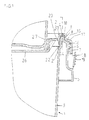
- Fig. 1 shows an injection-molded plastic bucket 1 with snapped lid 2, wherein the outer wall 3 of the Eimers concluding upper edge 4 a flattened area is provided. At the top 4 closes a circumferential and radially outwardly projecting edge 5, to the an outwardly projecting latching edge 6 is formed, the of a circumferential locking edge 7 of the lid with a hook-shaped Projection is under attack.
- the upper edge 4 of the bucket associated with the area of the lid 2 is groove-shaped or channel-shaped, wherein the outer edge 8 of the groove 34 at the two vertically spaced circumferential Ribs 9 of the bucket rests laterally.
- the radial Extension of the ribs 9 is significantly less than the wall thickness of the bucket, here about one third of the same.
- the Ribs 9 are here at the height of the portion 12 of the seal arranged, with the lid even in the absence of these ribs with less or virtually no pretension at this height at the Outer wall of the bucket can rest, which at the same time the Seal is positioned exactly.
- a seal made of an elastic and compressible rubber material integrally molded.
- associated sealing region 12 is arranged at an angle to the vertical, here at an angle of approx. 20 °, whereby the angle also assume values between 5 and 45 ° can, without being limited to.
- the inclined section 12 of the seal 11 is in the snapped condition of the Dekkels at the inside of the bucket top edge 4 subsequent, inwardly sloping slope 13 (see Also Fig. 2,3), whose inclination of the contact surface of the section 12 corresponds to the seal, without being limited thereto to be.
- the lid portion of the section 12 of Seal radially inside surrounds is chamfered executed.
- the outside circumferential edge 5 of the bucket is at the level of Top edge 4 attached, so that the demarcated from the edge 5 Cavity 14 is close to the top edge, d. H. except for about a wall thickness extending.
- the area of the upper edge 4 of the Pail is thus also as a U-shaped circumferential profile designed. As a result, the lid can be optimally braced and laterally occurring forces are absorbed.
- the lid Inboard of the seal 11, the lid has a circumferential Seal web 20 on, the only over a partial area the height sealingly abuts the Eimerinnenwandung, namely in the area of the lower end of the bridge, at about the height of the reinforcing edge 16 and the latching edge is arranged.
- the essentially vertical after Below projecting rib 20 is at the level of an inwardly projecting Paragraph 21 of the bucket inner wall arranged and here slightly vertically spaced therefrom. At lower vertical pressure on the lid sets the rib 20 to paragraph 21.
- the paragraph 21 is turned inwards by a encircling edge 22 limited, instead also individual Projections may be provided, wherein the edge 22 over the Lower edge of the rib 20 protrudes and an inwardly directed Movement of the rib 20 prevents.
- the rib 20 can also be between the edge 22 and the outside adjacent wall portion of the Eimers be recorded in a press fit.
- the rib 20 is slightly inclined outwards so that the sealing area the rib 20, i. the lower end thereof (see Fig. 2) with the cover removed radially outside the container inner wall to come to rest.
- the thickness of the lower edge corresponds here about the rib thickness, preferably more than 1/4 of the same, where it runs slightly conical here. This is at always put on a cover under radial prestress achieved with the container inner wall.
- the area 26 is arranged below the latching edge 6, wherein its outer diameter, as shown, is dimensioned such that a stacking of buckets is possible. This results in projections with triangular cross-section, following a trapezoidal shape are formed below open groove.
- the substantially vertical leg of the U-shaped upper edge 4 goes outwards into a chamfer 15, which a step-shaped paragraph is formed.
- the snap edge 6 is formed, with between snap edge and the paragraph, here at the height of the paragraph, a radially encircling Reinforcement edge 16 is formed, in this Example to the outside at the height of the locking edge 6 concludes and a width corresponding thereto, d. H. vertical extension, having.
- the lower edge of the reinforcing edge 16 is formed according to the latching edge 6, so that the Rastrand 7 of the lid also in the between the edges 6 and 16 arranged groove can intervene, including the upper edge of the latching edge 6 falls obliquely outwards.
- the lid edge is thus in fully snapped on the Outer edge of the latching edge 6 and / or the reinforcing edge 16, whereby together with the sealing web 20 of the upper Tank area is subjected to force on both sides. Especially due to the vertical symmetrical application of force results in a very good tightness. For this also carries the U-shaped configuration of the upper tank area at, the side compressible under a clamping force is. Between bevel 15 and arranged above this Sliding slope 17 of the lid can be a small gap be provided.
- the peripheral edge 5 has below the locking edge 7 a circumferential step shoulder 18, which from the locking edge 7 on protrudes beyond the outer edge of the lid 2, wherein the Retrand 7 sit on the stepped shoulder 18 under tension can or between the curb and step heel also a gap can be provided.
- the stepped shoulder 18 has a tamper-evident closure 19 on, after the removal of the rest of the beach 7 manually grabbed from below and the lid are removed can. It should be noted here that preferably the Cover area between the groove receiving the seal and the catching edge has no significant material weakening, so that between the latching connection and the seal 11 or the inside of the bucket 1 arranged portion of the lid a high stability and thus high tightness given is.
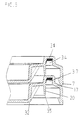
- the outer wall 3 of the bucket has to enable an improved Power transmission with simultaneous stackability of buckets without a lid into each other a conicity or inclination to the outside of less than 3 °, preferably 2 °, wherein even lower inclinations are possible. Furthermore, it is around the forces of stacked buckets with lid in the edge area better able to catch the distance between the bucket center facing side of the wall 25 of the projections and the opposite outer wall of the bucket 27 with only a small Measure game, z. B. with a distance of less than 2 mm, preferably 1 mm.
- the top edge 4 of the bucket edge is two circumferential Ribs 36 provided with the teeth on the Attack underside of the seal 11, and / or next to the ribs 36 in the groove formed between these or outside the same tired of the container edge 4 rest.
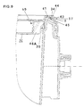
- Fig. 4 is the inside of the bucket wall. 3 arranged circumferential edge 23 of the lid with segments 28, Provided 29 different radial width, resulting in gives an effective stiffening profile to forces on the To catch sealing area of the rib 20 or the seal 11.
- the circumferential extent of the regions 28, 29 amounts to the example a multiple of their width.
- the bevels 24 and vertical wall portions 25 terminate at the same distance from the bucket main axis, wherein the bevel 24 side delimiting areas 29a extend obliquely to the lid circumference.
- the areas 25, 29 and 29a thus limit the projections 25a.
- a lockable Arranged pourer which is about one quarter of the Diameter of the bucket is arranged.
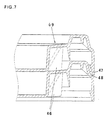
- Fig. 6 shows another embodiment, in which the lid inside projections 49 with substantially vertical Stiffening ribs 46 are provided, which are connected to the outside essentially vertical and essentially horizontal region of the projecting segments 49 connected are and end in front of the circumferential sealing edge 20.
- the stiffening ribs can also up to the sealing edge 20, but preferably not linear abut the sealing edge to seal error due avoiding shrinkage, especially not on Height of the sealing contact area of the sealing rib on the Container interior wall, or with a vertical area, whose vertical extent of the stiffening rib at the level of the inside Edge of the ledge.
- Stiffening ribs 46 may also corresponding to an internal be provided circumferential edge of the lid, the not dissected into protruding and recessed areas.
- the ribs 46 close to the lower edge of the lid portion If necessary, they may also support the lid area 26.
- the sealing ribs 41 exist from the container material and are integrally formed.
- the Container upper edge 40 is here from a radially outer side arranged, circumferential and downwardly projecting web 43 surrounding, which at the radially outwardly projecting circumferential Ribs 9 of the container fits tightly.
- the groove bottom forming horizontal cover portion 44 extends radially outward over the web 43, so that the Abgleitschräge 17th is made steeper than in the previous embodiments. Between web 43 and Abgleitschräge 17 can Stiffening ribs 45 may be provided.
- the Stiffening ribs 46 at the same time the support to the underneath serve lying lid and this line or even punctiform on the top of the internal projections 49th or surrounding edges.
- the sealing rib 20 is in this case spaced from the adjacent lid, If necessary, it can also be supported on it.
- FIG. 8 shows a further embodiment in which the at least one projection 50 at the top of a from the sealing ridge radially inwardly extending and inclined to the container interior sloping portion 51 is formed.
- Area 51 represents here a circumferential edge.
- the projection 50 is executed here web-like, with a variety of webs are integrally formed on the peripheral area.
- the inclined to the container interior sloping portion 51 may also connect directly to the sealing web 20.
- the radially inward flank of the projection can also be inclined run.
- Figure 9 shows a modification of a lid according to the figures 6 and 7 in which the stiffening ribs 46a extend to the Seal web 20 extend and one formed on this Have area whose height is small against the height of the Sealing strip itself.
Landscapes
- Engineering & Computer Science (AREA)
- Mechanical Engineering (AREA)
- Closures For Containers (AREA)
- Table Devices Or Equipment (AREA)
- Packages (AREA)
- Cultivation Receptacles Or Flower-Pots, Or Pots For Seedlings (AREA)
- Lining Or Joining Of Plastics Or The Like (AREA)
Claims (15)
- Réceptacle (1) en matière plastique avec couvercle (2) à enclenchement et avec bordure d'enclenchement (6) agencé sur la région de bord supérieure du réceptacle, destiné à la fixation du couvercle par enclenchement, ledit couvercle présentant une jupe d'étanchement (20) périphérique en dépassement vers le bas et venant en contact avec le côté intérieur du réceptacle, dans lequel au moins une saillie (25a, 49, 50) est prévue sur le couvercle radialement vers l'intérieur vis-à-vis de la jupe d'étanchement (20), cette saillie s'étendant sensiblement en direction radiale et en direction verticale, l'extension verticale de la région respective (29, 46) de la saillie (25a) qui est respectivement limitrophe de la jupe d'étanchement (20) étant petite par rapport à l'extension verticale totale de la saillie et/ou par rapport à l'extension verticale d'une zone de paroi (25) limitrophe radialement à l'intérieur par rapport à la saillie et s'étendant sensiblement perpendiculairement à celle-ci, caractérisé en ce que la zone d'étanchement de la jupe d'étanchement (20) est agencée approximativement à hauteur de la bordure d'enclenchement extérieure (6) ou qu'une nervure de renforcement extérieur périphérique (16) est prévue et en ce que la zone d'étanchement de la jupe d'étanchement (20) est agencée approximativement à hauteur de la nervure de renforcement (16).
- Réceptacle selon la revendication 1, caractérisé en ce que la saillie (25a) comporte des parois latérales (29a) et/ou des goussets (45) mutuellement écartés l'un de l'autre, dont l'extension verticale limitrophe au niveau de la jupe d'étanchement (20) est respectivement petite par rapport à leur extension verticale totale et/ou par rapport à l'extension verticale d'une zone de paroi (25) limitrophe radialement à l'intérieur contre la saillie et s'étendant sensiblement perpendiculairement à celle-ci.
- Réceptacle selon l'une ou l'autre des revendications 1 et 2, caractérisé en ce que la saillie (25a, 49) est agencée à distance radiale de la jupe d'étanchement (20) agencée du côté intérieur du réceptacle.
- Réceptacle selon l'une des revendications 1 à 3, caractérisé en ce que la zone (23) formée sur la jupe d'étanchement (20) est écartée de la zone (35) de la jupe d'étanchement (20) qui assure le plus grand effet d'étanchement.
- Réceptacle selon l'une des revendications 1 à 4, caractérisé en ce que la zone d'étanchement (35) de la jupe d'étanchement (20) est située dans la plage de la hauteur verticale des saillies (25a).
- Réceptacle selon l'une des revendications 1 à 5, caractérisé en ce que ladite au moins une saillie (50) est formée sur le couvercle à hauteur de la face supérieure d'une region (51) qui s'étend radialement vers l'intérieur depuis la jupe d'étanchement (20) et descend de façon inclinée en direction de l'intérieur du réceptacle.
- Réceptacle selon l'une des revendications 1 à 6, caractérisé en ce que le couvercle (2) comprend, additionnellement à la jupe d'étanchement (20), une zone d'étanchement périphérique dans la région de l'arête supérieure (4) du réceptacle.
- Réceptacle selon l'une des revendications 1 à 7, caractérisé en ce qu'il est prévu une zone d'étanchement additionnelle (13), et en ce que des régions du couvercle (23, 29, 46) formées sur la jupe d'étanchement (20) et s'étendant radialement vers l'intérieur son formées sur la jupe d'étanchement (20) à distance verticale de la zone d'étanchement additionnelle (13).
- Réceptacle selon l'une des revendications 1 à 8, caractérisé en ce qu'un talon (21) est formé dans la paroi intérieure du récipient au-dessous de la jupe d'étanchement (20), talon sur lequel la jupe d'étanchement (20) est susceptible de venir s'appuyer par son extrémité libre inférieure.
- Réceptacle selon l'une des revendications 1 à 9, caractérisé en ce qu'il est prévu au niveau de la paroi intérieure du réceptacle un rebord (22) situé radialement à l'intérieur de la jupe d'étanchement périphérique (20) et dépassant vers le haut jusqu'au-delà de l'extrémité inférieure de la jupe d'étanchement (20).
- Réceptacle selon l'une des revendications 1 à 10, caractérisé en ce qu'au bord du réceptacle et dans la région de l'arête supérieure du réceptacle (4) est formée au moins une nervure de renforcement (16) qui dépasse radialement.
- Réceptacle selon l'une des revendications 1 à 11, caractérisé en ce qu'il est prévu une zone d'étanchement additionnelle entre l'arête supérieure du réceptacle et le couvercle (2) avec un joint périphérique (11) en un matériau de plus forte élasticité que celui du réceptacle (1) et/ou du couvercle (2).
- Réceptacle selon l'une des revendications 1 à 12, caractérisé en ce qu'il est prévu au niveau de l'arête supérieure (4) du réceptacle et radialement à l'intérieur une zone (13) qui descend en oblique vers la paroi intérieure du réceptacle et qui s'étend sous un angle aigu par rapport à l'axe principal du réceptacle.
- Réceptacle selon l'une des revendications 1 à 13, caractérisé en ce que, au niveau de la zone extérieure voisine de l'arête supérieure (4) du réceptacle, est formée une nervure d'appui (9) en dépassement radial vers l'extérieur pour l'appui latéral du couvercle.
- Réceptacle selon l' une des revendications 1 à 14, caractérisé en ce qu'il est prévu dans la région supérieure du réceptacle (1) et du côté extérieur un bord (5) périphérique tiré vers le bas, lequel est mis en place dans la région de l'arête supérieure (4) du réceptacle.
Priority Applications (1)
| Application Number | Priority Date | Filing Date | Title |
|---|---|---|---|
| DK01913593T DK1268295T3 (da) | 2001-02-08 | 2001-02-08 | Kunststofbeholder med låsbart låg og indvendigt anordnet tætningsprofil |
Applications Claiming Priority (3)
| Application Number | Priority Date | Filing Date | Title |
|---|---|---|---|
| DE20006095U | 2000-04-01 | ||
| DE20006095U DE20006095U1 (de) | 2000-04-01 | 2000-04-01 | Kunststoffbehälter mit aufrastbarem Deckel und behälterinnenseitig angeordnetem Dichtungssteg |
| PCT/DE2001/000478 WO2001074680A1 (fr) | 2000-04-01 | 2001-02-08 | Contenant en plastique avec couvercle encliquetable et arete d'etancheite a l'interieur du contenant |
Publications (2)
| Publication Number | Publication Date |
|---|---|
| EP1268295A1 EP1268295A1 (fr) | 2003-01-02 |
| EP1268295B1 true EP1268295B1 (fr) | 2004-11-03 |
Family
ID=7939721
Family Applications (1)
| Application Number | Title | Priority Date | Filing Date |
|---|---|---|---|
| EP01913593A Expired - Lifetime EP1268295B1 (fr) | 2000-04-01 | 2001-02-08 | Contenant en plastique avec couvercle encliquetable et arete d'etancheite a l'interieur du contenant |
Country Status (9)
| Country | Link |
|---|---|
| US (1) | US6845877B2 (fr) |
| EP (1) | EP1268295B1 (fr) |
| AT (1) | ATE281367T1 (fr) |
| AU (1) | AU2001239162A1 (fr) |
| DE (3) | DE20006095U1 (fr) |
| ES (1) | ES2232603T3 (fr) |
| FR (1) | FR2808509B3 (fr) |
| PT (1) | PT1268295E (fr) |
| WO (1) | WO2001074680A1 (fr) |
Families Citing this family (38)
| Publication number | Priority date | Publication date | Assignee | Title |
|---|---|---|---|---|
| DE20006094U1 (de) | 2000-04-01 | 2000-09-14 | Jokey Plastik Gummersbach GmbH, 51645 Gummersbach | Kunststoffbehälter mit einrastbarem Deckel |
| DE10140255A1 (de) * | 2001-08-07 | 2003-02-27 | Huber Westform Gmbh & Co | Behälter mit Deckel |
| WO2004045978A1 (fr) * | 2002-11-15 | 2004-06-03 | Schoeller Wavin Systems Services Gmbh | Seau comportant une fermeture de securite |
| GB2398267B (en) * | 2003-02-12 | 2006-10-18 | Gaydog Ltd | Container and method and apparatuus for making the same |
| WO2004083049A1 (fr) * | 2003-03-13 | 2004-09-30 | Fort James Corporation | Recipient de stockage d'aliment pouvant passer au four a micro-ondes et presentant un indicateur de fraicheur et un event a vapeur |
| DE20319163U1 (de) * | 2003-12-11 | 2004-04-15 | Groku Kunststoffe Gmbh | Mit einem abnehmbaren Deckel verschlossener Behälter |
| DE102004049225B4 (de) | 2004-09-24 | 2017-03-02 | Ardagh Mp Group Netherlands B.V. | Behälterverschluss für Gefahrengut |
| JP4945552B2 (ja) * | 2005-03-11 | 2012-06-06 | ジェイティーアイ スヌース アーベー | 箱と蓋 |
| US20060237463A1 (en) * | 2005-04-21 | 2006-10-26 | Tony Riviezzo | Component seal for plastic tanks |
| US8322530B2 (en) | 2006-02-09 | 2012-12-04 | Rubbermaid Incorporated | Storage container and container system |
| US7963419B2 (en) | 2006-02-23 | 2011-06-21 | Bway Corporation | Lid and container |
| US8181819B2 (en) | 2006-02-23 | 2012-05-22 | Bway Corporation | Lid and container |
| US7815067B2 (en) * | 2006-03-31 | 2010-10-19 | Helen Of Troy Limited | Container with sealable lid |
| DE202006010401U1 (de) * | 2006-07-05 | 2006-08-31 | Ewald Euscher Gmbh & Co. Kg | Ventilteller für eine Sprühdose |
| ES2348053T3 (es) * | 2006-11-20 | 2010-11-29 | Superfos A/S | Metodo para producir una gama de productos de envase de plastico moldeados por inyeccion que incluyen un cubo y una tapa. |
| US7896185B2 (en) | 2007-03-06 | 2011-03-01 | Kw Plastics | Plastic container having gasketless seal |
| US8047398B2 (en) * | 2007-06-22 | 2011-11-01 | Kraft Foods Global Brands Llc | Snap overcap closure for a container |
| DE202007009414U1 (de) * | 2007-07-04 | 2008-11-13 | pfm Produkte für die Medizin AG | Vorevakuierbarer oder vorevakuierter Behälter für medizinische Zwecke |
| US20090294322A1 (en) * | 2008-06-02 | 2009-12-03 | Baltz Kyle L | Pail with skirt and lid |
| US7922028B2 (en) * | 2009-02-25 | 2011-04-12 | Rehrig Pacific Company | Pail with lid and flashed lip |
| US8708176B2 (en) * | 2009-12-30 | 2014-04-29 | Tim Andis | Quick access closure apparatus and methods of use |
| US8925755B2 (en) | 2010-04-13 | 2015-01-06 | Ipl, Inc. | Tamper evident system and method |
| US9340330B2 (en) | 2010-06-24 | 2016-05-17 | S. C. Johnson & Son, Inc. | Storage container lids |
| US8777046B2 (en) * | 2010-10-08 | 2014-07-15 | Berry Plastics Corporation | Drink cup with rolled brim |
| US8651312B2 (en) * | 2011-04-08 | 2014-02-18 | Berry Plastics Corporation | Canister |
| DE202011100541U1 (de) * | 2011-05-11 | 2012-08-14 | Pöppelmann Holding GmbH & Co. KG | Verpackungsbehältnis |
| USD706131S1 (en) | 2011-10-10 | 2014-06-03 | Kraft Foods Group Brands Llc | Container |
| DE102012215121A1 (de) * | 2012-08-24 | 2014-05-28 | Aesculap Ag | Zentrierhilfe für Behälterdeckel |
| US9205951B1 (en) * | 2014-07-24 | 2015-12-08 | Josephine E. Roman | All-in-one stackable bulletin board caddy |
| US9522763B2 (en) * | 2014-07-24 | 2016-12-20 | Josephine E. Roman | All-in-one stackable bulletin board caddy |
| WO2016046838A2 (fr) | 2014-09-25 | 2016-03-31 | Mold-Tek Packaging Limited | Systèmes de fermeture de seau étanches inviolables |
| US9669930B2 (en) * | 2015-04-01 | 2017-06-06 | Norduyn Inc. | Galley cart with multi-capacity support |
| DK179963B1 (en) | 2018-04-16 | 2019-11-06 | Rpc Superfos A/S | INJECTED PACKAGING WITH A CONTAINER WITH A FOLDED TOP AND METHOD FOR PREPARING SUCH A PACKAGING |
| CN108910265A (zh) * | 2018-08-01 | 2018-11-30 | 常州市诚鑫环保科技有限公司 | 纸塑汤杯盖 |
| US20220024652A1 (en) * | 2019-02-26 | 2022-01-27 | Bway Corporation | Container and seal assembly |
| US11092119B1 (en) | 2019-05-01 | 2021-08-17 | S&B Filters, Inc. | Viewing port for an airbox on an intake tube |
| US11753214B2 (en) | 2020-07-29 | 2023-09-12 | Saint-Gobain Performance Plastics Corporation | Closure, combination container and closure system, and method of using the same |
| FR3130769A1 (fr) * | 2021-12-17 | 2023-06-23 | Cm Finances | Couvercle destiné à fermer un récipient |
Family Cites Families (22)
| Publication number | Priority date | Publication date | Assignee | Title |
|---|---|---|---|---|
| US3510023A (en) * | 1968-08-14 | 1970-05-05 | Inland Steel Co | Plastic container and lid therefor |
| NL6918704A (fr) * | 1969-12-12 | 1971-06-15 | ||
| DE2226217A1 (de) * | 1972-05-30 | 1973-12-13 | Wilhelm Hammes | Spundfass aus kunststoff mit einer oder mehreren spundoeffnungen |
| DE3108949A1 (de) * | 1980-12-05 | 1982-07-08 | Kunststoffwerk Eugen Saier Gmbh & Co, 7297 Alpirsbach | "behaelter mit einem deckel" |
| DE3032366A1 (de) * | 1980-08-28 | 1982-04-08 | Kunststoffwerk Eugen Saier Gmbh & Co, 7297 Alpirsbach | Behaelter mit einem deckel |
| DE8131915U1 (de) * | 1981-10-31 | 1982-02-25 | Mauser-Werke GmbH, 5040 Brühl | Hobbock |
| DE8429165U1 (de) * | 1984-10-04 | 1985-01-03 | Achterberg, Willem Jan, Veenendaal | Einwegbehaelter fuer krankenhausabfaelle |
| DE3829778C1 (fr) * | 1988-09-02 | 1989-08-10 | Brauckmann & Proebsting Gmbh & Co Kg, 5880 Luedenscheid, De | |
| US5035344A (en) * | 1990-01-31 | 1991-07-30 | Gary Christopher | Closure for portable container |
| FR2665688A1 (fr) * | 1990-08-13 | 1992-02-14 | Cmb Packaging Sa | Couvercle en matiere plastique souple pour recipient a bord arrondi. |
| US5143219A (en) * | 1991-04-08 | 1992-09-01 | Yates Jr George | Stackable container with protected lid seal |
| EP0600127A1 (fr) * | 1992-12-01 | 1994-06-08 | Landgraf, Rainer Dipl.jur.Dipl.agr | Récipient empilable |
| DE4306982C2 (de) * | 1993-03-05 | 1998-08-20 | Jokey Plastik Wipperfuerth | Stapelbarer Deckel für einen Eimer |
| DE9403122U1 (de) * | 1994-02-25 | 1994-04-28 | Jokey-Plastik Wipperfürth GmbH, 51688 Wipperfürth | Spritzgegossener Kunststoffeimer mit stapelbarem Deckel |
| WO1995023096A1 (fr) | 1994-02-25 | 1995-08-31 | Jokey Plastik Wipperfürth GmbH | Recipient en plastique moule par injection a bord unique et dote d'un couvercle encliquetable |
| DK171723B1 (da) * | 1994-11-25 | 1997-04-14 | Erik Bock | Faldsikkert plastlåg til beholder |
| US5540349A (en) * | 1995-03-07 | 1996-07-30 | Bennett Industries, Inc. | Container closure with separable wall segments |
| DE19705717A1 (de) * | 1997-02-14 | 1998-08-20 | Bericap Gmbh & Co Kg | Kunststoffschraubverschluß |
| US5915575A (en) * | 1997-05-28 | 1999-06-29 | M&M Industries, Inc. | Secure lid and open head container assembly for liquids |
| US5810190A (en) * | 1997-06-27 | 1998-09-22 | Atlanta Polyseal Ltd. | Plastic bung seal |
| US6006942A (en) * | 1997-10-02 | 1999-12-28 | M&M Industries, Inc. | Open head container and lid assembly |
| DE19855361C2 (de) * | 1998-12-01 | 2003-05-28 | Jokey Plastik Wipperfuerth | Kunststoffbehälter mit Deckel |
-
2000
- 2000-04-01 DE DE20006095U patent/DE20006095U1/de not_active Expired - Lifetime
-
2001
- 2001-02-08 AU AU2001239162A patent/AU2001239162A1/en not_active Abandoned
- 2001-02-08 PT PT01913593T patent/PT1268295E/pt unknown
- 2001-02-08 AT AT01913593T patent/ATE281367T1/de active
- 2001-02-08 ES ES01913593T patent/ES2232603T3/es not_active Expired - Lifetime
- 2001-02-08 DE DE50104395T patent/DE50104395D1/de not_active Expired - Lifetime
- 2001-02-08 WO PCT/DE2001/000478 patent/WO2001074680A1/fr active IP Right Grant
- 2001-02-08 EP EP01913593A patent/EP1268295B1/fr not_active Expired - Lifetime
- 2001-02-08 DE DE10191221T patent/DE10191221D2/de not_active Expired - Fee Related
- 2001-03-29 FR FR0104294A patent/FR2808509B3/fr not_active Expired - Fee Related
- 2001-04-02 US US09/822,850 patent/US6845877B2/en not_active Expired - Lifetime
Also Published As
| Publication number | Publication date |
|---|---|
| EP1268295A1 (fr) | 2003-01-02 |
| US20020175172A1 (en) | 2002-11-28 |
| ATE281367T1 (de) | 2004-11-15 |
| FR2808509A3 (fr) | 2001-11-09 |
| DE20006095U1 (de) | 2000-09-14 |
| US6845877B2 (en) | 2005-01-25 |
| PT1268295E (pt) | 2005-03-31 |
| AU2001239162A1 (en) | 2001-10-15 |
| WO2001074680A1 (fr) | 2001-10-11 |
| DE10191221D2 (de) | 2003-06-05 |
| DE50104395D1 (de) | 2004-12-09 |
| ES2232603T3 (es) | 2005-06-01 |
| FR2808509B3 (fr) | 2002-04-26 |
Similar Documents
| Publication | Publication Date | Title |
|---|---|---|
| EP1268295B1 (fr) | Contenant en plastique avec couvercle encliquetable et arete d'etancheite a l'interieur du contenant | |
| EP1268289B1 (fr) | Contenant en matiere plastique dote d'un couvercle encliquetable | |
| EP1268286B1 (fr) | Recipient en matiere plastique comprenant un couvercle encliquetable | |
| DE1942417A1 (de) | Behaelter | |
| EP2036838A1 (fr) | Agencement de couvercle pour un récipient à liquide | |
| WO2008095478A2 (fr) | Récipient à couvercle et procédé de fabrication dudit récipient | |
| EP1058654B1 (fr) | Couvercle plastique a obturateur plastique | |
| EP1670692B1 (fr) | Contenant | |
| EP1135303B1 (fr) | Contenant en matiere plastique comportant un couvercle | |
| EP3153422A1 (fr) | Recipient avec couvercle | |
| EP3377416B1 (fr) | Réceptacle en matière plastique | |
| WO1995023096A1 (fr) | Recipient en plastique moule par injection a bord unique et dote d'un couvercle encliquetable | |
| EP0343680B1 (fr) | Poubelle | |
| DE202005006306U1 (de) | Behälter mit Abrolleinrichtung und Abrolleinrichtung | |
| DE102015108403B3 (de) | Getränkedosenverschluss sowie Doseneinheit aus Getränkedose und Verschluss | |
| DE202018105911U1 (de) | Stapelbarer Behälter | |
| EP4001141B1 (fr) | Bouchons pour un récipient | |
| DE7717675U1 (de) | Gefaess fuer Streichmasse | |
| DE2328214A1 (de) | Behaelter mit einem auf seinen oeffnungswulst aufsetzbaren deckel | |
| WO2002047996A1 (fr) | Recipient a couvercle encliquetable | |
| DE202010007232U1 (de) | Behälter | |
| WO2020079076A2 (fr) | Récipient empilable | |
| DE3518251A1 (de) | Deckel fuer behaelter | |
| DE9313574U1 (de) | Verpackungsbox aus Kunststoff | |
| EP3202590A1 (fr) | Grille d'essorage |
Legal Events
| Date | Code | Title | Description |
|---|---|---|---|
| PUAI | Public reference made under article 153(3) epc to a published international application that has entered the european phase |
Free format text: ORIGINAL CODE: 0009012 |
|
| 17P | Request for examination filed |
Effective date: 20020618 |
|
| AK | Designated contracting states |
Kind code of ref document: A1 Designated state(s): AT BE CH CY DE DK ES FI FR GB GR IE IT LI LU MC NL PT SE TR |
|
| AX | Request for extension of the european patent |
Free format text: AL;LT;LV;MK;RO;SI |
|
| GRAP | Despatch of communication of intention to grant a patent |
Free format text: ORIGINAL CODE: EPIDOSNIGR1 |
|
| GRAS | Grant fee paid |
Free format text: ORIGINAL CODE: EPIDOSNIGR3 |
|
| GRAA | (expected) grant |
Free format text: ORIGINAL CODE: 0009210 |
|
| AK | Designated contracting states |
Kind code of ref document: B1 Designated state(s): AT BE CH CY DE DK ES FI FR GB GR IE IT LI LU MC NL PT SE TR |
|
| REG | Reference to a national code |
Ref country code: GB Ref legal event code: FG4D Free format text: NOT ENGLISH |
|
| REG | Reference to a national code |
Ref country code: CH Ref legal event code: EP |
|
| REF | Corresponds to: |
Ref document number: 50104395 Country of ref document: DE Date of ref document: 20041209 Kind code of ref document: P |
|
| REG | Reference to a national code |
Ref country code: IE Ref legal event code: FG4D Free format text: GERMAN |
|
| PG25 | Lapsed in a contracting state [announced via postgrant information from national office to epo] |
Ref country code: CY Free format text: LAPSE BECAUSE OF FAILURE TO SUBMIT A TRANSLATION OF THE DESCRIPTION OR TO PAY THE FEE WITHIN THE PRESCRIBED TIME-LIMIT Effective date: 20050208 |
|
| REG | Reference to a national code |
Ref country code: SE Ref legal event code: TRGR |
|
| PG25 | Lapsed in a contracting state [announced via postgrant information from national office to epo] |
Ref country code: MC Free format text: LAPSE BECAUSE OF NON-PAYMENT OF DUE FEES Effective date: 20050228 |
|
| REG | Reference to a national code |
Ref country code: CH Ref legal event code: NV Representative=s name: KATZAROV S.A. |
|
| REG | Reference to a national code |
Ref country code: DK Ref legal event code: T3 |
|
| REG | Reference to a national code |
Ref country code: GR Ref legal event code: EP Ref document number: 20050400337 Country of ref document: GR |
|
| REG | Reference to a national code |
Ref country code: PT Ref legal event code: SC4A Free format text: AVAILABILITY OF NATIONAL TRANSLATION Effective date: 20050114 |
|
| GBT | Gb: translation of ep patent filed (gb section 77(6)(a)/1977) |
Effective date: 20050310 |
|
| REG | Reference to a national code |
Ref country code: ES Ref legal event code: FG2A Ref document number: 2232603 Country of ref document: ES Kind code of ref document: T3 |
|
| PLBE | No opposition filed within time limit |
Free format text: ORIGINAL CODE: 0009261 |
|
| STAA | Information on the status of an ep patent application or granted ep patent |
Free format text: STATUS: NO OPPOSITION FILED WITHIN TIME LIMIT |
|
| 26N | No opposition filed |
Effective date: 20050804 |
|
| ET | Fr: translation filed | ||
| REG | Reference to a national code |
Ref country code: FR Ref legal event code: PLFP Year of fee payment: 15 |
|
| REG | Reference to a national code |
Ref country code: FR Ref legal event code: PLFP Year of fee payment: 16 |
|
| REG | Reference to a national code |
Ref country code: FR Ref legal event code: PLFP Year of fee payment: 17 |
|
| REG | Reference to a national code |
Ref country code: FR Ref legal event code: PLFP Year of fee payment: 18 |
|
| REG | Reference to a national code |
Ref country code: CH Ref legal event code: PCAR Free format text: NEW ADDRESS: AVENUE DES MORGINES 12, 1213 PETIT-LANCY (CH) |
|
| PGFP | Annual fee paid to national office [announced via postgrant information from national office to epo] |
Ref country code: LU Payment date: 20180221 Year of fee payment: 18 Ref country code: NL Payment date: 20180221 Year of fee payment: 18 |
|
| PGFP | Annual fee paid to national office [announced via postgrant information from national office to epo] |
Ref country code: DK Payment date: 20180221 Year of fee payment: 18 Ref country code: GB Payment date: 20180221 Year of fee payment: 18 Ref country code: ES Payment date: 20180322 Year of fee payment: 18 Ref country code: FI Payment date: 20180216 Year of fee payment: 18 Ref country code: CH Payment date: 20180221 Year of fee payment: 18 |
|
| PGFP | Annual fee paid to national office [announced via postgrant information from national office to epo] |
Ref country code: IE Payment date: 20180220 Year of fee payment: 18 Ref country code: SE Payment date: 20180222 Year of fee payment: 18 Ref country code: BE Payment date: 20180221 Year of fee payment: 18 Ref country code: IT Payment date: 20180221 Year of fee payment: 18 Ref country code: FR Payment date: 20180226 Year of fee payment: 18 Ref country code: GR Payment date: 20180221 Year of fee payment: 18 Ref country code: TR Payment date: 20180207 Year of fee payment: 18 Ref country code: PT Payment date: 20180131 Year of fee payment: 18 Ref country code: AT Payment date: 20180220 Year of fee payment: 18 |
|
| PGFP | Annual fee paid to national office [announced via postgrant information from national office to epo] |
Ref country code: DE Payment date: 20180424 Year of fee payment: 18 |
|
| REG | Reference to a national code |
Ref country code: DE Ref legal event code: R119 Ref document number: 50104395 Country of ref document: DE |
|
| REG | Reference to a national code |
Ref country code: DK Ref legal event code: EBP Effective date: 20190228 |
|
| REG | Reference to a national code |
Ref country code: CH Ref legal event code: PL |
|
| REG | Reference to a national code |
Ref country code: SE Ref legal event code: EUG |
|
| REG | Reference to a national code |
Ref country code: NL Ref legal event code: MM Effective date: 20190301 |
|
| REG | Reference to a national code |
Ref country code: AT Ref legal event code: MM01 Ref document number: 281367 Country of ref document: AT Kind code of ref document: T Effective date: 20190208 |
|
| GBPC | Gb: european patent ceased through non-payment of renewal fee |
Effective date: 20190208 |
|
| PG25 | Lapsed in a contracting state [announced via postgrant information from national office to epo] |
Ref country code: FI Free format text: LAPSE BECAUSE OF NON-PAYMENT OF DUE FEES Effective date: 20190208 Ref country code: PT Free format text: LAPSE BECAUSE OF NON-PAYMENT OF DUE FEES Effective date: 20190808 Ref country code: SE Free format text: LAPSE BECAUSE OF NON-PAYMENT OF DUE FEES Effective date: 20190209 Ref country code: LU Free format text: LAPSE BECAUSE OF NON-PAYMENT OF DUE FEES Effective date: 20190208 |
|
| REG | Reference to a national code |
Ref country code: BE Ref legal event code: MM Effective date: 20190228 |
|
| REG | Reference to a national code |
Ref country code: IE Ref legal event code: MM4A |
|
| PG25 | Lapsed in a contracting state [announced via postgrant information from national office to epo] |
Ref country code: GR Free format text: LAPSE BECAUSE OF NON-PAYMENT OF DUE FEES Effective date: 20190904 |
|
| PG25 | Lapsed in a contracting state [announced via postgrant information from national office to epo] |
Ref country code: CH Free format text: LAPSE BECAUSE OF NON-PAYMENT OF DUE FEES Effective date: 20190228 Ref country code: LI Free format text: LAPSE BECAUSE OF NON-PAYMENT OF DUE FEES Effective date: 20190228 Ref country code: AT Free format text: LAPSE BECAUSE OF NON-PAYMENT OF DUE FEES Effective date: 20190208 |
|
| PG25 | Lapsed in a contracting state [announced via postgrant information from national office to epo] |
Ref country code: NL Free format text: LAPSE BECAUSE OF NON-PAYMENT OF DUE FEES Effective date: 20190301 Ref country code: DK Free format text: LAPSE BECAUSE OF NON-PAYMENT OF DUE FEES Effective date: 20190228 Ref country code: GB Free format text: LAPSE BECAUSE OF NON-PAYMENT OF DUE FEES Effective date: 20190208 Ref country code: DE Free format text: LAPSE BECAUSE OF NON-PAYMENT OF DUE FEES Effective date: 20190903 Ref country code: IE Free format text: LAPSE BECAUSE OF NON-PAYMENT OF DUE FEES Effective date: 20190208 |
|
| PG25 | Lapsed in a contracting state [announced via postgrant information from national office to epo] |
Ref country code: BE Free format text: LAPSE BECAUSE OF NON-PAYMENT OF DUE FEES Effective date: 20190228 Ref country code: FR Free format text: LAPSE BECAUSE OF NON-PAYMENT OF DUE FEES Effective date: 20190228 Ref country code: IT Free format text: LAPSE BECAUSE OF NON-PAYMENT OF DUE FEES Effective date: 20190208 |
|
| REG | Reference to a national code |
Ref country code: ES Ref legal event code: FD2A Effective date: 20200327 |
|
| PG25 | Lapsed in a contracting state [announced via postgrant information from national office to epo] |
Ref country code: ES Free format text: LAPSE BECAUSE OF NON-PAYMENT OF DUE FEES Effective date: 20190209 |
|
| PG25 | Lapsed in a contracting state [announced via postgrant information from national office to epo] |
Ref country code: TR Free format text: LAPSE BECAUSE OF NON-PAYMENT OF DUE FEES Effective date: 20190208 |