EP1268295B1 - Plastic container comprising a locking lid and a sealing rib located inside the container - Google Patents
Plastic container comprising a locking lid and a sealing rib located inside the container Download PDFInfo
- Publication number
- EP1268295B1 EP1268295B1 EP01913593A EP01913593A EP1268295B1 EP 1268295 B1 EP1268295 B1 EP 1268295B1 EP 01913593 A EP01913593 A EP 01913593A EP 01913593 A EP01913593 A EP 01913593A EP 1268295 B1 EP1268295 B1 EP 1268295B1
- Authority
- EP
- European Patent Office
- Prior art keywords
- container
- lid
- sealing
- edge
- area
- Prior art date
- Legal status (The legal status is an assumption and is not a legal conclusion. Google has not performed a legal analysis and makes no representation as to the accuracy of the status listed.)
- Expired - Lifetime
Links
Images


Classifications
-
- B—PERFORMING OPERATIONS; TRANSPORTING
- B65—CONVEYING; PACKING; STORING; HANDLING THIN OR FILAMENTARY MATERIAL
- B65D—CONTAINERS FOR STORAGE OR TRANSPORT OF ARTICLES OR MATERIALS, e.g. BAGS, BARRELS, BOTTLES, BOXES, CANS, CARTONS, CRATES, DRUMS, JARS, TANKS, HOPPERS, FORWARDING CONTAINERS; ACCESSORIES, CLOSURES, OR FITTINGS THEREFOR; PACKAGING ELEMENTS; PACKAGES
- B65D43/00—Lids or covers for rigid or semi-rigid containers
- B65D43/02—Removable lids or covers
- B65D43/0202—Removable lids or covers without integral tamper element
- B65D43/0204—Removable lids or covers without integral tamper element secured by snapping over beads or projections
- B65D43/0212—Removable lids or covers without integral tamper element secured by snapping over beads or projections only on the outside, or a part turned to the outside, of the mouth
-
- B—PERFORMING OPERATIONS; TRANSPORTING
- B65—CONVEYING; PACKING; STORING; HANDLING THIN OR FILAMENTARY MATERIAL
- B65D—CONTAINERS FOR STORAGE OR TRANSPORT OF ARTICLES OR MATERIALS, e.g. BAGS, BARRELS, BOTTLES, BOXES, CANS, CARTONS, CRATES, DRUMS, JARS, TANKS, HOPPERS, FORWARDING CONTAINERS; ACCESSORIES, CLOSURES, OR FITTINGS THEREFOR; PACKAGING ELEMENTS; PACKAGES
- B65D21/00—Nestable, stackable or joinable containers; Containers of variable capacity
- B65D21/02—Containers specially shaped, or provided with fittings or attachments, to facilitate nesting, stacking, or joining together
- B65D21/0209—Containers specially shaped, or provided with fittings or attachments, to facilitate nesting, stacking, or joining together stackable or joined together one-upon-the-other in the upright or upside-down position
- B65D21/0217—Containers with a closure presenting stacking elements
- B65D21/0219—Containers with a closure presenting stacking elements the closure presenting projecting peripheral elements receiving or surrounding the bottom or peripheral elements projecting from the bottom of a superimposed container
-
- B—PERFORMING OPERATIONS; TRANSPORTING
- B65—CONVEYING; PACKING; STORING; HANDLING THIN OR FILAMENTARY MATERIAL
- B65D—CONTAINERS FOR STORAGE OR TRANSPORT OF ARTICLES OR MATERIALS, e.g. BAGS, BARRELS, BOTTLES, BOXES, CANS, CARTONS, CRATES, DRUMS, JARS, TANKS, HOPPERS, FORWARDING CONTAINERS; ACCESSORIES, CLOSURES, OR FITTINGS THEREFOR; PACKAGING ELEMENTS; PACKAGES
- B65D2401/00—Tamper-indicating means
- B65D2401/10—Tearable part of the container
-
- B—PERFORMING OPERATIONS; TRANSPORTING
- B65—CONVEYING; PACKING; STORING; HANDLING THIN OR FILAMENTARY MATERIAL
- B65D—CONTAINERS FOR STORAGE OR TRANSPORT OF ARTICLES OR MATERIALS, e.g. BAGS, BARRELS, BOTTLES, BOXES, CANS, CARTONS, CRATES, DRUMS, JARS, TANKS, HOPPERS, FORWARDING CONTAINERS; ACCESSORIES, CLOSURES, OR FITTINGS THEREFOR; PACKAGING ELEMENTS; PACKAGES
- B65D2543/00—Lids or covers essentially for box-like containers
- B65D2543/00009—Details of lids or covers for rigid or semi-rigid containers
- B65D2543/00018—Overall construction of the lid
- B65D2543/00027—Stackable lids or covers
-
- B—PERFORMING OPERATIONS; TRANSPORTING
- B65—CONVEYING; PACKING; STORING; HANDLING THIN OR FILAMENTARY MATERIAL
- B65D—CONTAINERS FOR STORAGE OR TRANSPORT OF ARTICLES OR MATERIALS, e.g. BAGS, BARRELS, BOTTLES, BOXES, CANS, CARTONS, CRATES, DRUMS, JARS, TANKS, HOPPERS, FORWARDING CONTAINERS; ACCESSORIES, CLOSURES, OR FITTINGS THEREFOR; PACKAGING ELEMENTS; PACKAGES
- B65D2543/00—Lids or covers essentially for box-like containers
- B65D2543/00009—Details of lids or covers for rigid or semi-rigid containers
- B65D2543/00018—Overall construction of the lid
- B65D2543/00064—Shape of the outer periphery
- B65D2543/00074—Shape of the outer periphery curved
- B65D2543/00092—Shape of the outer periphery curved circular
-
- B—PERFORMING OPERATIONS; TRANSPORTING
- B65—CONVEYING; PACKING; STORING; HANDLING THIN OR FILAMENTARY MATERIAL
- B65D—CONTAINERS FOR STORAGE OR TRANSPORT OF ARTICLES OR MATERIALS, e.g. BAGS, BARRELS, BOTTLES, BOXES, CANS, CARTONS, CRATES, DRUMS, JARS, TANKS, HOPPERS, FORWARDING CONTAINERS; ACCESSORIES, CLOSURES, OR FITTINGS THEREFOR; PACKAGING ELEMENTS; PACKAGES
- B65D2543/00—Lids or covers essentially for box-like containers
- B65D2543/00009—Details of lids or covers for rigid or semi-rigid containers
- B65D2543/00018—Overall construction of the lid
- B65D2543/0025—Multi-position closures
-
- B—PERFORMING OPERATIONS; TRANSPORTING
- B65—CONVEYING; PACKING; STORING; HANDLING THIN OR FILAMENTARY MATERIAL
- B65D—CONTAINERS FOR STORAGE OR TRANSPORT OF ARTICLES OR MATERIALS, e.g. BAGS, BARRELS, BOTTLES, BOXES, CANS, CARTONS, CRATES, DRUMS, JARS, TANKS, HOPPERS, FORWARDING CONTAINERS; ACCESSORIES, CLOSURES, OR FITTINGS THEREFOR; PACKAGING ELEMENTS; PACKAGES
- B65D2543/00—Lids or covers essentially for box-like containers
- B65D2543/00009—Details of lids or covers for rigid or semi-rigid containers
- B65D2543/00018—Overall construction of the lid
- B65D2543/00259—Materials used
- B65D2543/00296—Plastic
-
- B—PERFORMING OPERATIONS; TRANSPORTING
- B65—CONVEYING; PACKING; STORING; HANDLING THIN OR FILAMENTARY MATERIAL
- B65D—CONTAINERS FOR STORAGE OR TRANSPORT OF ARTICLES OR MATERIALS, e.g. BAGS, BARRELS, BOTTLES, BOXES, CANS, CARTONS, CRATES, DRUMS, JARS, TANKS, HOPPERS, FORWARDING CONTAINERS; ACCESSORIES, CLOSURES, OR FITTINGS THEREFOR; PACKAGING ELEMENTS; PACKAGES
- B65D2543/00—Lids or covers essentially for box-like containers
- B65D2543/00009—Details of lids or covers for rigid or semi-rigid containers
- B65D2543/00342—Central part of the lid
- B65D2543/00398—Reinforcing ribs in the central part of the closure
- B65D2543/00407—Reinforcing ribs in the central part of the closure radial
-
- B—PERFORMING OPERATIONS; TRANSPORTING
- B65—CONVEYING; PACKING; STORING; HANDLING THIN OR FILAMENTARY MATERIAL
- B65D—CONTAINERS FOR STORAGE OR TRANSPORT OF ARTICLES OR MATERIALS, e.g. BAGS, BARRELS, BOTTLES, BOXES, CANS, CARTONS, CRATES, DRUMS, JARS, TANKS, HOPPERS, FORWARDING CONTAINERS; ACCESSORIES, CLOSURES, OR FITTINGS THEREFOR; PACKAGING ELEMENTS; PACKAGES
- B65D2543/00—Lids or covers essentially for box-like containers
- B65D2543/00009—Details of lids or covers for rigid or semi-rigid containers
- B65D2543/00444—Contact between the container and the lid
- B65D2543/00481—Contact between the container and the lid on the inside or the outside of the container
- B65D2543/0049—Contact between the container and the lid on the inside or the outside of the container on the inside, or a part turned to the inside of the mouth of the container
- B65D2543/005—Contact between the container and the lid on the inside or the outside of the container on the inside, or a part turned to the inside of the mouth of the container both cup and skirt
-
- B—PERFORMING OPERATIONS; TRANSPORTING
- B65—CONVEYING; PACKING; STORING; HANDLING THIN OR FILAMENTARY MATERIAL
- B65D—CONTAINERS FOR STORAGE OR TRANSPORT OF ARTICLES OR MATERIALS, e.g. BAGS, BARRELS, BOTTLES, BOXES, CANS, CARTONS, CRATES, DRUMS, JARS, TANKS, HOPPERS, FORWARDING CONTAINERS; ACCESSORIES, CLOSURES, OR FITTINGS THEREFOR; PACKAGING ELEMENTS; PACKAGES
- B65D2543/00—Lids or covers essentially for box-like containers
- B65D2543/00009—Details of lids or covers for rigid or semi-rigid containers
- B65D2543/00444—Contact between the container and the lid
- B65D2543/00481—Contact between the container and the lid on the inside or the outside of the container
- B65D2543/00537—Contact between the container and the lid on the inside or the outside of the container on the outside, or a part turned to the outside of the mouth of the container
-
- B—PERFORMING OPERATIONS; TRANSPORTING
- B65—CONVEYING; PACKING; STORING; HANDLING THIN OR FILAMENTARY MATERIAL
- B65D—CONTAINERS FOR STORAGE OR TRANSPORT OF ARTICLES OR MATERIALS, e.g. BAGS, BARRELS, BOTTLES, BOXES, CANS, CARTONS, CRATES, DRUMS, JARS, TANKS, HOPPERS, FORWARDING CONTAINERS; ACCESSORIES, CLOSURES, OR FITTINGS THEREFOR; PACKAGING ELEMENTS; PACKAGES
- B65D2543/00—Lids or covers essentially for box-like containers
- B65D2543/00009—Details of lids or covers for rigid or semi-rigid containers
- B65D2543/00444—Contact between the container and the lid
- B65D2543/00481—Contact between the container and the lid on the inside or the outside of the container
- B65D2543/00555—Contact between the container and the lid on the inside or the outside of the container on both the inside and the outside
-
- B—PERFORMING OPERATIONS; TRANSPORTING
- B65—CONVEYING; PACKING; STORING; HANDLING THIN OR FILAMENTARY MATERIAL
- B65D—CONTAINERS FOR STORAGE OR TRANSPORT OF ARTICLES OR MATERIALS, e.g. BAGS, BARRELS, BOTTLES, BOXES, CANS, CARTONS, CRATES, DRUMS, JARS, TANKS, HOPPERS, FORWARDING CONTAINERS; ACCESSORIES, CLOSURES, OR FITTINGS THEREFOR; PACKAGING ELEMENTS; PACKAGES
- B65D2543/00—Lids or covers essentially for box-like containers
- B65D2543/00009—Details of lids or covers for rigid or semi-rigid containers
- B65D2543/00444—Contact between the container and the lid
- B65D2543/00592—Snapping means
- B65D2543/00601—Snapping means on the container
- B65D2543/00611—Profiles
- B65D2543/00629—Massive bead
-
- B—PERFORMING OPERATIONS; TRANSPORTING
- B65—CONVEYING; PACKING; STORING; HANDLING THIN OR FILAMENTARY MATERIAL
- B65D—CONTAINERS FOR STORAGE OR TRANSPORT OF ARTICLES OR MATERIALS, e.g. BAGS, BARRELS, BOTTLES, BOXES, CANS, CARTONS, CRATES, DRUMS, JARS, TANKS, HOPPERS, FORWARDING CONTAINERS; ACCESSORIES, CLOSURES, OR FITTINGS THEREFOR; PACKAGING ELEMENTS; PACKAGES
- B65D2543/00—Lids or covers essentially for box-like containers
- B65D2543/00009—Details of lids or covers for rigid or semi-rigid containers
- B65D2543/00444—Contact between the container and the lid
- B65D2543/00592—Snapping means
- B65D2543/00601—Snapping means on the container
- B65D2543/00675—Periphery concerned
- B65D2543/00685—Totality
-
- B—PERFORMING OPERATIONS; TRANSPORTING
- B65—CONVEYING; PACKING; STORING; HANDLING THIN OR FILAMENTARY MATERIAL
- B65D—CONTAINERS FOR STORAGE OR TRANSPORT OF ARTICLES OR MATERIALS, e.g. BAGS, BARRELS, BOTTLES, BOXES, CANS, CARTONS, CRATES, DRUMS, JARS, TANKS, HOPPERS, FORWARDING CONTAINERS; ACCESSORIES, CLOSURES, OR FITTINGS THEREFOR; PACKAGING ELEMENTS; PACKAGES
- B65D2543/00—Lids or covers essentially for box-like containers
- B65D2543/00009—Details of lids or covers for rigid or semi-rigid containers
- B65D2543/00444—Contact between the container and the lid
- B65D2543/00592—Snapping means
- B65D2543/00712—Snapping means on the lid
- B65D2543/00722—Profiles
- B65D2543/0074—Massive bead
-
- B—PERFORMING OPERATIONS; TRANSPORTING
- B65—CONVEYING; PACKING; STORING; HANDLING THIN OR FILAMENTARY MATERIAL
- B65D—CONTAINERS FOR STORAGE OR TRANSPORT OF ARTICLES OR MATERIALS, e.g. BAGS, BARRELS, BOTTLES, BOXES, CANS, CARTONS, CRATES, DRUMS, JARS, TANKS, HOPPERS, FORWARDING CONTAINERS; ACCESSORIES, CLOSURES, OR FITTINGS THEREFOR; PACKAGING ELEMENTS; PACKAGES
- B65D2543/00—Lids or covers essentially for box-like containers
- B65D2543/00009—Details of lids or covers for rigid or semi-rigid containers
- B65D2543/00444—Contact between the container and the lid
- B65D2543/00592—Snapping means
- B65D2543/00712—Snapping means on the lid
- B65D2543/00787—Periphery concerned
- B65D2543/00796—Totality
-
- B—PERFORMING OPERATIONS; TRANSPORTING
- B65—CONVEYING; PACKING; STORING; HANDLING THIN OR FILAMENTARY MATERIAL
- B65D—CONTAINERS FOR STORAGE OR TRANSPORT OF ARTICLES OR MATERIALS, e.g. BAGS, BARRELS, BOTTLES, BOXES, CANS, CARTONS, CRATES, DRUMS, JARS, TANKS, HOPPERS, FORWARDING CONTAINERS; ACCESSORIES, CLOSURES, OR FITTINGS THEREFOR; PACKAGING ELEMENTS; PACKAGES
- B65D2543/00—Lids or covers essentially for box-like containers
- B65D2543/00009—Details of lids or covers for rigid or semi-rigid containers
- B65D2543/00953—Sealing means
- B65D2543/00962—Sealing means inserted
- B65D2543/00972—Collars or rings
-
- B—PERFORMING OPERATIONS; TRANSPORTING
- B65—CONVEYING; PACKING; STORING; HANDLING THIN OR FILAMENTARY MATERIAL
- B65D—CONTAINERS FOR STORAGE OR TRANSPORT OF ARTICLES OR MATERIALS, e.g. BAGS, BARRELS, BOTTLES, BOXES, CANS, CARTONS, CRATES, DRUMS, JARS, TANKS, HOPPERS, FORWARDING CONTAINERS; ACCESSORIES, CLOSURES, OR FITTINGS THEREFOR; PACKAGING ELEMENTS; PACKAGES
- B65D2543/00—Lids or covers essentially for box-like containers
- B65D2543/00009—Details of lids or covers for rigid or semi-rigid containers
- B65D2543/00953—Sealing means
- B65D2543/0099—Integral supplemental sealing lips
-
- Y—GENERAL TAGGING OF NEW TECHNOLOGICAL DEVELOPMENTS; GENERAL TAGGING OF CROSS-SECTIONAL TECHNOLOGIES SPANNING OVER SEVERAL SECTIONS OF THE IPC; TECHNICAL SUBJECTS COVERED BY FORMER USPC CROSS-REFERENCE ART COLLECTIONS [XRACs] AND DIGESTS
- Y10—TECHNICAL SUBJECTS COVERED BY FORMER USPC
- Y10S—TECHNICAL SUBJECTS COVERED BY FORMER USPC CROSS-REFERENCE ART COLLECTIONS [XRACs] AND DIGESTS
- Y10S215/00—Bottles and jars
- Y10S215/01—Fins
Definitions
- the invention relates to a plastic container with latchable Cover and arranged at the upper edge region of the container Latch for latching attachment of the lid, wherein the lid a downwardly projecting with the container inside has circumferential sealing web coming to the plant, wherein on the lid radially inwardly of the sealing web at least one projection is provided, located in the essentially in radial and substantially vertical Direction extends, with the vertical extent of each Small area of the projection adjacent the sealing land is against the entire vertical extent of the projection and / or against the vertical extent of a radially inward the projection adjacent and substantially perpendicular to this extending wall area.
- plastic containers are used to transport different Used goods, especially in the industrial sector and in the food sector, and have many here proven. When transporting liquids or low pastes However, there is still the problem of materials sufficient tightness of the plastic container. This is especially during transport fleeting or for other reasons critical goods, such as oils, especially mineral oils. In these cases are the tightness the plastic container particularly high requirements do not in the known plastic containers be solved satisfactorily, even if tried many times was, by appropriate profiling of the container edge and the Cover to achieve sufficient tightness.
- FR 2665 688 From FR 2665 688 is a generic plastic container known with lid, in which the upper edge region of the container crimped to form a catch and the sealing web vertically spaced from the detent in extension of a circumferential inner edge of the lid is arranged.
- the invention is based on the object, a plastic container to create with latchable lid, which at a high load capacity the special requirements for the tightness enough.
- the task is performed by a plastic container with a latched lid in which the sealing area of the Sealing strip approximately at the level of the outer latching edge is arranged or that on the container an external, circumferential stiffening rib is provided and that the Sealing area of the sealing ridge approximately at height of Stiffening rib is arranged.
- the latching edge of the container is in this case preferably associated with a latching edge of the lid, without material weakening in the container top edge cross lid area passes, so that ensures an effective power transmission is.
- the sealing web placed to the outside to force the inside of the container to lie, with the Be psychologisteauwandung in the investment area substantially perpendicular or slightly behind extends inclined outside.
- the projection can here be designed web-shaped or with spaced side walls, he can also as a stiffening rib of a projection and / or be formed of an inner circumferential edge.
- the Rib can be considered as extending from the lid to the outside External rib, preferably as from the lid to Be executed inside the container extending inner rib.
- the radially inwardly adjoining wall area can e.g. the radially inner boundary wall of a box-like projection or an inner circumferential Represent edge.
- the vertical extension of the Seal land integrally formed areas may be such. be small against the height of the projections or against the height of the inside ribs or side walls of the container interior facing Page. Is thus the height of the inner ribs much smaller as the height of the protrusions, so can the inner ribs in the essentially have a constant height. Preferably however, it corresponds, e.g. the height of the inner ribs on the Tank wall facing away from that of the projections, so that the height of the inner ribs decreases radially outward.
- the Total height of the projection corresponds to the height of the projection over the radial extent of the same.
- the vertical extent of the formed on the sealing web Areas of the projections is thus also small against the height the sealing web, in particular against the below the Anformung extending height.
- the height of the molding can less than 3/4, e.g. less than 1/2 or less than 1/4 of the Height of the sealing web, and e.g. around Cover wall thickness lie.
- the height of the protrusions e.g. the inner ribs or side walls on the side facing the container wall may be less as 3/4, e.g. 1/2 or 1/4 of the tank center facing Height or the total height or the vertical extent of the radially inward and substantially perpendicular to Be projecting extending wall area.
- the vertical distance of at the sealing ridge adjacent lower edge of the projection from the sealing region of the sealing web in particular the Area of greatest sealing effect
- 1/4 - 1/2 or more of the height of the projection amount The sealing area, in particular the area of greatest sealing effect, this can be at height of the projection, e.g. a reinforcing rib or sidewall of a projection, e.g. if the lower edge of the Projection towards the container interior down or the projection is spaced from the sealing web.
- the at least a projection or the side walls or inner ribs the same of the container inside arranged sealing web radially spaced, so that due to not uniformly distributed over the circumference of the container material accumulations resulting material stresses not immediate transferred to the sealing web.
- annular or box-shaped such as e.g. cuboid or prismatic Projections before, so are the side walls or inner ribs the projections only at their upper and radially inner Pages connected to the lid. It was found that This provides sufficient stability of the projections without disturbing influence on the sealing web can be achieved.
- the inner ribs may possibly also the inner substantially support horizontal lid area and on the underside of the lid be formed.
- the sealing bar can be a linear or flat Have investment area with the container inner wall.
- the sealing Investment region of the cross-section preferably elongated Seal web is here preferably below the on the Seal web molded areas of the lid such. of the Interior ribs or side walls of the projections provided, especially preferably in the region or at the lower free end of the Sealing web.
- the investment area a certain Have flexibility, which is often not sufficient Extent is given when, for. the lid inner surface or the projections with their top on the lower portion of the Seal webs are formed, whereby the flexibility of the Dichtungssteges impaired and also, for. in a stacking from containers absorbed by the projections forces be transferred to the lower portion of the sealing web would, whereby its sealing function are impaired can.
- the abêtnd to the container inner wall applying investment area can exceed a multiple of the top wall thickness, e.g. extend about 4 times the same, without it to be limited.
- the sealing web advantageously extends starting from the molded and radially inward to the lid interior extending lid areas over a vertical height, which corresponds to a multiple of the top wall thickness, preferably 2 to 5 times the top wall thickness or beyond.
- the sealing web is free over this height of radially extending projections.
- the wall thickness of the Seal web can be in the range of 0.5 to 1.5 of the top wall thickness amount, e.g. roughly correspond to this.
- the sealing region of the sealing web is preferably in the range of vertical Height of the lid projections, for example in the area half the height or the lower third of the projections.
- the cross section of the projections may e.g. triangular or quadrangular be executed, if necessary also obliquely, whereby the upper and / or lower edge of the side walls of the projections or the Inner ribs fall to the interior of the container (preferably with an inclination of ⁇ 15 °, e.g. approx. 5 °) or horizontally.
- the radially inner end wall of the projections or Internal ribs can be vertical or inclined.
- the at least a protrusion on the top of one of the sealing web radially inwardly extending and inclined to the container interior sloping region be formed.
- the lead can be designed web or box-shaped.
- a circumferential Formed edge at the radially inward to the container interior protruding projections are formed. Of the Edge can be tilted down to the inside of the container or in the essentially horizontally, but not limited thereto be.
- the peripheral edge extends in radial Direction over one or more wall thicknesses of the same, e.g. about 2 - 3 wall thicknesses starting from the inside of the sealing bar. Looking at the lid from the bottom This results in a circumferential groove with e.g. approximately trapezoidal or triangular in cross-section and after inside widening.
- the inner ribs or side walls the projections are thus in the radial direction of the sealing web or the upper lid edge spaced.
- the inner stiffening ribs can be used both at several separate protrusions such as e.g. essentially box-shaped Projections as well as in an annular circumferential projection, which forms a channel-shaped lid edge be.
- the projections can be formed on the upper edge of the lid be.
- the top of the projections spaced from or below the sealing area of the lid top edge set, so that a further step sales arises.
- the sealing area extends at the Container top edge over a vertical area, so can the Top of the projections also at about the level of the lower Be arranged end of the sealing region. This is true then, if the sealing area only by direct contact surfaces be produced by the lid and bucket, as well a flexible seal is provided.
- the sealing bar can with the lid on the Sitting on paragraph, but also so spaced from this be that when piled on other containers or at external force exerting the bottom of the bridge on the Container paragraph supports.
- the stepped shoulder of the container inner wall, which is arranged below the sealing web of the lid can be roughly at the height of the catch or a reinforcing rib be arranged or at a distance of one or a few Container wall thicknesses.
- the container inner wall can at the container inner wall radially inward to the circumferential Seal web on to over the lower edge of the same be provided upwardly projecting area.
- This area is preferably formed on the inner container paragraph.
- individual distributed over the circumference projections or webs may be provided, preferably this is Area also formed as a circumferential rib.
- the height this rib, which is an inward displacement of the sealing bar prevents the lid is preferably smaller than the wall thickness of the container or of the sealing web, without to be limited to this.
- the upwardly projecting areas of the container may be slightly spaced or with or without bias on the side of the sealing web of the lid issue.
- the sealing web of the lid can also be in Press fit between the radially inside and outside adjacent Be arranged container areas.
- another Sealing arranged between the container and lid can be a seal made of a material higher Have elasticity than that of the lid and bucket, in particular from a rubber material.
- the seal can be one piece be formed on one of the parts, whereby positional tolerances avoided and also when force, for. in falling Containers, the seal always immovable to the Component is arranged.
- the seal is preferably through a spraying method, e.g. in injection molding, molded, so that Gluing or the like can be avoided.
- the seal can also be held only non-positively and / or positively, for. in be inserted an annular groove.
- the sealing area in the area of Container top edge can also directly through investment areas be formed by the lid and bucket.
- the seal is integrally formed on the lid, wherein the width of the seal is greater than the wall thickness of the upper one Container edge can be measured.
- the seal may have an im have substantially horizontally extending sealing area, There may be one, two or more different sealing areas be provided, which in terms of their investment width, Material thickness or other properties can differ. The sealing areas can merge into each other or spaced apart radially or axially.
- the seal preferably has two adjacent sealing areas on, which have a different inclination and areas the container edge with different inclination sealing can be applied.
- the seal can this particular a U, V or L-shaped cross section or other profiles have, wherein the sealing areas on facing each other Regions of the seal can be arranged, if necessary but also e.g. at a convex area.
- the seal in a circumferential, the Container edge surrounding groove of the lid arranged, wherein the seal can extend over the entire width of the groove and thereby additionally secured against lateral displacement is.
- the container-side inner sealing web can formed as an extension of the inner leg of the groove be.
- the seal in the closed state of Container on a substantially horizontal area the sealingly on the upper edge of the container edge can be applied, and a radially inner region, preferably is inclined downwards and to the inside of the upper container edge is sealingly applied.
- the downward sloping sealing area can essentially stand in a container extend vertically or obliquely, the two Sealing areas an angle of 90 ° -135 ° or more include can.
- the container rim also a horizontal sealing area and a radially inside Bevel or chamfer to create the vertical or obliquely arranged sealing area. This will be also with lateral force on the sealing area Forces always caught in the field of flexible gasket, so that leakage safety is given to a high degree.
- the seal may be one or more protruding from the container rim have circumferential sealing webs, which are to invest with a container area, in particular the upper edge of the container, come.
- the container rim may be flat or with one or more circumferential ribs are provided, which in pairs a groove can form into the one or more sealing webs at least partially intervene.
- the to each other to the plant upcoming structuring of seal and container edge can also be incompatible, so that surveys of the seal not opposite depressions of the container edge but come to bumps with the container edge, for. in the Flank area of the same. This results in a non-congruent Gearing, which has a high and reliable tightness guaranteed.
- the height of the sealing webs is in this case preferably smaller than the container wall thickness, e.g. the 1/2 to 1/5 of the same or less, without being limited thereto.
- ribs can be out the same material as the container wall and serve essentially to the friction when placing the Cover, with only a minor sealing function to have. It can also be two or more vertical be spaced circumferential ribs attached. Ribs lie with attached lid preferably free of play but without appreciable bias, causing the lid in the sealing area the container top edge positioned exactly is, or are spaced with little play, without it to be limited.
- the sealing area is, preferably on the outside, at the container edge on the upper edge of the container facing and / or opposite side of the catch one or a plurality of radially projecting reinforcing rib (s) formed.
- the Reinforcing rib preferably passes radially around the container around, it can also be subdivided and made up of several amplification areas consist. It can also be on the top of the container facing and the opposite side of the latch depending one or more reinforcing ribs be formed.
- the strenght, i.e. Height and / or width of the rib can be in Range of wall thickness of the container or above.
- the sealing area in the area of the upper edge of the container especially stabilized.
- the radial outside of the reinforcing rib can have a flat area for this purpose.
- the Distance between reinforcing rib and notch or between this can be designed for locking the latching edge of the lid be.
- the detent of the lid is advantageously even after one-time Opening of the container unchanged effective, i. Rest area and sealing area are not due to a material weakening interrupted, which serves as a tamper-evident closure or in which the lid portion partially or completely is to remove or fold over the opening of the container.
- the cover opening surface covering the container opening which can serve as a stacking area for containers, in approximately at the level or below the lower edge of the container inside Seal arranged.
- the lid inner surface is approximately at the level or below the outer beach or a radially projecting reinforcing rib arranged. Since the lid also on the outside of the locking edge or of the reinforcing rib is supported, results in lateral but especially with vertical exercise of force on the Cover a uniform force distribution and thus higher Reliability regarding the tightness of the container.
- the inside upper container edge can be with a bevelled Be provided with the area of facilitated introduction the sealing bar serves and also as a sealing area may be formed, e.g. to create a flexible seal or immediately a sealing portion of the lid.
- a sealing area may be formed, e.g. to create a flexible seal or immediately a sealing portion of the lid.
- Angle between the bevelled top edge and the vertical is executed at an acute angle, i. is less than 45 °.
- the cover aknn have an outwardly facing Abgleitschräge, to the top of the lid or to a can connect the underlying area of the same.
- the Sliding slope can be radially outward with the locking edge of the Close or overhang lids, preferably it extends radially to over from the container wall outward protruding areas.
- the upper edge of the container preferably has a radial outwardly projecting, pulled down circumferential Edge area on which the catch is formed.
- One above the catch molded, outwardly facing reinforcing rib can also be formed on the peripheral edge of the container be, whereby this is also reinforced, and / or above the peripheral edge region directly on the container wall.
- the downwardly drawn peripheral edge region attached to the upper edge of the container i. at height the sealing area or at a distance of a few wall thicknesses, e.g. one or two, without being limited thereto.
- the container preferably has a radially outwardly projecting, pulled down edge area, the below of the lid placed on the container is arranged and extends radially to the lid or beyond.
- This peripheral edge area can be attached separately to the container wall be molded and this with the lower edge of the locking edge conclude having circumferential edge region or from this be spaced in height.
- the lower lid edge can sit with or without preload on this edge area or have a slight play to this what a radial Constriction for partial or complete uptake of Cover lower edge can be provided.
- the lid opening obstructing the container opening can open Height or below the inner sealing area, preferably arranged at height or below the latching edge be.
- a spout may be attached, the preferably about one quarter of the diameter of the lid surface is arranged, resulting in a practical handling of the bucket when pouring a liquid results.
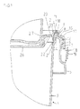
- Fig. 1 shows an injection-molded plastic bucket 1 with snapped lid 2, wherein the outer wall 3 of the Eimers concluding upper edge 4 a flattened area is provided. At the top 4 closes a circumferential and radially outwardly projecting edge 5, to the an outwardly projecting latching edge 6 is formed, the of a circumferential locking edge 7 of the lid with a hook-shaped Projection is under attack.
- the upper edge 4 of the bucket associated with the area of the lid 2 is groove-shaped or channel-shaped, wherein the outer edge 8 of the groove 34 at the two vertically spaced circumferential Ribs 9 of the bucket rests laterally.
- the radial Extension of the ribs 9 is significantly less than the wall thickness of the bucket, here about one third of the same.
- the Ribs 9 are here at the height of the portion 12 of the seal arranged, with the lid even in the absence of these ribs with less or virtually no pretension at this height at the Outer wall of the bucket can rest, which at the same time the Seal is positioned exactly.
- a seal made of an elastic and compressible rubber material integrally molded.
- associated sealing region 12 is arranged at an angle to the vertical, here at an angle of approx. 20 °, whereby the angle also assume values between 5 and 45 ° can, without being limited to.
- the inclined section 12 of the seal 11 is in the snapped condition of the Dekkels at the inside of the bucket top edge 4 subsequent, inwardly sloping slope 13 (see Also Fig. 2,3), whose inclination of the contact surface of the section 12 corresponds to the seal, without being limited thereto to be.
- the lid portion of the section 12 of Seal radially inside surrounds is chamfered executed.
- the outside circumferential edge 5 of the bucket is at the level of Top edge 4 attached, so that the demarcated from the edge 5 Cavity 14 is close to the top edge, d. H. except for about a wall thickness extending.
- the area of the upper edge 4 of the Pail is thus also as a U-shaped circumferential profile designed. As a result, the lid can be optimally braced and laterally occurring forces are absorbed.
- the lid Inboard of the seal 11, the lid has a circumferential Seal web 20 on, the only over a partial area the height sealingly abuts the Eimerinnenwandung, namely in the area of the lower end of the bridge, at about the height of the reinforcing edge 16 and the latching edge is arranged.
- the essentially vertical after Below projecting rib 20 is at the level of an inwardly projecting Paragraph 21 of the bucket inner wall arranged and here slightly vertically spaced therefrom. At lower vertical pressure on the lid sets the rib 20 to paragraph 21.
- the paragraph 21 is turned inwards by a encircling edge 22 limited, instead also individual Projections may be provided, wherein the edge 22 over the Lower edge of the rib 20 protrudes and an inwardly directed Movement of the rib 20 prevents.
- the rib 20 can also be between the edge 22 and the outside adjacent wall portion of the Eimers be recorded in a press fit.
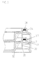
- the rib 20 is slightly inclined outwards so that the sealing area the rib 20, i. the lower end thereof (see Fig. 2) with the cover removed radially outside the container inner wall to come to rest.
- the thickness of the lower edge corresponds here about the rib thickness, preferably more than 1/4 of the same, where it runs slightly conical here. This is at always put on a cover under radial prestress achieved with the container inner wall.
- the area 26 is arranged below the latching edge 6, wherein its outer diameter, as shown, is dimensioned such that a stacking of buckets is possible. This results in projections with triangular cross-section, following a trapezoidal shape are formed below open groove.
- the substantially vertical leg of the U-shaped upper edge 4 goes outwards into a chamfer 15, which a step-shaped paragraph is formed.
- the snap edge 6 is formed, with between snap edge and the paragraph, here at the height of the paragraph, a radially encircling Reinforcement edge 16 is formed, in this Example to the outside at the height of the locking edge 6 concludes and a width corresponding thereto, d. H. vertical extension, having.
- the lower edge of the reinforcing edge 16 is formed according to the latching edge 6, so that the Rastrand 7 of the lid also in the between the edges 6 and 16 arranged groove can intervene, including the upper edge of the latching edge 6 falls obliquely outwards.
- the lid edge is thus in fully snapped on the Outer edge of the latching edge 6 and / or the reinforcing edge 16, whereby together with the sealing web 20 of the upper Tank area is subjected to force on both sides. Especially due to the vertical symmetrical application of force results in a very good tightness. For this also carries the U-shaped configuration of the upper tank area at, the side compressible under a clamping force is. Between bevel 15 and arranged above this Sliding slope 17 of the lid can be a small gap be provided.
- the peripheral edge 5 has below the locking edge 7 a circumferential step shoulder 18, which from the locking edge 7 on protrudes beyond the outer edge of the lid 2, wherein the Retrand 7 sit on the stepped shoulder 18 under tension can or between the curb and step heel also a gap can be provided.
- the stepped shoulder 18 has a tamper-evident closure 19 on, after the removal of the rest of the beach 7 manually grabbed from below and the lid are removed can. It should be noted here that preferably the Cover area between the groove receiving the seal and the catching edge has no significant material weakening, so that between the latching connection and the seal 11 or the inside of the bucket 1 arranged portion of the lid a high stability and thus high tightness given is.
- the outer wall 3 of the bucket has to enable an improved Power transmission with simultaneous stackability of buckets without a lid into each other a conicity or inclination to the outside of less than 3 °, preferably 2 °, wherein even lower inclinations are possible. Furthermore, it is around the forces of stacked buckets with lid in the edge area better able to catch the distance between the bucket center facing side of the wall 25 of the projections and the opposite outer wall of the bucket 27 with only a small Measure game, z. B. with a distance of less than 2 mm, preferably 1 mm.
- the top edge 4 of the bucket edge is two circumferential Ribs 36 provided with the teeth on the Attack underside of the seal 11, and / or next to the ribs 36 in the groove formed between these or outside the same tired of the container edge 4 rest.
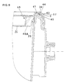
- Fig. 4 is the inside of the bucket wall. 3 arranged circumferential edge 23 of the lid with segments 28, Provided 29 different radial width, resulting in gives an effective stiffening profile to forces on the To catch sealing area of the rib 20 or the seal 11.
- the circumferential extent of the regions 28, 29 amounts to the example a multiple of their width.
- the bevels 24 and vertical wall portions 25 terminate at the same distance from the bucket main axis, wherein the bevel 24 side delimiting areas 29a extend obliquely to the lid circumference.
- the areas 25, 29 and 29a thus limit the projections 25a.
- a lockable Arranged pourer which is about one quarter of the Diameter of the bucket is arranged.
- Fig. 6 shows another embodiment, in which the lid inside projections 49 with substantially vertical Stiffening ribs 46 are provided, which are connected to the outside essentially vertical and essentially horizontal region of the projecting segments 49 connected are and end in front of the circumferential sealing edge 20.
- the stiffening ribs can also up to the sealing edge 20, but preferably not linear abut the sealing edge to seal error due avoiding shrinkage, especially not on Height of the sealing contact area of the sealing rib on the Container interior wall, or with a vertical area, whose vertical extent of the stiffening rib at the level of the inside Edge of the ledge.
- Stiffening ribs 46 may also corresponding to an internal be provided circumferential edge of the lid, the not dissected into protruding and recessed areas.
- the ribs 46 close to the lower edge of the lid portion If necessary, they may also support the lid area 26.
- the sealing ribs 41 exist from the container material and are integrally formed.
- the Container upper edge 40 is here from a radially outer side arranged, circumferential and downwardly projecting web 43 surrounding, which at the radially outwardly projecting circumferential Ribs 9 of the container fits tightly.
- the groove bottom forming horizontal cover portion 44 extends radially outward over the web 43, so that the Abgleitschräge 17th is made steeper than in the previous embodiments. Between web 43 and Abgleitschräge 17 can Stiffening ribs 45 may be provided.
- the Stiffening ribs 46 at the same time the support to the underneath serve lying lid and this line or even punctiform on the top of the internal projections 49th or surrounding edges.
- the sealing rib 20 is in this case spaced from the adjacent lid, If necessary, it can also be supported on it.
- FIG. 8 shows a further embodiment in which the at least one projection 50 at the top of a from the sealing ridge radially inwardly extending and inclined to the container interior sloping portion 51 is formed.
- Area 51 represents here a circumferential edge.
- the projection 50 is executed here web-like, with a variety of webs are integrally formed on the peripheral area.
- the inclined to the container interior sloping portion 51 may also connect directly to the sealing web 20.
- the radially inward flank of the projection can also be inclined run.
- Figure 9 shows a modification of a lid according to the figures 6 and 7 in which the stiffening ribs 46a extend to the Seal web 20 extend and one formed on this Have area whose height is small against the height of the Sealing strip itself.
Abstract
Description
Die Erfindung betrifft einen Kunststoffbehälter mit einrastbarem Deckel und mit am oberen Randbereich des Behälters angeordneter Raste zur rastenden Befestigung des Deckels, wobei der Deckel einen nach unten vorstehenden mit der Behälterinnenseite zur Anlage kommenden umlaufenden Dichtungssteg aufweist, wobei an dem Deckel radial innenliegend zu dem Dichtungssteg mindestens ein Vorsprung vorgesehen ist, der sich im wesentlichen in radialer und im wesentlichen in vertikaler Richtung erstreckt, wobei die vertikale Erstreckung des jeweils an den Dichtungssteg angrenzenden Bereichs des Vorsprungs klein ist gegen die gesamte vertikale Erstreckung des Vorsprungs und/oder gegen die vertikale Erstreckung eines radial innen an den Vorsprung angrenzenden und sich im wesentlichen senkrecht zu diesem erstreckenden Wandbereichs.The invention relates to a plastic container with latchable Cover and arranged at the upper edge region of the container Latch for latching attachment of the lid, wherein the lid a downwardly projecting with the container inside has circumferential sealing web coming to the plant, wherein on the lid radially inwardly of the sealing web at least one projection is provided, located in the essentially in radial and substantially vertical Direction extends, with the vertical extent of each Small area of the projection adjacent the sealing land is against the entire vertical extent of the projection and / or against the vertical extent of a radially inward the projection adjacent and substantially perpendicular to this extending wall area.
Derartige Kunststoffbehälter werden zum Transport verschiedener Güter benutzt, insbesondere auch im industriellen Bereich und im Lebensmittelbereich, und haben sich hierbei vielfach bewährt. Beim Transport von Flüssigkeiten oder niedrig pasteusen Materialien besteht jedoch nach wie vor das Problem einer ausreichenden Dichtigkeit der Kunststoffbehälter. Dies ist insbesondere beim Transport flüchtiger oder aus anderen Gründen kritischer Güter der Fall, wie beispielsweise bei Ölen, insbesondere Mineralölen. In diesen Fällen sind an die Dichtigkeit des Kunststoffbehälters besonders hohe Anforderungen zu stellen, die bei bisher bekannten Kunststoffbehältern nicht zufriedenstellend gelöst werden, auch wenn vielfach versucht wurde, durch geeignete Profilierung des Behälterrandes und des Deckels eine ausreichende Dichtigkeit zu erzielen. Such plastic containers are used to transport different Used goods, especially in the industrial sector and in the food sector, and have many here proven. When transporting liquids or low pastes However, there is still the problem of materials sufficient tightness of the plastic container. This is especially during transport fleeting or for other reasons critical goods, such as oils, especially mineral oils. In these cases are the tightness the plastic container particularly high requirements do not in the known plastic containers be solved satisfactorily, even if tried many times was, by appropriate profiling of the container edge and the Cover to achieve sufficient tightness.
Zur Erhöhung der Steifigkeit der horizontalen Deckelfläche ist es vielfach bekannt, von dem umlaufenden Deckelinnenrand zur Behälterhauptachse, d. h. der durch den Behälterschwerpunkt verlaufenden Behälterlängsachse, hin gerichtete Vorsprünge anzuordnen. Gegebenenfalls sind diese Vorsprünge bzw. ein innenseitig des Behälters umlaufender Deckelrand innseitig mit Versteifungsrippen versehen, die sich an dem innenliegenden Dichtungssteg abstützen. Es hat sich jedoch herausgestellt, daß bei dieser Konstruktion nicht immer eine zuverlässige Dichtigkeit des Behälters erzielt werden kann. Dies gilt insbesondere, wenn für hohe Belastungen die Seitenwände der Vorsprünge bzw. Versteifungsrippen z.B. ring- oder kastenförmiger Vorsprünge eine gewisse Dicke überschreiten.To increase the rigidity of the horizontal lid surface is it is often known, from the encircling lid inner edge to Container main axle, d. H. the through the tank gravity extending container longitudinal axis, directed projections to arrange. Optionally, these projections or a inside of the container surrounding lid edge innseitig with Provided stiffening ribs, which are located on the inside Support the sealing bar. However, it has turned out that not always reliable in this design Tightness of the container can be achieved. This is especially true if for high loads the side walls of the projections or stiffening ribs, e.g. ring-shaped or box-shaped Projections exceed a certain thickness.
Aus der FR 2665 688 ist ein gattungsgemäßer Kunststoffbehälter mit Deckel bekannt, bei dem der obere Randbereich des Behälters unter Ausbildung einer Raste umgebördelt und der Dichtungssteg vertikal beabstandet von der Raste in Verlängerung eines umlaufenden Innenrandes des Deckels angeordnet ist.From FR 2665 688 is a generic plastic container known with lid, in which the upper edge region of the container crimped to form a catch and the sealing web vertically spaced from the detent in extension of a circumferential inner edge of the lid is arranged.
Ferner ist aus der EP 600 127A ein gattungsgemäßer Kunststoffbehälter mit Deckel bekannt, der eine sehr tiefe Aufnahme für den Deckel aufweist, welche an der Füllhöhe der Behälter angepasst ist, wobei in etwa im Randbereich des Deckels ein im wesentlichen horizontaler Kragen vorgesehen ist.Furthermore, from EP 600 127A a generic Plastic container with lid known, which is a very deep Receiving for the lid, which at the level of the Container is adapted, being approximately in the edge region of Lid a substantially horizontal collar is provided.
Der Erfindung liegt die Aufgabe zugrunde, einen Kunststoffbehälter mit einrastbarem Deckel zu schaffen, der bei einer hohen Belastbarkeit den besonderen Anforderungen an die Dichtigkeit genügt.The invention is based on the object, a plastic container to create with latchable lid, which at a high load capacity the special requirements for the tightness enough.
Die Aufgabe wird durch einen Kunststoffbehälter mit einem einrastbaren Deckel gelöst, bei dem der Abdichtungsbereich des Dichtungssteges in etwa auf Höhe des außenliegenden Rastrandes angeordnet ist oder dass an dem Behälter eine außenliegende, umlaufende Versteifungsrippe vorgesehen ist und dass der Abdichtungsbereich des Dichtungssteges in etwa auf Höhe der Versteifungsrippe angeordnet ist. Dem Rastrand des Behälters ist hierbei vorzugsweise ein Rastrand des Deckels zugeordnet, der ohne Materialschwächung in den die Behälteroberkante übergreifenden Deckelbereich übergeht, so dass eine wirksame Kraftübertragung gewährleistet ist. Vorzugsweise ist hierbei der Dichtungssteg nach aussen gestellt, um unter Krafteinwirkung an der Behälterinnenseite anzuliegen, wobei sich die Behälterinnenwandung im Anlagebereich im wesentlichen senkrecht oder leicht nach außen geneigt erstreckt. Hierdurch wird eine besonders hohe Dichtigkeit des Deckels erzielt, da der obere Randbereich des Behälters zumindest annähernd symmetrisch aussenseitig von dem Rastrand des Deckels und innenseitig von dem Dichtungssteg eingezwängt wird, die den Behälterrand in entgegengesetzten Richtungen kraftbeaufschlagen. Der Vorsprung kann hierbei stegförmig oder mit beabstandeten Seitenwänden ausgeführt sein, er kann auch als Versteifungsrippe eines Vorsprunges und/oder eines innenseitig umlaufenden Randes ausgebildet sein. Die Rippe kann als sich vom Deckel nach aussen erstreckende Außenrippe, vorzugsweise als sich vom Deckel zum Behälterinneren hin erstreckende Innenrippe ausgeführt sein. Der sich radial innenliegend anschließende Wandbereich kann z.B. die radial innenliegende Begrenzungswand eines kastenartigen Vorsprunges oder einen innenseitig umlaufenden Rand darstellen. Die vertikale Erstreckung der an den Dichtungssteg angeformten Bereiche kann so z.B. klein sein gegen die Höhe der Vorsprünge bzw. gegen die Höhe der Innen rippen bzw. Seitenwände der dem Behälterinneren zugewandten Seite. Ist somit die Höhe der Innenrippen wesentlich kleiner als die Höhe der Vorsprünge, so können die Innenrippen im wesentlichen eine gleichbleibende Höhe aufweisen. Vorzugsweise entspricht jedoch z.B. die Höhe der Innenrippen auf der der Behälterwand abgewandten Seite derjenigen der Vorsprünge, sodaß die Höhe der Innenrippen radial nach außen abnimmt. Die Gesamthöhe des Vorsprungs entspricht der Höhe des Vorsprungs über die radiale Erstreckung desselben.The task is performed by a plastic container with a latched lid in which the sealing area of the Sealing strip approximately at the level of the outer latching edge is arranged or that on the container an external, circumferential stiffening rib is provided and that the Sealing area of the sealing ridge approximately at height of Stiffening rib is arranged. The latching edge of the container is in this case preferably associated with a latching edge of the lid, without material weakening in the container top edge cross lid area passes, so that ensures an effective power transmission is. Preferably, in this case, the sealing web placed to the outside to force the inside of the container to lie, with the Behälterinnenwandung in the investment area substantially perpendicular or slightly behind extends inclined outside. This will be a particularly high Tightness of the lid achieved because the upper edge of the Container at least approximately symmetrical outside of the Latching edge of the lid and inside of the sealing bar is forced, which the container edge in opposite Apply force to directions. The projection can here be designed web-shaped or with spaced side walls, he can also as a stiffening rib of a projection and / or be formed of an inner circumferential edge. The Rib can be considered as extending from the lid to the outside External rib, preferably as from the lid to Be executed inside the container extending inner rib. The radially inwardly adjoining wall area can e.g. the radially inner boundary wall of a box-like projection or an inner circumferential Represent edge. The vertical extension of the Seal land integrally formed areas may be such. be small against the height of the projections or against the height of the inside ribs or side walls of the container interior facing Page. Is thus the height of the inner ribs much smaller as the height of the protrusions, so can the inner ribs in the essentially have a constant height. Preferably however, it corresponds, e.g. the height of the inner ribs on the Tank wall facing away from that of the projections, so that the height of the inner ribs decreases radially outward. The Total height of the projection corresponds to the height of the projection over the radial extent of the same.
Die vertikale Erstreckung der an den Dichtungssteg angeformten Bereiche der Vorsprünge ist somit auch klein gegen die Höhe des Dichtungssteges, insbesondere gegen dessen sich unterhalb der Anformung erstreckenden Höhe. Die Höhe der Anformung kann weniger als 3/4, z.B. weniger als 1/2 oder weniger als 1/4 der Höhe des Dichtungssteges betragen und z.B. im Bereich der Deckelwandstärke liegen.The vertical extent of the formed on the sealing web Areas of the projections is thus also small against the height the sealing web, in particular against the below the Anformung extending height. The height of the molding can less than 3/4, e.g. less than 1/2 or less than 1/4 of the Height of the sealing web, and e.g. around Cover wall thickness lie.
Dadurch, dass die Höhe der an den Dichtungssteg angeformten bzw. diesem zugewandten Bereiche der Innenrippen bzw. Seitenwände nur vergleichsweise klein ist, lässt sich der Dichtungssteg mit hoher Genauigkeit und Reproduzierbarkeit formen, wobei Material- und/oder Formveränderungen im Bereich des Dichtungssteges, wie z.B. aufgrund von Bindefehlern, Materialschrumpfung und dergleichen auf ein Minimum reduziert werden. Es wurde gefunden, daß Materialspannungen durch die angeformten vertikalen Rippen bzw. Seitenwände sich vertikal über die Anformbereiche hinaus und ggf. bis in den Dichtungsbereich des Steges erstrecken können. Durch die erfindungsgemäße Maßnahme kann der angeformte Vorsprung einen Abstand von dem die höchster Dichtigkeit bewirkenden Bereich des Dichtungssteges beabstandet sein, so daß dieser Dichtungsbereich im wesentlichen frei von Anformungseinflüsse durch den Vorsprung ist. Der Dichtungssteg liegt somit durch die erfindungsgemäße Maßnahmen über den gesamten Umfang auch bei grosser Stärke der Innenrippen bzw. Seitenwände der Vorsprünge sehr gleichmässig an der Behälterinnenwand an, wodurch eine hohe Dichtigkeit des Behälters erreicht wird. Characterized in that the height of the integrally formed on the sealing web or this facing areas of the inner ribs or side walls only comparatively small, can the sealing bar shape with high accuracy and reproducibility, Material and / or shape changes in the field of Sealing web, such as due to binding defects, material shrinkage and the like are reduced to a minimum. It was found that material stresses through the molded vertical ribs or side walls extending vertically over the Beyond molding areas and possibly in the sealing area of the Bridge can extend. By the measure according to the invention the molded projection can be a distance from the highest Tightness causing area of the sealing web spaced be, so that this sealing area substantially is free from Anformungseinflüsse by the projection. Of the Seal web is thus due to the inventive measures over the entire circumference even with great strength of the inner ribs or side walls of the projections very evenly on the Container inner wall, whereby a high density of the container is reached.
Die Höhe der Vorsprünge wie z.B. der Innenrippen bzw. Seitenwände auf der der Behälterwand zugewandten Seite kann weniger als 3/4, z.B. 1/2 oder 1/4 der dem Behälterzentrum zugewandten Höhe bzw. der Gesamthöhe oder der vertikalen Erstreckung des radial innenliegenden und sich im wesentlichen senkrecht zum Vorsprung erstreckenden Wandbereichs betragen. Vorzugsweise schliessen sich die Innenrippen bzw. Seitenwände nur punktförmig an den Dichtungssteg an. Ist der Vorsprung an dem Dichtungssteg unmittelbar angeformt kann der vertikale Abstand der an den Dichtungssteg angrenzenden Unterkante des Vorsprunges von dem Dichtungsbereich des Dichtungssteges (insbesondere dem Bereich größter Dichtungswirkung) 1/4 - 1/2 oder mehr der Höhe des vorsprungs betragen. Der Dichtungsbereich, insbesondere der Bereich größter Dichtungswirkung, kann hierbei auf Höhe des Vorsprungs, z.B. einer Verstärkungsrippe oder einer Seitenwand eines Vorsprungs, liegen, z.B. wenn die Unterkante des Vorsprungs zum Behälterinneren hin abfällt oder der Vorsprung von dem Dichtungssteg beabstandet ist.The height of the protrusions, e.g. the inner ribs or side walls on the side facing the container wall may be less as 3/4, e.g. 1/2 or 1/4 of the tank center facing Height or the total height or the vertical extent of the radially inward and substantially perpendicular to Be projecting extending wall area. Preferably close the inner ribs or side walls only punctiform to the sealing bar on. Is the projection on the sealing web directly formed, the vertical distance of at the sealing ridge adjacent lower edge of the projection from the sealing region of the sealing web (in particular the Area of greatest sealing effect) 1/4 - 1/2 or more of the height of the projection amount. The sealing area, in particular the area of greatest sealing effect, this can be at height of the projection, e.g. a reinforcing rib or sidewall of a projection, e.g. if the lower edge of the Projection towards the container interior down or the projection is spaced from the sealing web.
Nach einer besonders bevorzugten Ausführungsform ist der mindestens eine Vorsprung bzw. die Seitenwände oder Innenrippen desselben von dem behälterinnenseitig angeordneten Dichtungssteg radial beabstandet, so dass sich aufgrund von nicht gleichmässig über den Umfang des Behälters verteilten Materialansammlungen entstehende Materialspannungen nicht unmittelbar auf den Dichtungssteg übertragen. Liegen somit z.B. ringförmige bzw. kastenförmige wie z.B. quader- oder prismenförmige Vorsprünge vor, so sind die Seitenwände bzw. Innenrippen der Vorsprünge nur an ihren oberen und radial innenliegenden Seiten mit dem Deckel verbunden. Es wurde festgestellt, dass hierdurch eine ausreichende Stabilität der Vorsprünge ohne störenden Einfluss auf den Dichtungssteg erzielt werden kann. Die Innenrippen können ggf. auch den inneren im wesentlichen horizontalen Deckelbereich unterstützen und an der Deckelunterseite angeformt sein.According to a particularly preferred embodiment, the at least a projection or the side walls or inner ribs the same of the container inside arranged sealing web radially spaced, so that due to not uniformly distributed over the circumference of the container material accumulations resulting material stresses not immediate transferred to the sealing web. Thus, for example, if annular or box-shaped such as e.g. cuboid or prismatic Projections before, so are the side walls or inner ribs the projections only at their upper and radially inner Pages connected to the lid. It was found that This provides sufficient stability of the projections without disturbing influence on the sealing web can be achieved. The inner ribs may possibly also the inner substantially support horizontal lid area and on the underside of the lid be formed.
Der Dichtungssteg kann einen linienförmigen oder flächigen Anlagebereich mit der Behälterinnenwand aufweisen. Der abdichtende Anlagebereich des im Querschnitt vorzugsweise länglichen Dichtungssteges ist hierbei vorzugsweise unterhalb der an dem Dichtungssteg angeformten Bereiche des Deckels wie z.B. der Innenrippen bzw. Seitenwände der Vorsprünge vorgesehen, besonders bevorzugt im Bereich oder am unteren freien Ende des Dichtungssteges. Hierdurch kann der Anlagebereich eine gewisse Flexibilität aufweisen, was oftmals nicht mehr in ausreichendem Ausmass gegeben ist, wenn z.B. die Deckelinnenfläche oder die Vorsprünge mit ihrer Oberseite an dem unteren Bereich des Dichtungssteges angeformt sind, wodurch die Flexibilität des Dichtungssteges beeinträchtigt und zudem z.B. bei einer Stapelung von Behältern von den Vorsprüngen aufgenommene Kräfte auf den unteren Bereich des Dichtungssteges übertragen werden würden, wodurch dessen Dichtungsfunktion beeinträchtigt werden kann. Der abdichtend an die Behälterinnenwand anlegende Anlagebereich kann sich über ein Vielfaches der Deckelwandstärke, z.B. in etwa das 4-fache derselben erstrecken, ohne hierauf beschränkt zu sein.The sealing bar can be a linear or flat Have investment area with the container inner wall. The sealing Investment region of the cross-section preferably elongated Seal web is here preferably below the on the Seal web molded areas of the lid such. of the Interior ribs or side walls of the projections provided, especially preferably in the region or at the lower free end of the Sealing web. As a result, the investment area a certain Have flexibility, which is often not sufficient Extent is given when, for. the lid inner surface or the projections with their top on the lower portion of the Seal webs are formed, whereby the flexibility of the Dichtungssteges impaired and also, for. in a stacking from containers absorbed by the projections forces be transferred to the lower portion of the sealing web would, whereby its sealing function are impaired can. The abdichtend to the container inner wall applying investment area can exceed a multiple of the top wall thickness, e.g. extend about 4 times the same, without it to be limited.
Der Dichtungssteg erstreckt sich vorteilhafterweise ausgehend von den angeformten und sich radial einwärts zum Deckelinneren hin erstreckenden Deckelbereichen über eine vertikale Höhe, die einem vielfachen der Deckelwandstärke entspricht, vorzugsweise der 2- bis 5-fachen Deckelwandstärke oder darüber hinaus. Vorzugsweise ist der Dichtungssteg über diese Höhe frei von sich radial erstreckenden Anformungen. Die Wandstärke des Dichtungssteges kann im Bereich von 0,5 bis 1,5 der Deckelwandstärke betragen, z.B. in etwa dieser entsprechen.The sealing web advantageously extends starting from the molded and radially inward to the lid interior extending lid areas over a vertical height, which corresponds to a multiple of the top wall thickness, preferably 2 to 5 times the top wall thickness or beyond. Preferably, the sealing web is free over this height of radially extending projections. The wall thickness of the Seal web can be in the range of 0.5 to 1.5 of the top wall thickness amount, e.g. roughly correspond to this.
Der Abdichtbereich des Dichtungssteges, beispielsweise das untere Ende desselben, liegt vorzugsweise im Bereich der vertikalen Höhe der Deckelvorsprünge, beispielsweise im Bereich der halben Höhe oder des unteren Drittels der Vorsprünge.The sealing region of the sealing web, for example the lower end thereof, is preferably in the range of vertical Height of the lid projections, for example in the area half the height or the lower third of the projections.
Der Querschnitt der Vorsprünge kann z.B. drei- oder viereckig ausgeführt sein,ggf. auch schiefwinklig, wobei die Ober- und/oder Unterkante der Seitenwände der Vorsprünge bzw. der Innenrippen zum Behälterinneren abfallen (vorzugsweise mit einer Neigung von < 15°, z.B. ca. 5°) oder horizontal verlaufen. Die radial innenliegende Stirnwand der Vorsprünge bzw. Innenrippen kann vertikal oder geneigt verlaufen.The cross section of the projections may e.g. triangular or quadrangular be executed, if necessary also obliquely, whereby the upper and / or lower edge of the side walls of the projections or the Inner ribs fall to the interior of the container (preferably with an inclination of <15 °, e.g. approx. 5 °) or horizontally. The radially inner end wall of the projections or Internal ribs can be vertical or inclined.
Nach einer vorteilhaften Ausführungsform kann der mindestens eine Vorsprung an der Oberseite eines sich von dem Dichtungssteg radial einwärts erstreckenden und geneigt zum Behälterinneren abfallenden Bereichs angeformt sein. Der Vorsprung kann hierbei steg- oder kastenförmig ausgeführt sein.According to an advantageous embodiment, the at least a protrusion on the top of one of the sealing web radially inwardly extending and inclined to the container interior sloping region be formed. The lead can be designed web or box-shaped.
Vorzugsweise ist an dem Dichtungssteg innenseitig ein umlaufender Rand angeformt, an dem radial nach innen die zum Behälterinneren vorspringenden Vorsprünge angeformten sind. Der Rand kann zum Behälterinneren hin nach unten geneigt oder im wesentlichen horizontal verlaufen, ohne hierauf beschränkt zu sein. Vorzugsweise erstreckt sich der umlaufende Rand in radialer Richtung über eine oder mehrere Wandstärken desselben, z.B. über ca. 2 - 3 Wandstärken ausgehend von der Innenseite des Dichtungssteges. Bei Betrachtung des Deckels von der Unterseite her ergibt sich somit eine umlaufende Nut mit z.B. annähernd trapezförmigem oder dreieckigem Querschnitt und nach innen gerichteten Verbreiterungen. Die Innenrippen bzw. Seitenwände der Vorsprünge sind somit in radialer Richtung von dem Dichtungssteg bzw. dem oberen Deckelrand beabstandet. Hierduch wird eine hohe Steifigkeit des Deckelinneren, z.B. zur Stapelung von Behältern, bei hoher Dichtigkeit des Behälters erzielt.Preferably, on the sealing web inside a circumferential Formed edge, at the radially inward to the container interior protruding projections are formed. Of the Edge can be tilted down to the inside of the container or in the essentially horizontally, but not limited thereto be. Preferably, the peripheral edge extends in radial Direction over one or more wall thicknesses of the same, e.g. about 2 - 3 wall thicknesses starting from the inside of the sealing bar. Looking at the lid from the bottom This results in a circumferential groove with e.g. approximately trapezoidal or triangular in cross-section and after inside widening. The inner ribs or side walls the projections are thus in the radial direction of the sealing web or the upper lid edge spaced. Thereby, a high rigidity of the lid interior, e.g. for stacking containers, with high density of the container achieved.
Die inneren versteifungsrippen können sowohl bei mehreren separaten Vorsprüngen wie z.B. im wesentlichen kastenförmigen Vorsprüngen als auch bei einem ringförmig umlaufenden Vorsprung, der einen rinnenförmigen Deckelrand bildet, vorgesehen sein.The inner stiffening ribs can be used both at several separate protrusions such as e.g. essentially box-shaped Projections as well as in an annular circumferential projection, which forms a channel-shaped lid edge be.
Die Vorsprünge können an der Oberkante des Deckels angeformt sein. Vorteilhafterweise ist die Oberseite der Vorsprünge beabstandet von bzw. unterhalb des Abdichtbereichs der Deckeloberkante angesetzt, so dass ein weiterer Stufenabsatz entsteht. Eine Anformung auf Höhe des Dichtbereichs der Behälterinnenseite, die zu Materialspannungen bzw. Formänderungen z.B. aufgrund von Schrumpfungsvorgängen führen können, werden hierdurch vermieden. Erstreckt sich der Abdichtbereich an der Behälteroberkante über einen vertikalen Bereich, so kann die Oberseite der Vorsprünge auch in etwa auf Höhe des unteren Endes des Abdichtbereichs angeordnet sein. Dies gilt sowohl dann, wenn der Abdichtbereich nur durch unmittelbare Anlageflächen von Deckel und Eimer erzeigt werden, als auch wenn eine flexible Dichtung vorgesehen ist.The projections can be formed on the upper edge of the lid be. Advantageously, the top of the projections spaced from or below the sealing area of the lid top edge set, so that a further step sales arises. An Anformung at the height of the sealing area of the container inside, resulting in material stresses or shape changes, e.g. due to shrinking operations, thereby become avoided. The sealing area extends at the Container top edge over a vertical area, so can the Top of the projections also at about the level of the lower Be arranged end of the sealing region. This is true then, if the sealing area only by direct contact surfaces be produced by the lid and bucket, as well a flexible seal is provided.
Vorzugsweise ist bei aufgesetztem Deckel unmittelbar unterhalb des Dichtungssteges ein Absatz in der Behälterwandung eingeformt. Der Dichtungssteg kann bei aufgesetztem Deckel auf dem Absatz aufsitzen, aber auch von diesem derart beabstandet sein, dass bei aufgestapelten weiteren Behältern oder bei äusserer Kraftausübung die Unterseite des Steges sich an dem Behälterabsatz abstützt. Der Stufenabsatz der Behälterinnenwand, der unterhalb des Dichtungssteges des Deckels angeordnet ist, kann in etwa auf Höhe der Raste oder einer Verstärkungsrippe angeordnet sein bzw. im Abstand einer oder einiger weniger Behälterwandstärken.Preferably, with the lid on immediately below formed a paragraph in the container wall of the sealing web. The sealing bar can with the lid on the Sitting on paragraph, but also so spaced from this be that when piled on other containers or at external force exerting the bottom of the bridge on the Container paragraph supports. The stepped shoulder of the container inner wall, which is arranged below the sealing web of the lid can be roughly at the height of the catch or a reinforcing rib be arranged or at a distance of one or a few Container wall thicknesses.
Um die Zuverlässigkeit des Behälterverschlusses zu erhöhen, kann an der Behälterinnenwand radial innenliegend zu dem umlaufenden Dichtungssteg ein bis über die Unterkante desselben nach oben vorstehender Bereich vorgesehen sein. Dieser Bereich ist vorzugsweise an dem innenliegenden Behälterabsatz angeformt. Hierzu können einzelne über den Umfang verteilte Vorsprünge oder Stege vorgesehen sein, vorzugsweise ist dieser Bereich ebenfalls als umlaufende Rippe ausgebildet. Die Höhe dieser Rippe, die eine Einwärtsverschiebung des Dichtungssteges des Deckels verhindert, ist vorzugsweise kleiner als die Wandstärke des Behälters bzw. des Dichtungssteges, ohne hierauf beschränkt zu sein. Die nach oben vorstehenden Bereiche des Behälters können geringfügig beabstandet oder mit oder ohne Vorspannung seitlich an dem Dichtungssteg des Deckels anliegen. Der Dichtungssteg des Deckels kann hierbei auch im Presssitz zwischen den radial innen und aussen angrenzenden Behälterbereichen anordnenbar sein.To increase the reliability of the container closure, can at the container inner wall radially inward to the circumferential Seal web on to over the lower edge of the same be provided upwardly projecting area. This area is preferably formed on the inner container paragraph. For this purpose, individual distributed over the circumference projections or webs may be provided, preferably this is Area also formed as a circumferential rib. The height this rib, which is an inward displacement of the sealing bar prevents the lid is preferably smaller than the wall thickness of the container or of the sealing web, without to be limited to this. The upwardly projecting areas of the container may be slightly spaced or with or without bias on the side of the sealing web of the lid issue. The sealing web of the lid can also be in Press fit between the radially inside and outside adjacent Be arranged container areas.
Vorzugsweise ist im Bereich der Behälteroberkante ein weiterer Abdichtbereich zwischen Behälter und Deckel angeordnet. Der Abdichtbereich kann eine Dichtung aus einem Material höherer Elastizität als der des Deckels und des Eimers aufweisen, insbesondere aus einem Gummimaterial. Die Dichtung kann einstückig an einem der Teile angeformt sein, wodurch Lagetoleranzen vermieden und auch bei Krafteinwirkung, z.B. bei herabfallenden Behältern, die Dichtung stets unverrückbar an dem Bauteil angeordnet ist. Die Dichtung ist vorzugsweise durch ein Spritzverfahren, z.B. im Spritzguss, angeformt, so dass Klebestellen oder dergleichen vermieden werden. Die Dichtung kann auch nur kraft- und/oder formschlüssig gehaltert, z.B. in eine Ringnut eingelegt sein. Der Abdichtbereich im Bereich der Behälteroberkante kann auch unmittelbar durch Anlagebereiche von Deckel und Eimer ausgebildet sein.Preferably, in the region of the upper edge of the container another Sealing arranged between the container and lid. Of the Sealing area can be a seal made of a material higher Have elasticity than that of the lid and bucket, in particular from a rubber material. The seal can be one piece be formed on one of the parts, whereby positional tolerances avoided and also when force, for. in falling Containers, the seal always immovable to the Component is arranged. The seal is preferably through a spraying method, e.g. in injection molding, molded, so that Gluing or the like can be avoided. The seal can also be held only non-positively and / or positively, for. in be inserted an annular groove. The sealing area in the area of Container top edge can also directly through investment areas be formed by the lid and bucket.
Vorteilhafterweise ist die Dichtung am Deckel angeformt, wobei die Breite der Dichtung grösser als die Wandstärke des oberen Behälterrandes bemessen sein kann. Die Dichtung kann einen im wesentlichen horizontal verlaufenden Abdichtbereich aufweisen, es können ein, zwei oder mehrere unterschiedliche Dichtbereiche vorgesehen sein, die sich bezüglich ihrer Anlagebreite, Materialstärke oder anderer Eigenschaften unterscheiden können. Die Dichtbereiche können jeweils ineinander übergehen oder voneinander radial oder axial beabstandet sein.Advantageously, the seal is integrally formed on the lid, wherein the width of the seal is greater than the wall thickness of the upper one Container edge can be measured. The seal may have an im have substantially horizontally extending sealing area, There may be one, two or more different sealing areas be provided, which in terms of their investment width, Material thickness or other properties can differ. The sealing areas can merge into each other or spaced apart radially or axially.
Die Dichtung weist vorzugsweise zwei benachbarte Dichtbereiche auf, die eine unterschiedliche Neigung aufweisen und an Bereichen des Behälterrandes mit unterschiedlicher Neigung abdichtend anlegbar sind. Die Dichtung kann hierzu insbesondere einen U-, V- oder L-förmigen Querschnitt oder andere Profilierungen aufweisen, wobei die Dichtbereiche an aufeinander zuweisenden Bereichen der Dichtung angeordnet sein können, ggf. aber auch z.B. an einem konvexen Bereich. The seal preferably has two adjacent sealing areas on, which have a different inclination and areas the container edge with different inclination sealing can be applied. The seal can this particular a U, V or L-shaped cross section or other profiles have, wherein the sealing areas on facing each other Regions of the seal can be arranged, if necessary but also e.g. at a convex area.
Vorteilhafterweise ist die Dichtung in einer umlaufenden, den Behälterrand umgebenden Nut des Deckels angeordnet, wobei sich die Dichtung über die gesamte Breite der Nut erstrecken kann und hierdurch gegen seitliche Verschiebung zusätzlich gesichert ist. Der behälterseitig innenliegende Dichtungssteg kann als Verlängerung des inneren Schenkels der Nut ausgebildet sein.Advantageously, the seal in a circumferential, the Container edge surrounding groove of the lid arranged, wherein the seal can extend over the entire width of the groove and thereby additionally secured against lateral displacement is. The container-side inner sealing web can formed as an extension of the inner leg of the groove be.
Vorzugsweise weist die Dichtung im verschlossenen Zustand des Behälters einen im wesentlichen horizontalen Bereich auf, der abdichtend an der Oberkante des Behälterrandes anlegbar ist, und einen radial innenliegenden Bereich, der vorzugsweise abwärts geneigt ist und an die Innenseite des oberen Behälterrandes dichtend anlegbar ist. Der abwärts geneigte Dichtungsbereich kann sich bei aufgestelltem Behälter im wesentlichen vertikal oder schräg geneigt erstrecken, wobei die beiden Dichtungsbereiche einen Winkel von 90°-135° oder mehr einschliessen können. Vorzugsweise weist der Behälterrand ebenfalls einen horizontalen Abdichtbereich und eine radial innenliegende Abschrägung bzw. Fase zur Anlage des vertikal bzw. schräg angeordneten Dichtungsbereich auf. Hierdurch werden auch bei seitlicher Krafteinwirkung auf den Dichtungsbereich Kräfte stets im Bereich der flexiblen Dichtung aufgefangen, so dass eine Auslaufsicherheit in hohem Masse gegeben ist.Preferably, the seal in the closed state of Container on a substantially horizontal area, the sealingly on the upper edge of the container edge can be applied, and a radially inner region, preferably is inclined downwards and to the inside of the upper container edge is sealingly applied. The downward sloping sealing area can essentially stand in a container extend vertically or obliquely, the two Sealing areas an angle of 90 ° -135 ° or more include can. Preferably, the container rim also a horizontal sealing area and a radially inside Bevel or chamfer to create the vertical or obliquely arranged sealing area. This will be also with lateral force on the sealing area Forces always caught in the field of flexible gasket, so that leakage safety is given to a high degree.
Die Dichtung kann eine oder mehrere zum Behälterrand vorstehende umlaufende Dichtungsstege aufweisen, die zur Anlage mit einem Behälterbereich, insbesondere der Behälteroberkante, kommen. Der Behälterrand kann eben oder mit einer oder mehreren umlaufenden Rippen versehen sein, die paarweise eine Nut ausbilden können, in die eine oder mehrere Dichtungsstege zumindest teilweise eingreifen. Die miteinander zur Anlage kommenden Strukturierungen von Dichtung und Behälterrand können auch unkompatibel sein, so dass Erhebungen der Dichtung nicht Vertiefungen des Behälterrandes gegenüberliegen sondern mit Erhebungen des Behälterrandes zur Anlage kommen, z.B. im Flankenbereich derselben. Hieraus resultiert eine nichtkongruente Verzahnung, die eine hohe und zuverlässige Dichtigkeit gewährleistet. Die Höhe der Dichtungsstege ist hierbei vorzugsweise kleiner als die Behälterwandstärke, z.B. die 1/2 bis 1/5 derselben oder kleiner, ohne hierauf beschränkt zu sein.The seal may be one or more protruding from the container rim have circumferential sealing webs, which are to invest with a container area, in particular the upper edge of the container, come. The container rim may be flat or with one or more circumferential ribs are provided, which in pairs a groove can form into the one or more sealing webs at least partially intervene. The to each other to the plant upcoming structuring of seal and container edge can also be incompatible, so that surveys of the seal not opposite depressions of the container edge but come to bumps with the container edge, for. in the Flank area of the same. This results in a non-congruent Gearing, which has a high and reliable tightness guaranteed. The height of the sealing webs is in this case preferably smaller than the container wall thickness, e.g. the 1/2 to 1/5 of the same or less, without being limited thereto.
Die obigen Ausführungen in der Geometrie der Dichtung, der Ausbildung von Dichtungsstegen usw. gelten entsprechend auch für einen an Deckel und Behälter angeformten Dichtungsbereich, bei dem also Bereiche des Deckels und Behälters unmittelbar miteinander zur Anlage kommen.The above statements in the geometry of the seal, the Training of sealing bars, etc. apply accordingly for a sealing area formed on the lid and container, in which so areas of the lid and container immediately to come together.
An dem der Behälteroberkante benachbarten und nach aussen abfallenden Bereich der Behälteraussenwand können radial nach aussen vorspringende Stege angeformt sein, die als umlaufende Rippen ausgeführt sein können, deren radiale Erstreckung kleiner ist als die Behälterwandstärke. Diese Rippen können aus dem gleichen Material bestehen wie die Behälterwandung und dienen im wesentlichen dazu, die Reibung beim Aufsetzen des Deckels zu verringern, wobei sie nur eine untergeordnete Dichtungsfunktion haben. Es können auch zwei oder mehr vertikal beabstandete umlaufende Rippen angebracht sein. Die Rippen liegen bei aufgesetztem Deckel vorzugsweise spielfrei aber ohne nennenswerte Vorspannung an, wodurch der Deckel im Abdichtungsbereich der Behälteroberkante exakt positioniert wird, oder sind mit geringem Spiel beabstandet, ohne hierauf beschränkt zu sein.At the upper edge of the container adjacent and falling outwards Area of the container outer wall can radially to externally projecting webs to be formed, as the circulating Ridges can be designed whose radial extent smaller is as the tank wall thickness. These ribs can be out the same material as the container wall and serve essentially to the friction when placing the Cover, with only a minor sealing function to have. It can also be two or more vertical be spaced circumferential ribs attached. Ribs lie with attached lid preferably free of play but without appreciable bias, causing the lid in the sealing area the container top edge positioned exactly is, or are spaced with little play, without it to be limited.
Zur Stabilisierung des Dichtungsbereiches ist, vorzugsweise aussenseitig, an dem Behälterrand auf der der Behälteroberkante zugewandten und/oder abgewandten Seite der Raste eine oder mehrere radial vorstehende Verstärkungsrippe(n) angeformt. Die Verstärkungsrippe läuft vorzugsweise radial um den Behälter um, sie kann auch unterteilt sein und aus mehreren Verstärkungsbereichen bestehen. Es können auch auf der der Behälteroberkante zugewandten und der abgewandten Seite der Raste je eine oder mehrere verstärkungsrippen angeformt sein. Die Stärke, d.h. Höhe und/oder Breite der verstärkungsrippe kann im Bereich der wandstärke des Behälters oder darüber liegen. Durch die Anordnung der Verstärkungsrippe benachbart der flexiblen Dichtung ist der Abdichtbereich im Bereich der Behälteroberkante besonders stabilisiert. Vorzugsweise liegt der Deckel an der radial aussenliegenden Seite der Verstärkungsrippe mit oder ohne Vorspannung an, wodurch seitlich auf den Deckel einwirkende Kräfte unmittelbar von der Verstärkungsrippe aufgenommen werden. Die radiale Aussenseite der Verstärkungsrippe kann hierzu einen ebenen Bereich aufweisen. Der Abstand zwischen Verstärkungsrippe und Raste oder zwischen diesen kann zur Einrastung des Rastrandes des Deckels ausgelegt sein. Sind die Verstärkungsrippen unmittelbar an der Behälterwand angeordnet, so werden auch durch den inneren Dichtungssteg auf die Behälterwand ausgeübte Kräfte aufgefangen. Entsprechendes gilt für den Rastrand bei einer ausreichenden Steifigkeit desselben.To stabilize the sealing area is, preferably on the outside, at the container edge on the upper edge of the container facing and / or opposite side of the catch one or a plurality of radially projecting reinforcing rib (s) formed. The Reinforcing rib preferably passes radially around the container around, it can also be subdivided and made up of several amplification areas consist. It can also be on the top of the container facing and the opposite side of the latch depending one or more reinforcing ribs be formed. The strenght, i.e. Height and / or width of the rib can be in Range of wall thickness of the container or above. By the arrangement of the reinforcing rib adjacent to the flexible Seal is the sealing area in the area of the upper edge of the container especially stabilized. Preferably, the Cover on the radially outer side of the reinforcing rib with or without preload, which makes it laterally on the Lid acting forces directly from the reinforcing rib be recorded. The radial outside of the reinforcing rib can have a flat area for this purpose. Of the Distance between reinforcing rib and notch or between this can be designed for locking the latching edge of the lid be. Are the reinforcing ribs directly on the Container wall arranged, so are also by the inner Gasket collected on the vessel wall forces absorbed. The same applies to the latching beach with a sufficient Stiffness of the same.
Die Rastung des Deckels ist vorteilhafterweise auch nach einmaliger Öffnung des Behälters unverändert wirksam, d.h. Rastbereich und Dichtungsbereich sind nicht durch eine Materialschwächung unterbrochen, die als Originalitätsverschluss dient oder bei welcher der Deckelbereich teilweise oder vollständig zur Öffnung des Behälters zu entfernen bzw. umzuklappen ist.The detent of the lid is advantageously even after one-time Opening of the container unchanged effective, i. Rest area and sealing area are not due to a material weakening interrupted, which serves as a tamper-evident closure or in which the lid portion partially or completely is to remove or fold over the opening of the container.
Vorzugsweise ist die die Behälteröffnung abdeckende Deckelinnenfläche, die als Stapelfläche für Behälter dienen kann, in etwa auf der Höhe oder unterhalb der Unterkante des behälterinnenseitigen Dichtungssteges angeordnet. Hierdurch kann die Deckelinnenfläche bei Krafteinwirkung auf diese, z.B. bei einer Stapelung von Behältern, kräftemässig von dem Dichtungssteg weitestgehend abgekoppelt werden.Preferably, the cover opening surface covering the container opening, which can serve as a stacking area for containers, in approximately at the level or below the lower edge of the container inside Seal arranged. This allows the Cover inner surface upon application of force thereto, e.g. at a stack of containers, in terms of strength of the sealing web be decoupled as far as possible.
Des weiteren ist vorzugsweise die Deckelinnenfläche in etwa auf der Höhe oder unterhalb des aussenliegenden Rastrandes bzw. einer radial vorstehenden Verstärkungsrippe angeordnet. Da der Deckel aussenseitig ebenfalls von dem Rastrand bzw. von der Verstärkungsrippe abgestützt wird, ergibt sich bei seitlicher aber insbesondere bei vertikaler Kraftausübung auf den Deckel eine gleichmässige Kraftverteilung und damit höhere Zuverlässigkeit bezüglich der Dichtigkeit des Behälters. Furthermore, preferably the lid inner surface is approximately at the level or below the outer beach or a radially projecting reinforcing rib arranged. Since the lid also on the outside of the locking edge or of the reinforcing rib is supported, results in lateral but especially with vertical exercise of force on the Cover a uniform force distribution and thus higher Reliability regarding the tightness of the container.
Der innenseitige obere Behälterrand kann mit einem abgeschrägten Bereich versehen sein, der der erleichterten Einführung des Dichtungssteges dient und auch auch als Dichtungsbereich ausgebildet sein kann, z.B. zur Anlage einer flexiblen Dichtung oder unmittelbar eines Dichtungsbereichs des Deckels. Der Winkel zwischen der abgeschrägten Oberkante und der Vertikalen ist spitzwinklig ausgeführt, d.h. beträgt weniger als 45°.The inside upper container edge can be with a bevelled Be provided with the area of facilitated introduction the sealing bar serves and also as a sealing area may be formed, e.g. to create a flexible seal or immediately a sealing portion of the lid. Of the Angle between the bevelled top edge and the vertical is executed at an acute angle, i. is less than 45 °.
Der Deckel aknn eine nach aussen weisende Abgleitschräge aufweisen, die sich an die Oberkante des Deckels oder an einen darunterliegenden Bereich desselben anschliessen kann. Die Abgleitschräge kann radial nach aussen mit dem Rast-rand des Deckels abschliessen oder über diesen hinausragen, vorzugsweise erstreckt sie sich radial bis über von der Behälterwand nach aussen vorspringende Bereiche hinaus.The cover aknn have an outwardly facing Abgleitschräge, to the top of the lid or to a can connect the underlying area of the same. The Sliding slope can be radially outward with the locking edge of the Close or overhang lids, preferably it extends radially to over from the container wall outward protruding areas.
Der obere Rand des Behälters weist vorzugsweise einen radial nach aussen vorstehenden, nach unten gezogenen umlaufenden Randbereich auf, an dem die Raste angeformt ist. Eine oberhalb der Raste angeformte, nach aussen weisende Verstärkungsrippe kann hierbei ebenfalls an dem umlaufenden Behälterrand angeformt sein, wodurch dieser ebenfalls verstärkt wird, und/oder oberhalb des umlaufenden Randbereichs unmittelbar an der Behälterwandung. Durch den nach unten gezogenen, von der Behälterwand beabstandeten Randbereich wird der Rastbereich kräftemässig von dem Dichtbereich des Dichtungssteges an der Behälterinnenseite und an der Behälteroberkante entkoppelt.The upper edge of the container preferably has a radial outwardly projecting, pulled down circumferential Edge area on which the catch is formed. One above the catch molded, outwardly facing reinforcing rib can also be formed on the peripheral edge of the container be, whereby this is also reinforced, and / or above the peripheral edge region directly on the container wall. By the drawn down, from the container wall spaced edge area of the locking area is based on power from the sealing area of the sealing web on the inside of the container and decoupled at the upper edge of the container.
Vorzugsweise ist der nach unten gezogene umlaufende Randbereich an der Oberkante des Behälters angesetzt, d.h. auf Höhe des Dichtbereichs oder in einem Abstand von wenigen Wandstärken, z.B. ein oder zwei, ohne hierauf beschränkt zu sein.Preferably, the downwardly drawn peripheral edge region attached to the upper edge of the container, i. at height the sealing area or at a distance of a few wall thicknesses, e.g. one or two, without being limited thereto.
Der Behälter weist vorzugsweise einen radial nach aussen vorstehenden, nach unten gezogenen Randbereich auf, der unterhalb des auf den Behälter aufgesetzten Deckels angeordnet ist und sich radial bis zum Deckel oder auch darüber hinaus erstreckt. Dieser umlaufende Randbereich kann separat an der Behälterwand angeformt sein und hierbei mit der Unterkante des den Rastrand aufweisenden umlaufenden Randbereichs abschliessen oder von diesem in der Höhe beabstandet sein. Vorzugsweise ist dieser umlaufende Randbereich als Fortsetzung des die Rastung aufweisenden Randbereichs ausgebildet, d.h. als nach unten und nach aussen fortgesetzter Absatz. Die Deckelunterkante kann mit oder ohne Vorspannung auf diesem Randbereich aufsitzen oder ein geringes Spiel zu diesem aufweisen wozu eine radiale Einschnürung zur teilweisen oder vollständigen Aufnahme der Deckelunterkante vorgesehen sein kann.The container preferably has a radially outwardly projecting, pulled down edge area, the below of the lid placed on the container is arranged and extends radially to the lid or beyond. This peripheral edge area can be attached separately to the container wall be molded and this with the lower edge of the locking edge conclude having circumferential edge region or from this be spaced in height. Preferably, this is circumferential edge region as a continuation of the detent having Edge region formed, i. as down and outward continued paragraph. The lower lid edge can sit with or without preload on this edge area or have a slight play to this what a radial Constriction for partial or complete uptake of Cover lower edge can be provided.
Die die Behälteröffnung versperrende Deckelfläche kann auf Höhe oder unterhalb des innenliegenden Dichtungsbereichs, vorzugsweise auf Höhe oder unterhalb des Rastrandes angeordnet sein.The lid opening obstructing the container opening can open Height or below the inner sealing area, preferably arranged at height or below the latching edge be.
An dem Deckel kann eine Ausgusstülle angebracht sein, die vorzugsweise ca. auf ein Viertel des Durchmessers der Deckelfläche angeordnet ist, wodurch sich eine praktische Handhabung des Eimers beim Ausgiessen einer Flüssigkeit ergibt.On the lid, a spout may be attached, the preferably about one quarter of the diameter of the lid surface is arranged, resulting in a practical handling of the bucket when pouring a liquid results.
Die Erfindung sei nachfolgend beispielhaft beschrieben und anhand der Figuren beispielhaft erläutert. Es zeigen:
- Fig. 1
- eine Teilansicht eines erfindungsgemässen Behälters mit Deckel und gestapeltem weiteren Behälter in Schnittdarstellung,
- Fig. 2
- eine Detailansicht eines Behälters mit Deckel nach Fig. 1,
- Fig. 3
- eine Detailansicht eines Behälters nach Fig. 1 in Schnittdarstellung.
- Fig. 4
- eine Draufsicht auf einen Behälter mit Deckel nach Fig. 1,
- Fig. 5
- ein Stapelschema von Deckeln nach Fig. 1,
- Fig. 6
- eine Detailansicht eines Behälters mit Deckel nach einer weiteren Ausführungsform,
- Fig. 7
- ein Stapelschema von Deckeln nach Fig. 6,
- Fig. 8
- eine Detailansicht eines Deckels nach einer weiteren Ausführungsform,
- Fig. 9
- eine Detailansicht eines Deckel nach einer Abwandlung des Deckels nach Figur 6.
- Fig. 1
- a partial view of an inventive container with lid and stacked further container in section,
- Fig. 2
- a detailed view of a container with lid of Fig. 1,
- Fig. 3
- a detailed view of a container of FIG. 1 in a sectional view.
- Fig. 4
- a top view of a container with lid of Fig. 1,
- Fig. 5
- a stacking scheme of lids according to Fig. 1,
- Fig. 6
- a detailed view of a container with lid according to a further embodiment,
- Fig. 7
- a stacking scheme of lids according to Fig. 6,
- Fig. 8
- a detailed view of a lid according to a further embodiment,
- Fig. 9
- a detailed view of a lid according to a modification of the lid of Figure 6.
Fig. 1 zeigt einen spritzgegossenen Kunststoffeimer 1 mit
aufgerastetem Deckel 2, wobei an der die Aussenwand 3 des
Eimers abschliessenden Oberkante 4 ein abgeflachter Bereich
vorgesehen ist. An der Oberkante 4 schliesst sich ein umlaufender
und radial nach aussen vorstehender Rand 5 an, an den
ein nach aussen vorstehender Rastrand 6 angeformt ist, der von
einem umlaufenden Rastrand 7 des Deckels mit einem hakenförmigen
Vorsprung untergriffen wird.Fig. 1 shows an injection-molded plastic bucket 1 with
snapped
Der der Oberkante 4 des Eimers zugeordnete Bereich des Deckels
2 ist nut- bzw. rinnenförmig ausgebildet, wobei die Aussenflanke
8 der Nut 34 an den beiden vertikal beabstandeten umlaufenden
Rippen 9 des Eimers seitlich anliegt. Die radiale
Erstreckung der Rippen 9 ist deutlich geringer als die wandstärke
des Eimers, hier ca. ein Drittel derselben. Durch die
abgerundete Oberkante der Rippe 9 und die geringe Breite der
Rippen kann auch bei seitlich eng an dem Eimerrand anliegendem
Deckel dieser leicht auf den Eimer aufgeschoben werden. Die
Rippen 9 sind hier auf Höhe des Abschnittes 12 der Dichtung
angeordnet, wobei der Deckel auch bei Fehlen dieser Rippen mit
geringer oder praktisch ohne Vorspannung in dieser Höhe an der
Aussenwand des Eimers anliegen kann, wodurch zugleich die
Dichtung exakt positioniert wird.The upper edge 4 of the bucket associated with the area of the
An dem horizontalen Nutgrund des Deckels und der radial innen
angrenzenden Flanke 10 ist eine Dichtung aus einem elastischen
und komprimierbaren Gummimaterial einstückig angespritzt. Der
der inneren Nutflanke 10 zugeordnete Dichtungsbereich 12 ist
schräg zur Vertikalen angeordnet, hier in einem Winkel von ca.
20°, wobei der Winkel auch Werte zwischen 5 und 45° annehmen
kann, ohne hierauf beschränkt zu sein. Der geneigte Abschnitt
12 der Dichtung 11 liegt im aufgeschnappten Zustand des Dekkels
an der sich innenseitig an die Eimeroberkante 4 anschliessenden,
nach innen abfallenden Schräge 13 an (siehe
auch Fig. 2,3), deren Neigung der der Anlagefläche des Abschnitts
12 der Dichtung entspricht, ohne hierauf beschränkt
zu sein. Durch diese besondere Ausgestaltung der Dichtung ist
der Eimer auch bei starken Krafteinwirkungen auf den Eimerrand
sicher abgedichtet und kann des weiteren leichter aufgesetzt
werden. Auch der Deckelabschnitt, der den Abschnitt 12 der
Dichtung radial innenseitig umgibt, ist abgeschrägt ausgeführt.On the horizontal groove bottom of the lid and the radially inside
adjacent flank 10 is a seal made of an elastic
and compressible rubber material integrally molded. Of the
the inner groove flank 10 associated sealing
Der aussenseitig umlaufende Rand 5 des Eimers ist auf Höhe der
Oberkante 4 angesetzt, so dass der von dem Rand 5 abgegrenzte
Hohlraum 14 sich bis nahe an die Oberkante, d. h. bis auf etwa
eine Wandstärke, erstreckt. Der Bereich der Oberkante 4 des
Eimers ist somit ebenfalls als U-förmiges umlaufendes Profil
gestaltet. Hierdurch kann der Deckel optimal verspannt und
seitlich auftretende Kräfte aufgefangen werden.The outside
Innenliegend zu der Dichtung 11 weist der Deckel einen umlaufenden
Dichtungssteg 20 auf, der nur über einen Teilbereich
der Höhe abdichtend an der Eimerinnenwandung anliegt, und zwar
im Bereich des unteren Endes des Steges,
das in etwa auf Höhe des Verstärkungsrandes 16 bzw. des Rastrandes
angeordnet ist. Die im wesentlichen vertikal nach
unten vorstehende Rippe 20 ist auf Höhe eines nach innen vorstehenden
Absatzes 21 der Eimerinnenwand angeordnet und hierbei
geringfügig vertikal von diesem beabstandet. Bei geringer
vertikaler Druckeinwirkung auf den Deckel setzt die Rippe 20
auf den Absatz 21 auf. Der Absatz 21 wird nach innen von einem
umlaufenden Rand 22 begrenzt, anstelle dessen auch einzelne
Vorsprünge vorgesehen sein können, wobei der Rand 22 über die
Unterkante der Rippe 20 vorsteht und eine einwärts gerichtete
Bewegung der Rippe 20 verhindert. Die Rippe 20 kann auch zwischen
dem Rand 22 und dem aussen angrenzenden Wandbereich des
Eimers im Presssitz aufgenommen werden. Die Rippe 20 ist
leicht schräg nach aussen geneigt, so daß der Abdichtbereich
der Rippe 20, d.h. das untere Ende derselben (siehe Fig. 2)
bei abgenommenem Deckel radial ausserhalb der Behälterinnenwandung
zu liegen käme. Die Stärke der Unterkante entspricht
hier ca. der Rippenstärke, vorzugsweise mehr als 1/4 derselben,
wobei sie hier leicht konisch zuläuft. Hierdurch wird bei
aufgesetztem Deckel stets eine Anlage unter radialer Vorspannung
mit der Behälterinnenwand erzielt.Inboard of the
An der Rippe 20 oberhalb des Abdichtbereichs und unterhalb des
Dichtbereichs im Bereich der Behälteroberkante ist radial
innenliegend ein geringfügig nach innen hin abfallender bzw.
im wesentlichen horizontaler umlaufender Rand 23 angeformt
(vgl. auch Fig. 4), von dem segmentweise nach innen gerichtete
Abschrägungen 24 oder an Stellen verbreiterter Randweite im
wesentlichen vertikale Wandbereiche 25 angeformt sind, die auf
gleicher Höhe in den horizontalen Deckelbereich 26 übergehen.
Die Wandbereiche 25 sind hierbei als Teil der Vorsprünge 25a im
Umfangsrichtung des Deckels alternierend mit den Abschrägungen
24 an dem umlaufenden Rand 23 angeformt. An der Rippe
20 angeformte, sich vertikal erstreckende Seitenwände 29a der
Vorsprünge werden so vermieden. Des weiteren werden durch die
vertikale Beabstandung des Randes 23 bzw. bei fehlendem Rand
der Oberseite der Vorsprünge sich auf die beiden Dichtbereiche
auswirkende Materialspannungen minimiert. Der Bereich 26 ist
unterhalb des Rastrandes 6 angeordnet, wobei sein Aussendurchmesser,
wie gezeigt, derart bemessen ist, dass eine Stapelung
von Eimern möglich ist. Hierdurch entstehen Vorsprünge mit
dreieckigem Querschnitt, die an einer trapezförmigen nach
unten offenen Nut angeformt sind.At the
Der im wesentlichen vertikale Schenkel der U-förmigen Oberkante
4 geht nach aussen hin in eine Abschrägung 15 über, wodurch
ein stufenförmiger Absatz gebildet wird. Unterhalb dieses
Absatzes ist der Rastrand 6 angeformt, wobei zwischen Rastrand
und dem Absatz, hier auf Höhe des Absatzes, ein radial umlaufender
Verstärkungsrand 16 angeformt ist, der in diesem
Beispiel nach aussen hin auf Höhe des Rastrandes 6 abschliesst
und eine diesem entsprechende Breite, d. h. vertikale Erstrekkung,
aufweist. Die Unterkante des Verstärkungsrandes 16 ist
entsprechend der des Rastrandes 6 ausgebildet, so dass der
Rastrand 7 des Deckels auch in der zwischen den Rändern 6 und
16 angeordneten Nut eingreifen kann, wozu auch die Oberkante
des Rastrandes 6 nach aussen hin schräg abfällt. Der Deckelrand
liegt somit in vollständig aufgerastetem Zustand an der
Aussenkante des Rastrandes 6 und/oder des Verstärkungsrandes
16 an, wodurch zusammen mit dem Dichtungssteg 20 der obere
Behälterbereich beidseitig kraftbeaufschlagt wird. Insbesondere
aufgrund der bezüglich der vertikalen symmetrischen Kraftbeaufschlagung
ergibt sich eine sehr gute Dichtigkeit. Hierzu
trägt auch die U-förmige Ausbildung des oberen Behälterbereichs
bei, der unter einer Spannkraft seitlich komprimierbar
ist. Zwischen Abschrägung 15 und der oberhalb dieser angeordneten
Abgleitschräge 17 des Deckels kann ein geringer Spalt
vorgesehen sein.The substantially vertical leg of the U-shaped upper edge
4 goes outwards into a
Der umlaufende Rand 5 weist unterhalb des Rastrandes 7 einen
umlaufenden Stufenabsatz 18 auf, der von dem Rastrand 7 auf
bis über die Aussenkante des Deckels 2 vorspringt, wobei der
Rastrand 7 auf dem Stufenabsatz 18 unter Vorspannung aufsitzen
kann oder zwischen Rastrand und Stufenabsatz auch ein Spalt
vorgesehen sein kann. Der Stufenabsatz 18 weist einen Originalitätsverschluss
19 auf, nach dessen Entfernung der Rastrand
7 von unten manuell ergriffen und der Deckel abgezogen werden
kann. Es sei hier darauf hingewiesen, dass vorzugsweise der
Deckelbereich zwischen der die Dichtung aufnehmenden Nut und
dem Rastrand keine nennenswerte Materialschwächung aufweist,
so dass zwischen der Rastverbindung und der Dichtung 11 bzw.
dem innerhalb des Eimers 1 angeordneten Bereich des Deckels
eine hohe Stabilität und damit auch hohe Dichtigkeit gegeben
ist.The
Die Aussenwand 3 des Eimers weist zur Ermöglichung einer verbesserten
Kraftübertragung bei gleichzeitiger Stapelbarkeit
von Eimern ohne Deckel ineinander eine Konizität bzw. Neigung
nach aussen von weniger als 3°, vorzugsweise 2° auf, wobei
auch geringere Neigungen möglich sind. Des weiteren ist, um
die Kräfte bei gestapelten Eimern mit Deckel im Randbereich
besser abfangen zu können, der Abstand zwischen der dem Eimerzentrum
zugewandten Seite der Wand 25 der Vorsprünge und der
gegenüberliegenden Aussenwand des Eimers 27 mit nur geringem
Spiel bemessen, z. B. mit einem Abstand von weniger als 2 mm,
vorzugsweise 1 mm.The outer wall 3 of the bucket has to enable an improved
Power transmission with simultaneous stackability
of buckets without a lid into each other a conicity or inclination
to the outside of less than 3 °, preferably 2 °, wherein
even lower inclinations are possible. Furthermore, it is around
the forces of stacked buckets with lid in the edge area
better able to catch the distance between the bucket center
facing side of the
Wie aus den vergrösserten Darstellungen nach Fig. 2 und 3
hervorgeht, ist die Oberkante 4 des Eimerrandes mit zwei umlaufenden
Rippen 36 versehen, die mit der Verzahnung an der
Unterseite der Dichtung 11 angreifen, und/oder neben den Rippen
36 in der zwischen diesen gebildeten Nut oder ausserhalb
derselben satt aus der Behälterkante 4 aufliegen. Durch diese
inkongruente Ausbildung der beiden Strukturierungen wird eine
hohe Dichtigkeit des Eimers erzielt.As from the enlarged illustrations of FIG. 2 and 3
As can be seen, the top edge 4 of the bucket edge is two
Wie des weiteren aus der Figur hervorgeht, sind in dem Hohlraum
14 vertikale und senkrecht zur Aussenwand stehende Versteifungsrippen
38 vorgesehen, die nach unten geöffnete Ausnehmungen
33 aufweisen, wobei der Scheitel der Ausnehmung zur
Aussenwand des Eimers hin versetzt angeordnet ist.As further shown in the figure, are in the
Wie aus Fig. 4 hervorgeht ist der innenseitig der Eimerwand 3
angeordnete umlaufende Rand 23 des Deckels mit Segmenten 28,
29 unterschiedlicher radialer Breite versehen, wodurch sich
ein wirksames Versteifungsprofil ergibt, um Kräfte auf den
Dichtungsbereich der Rippe 20 oder der Dichtung 11 aufzufangen.
Die Umfangserstreckung der Bereiche 28, 29 beträgt nach
dem Beispiel ein Vielfaches deren Breite. Die Abschrägungen 24
und vertikalen Wandbereiche 25 enden in gleichem Abstand von
der Eimerhauptachse, wobei die die Abschrägung 24 seitlich
begrenzenden Bereiche 29a schräg zum Deckelumfang verlaufen.
Die Bereiche 25, 29 und 29a begrenzen somit die Vorsprünge
25a.As is apparent from Fig. 4 is the inside of the bucket wall. 3
arranged
In dem zentralen Bereich 26 des Deckels ist ein verschliessbarer
Ausgiesser angeordnet, der ca. auf ein Viertel des
Durchmessers des Eimers angeordnet ist.In the
wie aus dem Stapelschema gemäss Fig. 5 hervorgeht, setzt die
Unterkante des Rastrandes 7 des Deckels auf der Abgleitschräge
17 und die Unterkante 35 des Dichtungssteges 20 auf dem horizontalen
Schenkel 31 der die Dichtung 11 aufnehmenden Nut 34
auf. Alternativ oder zusätzlich kann auch die Unterkante 32
des kastenförmigen Vorsprungs 25a auf der Oberkante des Vorsprungs
des darunter angeordneten Deckels aufsitzen. Wie aus
den Figuren 2 und 6 hervorgeht stellt die Unterkante des Dichtungssteges
den Abdichtungsbereich maximaler Dichtwirkung
gegenüber der Behälterinnenwand dar. Der Bereich des Dichtungssteges
an dem der umlaufende Rand 23 (entsprechendes
würde für andere angeformte Bereiche wie beispielsweise von
unmittelbar an dem Dichtungssteg angeformte Vorsprünge gelten)
kann hierbei keine oder nur eine untergeordnete Dichtwirkung
aufweisen, gegebenenfalls aber auch eine signifikante oder
hohe Dichtwirkung.As can be seen from the stacking scheme according to FIG. 5, the
Lower edge of the latching
Fig. 6 zeigt ein weiteres Ausführungsbeispiel, bei welchem an
der Deckelinnenseite Vorsprünge 49 mit im wesentlichen vertikalen
Versteifungsrippen 46 vorgesehen sind, die mit dem aussenliegenden
im wesentlichen vertikalen und dem im wesentlichen
horizontalen Bereich der vorspringenden Segmente 49 verbunden
sind und vor dem umlaufenden Dichtrand 20 enden. Der
Abstand zu dem Dichtungsrand 20 kann auch nur relativ klein
sein, z.B. im Bereich der Wandstärke der Rippe 46 oder darunter.
Die Versteifungsrippen können auch bis zu dem Dichtrand
20 vorgezogen sein, wobei sie jedoch vorzugsweise nicht linienförmig
an dem Dichtrand anliegen, um Dichtungsfehler aufgrund
von Schrumpfungen zu vermeiden, insbesondere nicht auf
Höhe des abdichtenden Anlagebereichs der Dichtrippe an der
Behälterinnenwand, oder mit einem vertikalen Bereich, dessen
vertikale Erstreckung der Versteifungsrippe auf Höhe des innenliegenden
Randes des Vorsprungs. Die derart ausgebildeten
Versteifungsrippen 46 können entsprechende auch an einem innenliegenden
umlaufenden Rand des Deckels vorgesehen sein, der
nicht in vor- und zurückspringende Bereiche zergliedert ist.
Die Rippen 46 schließen mit der Unterkante des Deckelbereichs
ab, sie können den Deckelbereich 26 ggf. auch unterstützen.Fig. 6 shows another embodiment, in which
the lid inside
Des weiteren sind an der Behälteroberkante aus dem Behältermaterial
bestehende Dichtungsrippen 41 ausgeformt, wobei die
Behälteroberkante 40 aufnehmende Nut 34 eben ausgeführt ist.
Selbstverständlich können ggf. auch nur an dem Anlagebereich
des Deckels Dichtungsrippen vorgesehen sein oder aber an Dekkelunterseite
und Behälteroberkante, wobei die Rippen seitlich
aufeinander aufsetzen können. Die Dichtungsrippen 41 bestehen
aus dem Behältermaterial und sind einstückig angeformt. Die
Behälteroberkante 40 wird hier von einem radial aussenseitig
angeordneten, umlaufenden und nach unten vorspringenden Steg
43 umgeben, der an den radial nach aussen vorstehenden umlaufenden
Rippen 9 des Behälters eng anliegt. Der den Nutgrund
bildende horizontale Deckelbereich 44 erstreckt sich radial
nach aussen über den Steg 43, so dass die Abgleitschräge 17
steiler gestellt ist als nach den vorhergehenden Ausführungsbeispielen.
Zwischen Steg 43 und Abgleitschräge 17 können
Versteifungsrippen 45 vorgesehen sein.Furthermore, at the container upper edge of the container material
existing sealing
Die sich radial innen an den Abdichtungsbereich der Behälteroberkante anschliessenden Bereiche von Deckel und Behälter fallen zum Behälterinneren schräg ab, hier mit grosser Steilheit von mehr als 60°, wobei Deckel und Behälter ein geringes Spiel aufweisen aber auch aneinander anliegen können.The radially inward to the sealing area of the container upper edge subsequent areas of lid and Container fall obliquely to the container interior, here with larger Slope of more than 60 °, with lid and container a have little play but also can rest against each other.
Ansonsten weist der Behälter mit Deckel nach diesem Ausführungsbeispiel die Merkmale des ersten Ausführungsbeispiels auf, auf die hiermit Bezug genommen wird.Otherwise, the container with lid according to this embodiment the features of the first embodiment to which reference is hereby made.
Wie aus dem Stapelschema nach Fig. 7 hervorgeht können die
Versteifungsrippen 46 gleichzeitig der Abstützung an dem darunter
liegenden Deckel dienen und hierbei linien- oder auch
punktförmig auf der Oberseite der innenliegenden Vorsprünge 49
oder umlaufenden Ränder aufliegen. Zusätzlich stützt sich der
Deckel an dem darunter liegenden Deckel mit dem unterhalb des
Rastrandes nach unter vorspringenden Steg 47 an dem, die Abgleitschräge
17 umgebenden umlaufenden Wulst 48 ab. Die Dichtrippe
20 ist hierbei von dem benachbarten Deckel beabstandet,
sie kann sich gegebenenfalls ebenfalls an diesem abstützen.As can be seen from the stacking scheme of Fig. 7, the
Es versteht sich, dass das gezeigte Stapelschema auch für andere Ausführungen des Behälters oder Deckels, insbesondere andere Ausführungen des Abdichtbereichs an der Behälteroberkante, realisierbar ist.It is understood that the stacking scheme shown also for other embodiments of the container or lid, in particular other embodiments of the sealing area at the upper edge of the container, is feasible.
Figur 8 zeigt eine weitere Ausführungsform, bei welcher der
mindestens eine Vorsprung 50 an der Oberseite eines sich von
dem Dichtungssteg radial einwärts erstreckenden und geneigt
zum Behälterinneren abfallenden Bereichs 51 angeformt ist. Der
Bereich 51 stellt hier einen umlaufenden Rand dar. Der Vorsprung
50 ist hier stegartig ausgeführt, wobei eine Vielzahl
von Stegen an dem umlaufenden Bereich angeformt sind. Der
geneigt zum Behälterinneren abfallenden Bereich 51 kann sich
auch unmittelbar an den Dichtungssteg 20 anschließen. Die
radial innenliegene Flanke des Vorsprunges kann auch geneigt
verlaufen.FIG. 8 shows a further embodiment in which the
at least one
Figur 9 zeigt eine Abwandlung eines Deckels nach den Figuren
6 und 7 bei welchem die Versteifungsrippen 46a sich bis an den
Dichtungungssteg 20 erstrecken und einen an diesen angeformten
Bereich aufweisen, dessen Höhe klein ist gegen die Höhe des
Dichtungssteges selber. Figure 9 shows a modification of a lid according to the figures
6 and 7 in which the stiffening ribs 46a extend to the
- 11
- Eimerbucket
- 22
- Deckelcover
- 33
- Aussenwandouter wall
- 44
- Oberkantetop edge
- 55
- Randedge
- 6, 76, 7
- RastrandRest edge
- 88th
- Aussenflankeouter flank
- 99
- Ripperib
- 1010
- Flankeflank
- 1111
- Dichtungpoetry
- 11a11a
- Dichtungsrippesealing rib
- 1212
- vertikaler Abschnittvertical section
- 1313
- Schrägeslope
- 1414
- Hohlraumcavity
- 1515
- Abschrägungbevel
- 1616
- Versteifungsrandreinforcing edge
- 1717
- AbgleitschrägeAbgleitschräge
- 1818
- Stufenabsatzstepped shoulder
- 1919
- Originalitätsverschlusstamper-evident closure
- 2020
- Dichtungsstegsealing web
- 2121
- Absatzparagraph
- 22, 2322, 23
- Randedge
- 2424
- Abschrägungbevel
- 2525
- Wandwall
- 25a25a
- Vorsprung head Start
- 2626
- Deckelbereichcover region
- 2727
- Aussenwandouter wall
- 28, 2928, 29
- Segmentsegment
- 29a29a
- SeitenwandSide wall
- 3030
- BereichArea
- 3131
- horizontaler Schenkelhorizontal thigh
- 3232
- Unterkantelower edge
- 3333
- Ausnehmungrecess
- 3434
- Nutgroove
- 3535
- Unterkantelower edge
- 36, 37, 3836, 37, 38
- Ripperib
- 4040
- Behälteroberkantetank top
- 4141
- Dichtungsrippesealing rib
- 4343
- Stegweb
- 4444
- Deckelbereichcover region
- 45, 4645, 46
- Versteifungsrippestiffening rib
- 46a46a
- Versteifungsrippestiffening rib
- 4747
- Stegweb
- 4848
- Wulstbead
- 4949
- Vorsprunghead Start
- 5050
- Vorsprunghead Start
- 5151
- abfallender Bereichsloping area
Claims (15)
- Plastic container (1) with a snap lid (2) and with a snap element (6) provided on the upper edge region of the container for the lid to snap onto, where the lid has a circumferential sealing web (20) projecting downwards that contacts the inside of the container providing a sealing region, where at least one projection (25a, 49, 50) that extends in an essentially radial and essentially vertical direction is provided on the lid radially inside the sealing web, wherein the vertical extension of the area (29, 46) of the projection (25a) adjacent to the sealing web (20) is small relative to the total vertical extension of the projection and/or relative to the vertical extension of a wall area (25) being arranged radially inward adjacent to and substantially perpendicular to the projection, characterised in that the sealing region of the sealing web (20) is arranged roughly level with the outer snap edge (6) or in that the container is provided with an outer, circumferential reinforcing rib (16) and that the sealing region of the sealing web (20) is arranged roughly level with the reinforcing rib (16).
- Container as per Claim 1, characterised in that the projection (25a) is provided with sidewalls (29a) and/or ribs (45) being spaced from one another, the vertical extension of which adjacent to the sealing web (20) is small relative to their total vertical extension and/or relative to the vertical extension of a wall area (25) being adjacent and radially inward to the projection and extending substantially perpendicular to it.
- Container as per Claim 1 or 2, characterised in that the projection (25a, 49) is spaced radially apart from the sealing web (20) located on the inside of the container.
- Container as per one of Claims 1-3, characterised in that the area (23) being integrally moulded on the sealing web (20) is spaced apart from the area (35) of the sealing web (20) that provides the greatest sealing effect.
- Container as per one of Claims 1-4, characterised in that the sealing region (35) of the sealing web (20) is in the region of the vertical height of the projections (25a).
- Container as per one of Claims 1-5, characterised in that at least one projection (50) is integrally moulded on the lid at the height of the top side of an area (51) extending radially inwards from the sealing web and sloping down towards the inside of the container.
- Container as per one of Claims 1-6, characterised in that additionally to the sealing web (20) the lid (2) is provided with a circumferential sealing region being arranged in the region of the top edge (4) of the container.
- Container as per one of Claims 1-7, characterised in that an additional circumferential sealing region (13) is provided and in that areas (23, 29, 46) of the lid being integrally moulded on the sealing web (20) and extending radially inward are spaced vertically apart from the additional sealing region (13).
- Container as per one of Claims 1-8, characterised in that an indentation (21) is formed in the inside wall of the container below the sealing web (20), on which the lower, free end of the sealing web 20) can rest.
- Container as per one of Claims 1-9, charac-terised in that an area (22) projecting upwards beyond the bottom edge of the web (20) is provided on the inside wall of the container, which lies radially inward relative to the circumferential sealing web (20).
- Container as per one of Claims 1-10, characterised in that at least one radially projecting reinforcing rib (16) is integrally moulded on the container edge in the region of the top edge (14) of the container.
- Container as per one of Claims 1-11, characterised in that a further sealing region between the top edge of the container and the lid (2) is provided with a circumferential seal (11) made of a material of greater elasticity than that of the container (1) and/or the lid (2).
- Container as per one of Claims 1-12, characterised in that an area (13) which slopes down towards the inside wall of the container and is at an acute angle to the main axis of the container is provided radially inward on the top edge (4) of the container.
- Container as per one of Claims 1-13, characterised in that at least one contact surface (9) for lateral contact with the lid, which projects radially outward, is integrally moulded on the outside area adjacent to the top edge (4) of the container.
- Container as per one of Claims 1-14, characterised in that the outside of the upper region of the container (1) has a downward-facing circumferential collar region (5), which is joined in the region of the top edge (4) of the container.
Priority Applications (1)
| Application Number | Priority Date | Filing Date | Title |
|---|---|---|---|
| DK01913593T DK1268295T3 (en) | 2001-02-08 | 2001-02-08 | Plastic container with lockable lid and internally arranged sealing profile |
Applications Claiming Priority (3)
| Application Number | Priority Date | Filing Date | Title |
|---|---|---|---|
| DE20006095U | 2000-04-01 | ||
| DE20006095U DE20006095U1 (en) | 2000-04-01 | 2000-04-01 | Plastic container with snap-on lid and sealing web arranged on the inside of the container |
| PCT/DE2001/000478 WO2001074680A1 (en) | 2000-04-01 | 2001-02-08 | Plastic container comprising a locking lid and a sealing rib located inside the container |
Publications (2)
| Publication Number | Publication Date |
|---|---|
| EP1268295A1 EP1268295A1 (en) | 2003-01-02 |
| EP1268295B1 true EP1268295B1 (en) | 2004-11-03 |
Family
ID=7939721
Family Applications (1)
| Application Number | Title | Priority Date | Filing Date |
|---|---|---|---|
| EP01913593A Expired - Lifetime EP1268295B1 (en) | 2000-04-01 | 2001-02-08 | Plastic container comprising a locking lid and a sealing rib located inside the container |
Country Status (9)
| Country | Link |
|---|---|
| US (1) | US6845877B2 (en) |
| EP (1) | EP1268295B1 (en) |
| AT (1) | ATE281367T1 (en) |
| AU (1) | AU2001239162A1 (en) |
| DE (3) | DE20006095U1 (en) |
| ES (1) | ES2232603T3 (en) |
| FR (1) | FR2808509B3 (en) |
| PT (1) | PT1268295E (en) |
| WO (1) | WO2001074680A1 (en) |
Families Citing this family (38)
| Publication number | Priority date | Publication date | Assignee | Title |
|---|---|---|---|---|
| DE20006094U1 (en) | 2000-04-01 | 2000-09-14 | Jokey Plastik Gummersbach Gmbh | Plastic container with snap-on lid |
| DE10140255A1 (en) * | 2001-08-07 | 2003-02-27 | Huber Westform Gmbh & Co | Container with a lid |
| CA2506311C (en) * | 2002-11-15 | 2012-07-24 | Schoeller Wavin Systems Services Gmbh | Container for transporting hazardous substances |
| GB2398267B (en) * | 2003-02-12 | 2006-10-18 | Gaydog Ltd | Container and method and apparatuus for making the same |
| US20040232026A1 (en) * | 2003-03-13 | 2004-11-25 | Goeking Harold J. | Microwaveable food storage container with freshness indicator and steam vent |
| DE20319163U1 (en) * | 2003-12-11 | 2004-04-15 | Groku Kunststoffe Gmbh | Container closed with a removable lid |
| DE102004049225B4 (en) | 2004-09-24 | 2017-03-02 | Ardagh Mp Group Netherlands B.V. | Container closure for dangerous goods |
| US20090008391A1 (en) * | 2005-03-11 | 2009-01-08 | Lars Bjorkholm | Box and Lid |
| US20060237463A1 (en) * | 2005-04-21 | 2006-10-26 | Tony Riviezzo | Component seal for plastic tanks |
| US8322530B2 (en) * | 2006-02-09 | 2012-12-04 | Rubbermaid Incorporated | Storage container and container system |
| US8181819B2 (en) | 2006-02-23 | 2012-05-22 | Bway Corporation | Lid and container |
| US7963419B2 (en) | 2006-02-23 | 2011-06-21 | Bway Corporation | Lid and container |
| US7815067B2 (en) * | 2006-03-31 | 2010-10-19 | Helen Of Troy Limited | Container with sealable lid |
| DE202006010401U1 (en) * | 2006-07-05 | 2006-08-31 | Ewald Euscher Gmbh & Co. Kg | Valve plate, for a spray can, has a ring groove formed into a concentric collar to accommodate an elastic sealing ring in a positive fit supported by a bent groove wall |
| EP1923321B1 (en) * | 2006-11-20 | 2010-06-23 | Superfos A/S | A method for making a range of injection moulded plastics packaging products that include a bucket and a lid |
| US7896185B2 (en) | 2007-03-06 | 2011-03-01 | Kw Plastics | Plastic container having gasketless seal |
| US8047398B2 (en) * | 2007-06-22 | 2011-11-01 | Kraft Foods Global Brands Llc | Snap overcap closure for a container |
| DE202007009414U1 (en) * | 2007-07-04 | 2008-11-13 | pfm Produkte für die Medizin AG | Pre-evacuated or pre-evacuated container for medical purposes |
| US20090294322A1 (en) * | 2008-06-02 | 2009-12-03 | Baltz Kyle L | Pail with skirt and lid |
| US7922028B2 (en) * | 2009-02-25 | 2011-04-12 | Rehrig Pacific Company | Pail with lid and flashed lip |
| WO2011082246A2 (en) * | 2009-12-30 | 2011-07-07 | Tim Andis | Quick access closure apparatus and methods of use |
| EP2516287A1 (en) | 2010-04-13 | 2012-10-31 | Ipl Inc. | Tamper evident system and method |
| US9340330B2 (en) | 2010-06-24 | 2016-05-17 | S. C. Johnson & Son, Inc. | Storage container lids |
| US8777046B2 (en) * | 2010-10-08 | 2014-07-15 | Berry Plastics Corporation | Drink cup with rolled brim |
| US8651312B2 (en) * | 2011-04-08 | 2014-02-18 | Berry Plastics Corporation | Canister |
| DE202011100541U1 (en) * | 2011-05-11 | 2012-08-14 | Pöppelmann Holding GmbH & Co. KG | packaging container |
| USD706131S1 (en) | 2011-10-10 | 2014-06-03 | Kraft Foods Group Brands Llc | Container |
| DE102012215121A1 (en) * | 2012-08-24 | 2014-05-28 | Aesculap Ag | Centering aid for container lid |
| US9522763B2 (en) * | 2014-07-24 | 2016-12-20 | Josephine E. Roman | All-in-one stackable bulletin board caddy |
| US9205951B1 (en) * | 2014-07-24 | 2015-12-08 | Josephine E. Roman | All-in-one stackable bulletin board caddy |
| WO2016046838A2 (en) | 2014-09-25 | 2016-03-31 | Mold-Tek Packaging Limited | Tamper-evident leak-proof pail closure systems |
| WO2016154728A1 (en) * | 2015-04-01 | 2016-10-06 | Norduyn Inc. | Galley cart locking mechanism and method of use thereof |
| DK179963B1 (en) | 2018-04-16 | 2019-11-06 | Rpc Superfos A/S | INJECTED PACKAGING WITH A CONTAINER WITH A FOLDED TOP AND METHOD FOR PREPARING SUCH A PACKAGING |
| CN108910265A (en) * | 2018-08-01 | 2018-11-30 | 常州市诚鑫环保科技有限公司 | Paper soup cup lid |
| US20220024652A1 (en) * | 2019-02-26 | 2022-01-27 | Bway Corporation | Container and seal assembly |
| US11092119B1 (en) | 2019-05-01 | 2021-08-17 | S&B Filters, Inc. | Viewing port for an airbox on an intake tube |
| WO2022027051A1 (en) * | 2020-07-29 | 2022-02-03 | Saint-Gobain Performance Plastics Corporation | Closure, combination container and closure system, and method of using the same |
| FR3130769A1 (en) * | 2021-12-17 | 2023-06-23 | Cm Finances | Lid for closing a container |
Family Cites Families (22)
| Publication number | Priority date | Publication date | Assignee | Title |
|---|---|---|---|---|
| US3510023A (en) * | 1968-08-14 | 1970-05-05 | Inland Steel Co | Plastic container and lid therefor |
| NL6918704A (en) * | 1969-12-12 | 1971-06-15 | ||
| DE2226217A1 (en) * | 1972-05-30 | 1973-12-13 | Wilhelm Hammes | PLASTIC BULK DRUM WITH ONE OR MORE BULK OPENINGS |
| DE3032366A1 (en) * | 1980-08-28 | 1982-04-08 | Kunststoffwerk Eugen Saier Gmbh & Co, 7297 Alpirsbach | Stackable plastics container with insertable lid - has internal support for lid under side collar with protruding cams |
| DE3108949A1 (en) * | 1980-12-05 | 1982-07-08 | Kunststoffwerk Eugen Saier Gmbh & Co, 7297 Alpirsbach | Container with a lid |
| DE8131915U1 (en) * | 1981-10-31 | 1982-02-25 | Mauser-Werke GmbH, 5040 Brühl | Hobbock |
| DE8429165U1 (en) * | 1984-10-04 | 1985-01-03 | Achterberg, Willem Jan, Veenendaal | DISPOSABLE FOR HOSPITAL WASTE |
| DE3829778C1 (en) * | 1988-09-02 | 1989-08-10 | Brauckmann & Proebsting Gmbh & Co Kg, 5880 Luedenscheid, De | |
| US5035344A (en) * | 1990-01-31 | 1991-07-30 | Gary Christopher | Closure for portable container |
| FR2665688A1 (en) * | 1990-08-13 | 1992-02-14 | Cmb Packaging Sa | Cover made of flexible plastic material for container with rounded edge |
| US5143219A (en) * | 1991-04-08 | 1992-09-01 | Yates Jr George | Stackable container with protected lid seal |
| EP0600127A1 (en) * | 1992-12-01 | 1994-06-08 | Landgraf, Rainer Dipl.jur.Dipl.agr | Stackable container |
| DE4306982C2 (en) * | 1993-03-05 | 1998-08-20 | Jokey Plastik Wipperfuerth | Stackable lid for a bucket |
| DE9403122U1 (en) * | 1994-02-25 | 1994-04-28 | Jokey Plastik Wipperfuerth | Injection molded plastic bucket with stackable lid |
| SK282142B6 (en) | 1994-02-25 | 2001-11-06 | Jokey Plastik Wipperf�rth GmbH | Injection-moulded single-edge plastic container with a snap-on lid |
| DK171723B1 (en) * | 1994-11-25 | 1997-04-14 | Erik Bock | Drop resistant plastic lid for container |
| US5540349A (en) * | 1995-03-07 | 1996-07-30 | Bennett Industries, Inc. | Container closure with separable wall segments |
| DE19705717A1 (en) * | 1997-02-14 | 1998-08-20 | Bericap Gmbh & Co Kg | Plastic screw cap |
| US5915575A (en) * | 1997-05-28 | 1999-06-29 | M&M Industries, Inc. | Secure lid and open head container assembly for liquids |
| US5810190A (en) * | 1997-06-27 | 1998-09-22 | Atlanta Polyseal Ltd. | Plastic bung seal |
| US6006942A (en) * | 1997-10-02 | 1999-12-28 | M&M Industries, Inc. | Open head container and lid assembly |
| DE19855361C2 (en) * | 1998-12-01 | 2003-05-28 | Jokey Plastik Wipperfuerth | Plastic container with a lid |
-
2000
- 2000-04-01 DE DE20006095U patent/DE20006095U1/en not_active Expired - Lifetime
-
2001
- 2001-02-08 EP EP01913593A patent/EP1268295B1/en not_active Expired - Lifetime
- 2001-02-08 AU AU2001239162A patent/AU2001239162A1/en not_active Abandoned
- 2001-02-08 ES ES01913593T patent/ES2232603T3/en not_active Expired - Lifetime
- 2001-02-08 AT AT01913593T patent/ATE281367T1/en active
- 2001-02-08 DE DE10191221T patent/DE10191221D2/en not_active Expired - Fee Related
- 2001-02-08 WO PCT/DE2001/000478 patent/WO2001074680A1/en active IP Right Grant
- 2001-02-08 DE DE50104395T patent/DE50104395D1/en not_active Expired - Lifetime
- 2001-02-08 PT PT01913593T patent/PT1268295E/en unknown
- 2001-03-29 FR FR0104294A patent/FR2808509B3/en not_active Expired - Fee Related
- 2001-04-02 US US09/822,850 patent/US6845877B2/en not_active Expired - Lifetime
Also Published As
| Publication number | Publication date |
|---|---|
| DE50104395D1 (en) | 2004-12-09 |
| WO2001074680A1 (en) | 2001-10-11 |
| DE10191221D2 (en) | 2003-06-05 |
| US6845877B2 (en) | 2005-01-25 |
| FR2808509B3 (en) | 2002-04-26 |
| US20020175172A1 (en) | 2002-11-28 |
| ES2232603T3 (en) | 2005-06-01 |
| ATE281367T1 (en) | 2004-11-15 |
| PT1268295E (en) | 2005-03-31 |
| AU2001239162A1 (en) | 2001-10-15 |
| FR2808509A3 (en) | 2001-11-09 |
| EP1268295A1 (en) | 2003-01-02 |
| DE20006095U1 (en) | 2000-09-14 |
Similar Documents
| Publication | Publication Date | Title |
|---|---|---|
| EP1268295B1 (en) | Plastic container comprising a locking lid and a sealing rib located inside the container | |
| EP1268289B1 (en) | Plastic container with a snap-in lid | |
| EP1268286B1 (en) | Plastic container comprising a lockable lid | |
| DE1942417A1 (en) | Container | |
| DE3043899A1 (en) | CONTAINER | |
| EP2036838A1 (en) | Lid assembly for a fluid container | |
| EP0675051B1 (en) | Threaded cap with a welded ring | |
| DE2924908A1 (en) | PLASTIC LOCK FOR A CONTAINER | |
| WO2008095478A2 (en) | Container comprising a lid and method for the production thereof | |
| EP1058654B1 (en) | Plastic lid with plastic seal | |
| EP1670692B1 (en) | Container | |
| EP3153422A1 (en) | Container with lid | |
| EP1135303B1 (en) | Plastic receptacle with lid | |
| EP3377416B1 (en) | Container made of plastic | |
| WO1995023096A1 (en) | Injection-moulded single-edge plastic container with a snap-on lid | |
| EP0343680B1 (en) | Refuse receptacle | |
| DE202018105911U1 (en) | Stackable container | |
| EP4001141B1 (en) | Stopper for a container | |
| EP3344559A1 (en) | Beverage can closure, and can unit consisting of a beverage can and a closure | |
| DE7717675U1 (en) | Vessel for coating paste | |
| DE2328214A1 (en) | CONTAINER WITH A LID THAT CAN BE PLACED ON ITS Beaded opening | |
| DE19535943A1 (en) | Seal for a container with a plastic cover | |
| WO2002047996A1 (en) | Container comprising a snap-on lid | |
| DE202010007232U1 (en) | container | |
| EP3867166A2 (en) | Stackable container |
Legal Events
| Date | Code | Title | Description |
|---|---|---|---|
| PUAI | Public reference made under article 153(3) epc to a published international application that has entered the european phase |
Free format text: ORIGINAL CODE: 0009012 |
|
| 17P | Request for examination filed |
Effective date: 20020618 |
|
| AK | Designated contracting states |
Kind code of ref document: A1 Designated state(s): AT BE CH CY DE DK ES FI FR GB GR IE IT LI LU MC NL PT SE TR |
|
| AX | Request for extension of the european patent |
Free format text: AL;LT;LV;MK;RO;SI |
|
| GRAP | Despatch of communication of intention to grant a patent |
Free format text: ORIGINAL CODE: EPIDOSNIGR1 |
|
| GRAS | Grant fee paid |
Free format text: ORIGINAL CODE: EPIDOSNIGR3 |
|
| GRAA | (expected) grant |
Free format text: ORIGINAL CODE: 0009210 |
|
| AK | Designated contracting states |
Kind code of ref document: B1 Designated state(s): AT BE CH CY DE DK ES FI FR GB GR IE IT LI LU MC NL PT SE TR |
|
| REG | Reference to a national code |
Ref country code: GB Ref legal event code: FG4D Free format text: NOT ENGLISH |
|
| REG | Reference to a national code |
Ref country code: CH Ref legal event code: EP |
|
| REF | Corresponds to: |
Ref document number: 50104395 Country of ref document: DE Date of ref document: 20041209 Kind code of ref document: P |
|
| REG | Reference to a national code |
Ref country code: IE Ref legal event code: FG4D Free format text: GERMAN |
|
| PG25 | Lapsed in a contracting state [announced via postgrant information from national office to epo] |
Ref country code: CY Free format text: LAPSE BECAUSE OF FAILURE TO SUBMIT A TRANSLATION OF THE DESCRIPTION OR TO PAY THE FEE WITHIN THE PRESCRIBED TIME-LIMIT Effective date: 20050208 |
|
| REG | Reference to a national code |
Ref country code: SE Ref legal event code: TRGR |
|
| PG25 | Lapsed in a contracting state [announced via postgrant information from national office to epo] |
Ref country code: MC Free format text: LAPSE BECAUSE OF NON-PAYMENT OF DUE FEES Effective date: 20050228 |
|
| REG | Reference to a national code |
Ref country code: CH Ref legal event code: NV Representative=s name: KATZAROV S.A. |
|
| REG | Reference to a national code |
Ref country code: DK Ref legal event code: T3 |
|
| REG | Reference to a national code |
Ref country code: GR Ref legal event code: EP Ref document number: 20050400337 Country of ref document: GR |
|
| REG | Reference to a national code |
Ref country code: PT Ref legal event code: SC4A Free format text: AVAILABILITY OF NATIONAL TRANSLATION Effective date: 20050114 |
|
| GBT | Gb: translation of ep patent filed (gb section 77(6)(a)/1977) |
Effective date: 20050310 |
|
| REG | Reference to a national code |
Ref country code: ES Ref legal event code: FG2A Ref document number: 2232603 Country of ref document: ES Kind code of ref document: T3 |
|
| PLBE | No opposition filed within time limit |
Free format text: ORIGINAL CODE: 0009261 |
|
| STAA | Information on the status of an ep patent application or granted ep patent |
Free format text: STATUS: NO OPPOSITION FILED WITHIN TIME LIMIT |
|
| 26N | No opposition filed |
Effective date: 20050804 |
|
| ET | Fr: translation filed | ||
| REG | Reference to a national code |
Ref country code: FR Ref legal event code: PLFP Year of fee payment: 15 |
|
| REG | Reference to a national code |
Ref country code: FR Ref legal event code: PLFP Year of fee payment: 16 |
|
| REG | Reference to a national code |
Ref country code: FR Ref legal event code: PLFP Year of fee payment: 17 |
|
| REG | Reference to a national code |
Ref country code: FR Ref legal event code: PLFP Year of fee payment: 18 |
|
| REG | Reference to a national code |
Ref country code: CH Ref legal event code: PCAR Free format text: NEW ADDRESS: AVENUE DES MORGINES 12, 1213 PETIT-LANCY (CH) |
|
| PGFP | Annual fee paid to national office [announced via postgrant information from national office to epo] |
Ref country code: LU Payment date: 20180221 Year of fee payment: 18 Ref country code: NL Payment date: 20180221 Year of fee payment: 18 |
|
| PGFP | Annual fee paid to national office [announced via postgrant information from national office to epo] |
Ref country code: DK Payment date: 20180221 Year of fee payment: 18 Ref country code: GB Payment date: 20180221 Year of fee payment: 18 Ref country code: ES Payment date: 20180322 Year of fee payment: 18 Ref country code: FI Payment date: 20180216 Year of fee payment: 18 Ref country code: CH Payment date: 20180221 Year of fee payment: 18 |
|
| PGFP | Annual fee paid to national office [announced via postgrant information from national office to epo] |
Ref country code: IE Payment date: 20180220 Year of fee payment: 18 Ref country code: SE Payment date: 20180222 Year of fee payment: 18 Ref country code: BE Payment date: 20180221 Year of fee payment: 18 Ref country code: IT Payment date: 20180221 Year of fee payment: 18 Ref country code: FR Payment date: 20180226 Year of fee payment: 18 Ref country code: GR Payment date: 20180221 Year of fee payment: 18 Ref country code: TR Payment date: 20180207 Year of fee payment: 18 Ref country code: PT Payment date: 20180131 Year of fee payment: 18 Ref country code: AT Payment date: 20180220 Year of fee payment: 18 |
|
| PGFP | Annual fee paid to national office [announced via postgrant information from national office to epo] |
Ref country code: DE Payment date: 20180424 Year of fee payment: 18 |
|
| REG | Reference to a national code |
Ref country code: DE Ref legal event code: R119 Ref document number: 50104395 Country of ref document: DE |
|
| REG | Reference to a national code |
Ref country code: DK Ref legal event code: EBP Effective date: 20190228 |
|
| REG | Reference to a national code |
Ref country code: CH Ref legal event code: PL |
|
| REG | Reference to a national code |
Ref country code: SE Ref legal event code: EUG |
|
| REG | Reference to a national code |
Ref country code: NL Ref legal event code: MM Effective date: 20190301 |
|
| REG | Reference to a national code |
Ref country code: AT Ref legal event code: MM01 Ref document number: 281367 Country of ref document: AT Kind code of ref document: T Effective date: 20190208 |
|
| GBPC | Gb: european patent ceased through non-payment of renewal fee |
Effective date: 20190208 |
|
| PG25 | Lapsed in a contracting state [announced via postgrant information from national office to epo] |
Ref country code: FI Free format text: LAPSE BECAUSE OF NON-PAYMENT OF DUE FEES Effective date: 20190208 Ref country code: PT Free format text: LAPSE BECAUSE OF NON-PAYMENT OF DUE FEES Effective date: 20190808 Ref country code: SE Free format text: LAPSE BECAUSE OF NON-PAYMENT OF DUE FEES Effective date: 20190209 Ref country code: LU Free format text: LAPSE BECAUSE OF NON-PAYMENT OF DUE FEES Effective date: 20190208 |
|
| REG | Reference to a national code |
Ref country code: BE Ref legal event code: MM Effective date: 20190228 |
|
| REG | Reference to a national code |
Ref country code: IE Ref legal event code: MM4A |
|
| PG25 | Lapsed in a contracting state [announced via postgrant information from national office to epo] |
Ref country code: GR Free format text: LAPSE BECAUSE OF NON-PAYMENT OF DUE FEES Effective date: 20190904 |
|
| PG25 | Lapsed in a contracting state [announced via postgrant information from national office to epo] |
Ref country code: CH Free format text: LAPSE BECAUSE OF NON-PAYMENT OF DUE FEES Effective date: 20190228 Ref country code: LI Free format text: LAPSE BECAUSE OF NON-PAYMENT OF DUE FEES Effective date: 20190228 Ref country code: AT Free format text: LAPSE BECAUSE OF NON-PAYMENT OF DUE FEES Effective date: 20190208 |
|
| PG25 | Lapsed in a contracting state [announced via postgrant information from national office to epo] |
Ref country code: NL Free format text: LAPSE BECAUSE OF NON-PAYMENT OF DUE FEES Effective date: 20190301 Ref country code: DK Free format text: LAPSE BECAUSE OF NON-PAYMENT OF DUE FEES Effective date: 20190228 Ref country code: GB Free format text: LAPSE BECAUSE OF NON-PAYMENT OF DUE FEES Effective date: 20190208 Ref country code: DE Free format text: LAPSE BECAUSE OF NON-PAYMENT OF DUE FEES Effective date: 20190903 Ref country code: IE Free format text: LAPSE BECAUSE OF NON-PAYMENT OF DUE FEES Effective date: 20190208 |
|
| PG25 | Lapsed in a contracting state [announced via postgrant information from national office to epo] |
Ref country code: BE Free format text: LAPSE BECAUSE OF NON-PAYMENT OF DUE FEES Effective date: 20190228 Ref country code: FR Free format text: LAPSE BECAUSE OF NON-PAYMENT OF DUE FEES Effective date: 20190228 Ref country code: IT Free format text: LAPSE BECAUSE OF NON-PAYMENT OF DUE FEES Effective date: 20190208 |
|
| REG | Reference to a national code |
Ref country code: ES Ref legal event code: FD2A Effective date: 20200327 |
|
| PG25 | Lapsed in a contracting state [announced via postgrant information from national office to epo] |
Ref country code: ES Free format text: LAPSE BECAUSE OF NON-PAYMENT OF DUE FEES Effective date: 20190209 |
|
| PG25 | Lapsed in a contracting state [announced via postgrant information from national office to epo] |
Ref country code: TR Free format text: LAPSE BECAUSE OF NON-PAYMENT OF DUE FEES Effective date: 20190208 |