EP1267125A2 - Stabglühkerze und Verfahren zu ihrer Herstellung - Google Patents
Stabglühkerze und Verfahren zu ihrer Herstellung Download PDFInfo
- Publication number
- EP1267125A2 EP1267125A2 EP02004894A EP02004894A EP1267125A2 EP 1267125 A2 EP1267125 A2 EP 1267125A2 EP 02004894 A EP02004894 A EP 02004894A EP 02004894 A EP02004894 A EP 02004894A EP 1267125 A2 EP1267125 A2 EP 1267125A2
- Authority
- EP
- European Patent Office
- Prior art keywords
- connection
- glow plug
- contact tube
- heating element
- glow
- Prior art date
- Legal status (The legal status is an assumption and is not a legal conclusion. Google has not performed a legal analysis and makes no representation as to the accuracy of the status listed.)
- Granted
Links
Images
Classifications
-
- F—MECHANICAL ENGINEERING; LIGHTING; HEATING; WEAPONS; BLASTING
- F23—COMBUSTION APPARATUS; COMBUSTION PROCESSES
- F23Q—IGNITION; EXTINGUISHING-DEVICES
- F23Q7/00—Incandescent ignition; Igniters using electrically-produced heat, e.g. lighters for cigarettes; Electrically-heated glowing plugs
-
- F—MECHANICAL ENGINEERING; LIGHTING; HEATING; WEAPONS; BLASTING
- F23—COMBUSTION APPARATUS; COMBUSTION PROCESSES
- F23Q—IGNITION; EXTINGUISHING-DEVICES
- F23Q7/00—Incandescent ignition; Igniters using electrically-produced heat, e.g. lighters for cigarettes; Electrically-heated glowing plugs
- F23Q7/001—Glowing plugs for internal-combustion engines
-
- F—MECHANICAL ENGINEERING; LIGHTING; HEATING; WEAPONS; BLASTING
- F23—COMBUSTION APPARATUS; COMBUSTION PROCESSES
- F23Q—IGNITION; EXTINGUISHING-DEVICES
- F23Q7/00—Incandescent ignition; Igniters using electrically-produced heat, e.g. lighters for cigarettes; Electrically-heated glowing plugs
- F23Q7/001—Glowing plugs for internal-combustion engines
- F23Q2007/004—Manufacturing or assembling methods
Definitions
- the invention relates to a glow plug according to the preamble of claim 1 and a method of manufacture this glow plug according to the preamble of claim 3.
- the heating elements must be insulated Glow plug body must be installed.
- the Glow plug body consists of two separate components arranged coaxially one inside the other and for example by melting glass are fixed electrically isolated from each other. The inner part serves as the outer pole of the heating element.
- the object of the invention is bypassing the from Disadvantages known in the art include a generic one Glow plug available and manufacture that on at known conventional manufacturing devices for glow plugs can be manufactured; it should also be possible be to provide smaller glow plugs, like Secure contacting, for example using a coaxial connector with good mechanical stability of the glow plug and the To ensure contact connections.
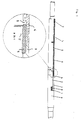
- a heating element 9 according to the invention has a glow tube 3 in which a heating element 1, preferably in the form of a heating coil, if necessary in connection with a control coil, which, embedded in insulating material 8 from the walls of the Glow tube 3 is insulated, is arranged.
- the combustion chamber side The end of the coil 1 is with the tip of the glow tube 3 connected by contact.
- the connection end of the helix 1 is with the inner pole 2, which from the Heating rod is led out, connected.
- the length of the glow tube 3 usually only corresponds about a third to a half of the total length of the Glow plug.
- connection-side end region of the glow tube 3 is insulated from the inner pole lead 5, on its combustion chamber side End range on. In the present case it serves the insulating O-ring 4 in between.
- a contact tube 6 Via the connection-side end region of the glow tube 3 a contact tube 6 is pushed on or pushed into it and in contact with the end region of the glow tube 3 firmly connected, for example by reducing the Contact tube 6 on the glow tube 3.
- the contact tube 6 is to the end of the glow plug body or out of it guided and the end against the pole lead 5, for example by an isolating O-ring 7, isolated at the same time the sealing of the cavity between the contact tube 6 and inner pole lead 5 forms; this cavity is with insulation material 8, for example magnesium oxide in powder form, filled.
- contact tube 6 with glow tube 3 allows the use of different wall thicknesses and different Materials for the named components; so can, for example, a glow tube with a wall thickness of about 1 mm can be used, for example Inconel 601 or 6025 HT is used as the material while the contact tube has a wall thickness of 0.5 mm and from one Material that is not as resistant to high temperatures as the material of the glow tube must be.
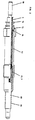
- the extended heating element according to Figure 1 is part of the Glow plug design according to FIG. 2.
- the glow plug body 12 is opposite the heating element arranged in isolation.
- an insulation 11.3, for example made of ceramic, glass or high temperature resistant plastic provided while in connection side area of the body on an insulating Seal 14 and the insulating washer 15, opposite the contact tube isolated, arranged.
- connection side 12 On the end area of the body from the connection side 12 emerging area of the contact tube 6 is a connecting sleeve 16 applied, which serves as a ground connection, and preferably designed for connection to a coaxial connector is.
- the pole lead / inner pole is on the connection side as Plus connection trained.
- an insulation layer 19 applied to the glow plug tip a defined non-insulated To provide an area for ionization measurement.
- the glow plugs according to the invention can be economical mass-produced on the known devices become; assembly is very simple and can be done at the same time very low concentricity tolerances are observed.
- the contact tube 6 placed on the glow tube 3 of the heating element 9 and the Cavity between contact tube 6 and inner pole 2 / pole lead 5 filled with insulating material, for example MgO 8, and with closed with an O-ring.
- insulating material for example MgO 8
- the inventive design of the glow plug becomes electrically and mechanically stable contacting of the connections guaranteed; at the same time it allows minimization the diameter of the heating element and candle body and with it the whole glow plug.
Landscapes
- Engineering & Computer Science (AREA)
- Chemical & Material Sciences (AREA)
- Combustion & Propulsion (AREA)
- Mechanical Engineering (AREA)
- General Engineering & Computer Science (AREA)
- Resistance Heating (AREA)
- Materials For Medical Uses (AREA)
- Organic Low-Molecular-Weight Compounds And Preparation Thereof (AREA)
- Spark Plugs (AREA)
Abstract
Description
Claims (3)
- Stabglühkerze mit einem Glühkerzenkörper und darin angeordnetem Heizstab, in dem ein in Isolierstoff eingebettetes Heiz- und gegebenenfalls diesem zugeordneten Regelelement angeordnet ist, das am anschlußseitigen Ende mit einem Innenpol mit Innenpolzuleiter mit einer Stromquelle verbindbar und dessen brennraumseitige Seite mit der Heizstabspitze verbunden ist, dadurch gekennzeichnet, daß ein Kontaktrohr (6) vorgesehen ist, das auf den anschlußseitigen Endbereich des Heizstabes (9) aufgeschoben ist, so daß der Heizstab (9) in anschlußseitiger Richtung verlängert wird, wobei der Hohlraum zwischen Kontaktrohr (6) und Innenpol (2)/Innenpolzuleiter (5) mit Isoliermaterial (8) verfüllt ist, und wobei der Glühkerzenkörper (12) um Heizstab (9)/Kontaktrohr (6) gegen diese isoliert angeordnet ist.
- Stabglühkerze nach Anspruch 1, dadurch gekennzeichnet, daß sich das Kontaktrohr (6) bis zum anschlußseitigen Ende der Glühkerze erstreckt und zur direkten Kontaktierung, bevorzugt mittels Koaxialsteckers oder Anschlußhülse (16), ausgebildet ist.
- Verfahren zur Herstellung einer Stabglühkerze mit einem Glühkerzenkörper und darin angeordnetem Heizstab, in dem ein in Isolierstoff eingebettetes Heiz- und gegebenenfalls diesem zugeordnetes Regelelement angeordnet ist, das am anschlußseitigen Ende mit einem Innenpol mit Innenpolzuleiter mit einer Stromquelle verbindbar und dessen brennraumseitige Seite mit der Heizstabspitze verbunden ist, dadurch gekennzeichnet, daß man ein Kontaktrohr (6) auf das Glührohr (3) des Heizstabes (9) aufsteckt, den Hohlraum zwischen Kontaktrohr (6) und Innenpol (2)/Polzuleiter (5) mit einem Isolierstoff (8), vorzugsweise MgO, auffüllt, und durch an sich bekannte Reduzierung zu einer unlösbaren Verbindung von Kontaktrohr (6) und Glührohr (3) kaltverfestigt, wobei die Länge des Kontaktrohres (6) derart gewählt ist, daß dessen anschlußseitiges Ende bis in den anschlußseitigen Endbereiches des Glühkerzenkörpers (12) oder aus diesem herausgeführt und als Masseanschluß zur direkten Kontaktierung, bevorzugt mittels Koaxialsteckers, ausgebildet wird.
Applications Claiming Priority (2)
| Application Number | Priority Date | Filing Date | Title |
|---|---|---|---|
| DE10128656 | 2001-06-15 | ||
| DE10128656A DE10128656A1 (de) | 2001-06-15 | 2001-06-15 | Stabglühkerze und Verfahren zu ihrer Herstellung |
Publications (3)
| Publication Number | Publication Date |
|---|---|
| EP1267125A2 true EP1267125A2 (de) | 2002-12-18 |
| EP1267125A3 EP1267125A3 (de) | 2006-07-26 |
| EP1267125B1 EP1267125B1 (de) | 2008-05-21 |
Family
ID=7688132
Family Applications (1)
| Application Number | Title | Priority Date | Filing Date |
|---|---|---|---|
| EP02004894A Expired - Lifetime EP1267125B1 (de) | 2001-06-15 | 2002-03-04 | Stabglühkerze und Verfahren zu ihrer Herstellung |
Country Status (7)
| Country | Link |
|---|---|
| US (1) | US6649875B2 (de) |
| EP (1) | EP1267125B1 (de) |
| JP (1) | JP4204265B2 (de) |
| KR (2) | KR100953678B1 (de) |
| AT (1) | ATE396368T1 (de) |
| DE (2) | DE10128656A1 (de) |
| ES (1) | ES2302768T3 (de) |
Families Citing this family (5)
| Publication number | Priority date | Publication date | Assignee | Title |
|---|---|---|---|---|
| US20050098136A1 (en) * | 2003-11-10 | 2005-05-12 | Visteon Global Technologies, Inc. | Architecture to integrate ionization detection electronics into and near a diesel glow plug |
| ATE544034T1 (de) * | 2004-09-15 | 2012-02-15 | Beru Ag | Druckmessglühkerze für einen dieselmotor |
| KR20100078097A (ko) * | 2008-12-30 | 2010-07-08 | 삼성전자주식회사 | 막의 두께 산출 방법 및 이를 이용한 막 형성 방법 |
| EP2469256B1 (de) * | 2010-12-22 | 2016-09-21 | HIDRIA AET Druzba za proizvodnjo vzignih sistemov in elektronike d.o.o. | Zündkerze mit Lastsensor und gesiebter Sensorverknüpfung |
| US9534575B2 (en) * | 2013-07-31 | 2017-01-03 | Borgwarner Ludwigsburg Gmbh | Method for igniting a fuel/air mixture, ignition system and glow plug |
Family Cites Families (13)
| Publication number | Priority date | Publication date | Assignee | Title |
|---|---|---|---|---|
| US4281451A (en) * | 1978-02-10 | 1981-08-04 | General Motors Corporation | Electric heater -method of making |
| US4425692A (en) * | 1981-03-23 | 1984-01-17 | Jidosha Kiki Co., Ltd. | Glow plug for use in diesel engine and method of manufacturing the same |
| JPS58138923A (ja) * | 1982-02-12 | 1983-08-18 | Ngk Spark Plug Co Ltd | 二線式グロ−プラグ |
| JPH0814374B2 (ja) * | 1986-02-10 | 1996-02-14 | 日本特殊陶業株式会社 | 自己制御型グロープラグの製造方法 |
| JPS6361662U (de) * | 1986-10-09 | 1988-04-23 | ||
| JP3737880B2 (ja) * | 1998-04-15 | 2006-01-25 | 日本特殊陶業株式会社 | グロープラグ |
| US6064039A (en) * | 1998-04-15 | 2000-05-16 | Ngk Spark Plug Co., Ltd. | Glow plug with small-diameter sheath tube enclosing heating and control coils |
| JP3655499B2 (ja) * | 1998-08-11 | 2005-06-02 | 株式会社ボッシュオートモーティブシステム | セラミックヒータ型グロープラグおよびその製造方法 |
| DE19920758C1 (de) * | 1999-05-05 | 2000-12-21 | Beru Ag | Glühkerze und Verfahren zur Herstellung derselben |
| JP2001336468A (ja) * | 2000-03-22 | 2001-12-07 | Ngk Spark Plug Co Ltd | グロープラグ制御装置、グロープラグ、及びエンジンの燃焼室内のイオン検出方法 |
| DE10031893A1 (de) * | 2000-06-30 | 2002-01-10 | Bosch Gmbh Robert | Glühstiftkerze mit Ionenstromsensor sowie Verfahren zum Betreiben einer derartigen Glühstiftkerze |
| EP1253377B2 (de) * | 2001-04-27 | 2013-12-04 | Ngk Spark Plug Co., Ltd | Heizung, Glühkerze und Wassererhitzer |
| JP2002367760A (ja) * | 2001-06-11 | 2002-12-20 | Ngk Spark Plug Co Ltd | ヒータ及びグロープラグ |
-
2001
- 2001-06-15 DE DE10128656A patent/DE10128656A1/de not_active Ceased
-
2002
- 2002-03-04 AT AT02004894T patent/ATE396368T1/de not_active IP Right Cessation
- 2002-03-04 ES ES02004894T patent/ES2302768T3/es not_active Expired - Lifetime
- 2002-03-04 EP EP02004894A patent/EP1267125B1/de not_active Expired - Lifetime
- 2002-03-04 DE DE50212284T patent/DE50212284D1/de not_active Expired - Lifetime
- 2002-05-06 KR KR1020020024736A patent/KR100953678B1/ko not_active Expired - Fee Related
- 2002-05-23 US US10/152,581 patent/US6649875B2/en not_active Expired - Fee Related
- 2002-06-14 JP JP2002174923A patent/JP4204265B2/ja not_active Expired - Fee Related
-
2008
- 2008-06-30 KR KR1020080062845A patent/KR20080069564A/ko not_active Abandoned
Also Published As
| Publication number | Publication date |
|---|---|
| DE50212284D1 (de) | 2008-07-03 |
| JP2003004230A (ja) | 2003-01-08 |
| US6649875B2 (en) | 2003-11-18 |
| KR20080069564A (ko) | 2008-07-28 |
| EP1267125A3 (de) | 2006-07-26 |
| KR100953678B1 (ko) | 2010-04-20 |
| EP1267125B1 (de) | 2008-05-21 |
| ATE396368T1 (de) | 2008-06-15 |
| US20020190050A1 (en) | 2002-12-19 |
| ES2302768T3 (es) | 2008-08-01 |
| JP4204265B2 (ja) | 2009-01-07 |
| DE10128656A1 (de) | 2003-01-02 |
| KR20020096871A (ko) | 2002-12-31 |
Similar Documents
| Publication | Publication Date | Title |
|---|---|---|
| DE102006016566B4 (de) | Zusammengesetzter Leiter, insbesondere für Glühkerzen für Dieselmotoren | |
| EP0648977B2 (de) | Glühkerze | |
| DD202937A5 (de) | Gluehkerze fuer brennkraftmaschinen | |
| DE10029004C2 (de) | Keramikheizungs-Glühkerze | |
| DE102009048643B4 (de) | Glühkerze und Verfahren zum Verbinden eines Stifts aus einer Funktionskeramik mit einer Metallhülse | |
| DE10047498A1 (de) | Zündkerze kompakter Bauart und Herstellungsverfahren | |
| EP1125475B1 (de) | Keramische glühstiftkerze | |
| EP1240462B1 (de) | Glühstiftkerze | |
| DE19920758C1 (de) | Glühkerze und Verfahren zur Herstellung derselben | |
| DE19852785A1 (de) | Keramische Glühstiftkerze | |
| EP1267125B1 (de) | Stabglühkerze und Verfahren zu ihrer Herstellung | |
| EP1286046A2 (de) | Wasservorwärmstutzen | |
| DE10155230C5 (de) | Stiftheizer in einer Glühstiftkerze und Glühstiftkerze | |
| EP3281264B1 (de) | Zündkerze | |
| DE102004016555A1 (de) | Zündkerze | |
| DE102009015536B4 (de) | Keramischer Glühstift und Glühkerze | |
| DE10152886A1 (de) | Keramische Heizvorrichtung | |
| DE102007053807A1 (de) | Keramische Glühstiftkerze mit verringertem Heizerabstand | |
| EP0997687A1 (de) | Rohrförmige Heiz- oder Messvorrichtung | |
| DE10248045B4 (de) | Glühkerze | |
| DE102010013333B4 (de) | Glühkerze | |
| DE10130488B4 (de) | Glühkerze | |
| DE10004424A1 (de) | Zündkerze | |
| EP1650835B1 (de) | Elektrische Steckverbindung | |
| DE102016223404A1 (de) | Zündkerze |
Legal Events
| Date | Code | Title | Description |
|---|---|---|---|
| PUAI | Public reference made under article 153(3) epc to a published international application that has entered the european phase |
Free format text: ORIGINAL CODE: 0009012 |
|
| AK | Designated contracting states |
Kind code of ref document: A2 Designated state(s): AT BE CH CY DE DK ES FI FR GB GR IE IT LI LU MC NL PT SE TR |
|
| AX | Request for extension of the european patent |
Free format text: AL;LT;LV;MK;RO;SI |
|
| PUAL | Search report despatched |
Free format text: ORIGINAL CODE: 0009013 |
|
| AK | Designated contracting states |
Kind code of ref document: A3 Designated state(s): AT BE CH CY DE DK ES FI FR GB GR IE IT LI LU MC NL PT SE TR |
|
| AX | Request for extension of the european patent |
Extension state: AL LT LV MK RO SI |
|
| 17P | Request for examination filed |
Effective date: 20060828 |
|
| 17Q | First examination report despatched |
Effective date: 20061121 |
|
| AKX | Designation fees paid |
Designated state(s): AT DE ES FR IT |
|
| GRAP | Despatch of communication of intention to grant a patent |
Free format text: ORIGINAL CODE: EPIDOSNIGR1 |
|
| GRAS | Grant fee paid |
Free format text: ORIGINAL CODE: EPIDOSNIGR3 |
|
| GRAA | (expected) grant |
Free format text: ORIGINAL CODE: 0009210 |
|
| AK | Designated contracting states |
Kind code of ref document: B1 Designated state(s): AT DE ES FR IT |
|
| REF | Corresponds to: |
Ref document number: 50212284 Country of ref document: DE Date of ref document: 20080703 Kind code of ref document: P |
|
| REG | Reference to a national code |
Ref country code: ES Ref legal event code: FG2A Ref document number: 2302768 Country of ref document: ES Kind code of ref document: T3 |
|
| PLBE | No opposition filed within time limit |
Free format text: ORIGINAL CODE: 0009261 |
|
| STAA | Information on the status of an ep patent application or granted ep patent |
Free format text: STATUS: NO OPPOSITION FILED WITHIN TIME LIMIT |
|
| 26N | No opposition filed |
Effective date: 20090224 |
|
| PGFP | Annual fee paid to national office [announced via postgrant information from national office to epo] |
Ref country code: AT Payment date: 20090319 Year of fee payment: 8 |
|
| PGFP | Annual fee paid to national office [announced via postgrant information from national office to epo] |
Ref country code: ES Payment date: 20090331 Year of fee payment: 8 |
|
| PGFP | Annual fee paid to national office [announced via postgrant information from national office to epo] |
Ref country code: IT Payment date: 20090326 Year of fee payment: 8 |
|
| PGFP | Annual fee paid to national office [announced via postgrant information from national office to epo] |
Ref country code: FR Payment date: 20090320 Year of fee payment: 8 |
|
| PG25 | Lapsed in a contracting state [announced via postgrant information from national office to epo] |
Ref country code: AT Free format text: LAPSE BECAUSE OF NON-PAYMENT OF DUE FEES Effective date: 20100304 |
|
| REG | Reference to a national code |
Ref country code: FR Ref legal event code: ST Effective date: 20101130 |
|
| PG25 | Lapsed in a contracting state [announced via postgrant information from national office to epo] |
Ref country code: FR Free format text: LAPSE BECAUSE OF NON-PAYMENT OF DUE FEES Effective date: 20100331 |
|
| PG25 | Lapsed in a contracting state [announced via postgrant information from national office to epo] |
Ref country code: IT Free format text: LAPSE BECAUSE OF NON-PAYMENT OF DUE FEES Effective date: 20100304 |
|
| REG | Reference to a national code |
Ref country code: ES Ref legal event code: FD2A Effective date: 20110415 |
|
| PG25 | Lapsed in a contracting state [announced via postgrant information from national office to epo] |
Ref country code: ES Free format text: LAPSE BECAUSE OF NON-PAYMENT OF DUE FEES Effective date: 20110404 |
|
| PG25 | Lapsed in a contracting state [announced via postgrant information from national office to epo] |
Ref country code: ES Free format text: LAPSE BECAUSE OF NON-PAYMENT OF DUE FEES Effective date: 20100305 |
|
| PGFP | Annual fee paid to national office [announced via postgrant information from national office to epo] |
Ref country code: DE Payment date: 20120330 Year of fee payment: 11 |
|
| REG | Reference to a national code |
Ref country code: DE Ref legal event code: R082 Ref document number: 50212284 Country of ref document: DE Representative=s name: KOTITSCHKE & HEURUNG PARTNERSCHAFT, DE |
|
| REG | Reference to a national code |
Ref country code: DE Ref legal event code: R119 Ref document number: 50212284 Country of ref document: DE Effective date: 20131001 |
|
| PG25 | Lapsed in a contracting state [announced via postgrant information from national office to epo] |
Ref country code: DE Free format text: LAPSE BECAUSE OF NON-PAYMENT OF DUE FEES Effective date: 20131001 |